

Page 1
SolidRF MobileForce 4G
Cell Phone Booster Manual
If you have any questions or concerns when
installing or operating your cell phone booster,
please email us:
Please provide the invoice of your product in
your email. Or visit www.SolidRF.ca for more
information.
Systems tested and certified against FCC
standard, Equipment Class: Part 20 Wideband
Consumer Booster (CMRS)
Systems tested and certified against IC standard,
Type of Equipment: Amplifier, RSS-131
Manufactured and Warranted by
SolidRF Technology Inc. Canada
www.SolidRF.ca
IC
Product Diagram
Package Contents
Features
Installation – Step By Step
Technical Specification
Troubleshooting
Find Strongest Signal
Self Oscillation
Page 2
INSIDE
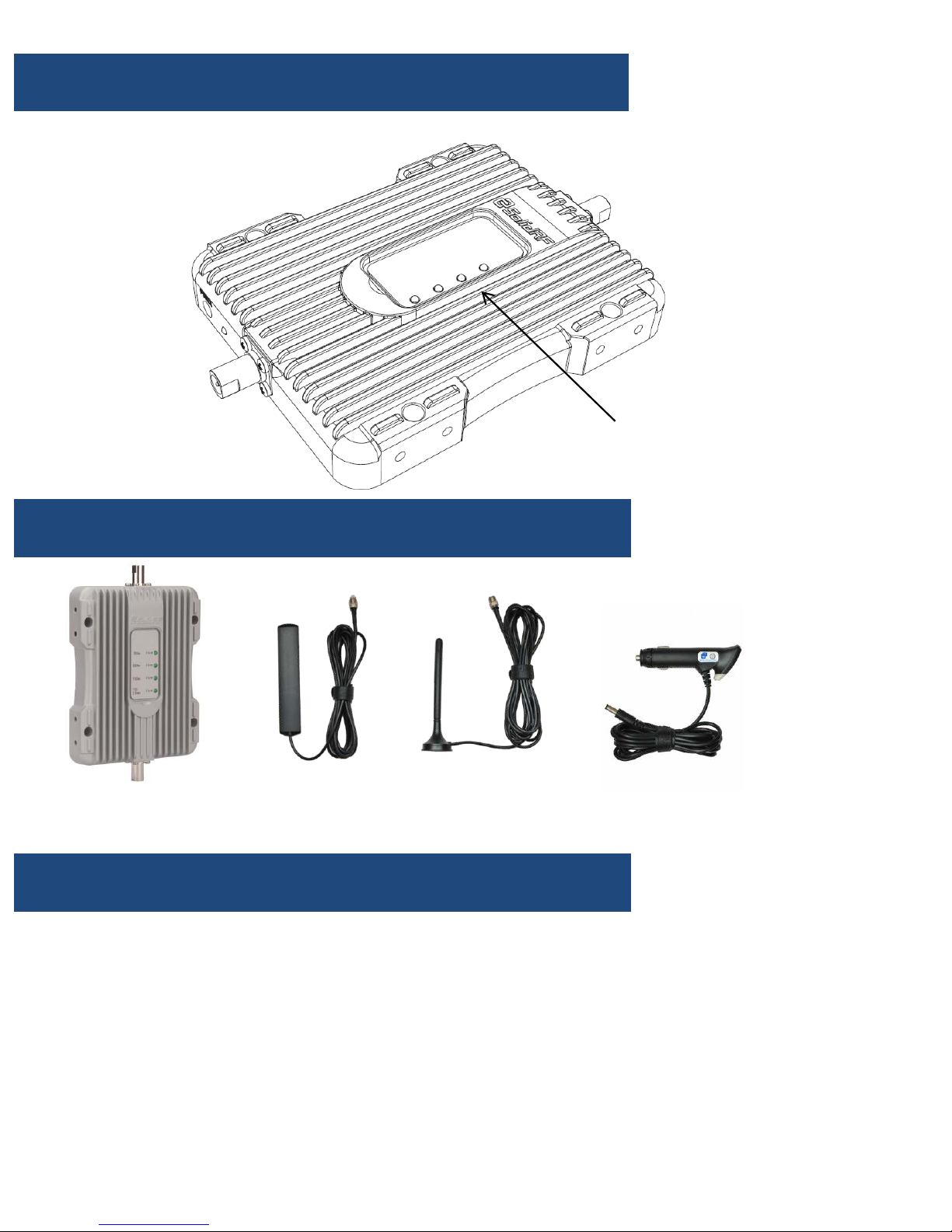
Antenna Connector
Power Light
AC Adapter Port
Product Diagram
OUTSIDE
Antenna Connector
Package Contents
MobileForce 4G
Booster
Features
• Greatly reduces dropped calls, extends signal range, and increases data rates
• Allows multiple mobile devices to be used simultaneously
• Oscillation (or interference) detection and automatic shutdown
• Overload protection circuit – protects cell towers from being overloaded
• Amplifies signal both to and from the cell tower
• Maximum 1 watts(EIRP) output power
• Works on all generations of 2G,3G and 4G
• Power control logic ensures maximum gain is within cellular standards
• Reduces radiation and extends battery life – up to 2 hours additional talk time in weak
signal areas.
Front Panel
Warning Lights
Inside Antenna Outside Antenna Power Adapter
Page 3
STEP BY STEP INSTALLATION
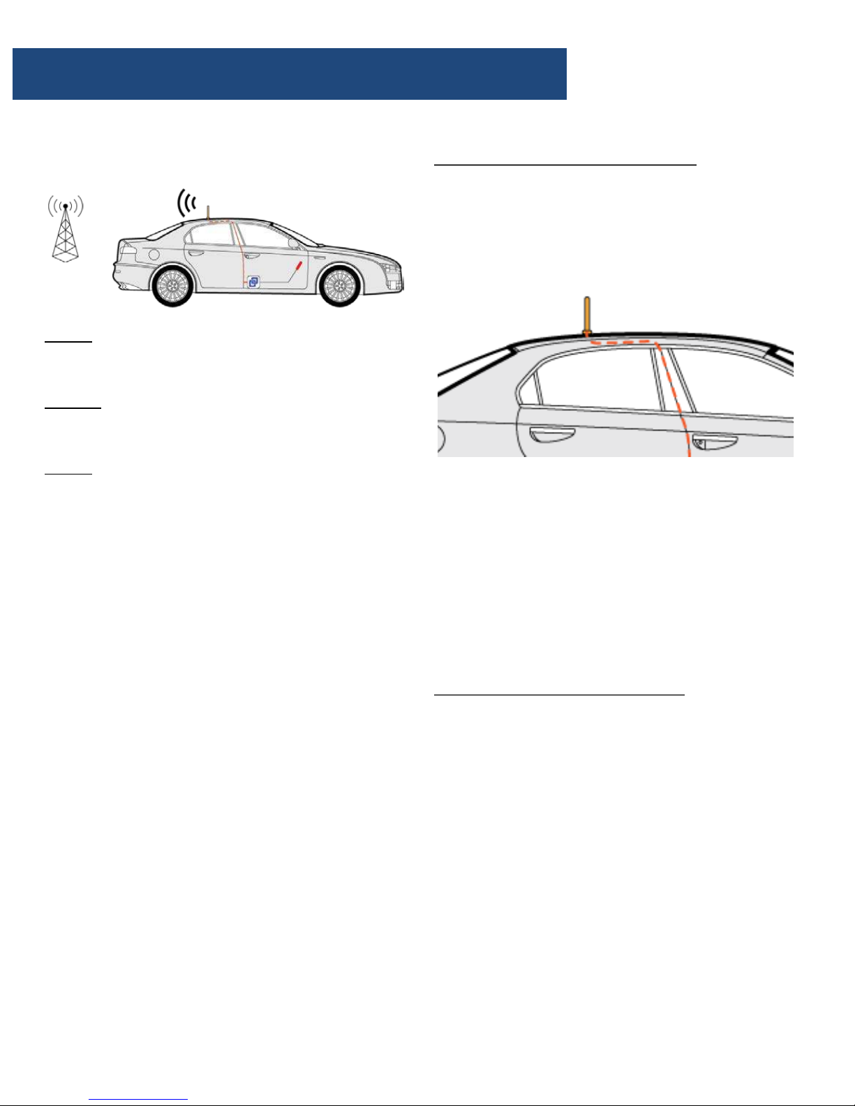
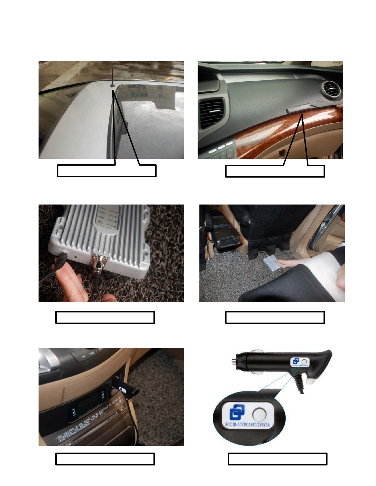
Step 1: Mount the outside antenna
a. Choose right position.
• 30 cm away from any other metallic objects.
• 50 cm away from any windows.
b. Mount the antenna: it must be mounted
vertically on top of the vehicle.
c. Set the outside antenna cable into the
vehicle
• Carefully pull down the door seal, run the
cable into the vehicle under the seal of the
doorframe.
• Run the cable to reach the location where
you plan to place the booster.
• Push the seal carefully back into place.
Step 2: Mount the inside antenna
a. Choose right position
• 20 cm away from any other metallic objects.
• 50 cm away from any windows.
• The inside antenna should be facing to driver
or all passenger’s seats as possible。
Caution: The inside and outside antenna can
NOT directly face each other. This will result in
possible self oscillation. (see self oscillation
section)
b. Mount the inside antenna
• Peel off the plastic on the backside of the
antenna.
• It is the 3M sticker. Place the inside antenna
onto the position selected.
Installation - Step By Step
How does it works
Step 1: The powerful outside antenna captures
a voice and data signal and transfers it to the
booster.
Step 2: The booster receives the signal,
amplifies it and then rebroadcasts the signal by
the inside antenna.
Step 3: Your mobile devices will get a better
signal, never experiencing dropped calls or slow
data speed.
Supported Carriers
• AT&T 2G/3G/4G (HSPA+ & LTE)
• Verizon 3G/4G
• T-Mobile 2G/3G/4G
• Sprint 3G/4G
• US Cellular 3G/4G
• Metro PCS 3G/4G
• Major Canadian Carriers 2G/3G/4G
• All other carriers using 700MHz, 850MHz ,
1900 MHz and 2100 MHz
Conduct a Test Installation
Conduct a test instillation to ensure correct
product functioning before permanently
installing the booster.
The test instillation will help to determine the
best location for the inner and outer antenna
and additionally the routing cable
Page 4
WARNING:
• Do NOT cover the booster body with
anything. This prevents if from cooling
down. If the product becomes overheated,
it will automatically shut off or cause
permanent damage.
• Use only the power supply provided by
SolidRF. Any other non-approved products
by SolidRF of self-made power cables may
damage the booster.
• Connecting the booster directly to the cell
phone with use of an adapter will damage
the cell phone.
• The booster is designed for use in vehicle
O N LY.
• Some of the 12V DC lighter power sources
will not shut down when the vehicle is
turned off. Please ensure to switch off the
adapter when you leave the vehicle to
prevent the vehicle battery from being
drained.
Installation - Step By Step
Step 3: Arrange the booster
a. Choose position
• Under the passenger’s seat, or in the trunk of
the vehicle.
• Free from excessive heat, direct sunlight and
moisture.
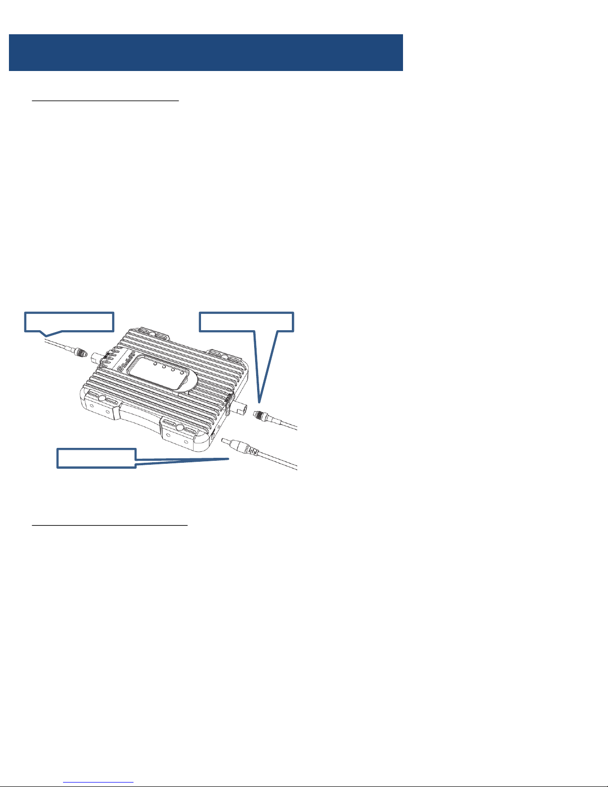
b. Connect the outside antenna’s connector to
the port labeled “OUTSIDE” of the booster.
c. Connect the inside antenna’s connector to
the port labeled “INSIDE” of the booster.
Step 4: Power on the booster
• Plug the power adapter into the power port
on the booster.
• Then plug into the car 12V DC lighter.
• Switch on the adapter by pressing the button
on the power adapter. A blue light will be
seen when it is working.
Inside antenna Outside antenna
Adapter cord
Page 5
Place Outside Antenna
Place Inside Antenna
Connect Cables Place Booster
Plug Power Adapter Switch On
Page 6
Technical Specification
This device complies with Part 15 of FCC rules. Operation is subject to two conditions: (1) This device may not cause
harmful interference, and (2) this device must accept any interference received, including interference that may cause
undesired operation. Changes or modifications not expressly approved by SolidRF could void the authority to operate
this equipment.
RF Exposure: The manufacturer’s rated output power of this equipment is for signal carrier operation. For situations
when multiple carrier signals are present, the rating would have to be reduced by 3.5 dB, especially where the output
is reradiated and can cause interference to adjacent band users. This power reduction is to be by means of input
power or gain reduction and not by an attenuating at the output of the device.
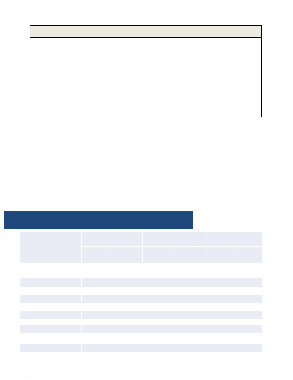
Frequency
(MHz)
LTE
(band 12)
LTE
(band 13)
Cellular
( band5)
PCS
(band 25/2)
AWS
(band 4)
Uplink 698-716 776-787 824-849 1850-1915 1710-1755
Downlink 728-746 746-757 869-894 1930-1995 2110-2155
Gain Uplink 45±2 45±2 45±2 47±2 47±2
Downlink 48±2 48±2 48±2 50±2 50±2
Output power 26±2dBm(Uplink)/-5±2dBm(Downlink)
Noise figure <5dB
In-band Flatness <8dB
Weight 0.7Kg
EIRP 1W
Gain adjustment 20dB
Impedance 50 ohm
Operating temperature -5°~60°
Current ≦1.5A(9V DC)
Dimension(mm) 155*125*25
This is a CONSUMER device.
BEFORE USE, you MUST REGISTER THIS DEVICE with your wireless provider and have your provider’s
consent. Most wireless providers consent to the use of signal boosters. Some providers may not consent
to the use of this device on their network. If you are unsure, contact your provider.
You MUST operate this device with approved antennas and cables as specified by the manufacturer.
Antennas MUST be installed at least 20 cm (8 inches) from any person.
You MUST cease operating this device immediately if requested by the FCC or a licensed wireless service
provider.
WARNING. E911 location information may not be provided or may be inaccurate for calls served by
using this device.
Page 7
ATTENTION: Self Oscillation
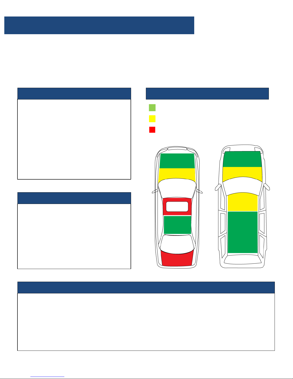
We strongly recommend it should achieve the Recommended Separation Distance for the
installation. The improper installation could result in possible Self Oscillation.
Recommended Separation Distance
: Minimum 1 meter or 1.5 meters (3ft or 5ft ) distance. The
Separation Distance would be variable depends on the vehicle.
When the antennas are too close, they
could pick up each others signals,
creating a feedback loop condition,
which is called Self Oscillation.
By FCC regulations, the cell phone
booster would automatically detect this
condition and immediately shut down to
prevent Self Oscillation from damaging
the cellular network.
What is Self Oscillation:
If the booster detects Self Oscillation, it
will not operate until the condition is
corrected. One way to correct Self
Oscillation is to increase separation
distance between the antennas until the
good separation distance is achieved.
Also the antennas can NOT directly face
each other.
How to correct Self Oscillation:
The Self Oscillation could cause interference to the cellular network, The FCC regulations
extremely prohibit cell phone booster users from causing interference to the cellular networks. If
you were contacted by the FCC or any wireless provider – yours or any other – and told your cell
phone booster is causing interference, you must shut it down until you can fix the interference
problem. Under most situation, it is Self Oscillation problem.
Please refer to:
https://www.fcc.gov/wireless-telecommunications/signal-boosters/faq/signal-boosters-faq.
Why is it so important to prevent Self Oscillation:
Antennas Installation Recommendation
Recommended Area
Possible Area
Not Recommended Area
Page 8

Troubleshooting
Correct functioning:
The lights on the front panel indicate the condition of the booster. Every time the booster is
powered on, all of the lights will be green in color for several seconds then off. This means the
booster has passed the self check and is in good condition.
Incorrect functioning:
• If any of the lights on the front panel are flashing in green, it means that self oscillation is
occurring. You must switch off the booster and check the outside and inside antennas
immediately. Make sure you have followed the recommended installation process and check
each step carefully. Refer to Self Oscillation section for more details of minimum required
separation distance, antennas installation. If you can not fix the problem please contact the
technical support or the reseller.
• If the power light is flashing, please contact the technical support.
SolidRF Technical Support: [email protected]
 Loading...