


Sp. z o.o.
e- mail biuro@solgaz.com.pl
Assembly and operating instructions
OF CERAMIC GAS HOB
for kitchen furniture arrangement
GPC – 3, GPC-3-T

Dear Customer,
Congratulations on your reasonable decision to purchase our
ceramic gas panel to be built in all types of kitchen furniture sets.
Our panel can serve as a part of advanced equipment of a
modern kitchen furniture set. Not only is it highly sophisticated,
but it also looks good and is resistant to extreme temperatures. Its
unquestioned advantages include: low operating costs, easy
operation and environmental-friendly parameters, which you will
be able to evaluate in the course of daily use.
Have fun with preparing your perfect tasty meals.
Yours sincerely,SOLGAZ
The ceramic gas hob must be connected to a gas source by an
authorized person(certified installer)
Dear Sir, Dear Madam,We guarantee that your new gas-fired heating panel will operate
correctly.
However, should you have any problems with using this heating panel, our Company Service
will offer you immediate and professional assistance. We want to guarantee full comfort of in
daily use of our product to all those who have put their trust in our company.
CONTENTS

1. GENERAL INFORMATION
page
1.1. Application of the hob... . . . . . . . . . . . . . . . . . . . . . . . . . . . . . . . . . . . . . . . . . . . . . . . . . . 4
1.2. Technical data of the GPC-3 hob . . . . . . . . . . . . . . . . . . . . . . . . . . . . . . . . . . . . . . . . . . . . 4
1.3. Design of the gas hob . . . . . . . . . . . . . . . . . . . . . . . . . . . . . . . . . . . . . . .. . . . . . . . . . . . . . . 4
2. REQUIREMENTS FOR HOB INSTALLATION
2.1. Requirements for rooms . . . . . . . . . . . . . . . . . . . . . . . . . . . . . . . . . . . . . . . . . . . . . . . . . . . . . 6
2.2. Mounting the hob in kitchen countertop . . . . . . . . . . . . . . . . . . . . . . . . . . . . . . . . . . . . . . 6
2.3. Gas installation. . . . . . . . . . . . . . . . . . . . . . . . . . . . . . . . . . . . . . . . . . . . . . . . . . . . . . . . . . . . . 8
2.4. Electrical installation. . . . . . . . . . . . . . . . . . . . . . . . . . . . . . . . . . . . . . . . . . . . . . . . . . . . . . . 9
3. USING THE HOB. . . . . . . . . . . . . . . . . . . . . . . . . . . . . . . . . . . . . . . . . . . . . 9
3.1. Initial activities, Timer. . . . . . . . . . . . . . . . . . . . . . . . . . . . . . . . . . . . . . . . . . . . . . . . . . . …… 9
3.2. Switching on and setting the heating power of burners. . . . . . . . . . . . . . . . . . . . . . . . . . . . . 9
3.3. Description of operating condition with intelligent reheating function. . . . . . . . . . . . . . . . . 10
3.4. Switching off the burners. . . . . . . . . . . . . . . . . . . . . . . . . . . . . . . . . . . . . . . . . . . . . . . . . . . . 11
3.5. Switching the controller lock on and off. . . . . . . . . . . . . . . . . . . . . . . . . . . . . . . . . . 11
3.6. Residual heat indicator. . . . . . . . . . . . . . . . . . . . . . . . . . . . . . . . . . . . . . . . . 11
3.7. Choice of dishes. . . . . . . . . . . . . . . . . . . . . . .. . . . . . . . . . . . . . . . . . . . . . . . . . . . . . . . . . . 12
3.8. Utilization of combustion gas heat. . . . . . . . . . . . . . . . . . . . . . . . . . . . . . . . . . . . . ….. …. 12
3.9. Reduction of operating time . . . . . . . . . . . . . . . . . . . . . . . . . . . . . . . . . . . . . . . . . . . . . . . . 12
4. HOB CLEANING AND MAINTENANCE . . . . . . . . . . . . . . . . . . . . . . . . . . . . 13
4.1. Cleaning the ceramic plate . . . . . . . . . . . . . . . . . . . . . . . . . . . . . . . . . . . . . . . . . . 12
4.2. Cleaning the hob grids . . . . . . . . . . . . . . . . . . . . . . . . . . . . . . . . . . . . . . . . . . . . . . . 13
4.3. Control and supervision over gas, electrical and ventilation systems . . . . . . . . . . . . . 13
5. INSTRUCTIONS FOR THE INSTALLER . . . . . . . . . . . . . . . . . . . . . . . . . . . . . . . . . . . 14
5.1. General. . . . . . . . . . . . . . . . . . . . . . . . . . . . . . . . . . . . . . . . . . . . . . . . . . . . . 14
5.2. Adapting the cooker for different type of gas . . . . . . . . . . . . . . . . . . . . . . . . . . . . . . 14
5.3. Maintenance and inspection of hob components . . . . . . . . . . . . . . . . . . . . . . . . . . . . . . . 15
6. HANDLING DEFECTS – error signaling . . . . . . . . . . . . . . . . . . . 15
7. CONTROLLER ALARM CONDITIONS SIGNALING. . . . . . . . . . . . . 15
1. GENERAL INFORMATION

1.1. Application of the hob.The GPC-3 type plate is a ceramic hob with 3 gas burners located
Parameters of the hob
Unit
Type of gas
2E
G20
2Lw
G27
2Ls
G2.350
3B/P
G30
Rated pressure
kPa
20
13
37
Gas nozzle of the f 90 (small) burner
mm
0,75
0,82
1,00
0,43
Gas nozzle of the f 120 (medium ) burner
mm
1,00
1,10
1,35
0,60
Gas nozzle of the f 180 (large) burner
mm
1,25
1,37
1,70
0,72
Rated heating power of the appliance
kW
≈5,2
Rated heating power of 90 burner
kW
1,07
1,02
0,94
0,93
Rated heating power of 120 burner
kW
1,81
1,72
1,75
1,60
Rated heating power of 180 burner
kW
2,51
2,50
2,65
2,35
Gas connection
R1/2”
Operating voltage
V
12 V
Power adapter supply voltage
V
230 V/50 Hz
Parameters of the power adapter
12V DC/3,5A
Protection class of the housing
IP- 40
Dimensions (L x W x D)
mm
600x495x110
underneath. This is the newest generation of gas hobs where special gas burners controlled by an
electronic system process heat generated through gas combustion into infrared radiation. Radiation
infiltrating the ceramic plate heats the dishes positioned above the hot fields. Hot fields are
indicated graphically on the plate. This hob is provided with touch sensors for controlling its
operations. It is fit for building in a single kitchen countertop or in a combined countertop. It is
designed for non-professional (home) preparation of food and for household use. Advanced
solutions applied in the hob’s construction and design give it a nice esthetical appearance while
ensuring comfortable and safe use.
1.2. Technical data of the GPC-3 hob
Table 1.
The entire electrical installation of the hob is supplied with a special power pack and is prepared
as a low voltage system.
In terms of fire risk, the hob is classified as a safe device.
1.3. Design of the gas hob. The hob (fig. 1) has three injector gas burners rated as specified in
the table above, with a ceramic insert, equipped with igniting electrodes and ionizing detectors of
burning gas. Burners in which catalytic combustion of gas takes place produce infrared radiation.
They are covered with a ceramic panel with four separate hot fields above the ceramic burners,
indicated graphically on the panel, and two hot fields above combustion gas ducts of gas burners,
which do not consume gas.
Because the hob controls must be supplied with 12 VDC power, the hob is supplied from a 12V
power source via a special power adapter, included with the delivered hob. Nozzles adapted to
commonly used G 20 gas are installed in the delivered hob by default. The gas source can be a gas
network, or a liquid gas cylinder. Through replacing the working nozzles according to Table 1 and
changing the size of air diaphragm according to Table 3, the user is able to adapt the hob to
burning a different type of gas. Nozzles for all applicable types of gas are included in the this
manual. A touch control panel is located in the front part of the hob (fig. 2). It is for controlling
and regulating the specific gas burners of the cooker. It also displays relevant messages of the hob
operating conditions.
10
3
6
5
8 1
7 94
1
2
12V DC
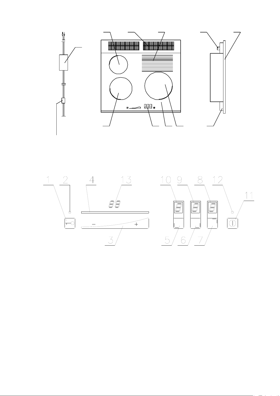
Fig. 1
1 – ceramic plate, 2 – hot field A ø120, 3 – hot field C ø90, 4 – hot field D ø180, 5 hot aera 6 –
combustion gas outlet, 7 – controller,, 8 – gas inlet, 9 – power supply socket 10 – power adapter
Fig. 2 (control panel – item 9. on fig. 1.)
1 user lock, 2 – lock indicator, 3 - – power setting, 4 – power setting indicator 5,6,7 – burner
selection fields 8,9,10 – digital indicator of burner power settings, 11 – on/off switch, 12- on/off
indicator, 13- Timer indicator
2. REQUIREMENTS FOR HOB INSTALLATION
All activities related to hob installation and connection to gas and electrical system
should be performed by a certified installer.
NOTE: Before installing the hob and connecting it to the gas installation, make sure it is
adapted for the right type of gas supply and that this gas corresponds to the gas type given on
the hob’s rating plate. (by default, cookers are adapted to G 20 gas). Otherwise, adapt the
hob through replacing the nozzles and air diaphragms with the types appropriate for the
given type of gas. In case of any doubt as to the type of gas supplied via the network, please

contact your gas supplier. Proceeding in such case is described in details under 5.2 of the
5 4 0 ± 1
m in
. 1 5 0
4 7 0
40
6 0 0
+1
m in .3 8
4 9 5
5 8 1
1 5 0
48
instruction.
2.1. Requirements for rooms. The rooms designated for installing the hob should be dry and airy,
with efficient natural ventilation.
2.2. Installation and assembly in furniture
All activities related to the assembly and connection of the stove to the gas and electric
systems must be performed by an authorized installation technician.
Assembly of the hob in kitchen countertops
Due to the large size of the hob it is not recommended to install it in the countertops of individual
kitchen cabinets. A composite kitchen countertop where the gas hob is to be installed must be
permanently fixed to the cabinets or permanently connected with other elements of the furniture. In
order to place the hob in the kitchen countertop or in a composite countertop, it is necessary to
make an opening in it with the following dimensions, depending on the type of the hob 540x465
mm. If the hob is to be installed over an oven, the opening where the stove is to be installed must
be symmetric.
If the hob is to be placed next to cabinets standing on the countertop or in the corner of the room,
the plate of the gas hob must be placed at least 150 mm away from the side of the cabinet or wall.
The way to install and fix a 3-burner hob is presented in the drawing.

Fig. 3. Installation
500
1
2
140
50
min. 15 mm
min. 15 mm
1
2
3
side view front view
Fig. 4. Assembly
1-VENTILATION AIR INLET
2- VENTILATION AIR INLET WITH GRID
Fig. 5. Hob with oven arrangement
1 – VENTILATION AIR INLET IN THE BOTTOM PART OF THE SHELF; 2 – VENTILATION AIR INLET
WITH MESH; 3 – AIR
REMARKS:
- Due to the height of the hob, it is impossible to install it over an oven in standard kitchen
cabinets.
- If the kitchen cabinet has a back wall, it is absolutely necessary to cut out ventilation openings in
it, as shown on the drawing.fig. 5,

-Because of the need to assure circulation of air, an air inlet grate should be installed in the skirting
of the cabinet fig. 4.
2.3 Gas supply system
-GPC-3 have a vertical connector pipe ending with an R1/2” outside thread (ISO 7-R1/2) for
connecting the hob to the gas supply system. It is recommended that the hob be connected to the
gas supply system with a flexible connecting hose with a safety certificate.
-If the hob is supplied by means of a flexible connecting hose, it is necessary to use an R ½ /G ½
screw-in/screw-on elbow. A cut-off valve must be installed in the system to stop the supply of gas
to the hob, as well as a gas filter preventing the nozzles from clogging due to polluted gas.
-If the hob is to be supplied with liquid gas from a gas cylinder, a ø10/R1/2” connector pipe is to
be screwed into the gas supply connector pipe, after removing the ½” nipple. A liquid gas
regulating valve needs to be installed on the cylinder valve. The regulating valve is connected
with the hob with a flexible hose for liquid gas (max. length 3 m) with clamps on both ends. The
regulating valve and the flexible hose must have safety certificates.
-The above activities, for the sake of the user’s safety, should be performed by an authorized gas
installation technician!
2.4. Electric system
The control system of the hob is supplied with 12 V direct current through a power supply. In
order to assure correct and safe operation of GPC-3 hobs, it is necessary to provide an electric
socket (230 V/50 Hz) close to the location of the stove in order to connect the hob’s power supply.
The electric socket should have a grounding bolt and cannot be located directly over the hob, at the
distance of less than 10 cm away from the side of the stove and at least 10 cm above the top plane
of the hob plate, away from the area affected by hot fumes exhausted in the back of the hob.
Moreover, it is necessary to provide properly ventilated place for the power supply. In other
places, a special cable to connect the hob with a 12 V DC system will provided on request.
3. USE OF THE HOB
3.1 The startup of the hob should be performed by an authorized technician in the buyer’s home.
The hob can be turned on after it is properly installed in the kitchen cabinet countertop, the type of
gas is verified, and it is connected to the gas and electric supply systems. After the hob is
connected to the gas supply system, it is necessary to checki if gas does not leak from the
connection.
If an exhaust hood is installed over the hob, then the minimum distance between the hood and the
ceramic plate of the hob may not be less than 750 mm. Before starting the hob, the ceramic plate
should be washed with soft cloth and soapy water or a cleaning agent. After the plate dries, the
burners can be ignited.
After the startup, due to the combustion of protective lubricants, it is necessary to ventilate the
room by opening the window or turning on the mechanical ventilation. This increases the air
exchange in the kitchen and allows the faulty smells to be removed.
Before the hob is started up and the individual burners are ignited, the following must done:
- put the supply cable plug of the power source into the socket of the power supply system and put
the low-voltage 12 V cable ending with a round plug in the hob supply socket. The socket is
located on the bottom of the hob.
- open the gas cut-off valve.
After the hob is connected to the electric system, it is ready for work, which is indicated by a diode
located next to the sensor.
-after the sensor of the main switch is touched with a finger, its indicator is turned off and the hob
is ready to receive instructions. For 5 seconds, all indicators show “0”. If we take no further steps,

after a while the electronic system of the hob goes into a standby mode, the indicators are switched
off and the main switch sensor is turned on again.
-TIMER function, touch the burner selection fields twice (Fig.2, no 5,6 or 7), touch “+” and “-“
to select time in minutes (from 1 to 99 min.), the burner stops automatically after selected time
3.2. Switching on and setting the heating power of burners.
NOTE!!!! - do not switch on the hob burners for a prolonged period without filled dishes put
on the hot fields first!!! Otherwise, your device might be damaged. When you choose any
single burner by touching the controller activating field no 5, or 6, or 7 on fig. 2 and set the
power by touching the power setting slider, no 2 fig. 2, within a range exceeding “0”, the selected
burner will go on. This is supposed to happen within less than 5 seconds of enabling the
controller via on/off sensor – no 11 on fig. 2. If the delay is longer than specified above, the
burner will not start and the controller will switch to standby mode until further instruction is
received. All changes of controller program status are accompanied by short sound signals. To
start individual burners of the hob, make sure you do the following: Put a filled pot on the relevant
heating pad.
- Touch the on/off sensor no 11 fig. 2. “0” indicators will light up in fields 5, 6, 7. If you touch
the sensor corresponding to the selected burner – fig. 2. again, as needed and as indicated on the
heating panel, you start the second stage of burner setting. Slide your finger along the setting slider
– no 3 on fig. 2 – to set the required power of the heating pad. At that time, the power setting
display – no 4 of fig. 2 – displays a row of diodes and a digital message shows in the previously
selected field, within the range of 0 to 9, showing the power value set. As the row of diodes
extends and the message number displayed increases, the burner power increases as well, and
opposite – if you slide your finger towards the key symbol, you will reduce the power setting. The
row of LEDs will simultaneously become shorter and the numbers displayed are lower, to finally
reach “0”. “9” corresponds to the maximum heating power of the burner, and “0” corresponds to
no power set.
- After 1 to 3 seconds, the burner will start burning gas (the ceramic insert under the heating plate
will turn red when fully heated).
You may also vary the burner power in a different way. First activate the selected burner
(fields 5, 6, 7, of the controller) by touching any location within the power setting control field – no
3 on fig. 3. The activated burner’s power will change in increments, to reach the level
corresponding to the touching point. Set the power level using this method within not more than 5
seconds. After 5 seconds of completing the last change of pad power, the control pad of the
controller will stop receiving further instructions, and a new power value of the selected burner
will be set as specified in the preceding step.
Follow the same procedure with each burner.You may touch the sensors described above at
any time to set the desired heating power of burner, in the range from 1 to 9.After each change
of the selected burner’s power setting, the row of LEDs will light up, then go off after a short
time, with only the modified power setting of the active burner being displayed. When you
have started all burners, their power settings are displayed accordingly and the LED row – no
4. fig. 2 is off. Burners that have not been switched on in the relevant controller field
corresponding to the burner indicated on the panel will remain off and not light up.
If the burner heating power level is set from 1 to 8, the burner will operate in pulse mode,
meaning that when the burner is not burning gas (several to several tens of seconds in one
cycle), it re-circulates heat from incandescent hearth to heating pad of the ceramic panel, thus
achieving better gas intake efficiency.At first (cold) run of burner(s), they heat up during
approx. 1 minute, to switch to pulse operating mode after that time, depending on the heating
power settings.
3.3. Description of operating condition with intelligent reheating function.

The hob operating status with reheating is a transitory condition for rapid achievement
Do not touch the hot field during that time, and do not place heat-sensitive
items on the hot fields, to avoid the risk of burning!
of target temperature of the active hot field, up to the heating power set. It is signaled by the
decimal point lighting up next to the active burner’s digital indicator (5,6,7, fig2).
- If any level of heating power is set for the given hot field, the controller display will show a
number corresponding to the power setting. With this setting, the operating condition with
automatic reheating function will start automatically. This status is additionally signaled by
decimal point on the display corresponding to the given hot field. It takes up to 18 minutes,
depending on the power setting. Then, the hob’s controller switches to automatic heating
cycles.
- You can change the heating power level of the selected sensor while working with automatic
reheating function using the corresponding sensor and following the procedure described above
under. 3.2.
- The automatic reheat operating mode of the given hot field is controlled by an electronic
system.
3.4. Switching off the burners. In order to switch off any of the operating burners, touch the
corresponding sensor, then slide your finger along the slider towards the “key” so that to reduce the
burner’s power setting to “0” (gas supply shutdown). During this operation, the row of LEDs (no
4 fig. 2) showing the power level goes down and the digits decrease from the level previously set to
level “0”. When level “0” is reached and the controller is ready for restarting, the letter “H” will
display after a moment, indicating that the panel is hot in the location of the burner that has just
been shut down. You may also switch off the entire hob. To do so, touch the main shutdown switch
sensor, or press and hold the power setting slider around zero power for some time, having
previously activated the selected sensor for switching down the burner. All working burners will go
off and those just shut down will display the letter “H”.
3.5. Switching the controller lock on and off. The purpose of controller lock is to secure the
hob’s electronic system against accidental startup or changing the power setting of active
burner. To avoid unauthorized activation (e.g. by a child, a drop of water, or an item being placed
on a working controller), switching off or changing heating power settings of burner(s), use the
controller lock as follows:
- touch the sensor /key/ with your finger – no 1 fig. 2 at least twice in 2 seconds’ time. When
pressed shortly twice, the controller will be locked,
- signaling LED lighting up and a sound signal no 2 fig. 2 indicating the controller lock status, a
long sound signal will be heard simultaneously. The hob controller does not respond to any
instructions except for lock status change.
Proceed in a similar way to deactivate the lock status:- touch the sensor with your finger (no 1 fig.
2) twice within up to 2 seconds,
- the signal LED (no 2 fig. 2) goes off, the lock is off, and a sound signal is emitted.
3.6. Residual heat indicator. After a hot field is shut down, it remains hot for a certain time, and
the “H” message is displayed. The above applies to all operating burners being shut down.
When this indicator goes off, you may safely touch the heating pad.
Cautions – in case of a electricity cut, the residual heat indicator will go
off and the pad may still be hot.
Note: ”H” also refers to the additional hot area, which means that additional hot field (no 5 fig.1)
may be hot as well.
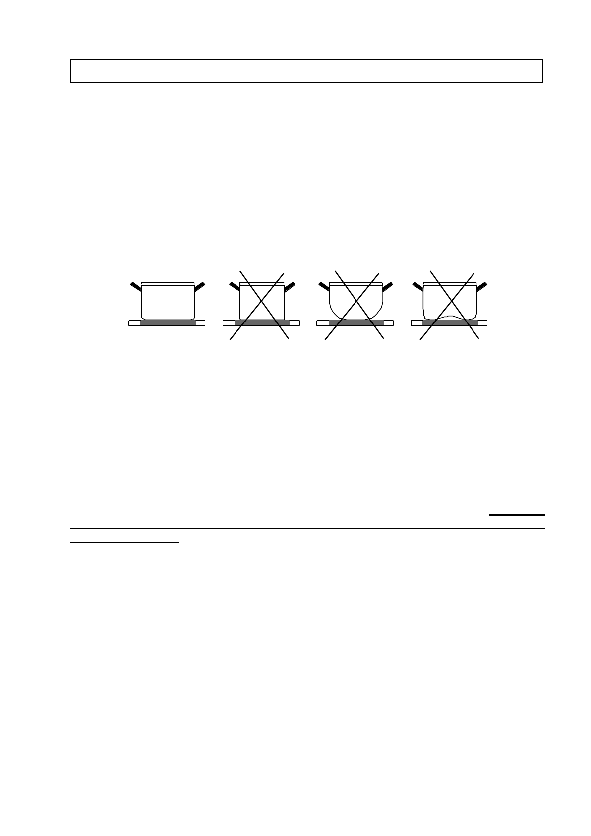
3.7. Choice of pots. To maximize utilization of heat transmitted by infrared radiation emitted by
the gas burner, use appropriate dishes that must have:
- diameter similar to hot field size,
flat bottom of appropriate thickness, min. 4 to 6 mm for stainless steel pots. In addition, the dishes
-
must have lids (if allowed by recipe). Make sure the lid does not protrude outside the dish and
condensate does not drip on the ceramic panel. You will thus avoid difficult stains on the surface of
the panel.
Cooking time is significantly longer for formed-bottom dishes, as the bottom receives only a
part of infrared radiation emitted by the hot field.Place the dishes in the middle of graphically
indicated hot field before switching on. To avoid scratching the surface of the hob’s plate, do not
move any dishes with materials stuck to the bottom, like grains of sand or remnants of cleaning
agents.
NOTES – for obvious reasons, you are not allowed to:
- use plastic dishes!!!
- use aluminum dishes
- put empty dishes on the hob’s heating fields when a burner is working!!!Do not put
dishes on or do not block the combustion gas outlet grate at the back of the hob, particularly
when it is working !!!
3.8. Utilization of combustion gas heat. The GPC-3 ceramic gas plate has additional hot field –
no 5, which is shown on fig. 1, using the heat of combustion gas leaving the burner to the outlet
grate situated in the rear part of hob. This hot area can be used for warming up meals that do not
require high temperature. Use of this hot area significantly reduces the hob maintenance costs, as
we utilize the heat of combustion gas emitted from the burner. Note:
- the additional hot area is hot and you must remember it to avoid getting burnt when touching it.
- do not allow boiling over of prepared dishes and avoid grease splashing on the ceramic plate, as
the food remainders and oil can get burnt.
3.9. Reduction of operating time.
To improve operating safety, the hob has a working time limiter for each hot field. The
maximum operating time setting is determined automatically according to recently selected heating

power setting.If you do not change the heating power level for a long time, then the corresponding
Power setting
0 1 2 3 4 5 6 7 8
9
Maximum heating pad operating
time (hours)
0
10 5 5 4 3 2 2 1 1
hot field is automatically shut down and the residual heat indicator “H” is activated. However, you
can switch
on and use the individual fields at any time, according to operating instructions. These relationships
are given in Table 2.
Table 2.
4.. CLEANING AND MAINTENANCE OF THE HOB
REMARK: All the activities related to the cleaning of the ceramic plate must be performed
after the plate cools down to an ambient temperature.
4.1. Cleaning the ceramic plate
When cleaning the ceramic plate, it is necessary to follow the same rules as those for cleaning glass
surfaces. Do not use abrasive or aggressive cleaning agents, scrubbing sand, or sponges with
scratchy surfaces. Using such materials can cause irreparable scratches on the surface of the
ceramic plate.
4.2. Cleaning after each use
- Slight, not-scorched stains should be wiped off with a damp cloth without a cleaning agent.
Using dishwashing liquid may cause bluish discoloration. These persistent stains cannot always be
used at first try, even using a special cleaning agent.
- Sticky stains should be removed with a sharp scrubber. The surface should then be wiped with a
damp cloth with special protective agent.
Removing stains
Light stains, with a pearly color (aluminum residue) can be removed from a cold ceramic plate
with a special cleaning agent. Calcium residues (caused, e.g. by boiling water) can be removed
with vinegar or a special cleaning agent.
When removing sugar, food leavings containing sugar, plastics, or aluminum sheet, one must not
turn off a given heating field! It is necessary to immediately precisely scrape off the leaving (while
they are hot) with a sharp scraper from a hot heating field. After the stain is removed, one may
turn off the stove and clean the cooled ceramic plate with a special cleaning agent.
A cleaning agent must never be applied on a hot ceramic plate
- Cleaning of the hob grids
1.The fume exhaust grids should be cleaned, the same as the ceramic plate, with a damp cloth and a
little dishwashing liquid, and then wiped dry with a cloth.
2.It is not allowed to use acidic cleaning agents.
3.Cleaning should be performed only after the surface to be cleaned is cooled off, the same as in
the case of the ceramic plate.
4.A fume outlet made from enameled steel should be cleaned with an abrasive sponge, after it cools
off.
4.3 Control and supervision over gas, electrical and ventilation systems. To ensure proper and
safe operation of your hob, please check the condition of the gas, electrical and ventilation systems.
The scope of inspection should cover:

x
1
2
Gas type
Diaphragm distance from pipe edge – X (mm)
Small burner
Medium-sized burner
Large burner
G20; G27
6 9 no diaphragm
G235
5 8 no diaphragm
3B/P
4 7 no diaphragm
- checking the technical condition of the aforementioned systems,
- notifying the building administrator of any doubt concerning the technical condition of these
installations.
5. INSTRUCTIONS FOR THE INSTALLER
5.1. Activities related to hob installation, connection to gas and electrical systems and
adjusting hob burners to a different type of gas can only be carried out by a properly trained
and certified worker.
Upon completion of the aforementioned activities, the installer must acknowledge their
completion (list of activities, date, signature and company seal) in the hob guarantee card, which
is the basis for retaining guarantee and warranty rights for the hob. Otherwise, your guarantee
will be voided.
Before commencing hob installation and connection to the gas and electrical systems, the
installer must make sure that:
- the room in which the hob will be used conforms to the requirements of standards (size,
-
dimensions, location of hob),
- the gas and electrical installations are built in accordance with valid standards and regulations
Note: After installing the hob, the installer must carry out initial startup. During initial startup,
squealing can be heard at combustion gas outlet. This is normal, caused by gas feeding to gas tubes
and burner. It will disappear after first startup.
5.2. Adapting the hob for different type of gas. If the hob needs to be adjusted to a different type
of gas than the standard one replace gas nozzles in all burners with items appropriate for the given
type of gas, according to list of nozzles in the Technical Specifications of these Operating
Instructions (item 1.2) and set the volume of input air with a diaphragm, setting the gap for
dimensions as specified in Table 3. Nozzles can only be replaced by an trained installer.
Table.3

Reason
identification
Condition signal
flame presence signal after
switching on the valve
Alarm G
Letter "G” on controller indicators,
showing in the field corresponding to
the burner without flame.
No flame decay signal after
switching off the gas valves.
Flame decay waiting time is 5
seconds.
Alarm C
Letter "C” on the controller display at
the burner where flame decay was not
observed. The controller is locked and
the gas supply is shut down.
Overheated controller, no
ventilation, or concealed
combustion gas outlet.
Spill over alarm
Alarm D
Alarm E
Letter “D” on controller display. It
remains until the hob cools down to
working temperature.
A liquid spilled over or any two touch
fields were activated at the same time
(for example when cleaning the glass)
5.3. Maintenance and inspection of hob components. If the hob is operated in accordance with
these instructions, cleaned and maintained according to the description presented in sub-clause 4.1,
- then a hob that works properly does not require inspection.
6. HANDLING DEFECTS – error signaling
Please read the following guidelines before calling the manufacturer’s service technician:
- The reheating pad heats up but does not glow during operation of the burner pad.
- Regular bursting noise of spark generator and valve can be heard while starting up the heating
pad before gas is lit. Individual hot field may glow with varying power. These occurrences and
sounds are normal in an operating hob. The burner located under the hot field controls its
temperature through switching on and off. When low heating power setting is chosen for the hot
field, the burner will go off for a longer time, or for a shorter time in case of higher heating power,
accordingly. In case of gas pressure drop in the network or cylinder, the hob will be automatically
locked. This is signaled by the letter “G”.
7. CONTROLLER ALARM CONDITIONS SIGNALING
Alarm messages may display as a result of faults in hob operation, or gas shortage in network.
Identifications of alarm conditions and controller’s signals are given in Table 4.
Table 4.
Additional information:

The following will be delivered together with your hob:
- Power supply adapter.
Our service center’s phone no.: +48 074 856 52 88
serwis@solgaz.com.pl
correspondence address: SOLGAZ Sp. z o. o.
58-124 Marcinowice
ul. Spoldzielcza 3
Poland
-----------------------------------------------------------------------------------------------------TYPE: GPC – 3
SERIAL NUMBER…………………………………….
INSTALLERS SIGNATURE…………………………..
DATE:
 Loading...