

Page 1
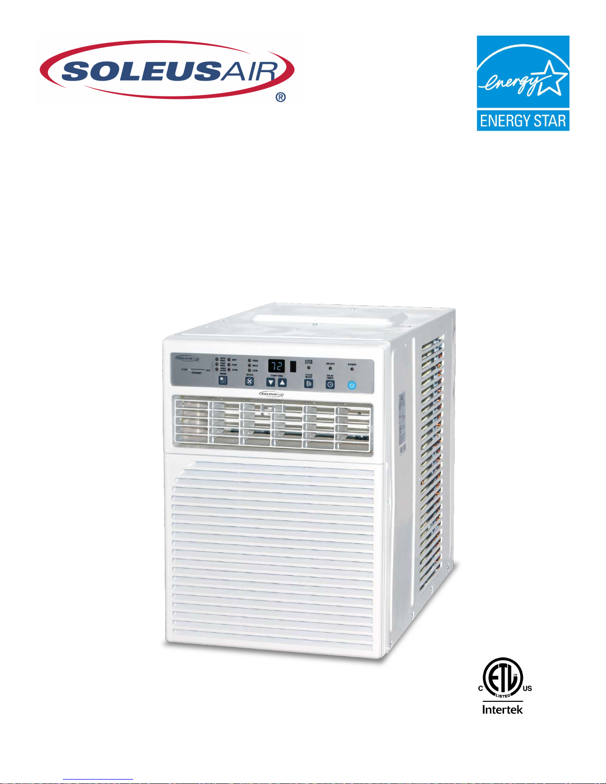
Model
WCM1-08E-01
8,000 BTU
Electronic Casement Window Air Conditioner
Operating Instructions
Page 2
Thank you for choosing a Soleus Air Air Conditioner. This owner’s manual will provide you with
valuable information necessary for the proper care and maintenance of your new product. Please take
a few moments to thoroughly read the instructions and familiarize yourself with all the operational aspects of your new air conditioner.
For your own records, please attach a copy of your sales receipt to this manual. Also, write the store
name/location, date purchased, and serial number below:
Store Name: ____________________________________________________
Location: ______________________________________________________
Date Purchased: _________________________________________________
Serial Number (located on back of unit): ______________________________
IMPORTANT SAFETY INSTRUCTIONS
Before installing and using your air conditioner, please read this owner’s manual carefully. Store this
manual in a safe place for future reference. Your safety and the safety of others is very important to
us. Please pay attention to all safety messages outlined in this owner’s manual.
WARNING: To reduce the risk of fire, electrical shock or injury when using your air conditioner, follow
the following basic precautions:
Plug into a grounded 3 prong outlet.
Do not remove the ground prong.
Do not use a plug adapter.
This is a safety alert symbol.
This symbol alerts you to potential hazards that can harm you or others or even cause
death.
All safety messages will directly follow the safety alert symbol and/or the words
“DANGER” or “WARNING”.
Do not use an extension cord.
Unplug the air conditioner before servicing
Use two or more people to move and install the air
conditioner
Failure to immediately follow these
instructions may cause serious injury
or even death.
All Safety messages alert you of potential hazards, how to reduce the chance of injury,
and what can happen if instructions are not followed correctly.
2
Page 3
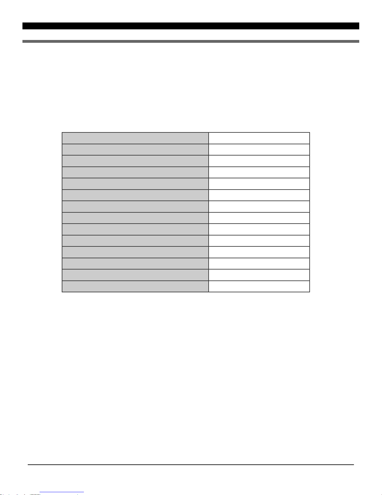
SPECIFICATIONS
Noise level is measured at a distance of 3.28 ft away from the front of the unit in cooling mode.
Power consumption is measured when the fan runs at the highest speed setting.
These specifications are for reference only. For actual data, please refer to the rating label on the back of the
unit.
Power Supply (Ph/V/Hz) 1/115V/60Hz
Dehumidifying Capacity (Pints/Day) 34.8
Rated Cooling Capacity (BTU/hr) 8,000
Cooling Power Input (Watts) 762
Rated Current Cooling (Amperage) 6.5A
EER/C.O.P 10.5 (cooling)
Noise Level dB(A) (High/Low) 53dB(A) / 49 dB(A)
CFM (High/Med/Low) 263/238/206
Power Plug Type NEMA 5-15P
Product Dimensions (W” x H” x D” ) 14.5” x 20.25” x 23.375”
Package Dimensions (W” x H” x D” ) 18.75” x 23.75” x 26.625”
Net/Gross Weight (Lbs) 67.9 lbs. / 80.4 lbs.
Refrigerant R-410A
Model WCM1-08E-01
3
Page 4
IMPORTANT SAFETY INSTRUCTIONS
Read all instructions before using this air conditioner
These instructions describe installation in a typical wood framed window with a wood SLIDE-BY sash, or installation in a
metal CASEMENT window. Modification may be necessary when installing in windows made differently than those
shown in these instructions.
FOR YOUR SAFETY
Do not store or use gasoline or other flammable vapors and liquids in the vicinity of this or any other appliance. Read
product labels for flammability and other warnings.
MEETING ELECTRICAL REQUIREMENTS
OBSERVE ALL LOCAL GOVERNING CODES AND ORDINANCES.
DO NOT, UNDER ANY CIRCUMSTANCES, REMOVE THE POWER SUPPLY CORD GROUNDING PRONG.
NOTE: If codes permit, and a separate grounding wire is used; it is recommended that a qualified electrician determine
that the grounding path is adequate and not interrupted by plastic, non-metallic gaskets, or other insulating materials.
RECEPTACLE WIRING
Receptacle wiring should be a minimum of 14 gauge. Use copper wire only. It is your responsibility to provide proper and
adequate receptacle wiring, installed by an electrician.
ELECTRICAL REQUIRMENTS
A 115 volt (103.5 minimum, 126.5 maximum), 60 Hertz, AC only, 15 ampere fused electrical supply is required. A time
delay fuse or time delay circuit breaker is also required. A separate circuit, serving only this appliance, MUST be provided.
WARNING: Electrical Shock and Personal Injury Hazard
Electrical ground is required on this appliance.
DO NOT ground to a gas line.
If a cold water pipe is interrupted by plastic, non-metallic gaskets, or other insulating materials, DO NOT use for
grounding.
Check with a qualified electrician if you are in doubt as to whether the appliance is properly grounded.
DO NOT modify the power supply cord plug. If it does not fit the outlet, have the correct outlet installed by a qualified
electrician.
DO NOT have a fuse in the neutral or grounding circuit. A fuse in the neutral, or grounding circuit could result in an
electrical shock.
DO NOT use an extension cord with this appliance.
Failure to follow these instructions could result in electrical shock, serious injury or death.
4
Page 5
IMPORTANT SAFETY INSTRUCTIONS (Continued)
Read all instructions before using this air conditioner
ACCIDENT PREVENTION
To reduce the risk of fire, electrical shock, or injury to persons when using your air conditioner, follow basic precautions,
including the following:
Be sure the electrical service is adequate for the model you have chosen. This information can be found on the
rating label located on the side of the cabinet or behind the grille.
If the air conditioner is to be installed in a window, you will probably want to clean both sides of the glass prior to
installation. If the windows is a triple-track type with a screen panel included, remove the screen completely before
installation.
Be sure the air conditioner has been securely and correctly installed according to the installation instructions
provided with this manual. Save this manual and the installation instructions for future use when removing and
reinstalling the unit.
When handling the air conditioner, be careful to avoid cuts form sharp metal fins on the front and rear coils.
NOTE: The power supply cord on this unit contains a current detection device designed to reduce the risk of fire.
Please refer to the page “LCDI POWER CORD AND PLUG” for details. In the event that the power supply cord is
damaged, it cannot be repaired, it must be replaced with a cord from Soleus Home Comfort.
ELECTRICAL INFORMATION
The complete electrical rating of your new air conditioner is stated on the product rating label located on the unit. Refer
to the ratings on the label when checking electrical requirements.
Be sure the air conditioner is properly grounded. To minimize shock and fire hazards, proper grounding is important.
The power cord is equipped with a three-prong grounded plug for protection against shock hazards.
Your air conditioner must be used in a properly grounded wall receptacle. If the wall receptacle you intend to use is
not adequately grounded or protected by a time delay fuse or circuit breaker, a qualified electrician will have to install
the proper receptacle.
Do not run the air conditioner with a protective cover on the outside of the unit. This could result in mechanical dam-
age within the air conditioner.
Do not use an extension cord or an adapter plug.
WARNING:
Avoid fire hazard or electronic shock,
DO NOT use an extension cord or an adapter plug.
DO NOT remove any prong from the power cord.
DO NOT
under any circumstances,
cut, remove, or bypass the
grounding prong!!
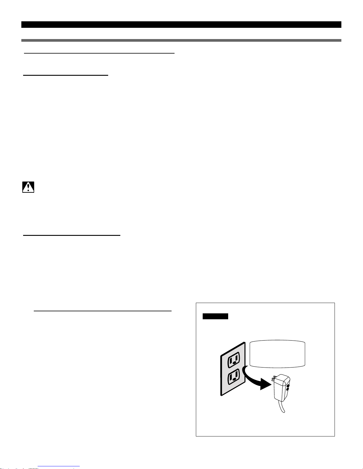
Power supply cord with 3-prong grounding
plug and current detection device
5
Page 6
6
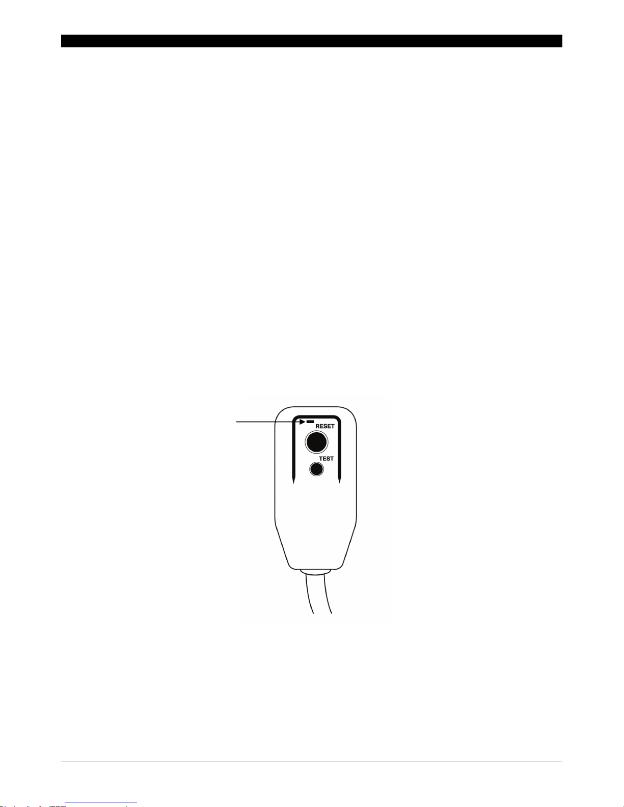
LCDI POWER CORD AND PLUG
This air conditioner is equipped with an LCDI (Leakage Current Detection and Interruption) power cord
and plug as required by US National Electric Code 440.65. This cord consists of a length of shielded flexible cord with no termination on the load side and a LCDI attachment plug on the line side.
The LCDI power cord and plug will remove the supply source via electrical disconnect (circuit trip) if the
nominal current leakage between the cord shield and either load conductor exceeds a predetermined
value. The cord will remain de-energized until the devise has been manually reset. This is intended to reduce the risk of a fire in the power cord or combustible materials nearby. The cord shields are not grounded
and they must be considered a shock hazards if exposed. The cord shield must not be connected to ground
or to any exposed metal.
The test and reset buttons on the LCDI Plug are used to check if the plug is functioning properly. To test:
1. Plug power cord into wall outlet. The LED light will turn on.
2. Press TEST Button, circuit should trip, cutting power to the air conditioner. When this occurs,
3. Press RESET button to restore power to the machine. Once power is restored, the LED light
will turn on again.
If test button is pressed and unit can still be turned on, current leakage has been detected. Do not use the
air conditioner or attempt to reset the LCDI Plug. Contact Soleus Air Customer Service for troubleshooting
recommendations.
WARNING:
1. DO NOT press the TEST button while the air conditioner is operating.
2. The TEST and RESET buttons should not be used as “ON” and “OFF” switches.
3. The cord and plug are not intended to offer protection to externally connected loads or supply circuits.
4. The cord and plug are intended for indoor use only.
LED LIGHT
the LED light will turn off.
Note: Your units power cord and plug may differ from the one shown.
Page 7
PREPARING FOR INSTALLATION
Installation Tips
For wood-frame casement windows: It may be necessary to construct a frame, using at least 1-inch
thick wood, with a 15-1/2-inch wide opening.
For brick or cement building construction: It may be necessary to put a wood stool strip under AC,
for mounting purposes.
Tools Required:
Flat-head screwdriver
Phillips-head screwdriver
Carpenter's level
Tape measure
Fine tooth saw
Electric or hand drill
Knife and scissors
Pencil
WARNING: Failure to adhere to the following precautions could result in personal injury and
product damage.
Because this unit weighs over 80 pounds, it is recommended that you have someone help you when
install your new unit, and that you both use proper lifting techniques.
Inspect the condition of the window where unit will be installed. Be sure it will support the weight of
the unit.
This appliance must be installed according to all applicable codes and ordinances.
Handle AC with care. AVOID sharp metal fins on front and rear coils.
7
Page 8
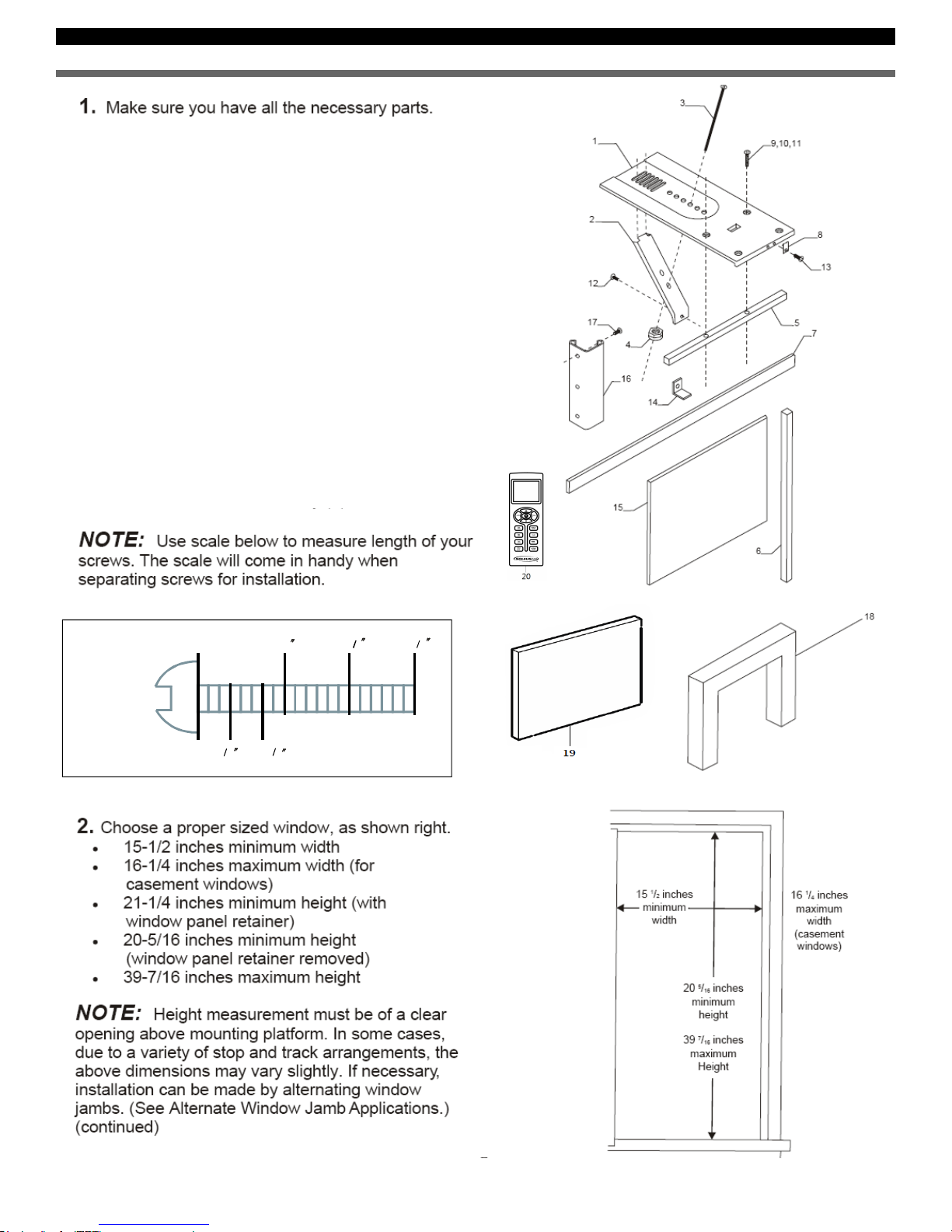
PARTS LIST & INSTALLATION
Installation Kit Contents
1. Platform (1)
2. Support brace (1)
3. Adjustment bolt (1)
4. Hex flange nut—1/4” (1)
5. Track seal (1)
6. Side channel seal (1)
7. Foam seal strip/Sash seal
8. Safety bracket (1)
9-11.Screw—2-1/2” (2), or Screw– 1-
3/4” (2) or Screw– 1” (2)
12. Screw– 3/4” (6)
13. Screw– 3/4” self-threading (7)
14. Window locking bracket (1)
15. Plastic window panel (1)
16. Side channel (2)
17. Screw– 3/8” (6)
18. Panel frame/seal assembly (1)
19. Weather Insulation Board (1)
20. Remote Control (1)
Id entify Screw s
By Leng th
3 8
(1 0m m)
(25mm)
3 4
(1 9m m)
(44mm)
1
1 3 4
(63mm)
2 1 2
8
Page 9

INSTALLATION
INSTALLING THE UNIT IN A SLIDING WINDOW
1. Attach support brace to platform as shown.
Use adjustment bolt and hex flange nut to complete
assembly. Choose slot and adjustment bolt hole
locations that will create a 45 degree angle between
platform and support brace. Try assembly in the
window to determine if platform will rest properly, and
allow proper slope (3/16-inch lower on outside).
NOTE: If you are planning to use a siding protection
board (see Step 5) on the outside of your
house, hold board in place when testing assembly in
window.
2. Measure, and lightly mark a line 8-11/16 inches
from window jamb.
NOTE: If any sash stop protrudes more than 1
inch from the side window jambs, the 8-11/16-inch
measurement must be increased accordingly.
Screen and storm window frames may also require
adjustments to the measurement.
3. Center platform assembly on the line with inside
platform tab pressed against inside edge of window
track. Using the holes in the platform as a guide,
mark and drill two 9/64-inch diameter holes. Drill
holes in either track or stool.
Property Damage Hazard—Failure to adhere
to the following precautions could result in
damage to window or the air conditioner. Make
sure the wood stool or window track is securely
attached to the building construction. Use
longer screws in sub-framing if necessary.
CAUTION
9
Page 10

INSTALLATION—SLIDING
INSTALLING THE UNIT IN A SLIDING WINDOW (CONT.)
4. Peel off protective backing from track seal. Apply
seal to room side of window track. Center of seal strip
should coincide with the line marked in Step 2. The
two screw holes drilled in Step 3 should be directly
above seal strip in the inner track.
5. Securely attach a siding-protection board to
side of house.
NOTE: Siding-protection board should be long
enough to span 2 wall studs.
6. Place platform assembly, with platform tab
against inside of window track, and attach it to
window jamb. Use appropriate length screws (Items
9-11 in Preparing For Installation).
7. Adjust platform assembly so that outside edge is
3/16-inch lower than inside edge, as shown right.
This ensures proper water drainage from the air
conditioner.
8. Level platform assembly from side-to-side.
Also, make sure window track is level. Use leveling
shims as necessary to ensure unit is level from side-to-
side.
9. Measure height of window opening from top of
platform assembly as shown right. Subtract 20-5/8
inches. Mark this measurement on plastic window
panel, along the longer side. (continued)
10
Page 11

INSTALLATION—SLIDING
INSTALLING THE UNIT IN A SLIDING WINDOW
(CONT.)
10. Clamp plastic window panel between a board
and a work table, and cut along cutting line with a fine
tooth saw. Remove any burrs with a file.
11. Fasten side channels to the sides of the AC
using 3 screws (Item 17) per channel. Start with first
screw at top of channel. Make sure hook ends of
channels face toward back of unit.
12. Slide plastic window panel into panel frame,
with the smooth side to the room. Slide panel frame
assembly into side channels of the AC cabinet. Make
sure plastic window panel is firmly enclosed on all
sides by the retainer grooves.
12.1. Weather Insulation Board Installation
NOTE: The Weather Installation Board adds an extra layer of insula-
tion to keep air from passing through the sides of the window air
conditioner.
1. After installing the Plastic Window Panel into Panel Frame, use a
sharp blade or scissors, slowly cut the Weather Insulation Board
to a size that will fit Plastic Window Panel and completely cover
it.
2. Once properly sized, remove the backing to expose the adhesive
tape.
3. Place the Weather Insulation Board over the Plastic Window
Panel and firmly press and hold for 5 seconds (FIG 12.1).
11
Page 12

INSTALLATION—SLIDING
INSTALLING THE UNIT IN A SLIDING WINDOW (CONT.)
13. Cut side channel seal into 2 equal lengths.
Remove protective backing and apply it to the rear
side of cabinet side channels, starting just below
panel frame assembly. Pinch off excess length so
seal is even with the bottom of the cabinet side
channel.
14. To remove front
1. Remove the two front retaining screws from the
front frame.
2. Press firmly on each side of the metal case close
to the front, approximately 2/3 of the way down.
3. While pressing on the sides of the metal case,
gently pull the front out and lift up to release it
from the case.
4. Then remove the four screws from the front frame
to release the control panel box.
NOTE: DO NOT push or pull air direction louvers.
15. Place AC in window opening. As shown right, it
should sit on platform assembly so that window
panel frame, and cabinet side channels are against
top and side window jambs. (continued)
12
Page 13

INSTALLATION—SLIDING
INSTALLING THE UNIT IN A SLIDING WINDOW (CONT.)
16. Slide inner window sash firmly against side
of the cabinet. Make sure not to peel the seal strips
from the window track and cabinet side channels. If
the panel frame does not fit snugly to the inner
window sash, secure the panel frame to the sash
with #8x3/4-inch screws, or #8-32x3/4-inch self-
threading screws. Use the partially plugged holes in
the panel frame. Drill 1/8-inch pilot holes for the
screws.
17. Hook the safety bracket over the base of the
unit and fasten it to the front of the platform
assembly. Use a #8-32x3/4-inch self-threading
screw.
NOTE: The bracket prevents movement of the
air conditioner (either in or out) after completing the
installation.
18. Stuff the foam seal strip/sash seal between
the vertical sash and the window glass, as shown
right.
19. Use the window locking bracket to lock the
inner window sash to the base of the outer window
sash. Use one #8x3/4-inch screw, or #8-32x3/4-
inch self-threading screw. (Drill 1/8-inch pilot hole).
20. To replace the front
First reconnect the coupler plugs, make the exhaust
control positioned through the front in the proper
location. Gently push the front into position on the
cabinet. It should click into place. Then replace the
retaining screws that holds the panel in place.
Do not push or pull the front panel louvers.
Alternate Window Jamb Applications
To install in windows having no flanges or wood stops
on the top and side jambs, the channels and panel
frame must fit against a mating flange (or 1/16-inch
max. thick angle) attached to the window jambs.
Figure A shows this angle installed. Figures B & C
show alternate treatments. On the sash side of the
opening, the leading corner of the inner sash
becomes the flange. You can purchase the angle
Strip locally.
13
Page 14

INSTALLATION—CASEMENT
INSTALLING THE UNIT IN A CASEMENT WINDOW
NOTE: Open the window the maximum amount to allow for clearance of the cabinet. The crank handle
should be removed to allow the platform to be fastened to the jamb. If the window cannot open far enough
(more than 15-1/2 inches) for the cabinet to clear the window, remove the window entirely by drilling out the
rivets. Bolts can serve as the pivots in the future.
To avoid crank handle and window clearance problems, the unit can be installed in a stationary sash section.
However, the horizontal mullion and the 2 glass panels must be removed before installation.
1. Attach support brace to platform as shown. Use
the adjustment bolt and hex flange nut to complete
the assembly. Choose the slot and adjustment bolt
hole locations that will create a 45 degree angle
between the platform and the support brace. Try the
assembly in the window to determine if the platform
will rest properly, and allow the proper slope (3/16-
inch lower on outside).
NOTE: If you are planning to use a siding protec-
tion board (see Step 6) on the outside of your
house, hold the board in place when testing the
assembly in the window.
2. Drill a 9/64-inch diameter pilot hole in the
window jamb an equal distance from each side of the
jamb, and 3/16-inch up from the window sill. If the
hole coincides with the window lever slot in the jamb
bottom, an additional hole will have to be drilled
through the platform edge and the window jamb to
miss this slot.
3. Peel off the protective backing from the track
seal, and stick the seal to the window sill on the
outside of the bottom jamb.
4. Screw the platform assembly to the window
jamb through the pilot hole you drilled in Step 2. Use
a #8x3/4-inch self-threading screw.
14
Page 15

INSTALLATION—CASEMENT
INSTALLING THE UNIT IN A CASEMENT WINDOW (CONT.)
5. Adjust the platform assembly so that the rear of
the air conditioner will be 3/16-inch lower than the
front. This ensures proper water drainage from the
air conditioner.
NOTE: A projection below the base of the air
conditioner will require the rear of the platform to be
7/16-inch lower than the front to create the 3/16-inch
slant from front to rear.
6. Securely attach a siding-protection board to the
side of the house where the platform assembly hit
the house. The siding-protection board should be
long enough to span 2 wall studs.
7. Measure the height of the window opening
from the top of the platform assembly. Subtract
20-5/8 inches. Mark this measurement on the
plastic window panel, along the longer side.
8. Clamp the plastic window panel between a
board and a work table, and cut along the cutting
line with a fine tooth saw. Remove any burrs with
a file.
9. Fasten the side channels to the sides of the
unit using three screws (Item 17) per channel.
Make sure hook ends of channels face toward the
back of unit.
10. Slide the plastic window panel into the panel
frame with the smooth side to the outside. Slide
the panel frame assembly into the side channels
of the air conditioner cabinet. Make sure the
plastic window panel is firmly enclosed on all sides
by the retainer grooves.
10.1. Weather Insulation Board Installation
NOTE: The Weather Installation Board adds an extra layer of in-
sulation to keep air from passing through the sides of the
window air conditioner.
1. After installing the Plastic Window Panel into Panel
Frame, use a sharp blade or scissors, slowly cut the
Weather Insulation Board to a size that will fit Plastic
Window Panel and completely cover it.
2. Once properly sized, remove the backing to expose the
adhesive tape.
3. Place the Weather Insulation Board over the Plastic Window Panel and firmly press and hold for 5 seconds (FIG
10.1).
15
Page 16

INSTALLATION—CASEMENT
INSTALLING THE UNIT IN A CASEMENT WINDOW (CONT.)
11. Cut side channel seal into 2 equal lengths.
Remove the protective backing and apply it to
the rear side of the cabinet side channels,
starting just below the panel frame assembly.
Pinch off excess length so the seal is even with
the bottom of the cabinet side channel.
12. To Remove the Front Panel
1. Remove the two front retaining screws from
the front frame.
2. Press firmly on each side of the metal case
close to the front, approximately 2/3 of the way
down.
3. While pressing on the sides of the metal
case, gently pull the front out and lift up to release it from the case.
4. Then remove the four screws from the front
frame to release the control panel box.
NOTE: DO NOT push or pull the air direction
louvers.
13. Place the air conditioner in the window
opening as shown to the right. It should sit
on the platform assembly so that the window
panel frame, and the cabinet side channels are
against the top and side window jambs. Side
channels should overlap side window jambs
equally.
14. Drill two 9/64-inch diameter pilot holes in
the top window jamb in line with the partially
plugged holes in the panel frame. Secure the
panel fame to the window jamb with two #832x3/4-inch self-threading screws. If additional
holding is necessary, two screws may be used
on the sides of the panel frame as well.
15. Drill two screw-clearance holes in the cabi-
net side channels (near bottom) and two 9/64inch diameter pilot holes in the side window
jambs. Secure the cabinet side channels to the
window jambs with two #8-32x3/4-inch selfthreading screws. When doing this, be careful
not to twist the side channel seals with the
screws.
NOTE: Inserting screws will prevent the air
conditioner from being pushed into the room.
16. To replace the front
First reconnect the coupler plugs, make the
exhaust control positioned through the front
in the proper location.
Gently push the front into position on the cabinet. It
should click into place. Then replace the retaining screws
that holds the panel in place.
16
Page 17

OPERATING YOUR AIR CONDITIONER
Before you start using your air conditioner, please familiarize yourself with the control panel and
remote control functions. This air conditioner can be controlled by the control panel (touch pad)
CONTROL PANEL
10
1) Power On and Off - Press the POWER to turn the unit ON and OFF.
2) Digital Display - Displays the set temperature in Auto, Cool, Dry modes, and current room tempera-
ture in Fan mode. It also displays the set time for the Timer function.
3) Temperature Select - Select the desired temperature by pressing either ▲ or ▼ button when using
the unit in Auto, Cool, Sleep, and Energy Saver modes. The temperature indicator flashes to display
the desired temperature setting. After the temperature is set, the unit will display this temperature setting until it is changed by the user.
4) Delay Timer - Press DELAY TIMER button and select the desired ON/OFF time by pressing either
▲ or ▼ button.
5) Fan Speed Control - Press the SPEED button to cycle through the different fan speeds: High, Me-
dium, and Low.
6) Mode Selection - Press the MODE button repeatedly to cycle between the different modes: Auto,
Sleep, Energy Saver, Cool, Fan, and Dry.
-Auto Mode : Press Mode button repeatedly to cycle to Auto mode. The unit will automatically run
between Cool and Fan based on current room temperature.
-Sleep Mode : Press the SLEEP button to enter the Sleep mode, the fan will run on low to keep fan
noise at a minimum. The temperature setting will gradually increase 2°F above the original set temperature for each of first 2 hours. The unit will keep operating the same temperature until the sleep
mode is turned off.
-Energy Saver Mode : When the unit is in Energy Saver mode, the Energy Saver light will turn on.
Selecting Energy Saver mode will cycle the fan off and on with the compressor to limit energy consumption. Use this feature when the room is unoccupied and a greater range of room temperature is
acceptable.
-Cool Mode : When the unit is in Cool mode, the Cool light will turn on. Use TEMPERATURE SE-
LECT buttons to adjust the desired temperature between 61°F-90°F.
17
Page 18

OPERATING YOUR AIR CONDITIONER
-Fan Mode : When the unit is in Fan Mode, the Fan Mode light will turn on. Fan Mode operates the
unit just like a fan and circulates air throughout the room without any additional cooling.
-Dry Mode : When the unit is in Dry mode, the Dry mode light will turn on. Dry mode operates the
unit as an evaporative dehumidifier to remove excess moisture from the room. Use this feature when
there is excess humidity in the air.
7) Auto-on Delay Timer - To program the Auto-on timer, press the DELAY TIMER button when the
unit is powered off. Press the ▲ or ▼ buttons to set the desired time (1-24 hours) for the unit to
automatically turn on. Auto-off Delay Timer - To program the Auto-off Timer , press the DELAY
TIMER button when the unit is powered on. Press the ▲ or ▼ buttons to set the desired timer (1-24
hours) for the unit to automatically turn off.
8) Check Filter - After the unit is on for 250 hours, the CHECK FILTER light will turn on to remind you
to clean the filter. Press the FILTER RESET button once the filter has been cleaned to turn the light
off.
9) Signal Receiver- Point the remote control to the air conditioner when sending instruction to the unit.
10) Exhaust Control - The Exhaust control allows the air conditioner to re-circulate inside air when it is
set to CLOSED. When it is set to OPEN the air conditioner exhaust air outside and brings in fresh
air. Use the CLOSED position when maximum cooling is needed. OPEN removes stale inside air
and replaces it with fresh air.
18
Page 19

REMOTE CONTROL OPERATING INSTRUCTIONS
Using the Remote Control
LCD Display
MODE
FAN
HIGH
FAN
MED
FAN
LOW
CHILD
LOCK
SLEEP
ENERGY
SAVER
TIMER
C/ F
MYTEMP
MODE
Battery Size: AAA - NOTE: Do not mix old and new batteries or different types of AAA batteries.
19
Page 20

20
1. ON/OFF - Press the button to turn the A/C on or off. When the unit is turned off, the Timer function
will be cancelled. The set temperature will be saved.
2. MODE SELECTION - Press the MODE button repeatedly to cycle between the different modes: Auto,
Cool, Dry (Dehumidifier), and Fan.
3. TEMPERATURE SETTING - Press the ▼ button to decrease the temperature when the unit is on.
Stop pressing the button when the desired temperature is displayed. Temperature range is 61⁰F-90⁰F.
Press the ▲ button to increase the temperature when the unit is on. Stop pressing the button when
the desired temperature is displayed. Temperature range is 61⁰F-90⁰F.
4. FAN - Press the FAN button to turn on the fan mode.
FAN HIGH –Press this button to set the fan speed to high. Can be used in COOL or FAN mode.
FAN MED –Press this button to set the fan speed to medium. Can be used in COOL or FAN mode.
FAN LOW –Press this button to set the fan speed to low. Can be used in COOL or FAN mode.
5. SLEEP MODE - Sleep mode can be activated under Cool mode, Dry mode, Auto mode, and Fan
mode. Press the SLEEP button on the remote control, When in SLEEP mode, the fan will run on low to
keep fan noise at a minimum. The temperature setting will gradually increase to 2°F above the original
set temperature for each of first 2 hours. The unit will keep operating the same temperature until the
sleep mode is turned off.
6. ENERGY SAVER - Press the ENERGY SAVER button to turn on Energy Saver mode. When the unit
is in Energy Saver mode, the energy saver light will turn on. Selecting Energy Saver mode will cycle
the fan off and on with the compressor to limit energy consumption. Use this feature when the room is
unoccupied and a greater range of room temperature is acceptable.
7. TIMER - Press the TIMER button when the unit is off to set up the Auto-on timer. The hour indicator on
the digital display will start flashing. Press the ▲ or ▼ button to set timer within 1-24 hours.
Press the TIMER button when the unit is on to set up the Auto-off timer. The hour indicator on the digi-
tal display will start flashing. Press the ▲ or ▼ button to set timer within 1-24 hours. To cancel the
timer, press the TIMER button repeatedly until the timer mode is off.
8. °C /°F - Press the °C /°F button to switch the temperature between Celsius and Fahrenheit.
9. MYTEMP MODE - Press the MYTEMP MODE button to change the thermostat sensor from the air
conditioner to the remote location. When Mytemp mode is activated, current set temperature will flash
3 seconds on digital display. The air conditioner will cool the area depending on the location and set
temperature of the remote control. Take the remote control with you so the air conditioner cools the
room to your location.
10. CHILD LOCK - Press this button to lock/unlock the remote control buttons.
REMOTE CONTROL OPERATING INSTRUCTIONS
Page 21

OPERATING YOUR AIR CONDITIONER
AIR CONDITIONER FEATURES
There is a 3 minute delay when cooling mode is engaged or disengaged. This delay prevents the compressor from overheating and possible tripping of the circuit breaker. The fan will continue to run during
this time.
4-WAY DIRECTIONAL LOUVERS
Direct air up, down, left, or right throughout the room with the 4-way directional louvers.
Error Code
Error Code Description Solution
E2 Room temperature sensor failure Unplug and re-plug the power cord
E3 Room temperature pipe sensor failure Unplug and re-plug the power cord
If the Error Codes continue to display after unplugging and re-plugging the power cord, contact our customer service at 1-888-8-SOLEUS for further solution.
21
Page 22

TAKING CARE OF YOUR AIR CONDITIONER
CARE AND CLEANING
Clean your air conditioner to keep it looking new
and to minimize dust build up.
Air Filter Cleaning
The air filter should be checked at least once every
month to see if it needs cleaning. Trapped particles
and dust can build up in the filter and may decrease airflow as well as cause the cooling coils to
accumulate frost. To clean the air filter:
1. Open the front grille by pulling downward on the
tab at the top upper corners of the front grille
until the grille is in a 45° position, remove the
filter. (See FIG. 13)
2. Wash the filter using liquid dish soap and warm
water. Rinse the filter thoroughly. Gently shake
the filter to remove excess water.
3. Let the filter dry completely before placing it into
the air conditioner.
4. If you do not wish to wash the filter, you may
vacuum the filter to remove the dust and other
particles.
Wear and Tear
To minimize wear and tear on the air conditioner,
always wait at least 3 minutes before changing
modes. This will help prevent the compressor from
overheating and the circuit breaker from tripping.
Winter Storage
To store the air conditioner when it is not in use for
an extended period of time, remove it carefully from
the window according to the installation instructions
and cover it with plastic or place it in the original
box.
FIG. 13
Cabinet Cleaning
To clean the air conditioner cabinet:
Unplug the air conditioner to prevent shock or a
fire hazard. The cabinet and front panel of the
air conditioner may be dusted with an oil-free
cloth or washed with a cloth dampened in a solution of warm water and mild liquid soap. Rinse
thoroughly with a damp cloth and wipe dry.
Never use harsh cleaners, wax or polish on the
cabinet front.
Be sure to wring excess water from the cloth
before wiping around the controls. Excess water in or around the controls may cause damage
to the air conditioner.
Energy Saving Ideas
Do not block the air flow inside with blinds, cur-
tains or furniture; or outside with shrubs, enclosures, or other buildings.
The capacity of the room air conditioner must fit
the room size for efficient and satisfactory operation.
Install the room air conditioner on the shady
side of your home. A window that faces North is
best because it receives the least amount of
sun exposure.
Close the fireplace damper, floor and wall regis-
ters so cool air does not escape.
Keep blinds and drapes closed for cooling and
open for heating.
Clean the air filter as recommended in the
“Care and Cleaning” section.
Proper insulation and weather stripping in your
home will help limit cool air loss.
External house shading with trees, plants, or
awnings helps reduce the air conditioner’s work
load.
Operate heat producing appliances during the
coolest part of the day. Such as a dishwasher,
oven, or computer.
22
Page 23

TROUBLESHOOTING
PROBLEM
The Air Conditioner will not start
POSSIBLE CAUSES
The air conditioner is unplugged
The fuse is blown/circuit breaker is
tripped.
Power Failure
The current interrupter device is
tripped.
SOLUTIONS
Make sure the air conditioner plug
is pushed completely into the outlet.
Check the house fuse/circuit
breaker box and replace the fuse
or reset the breaker.
The unit will automatically re-start
when power is restored.
There is a protective time delay
(approx. 3 minutes) to prevent
tripping of the compressor
overload. For this reason, the unit
may not start normal cooling for 3
minutes after it is turned back on.
Press the RESET button located
on the power cord plug.
If the RESET button will not stay
engaged, discontinue use of the
air conditioner and contact a
qualified service technician.
The Air Conditioner does not cool
as it should
The Air Conditioner is freezing up Ice blocks the air flow and stops the air
The Remote Control is not working
Airflow is restricted
The temperature control may not be
set correctly.
The air filter is dirty
The room may be too warm
Cold air is escaping
The Cooling Coils are frozen
conditioner from cooling the room
The batteries are inserted incorrectly
The batteries may be dead
Make sure there are no curtains,
blinds, or furniture blocking the
front of the air conditioner
Lower the set thermostat tempera-
ture
Clean the filter. See the Cleaning
and Care Section of the manual.
Please allow time for the room to
cool down after turning on the air
conditioner.
Check for open furnace registers
and cold air returns
See “Air Conditioner Freezing Up”
below.
Set the MODE dial to HIGH FAN
or HIGH COOL and set the thermostat to a higher temperature
Check the position of the batteries.
Replace the batteries
23
Page 24

TROUBLESHOOTING (Continued)
PROBLEM
Water is dripping outside
Water is dripping inside the room
Water collects in the base pan
POSSIBLE CAUSES
Hot and Humid weather.
The air conditioner is not correctly
tilted outside.
Moisture removed from the air is
draining into the base pan.
SOLUTIONS
This is normal
For proper water drainage, make
sure the air conditioner is slightly
tilted downward from the front of
the unit to the rear.
This is normal for a short period in
areas with low humidity and normal for a longer period in areas
with high humidity.
24
Page 25

Warranty
Soleus Home Comfort warrants the accompanying Soleus Air Air Conditioner to be free of defects in material and workmanship for the applications specified in its operation instruction for the period of parts specified
below.
This warranty shall not apply to broken or marred cabinets, accessories, knobs, filters or routine maintenance.
This warranty does not apply to uncrating, setup, installation, removal of the product for repair or reinstallation
of the product after repair.
This warranty does not apply to repairs or replacements necessitated by any cause beyond the control of Soleus
Home Comfort including, but not limited to, any malfunction, defect or failure caused by or resulting from
unauthorized service or parts, improper maintenance, operation contrary to furnished instructions, shipping or
transit accidents, modification or repair by the user, abuse, misuse, neglect, accident, incorrect power line
voltage, fire, flood or other Acts of God, or normal wear and tear.
Warranty service must be performed by a qualified HVAC contractor. Soleus Home Comfort maintains a
centralized service network to provide parts and assist in resolving service problems if difficulties are
encountered. Soleus Home Comfort agress to provide service information, sell repair parts and reimburse the
dealer / serviceman for parts in accordance with Soleus Home Comfort’s Policies and Procedures.
SOLEUS HOME COMFORT MAINTAINS THAT ALL WARRANTIES, INCLUDING IMPLIED WARRANTY OR MERCHANTABILITY ARE LIMITED TO THE TERMS AND CONDITIONS SPECIFIED
ABOVE. SOLEUS HOME COMFORT DISCLAIMS ANY LIBILITY FOR CONSEQUENTIAL OR INCI-
DENTAL DAMAGES AND IN NO EVENT SHALL SOLEUS HOME COMFORT’S LIABILITY EXCEED THE RETAIL VALUE OF THE AIR CONDITIONER.
This warranty covers only new products purchased from our authorized dealers or retailers. It does not cover
internet sales, used, salvaged, or refurbished products.
5 YEARS FOR COMPRESSOR
2 YEAR FOR OTHER COMPONENTS
FOR TECHNICAL SUPPORT AND WARRANTY SERVICE
Please Call (888) 876-5387
Or Write To:
Soleus Home Comfort
17911 East Ajax Circle
City of Industry, CA 91748 USA
www.soleushomecomfort.com
25
 Loading...