

Page 1
V180320
4010450
Air conditioner must be upright for 24 hours prior to operating.
This ensures that the compressor will function as intended.
Page 2

Thank you for choosing a Soleus Air Portable Air Conditioner. This Owner’s Manual will provide
you with valuable information necessary for the proper care and maintenance of your new product.
Please take a few moments to thoroughly read the instructions and familiarize yourself with all the
operational aspects of your new Soleus Air Portable Air Conditioner.
For your own records, please attach a copy of your sales receipt to this manual. Also, write the
store name/location, date purchased, and serial number below:
Store Name: ____________________________________________________
Location: _____________________________________________________
Date Purchased: _________________________________________________
Serial Number (located on back of unit): ______________________________
Before installing and using your portable air conditioner, please read this owner’s manual carefully. Store this
manual in a safe place for future reference.
1) Always place the unit on a level surface.
2) Never use or store gasoline or other flammable vapor or liquid near this unit unless instructed by this manual.
3) Maintain at least 20 inches (50 cm) clearance space around this unit. Do not block or cover air inlet or outlet
grilles.
4) The unit must be connected to a correctly grounded power supply.
5) Do not start or stop the unit by inserting or pulling out the power plug.
6) Do not use an adapter plug or extension cord.
7) Do not use the unit in the immediate surroundings of a bath, a shower or a swimming pool.
8) Do not insert anything into the air outlet. Do not obstruct air inlet or outlet grills unless instructed by this
manual.
9) Do not let children play near this unit.
10) Always inspect the cord for signs of damage before use. If the power cord is damaged, it must be replaced by
the manufacturer or a qualified service technician.
11) When cleaning the unit, always turn the unit off and unplug the power cord.
12) Do not mix old and new batteries in the remote control.
Do not mix Alkaline, Standard (Carbon - Zinc) or Rechargeable (Nickel - Cadmium) Batteries.
IMPORTANT INSTRUCTIONS
PURCHASE INFORMATION
Page 3
Portable Air Conditioner (1)
Exhaust Hose (2)
Exhaust Hose Adapter (2)
Window Kit Panel (3)
Window Kit Adapter (2)
Wing Nut (2)
Secure Screw (2)
Remote Control (1)
AAA Battery (2)
Owner’s Manual (1)
PACKAGE CONTENTS
SPECIFICATIONS
• The cooling capacity is measured at an ambient temperature of DB 95˚F, WB 83 ˚F.
• Noise level is measured at a distance of 3.28 ft away from the front of the unit, when the unit
is in cooling mode.
• Power consumption is measured when the fan runs at the highest speed setting.
• These specifications are for reference only. For actual data, please refer to the rating label on
the back of the unit.
• If the environment temperature is higher than the max operating temperature or lower than the mini-
mum operating temperature, the air conditioner may not work properly.
Model Number LX-140 NT
Capacity Cool/Heat 14,000 BTU/11,500 BTU
Dehumidification 126 pts/Day
Cooling Power Usage 1350 Watts / 11.9 Amps
Heating Power Usage 1150 Watts / 10.2 Amps
Air Flow (H/M/L) 235/197/165 CFM
Power Source 115 V / 60 HZ
Noise Level dB(A) 49-54
Product Weight 71.2 lbs.
Operating Temperature
62℉-86℉
Product Dimension (W x H x D)
16-7/8” W ×15’’D×29-1/4’’ H
Refrigerant R-410A
Page 4
This air conditioner is equipped with an LCDI (Leakage Current Detection and Interruption) power cord
and plug as required by US National Electric Code 440.65. This cord consists of a length of shielded flexible cord with no termination on the load side and a LCDI attachment plug on the line side.
The LCDI power cord and plug will remove the supply source via electrical disconnect (circuit trip) if the
nominal current leakage between the cord shield and either load conductor exceeds a predetermined value.
The cord will remain de-energized until the devise has been manually reset. This is intended to reduce the
risk of a fire in the power cord or combustible materials nearby. The cord shields are not grounded and they
must be considered a shock hazards if exposed. The cord shield must not be connected to ground or to any
exposed metal.
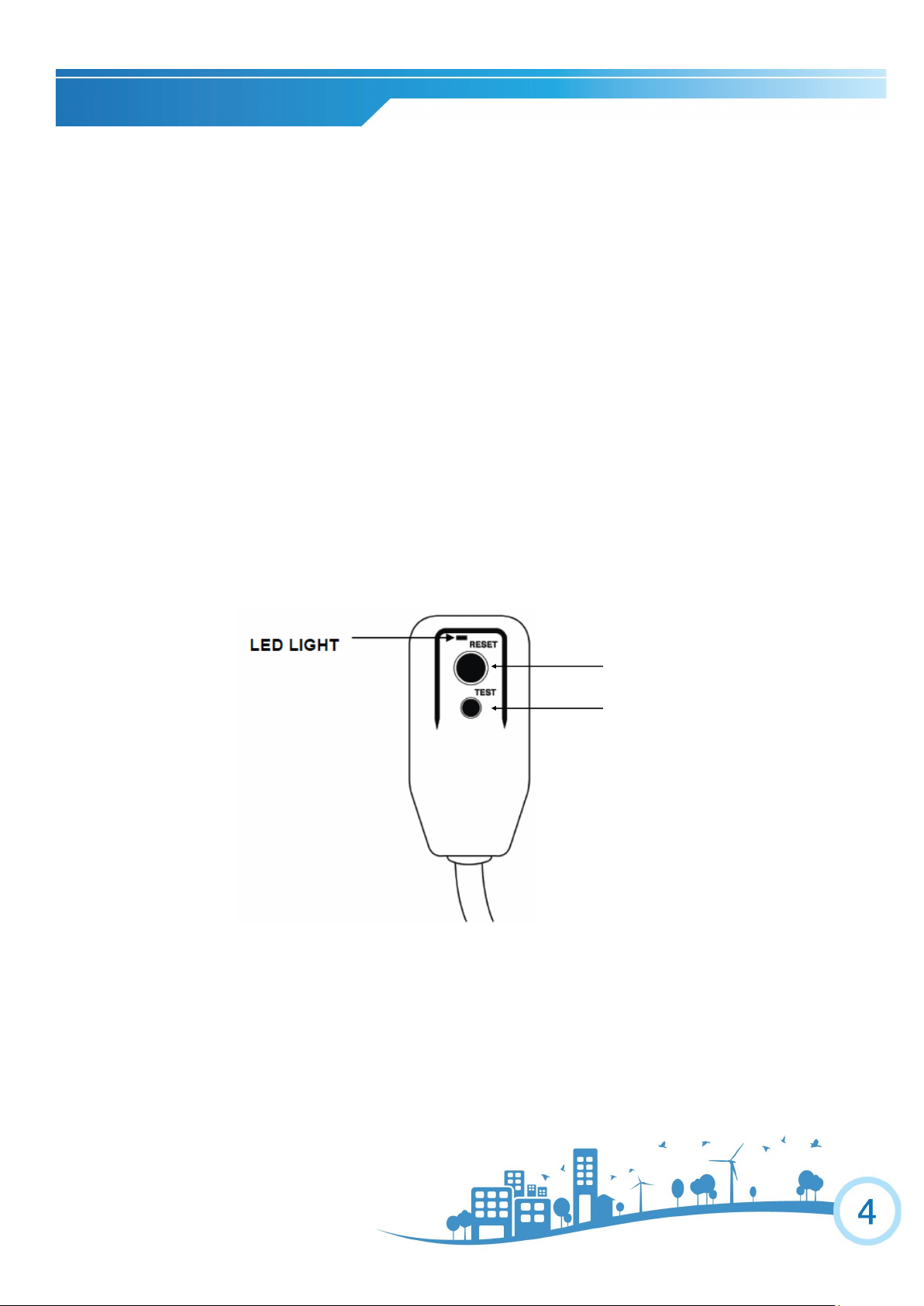
The test and reset buttons on the LCDI Plug are used to check if the plug is functioning properly. To test:
1. Plug power cord into wall outlet, the LED light will turn on.
2. Press TEST Button, circuit should trip, cutting power to the air conditioner. When this occurs,
the LED light will turn off.
3. Press RESET button to restore power to the unit. Once power is restored, the LED light will turn
on again.
If test button is pressed and unit can still be turned on, current leakage has been detected. Do not use the air
conditioner or attempt to reset the LCDI Plug. Contact Customer Service for troubleshooting recommendations.
Note: Your unit’s power cord may
differ from the one shown.
WARNING:
1. DO NOT press the TEST button while the air conditioner is operating.
2. The TEST and RESET buttons should not be used as “ON” and “OFF” switches.
3. The cord and plug are not intended to offer protection to externally connected loads or supply circuits.
4. The cord and plug are intended for indoor use only.
RESET
TEST
POWER CORD AND PLUG
Page 5
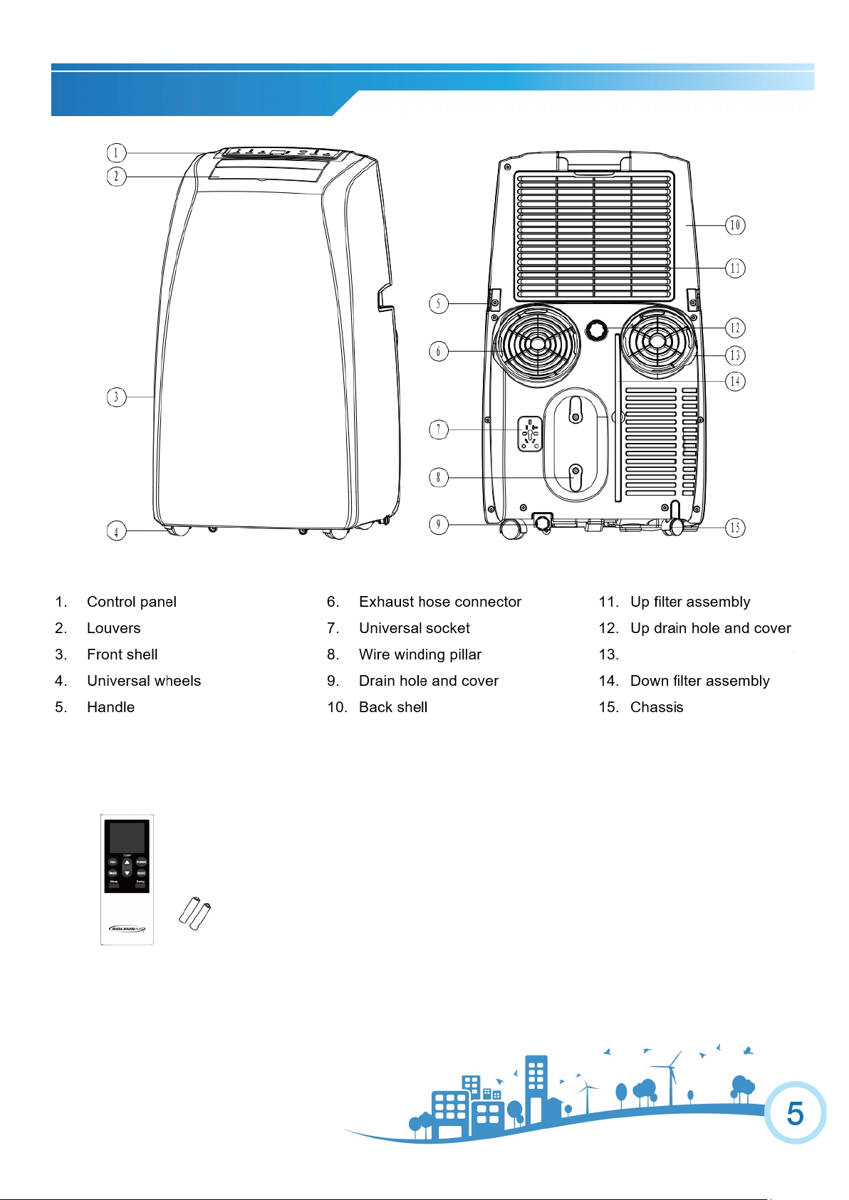
PRODUCT DIAGRAM
16. Remote Control & Battery
Intake hose connector
Page 6
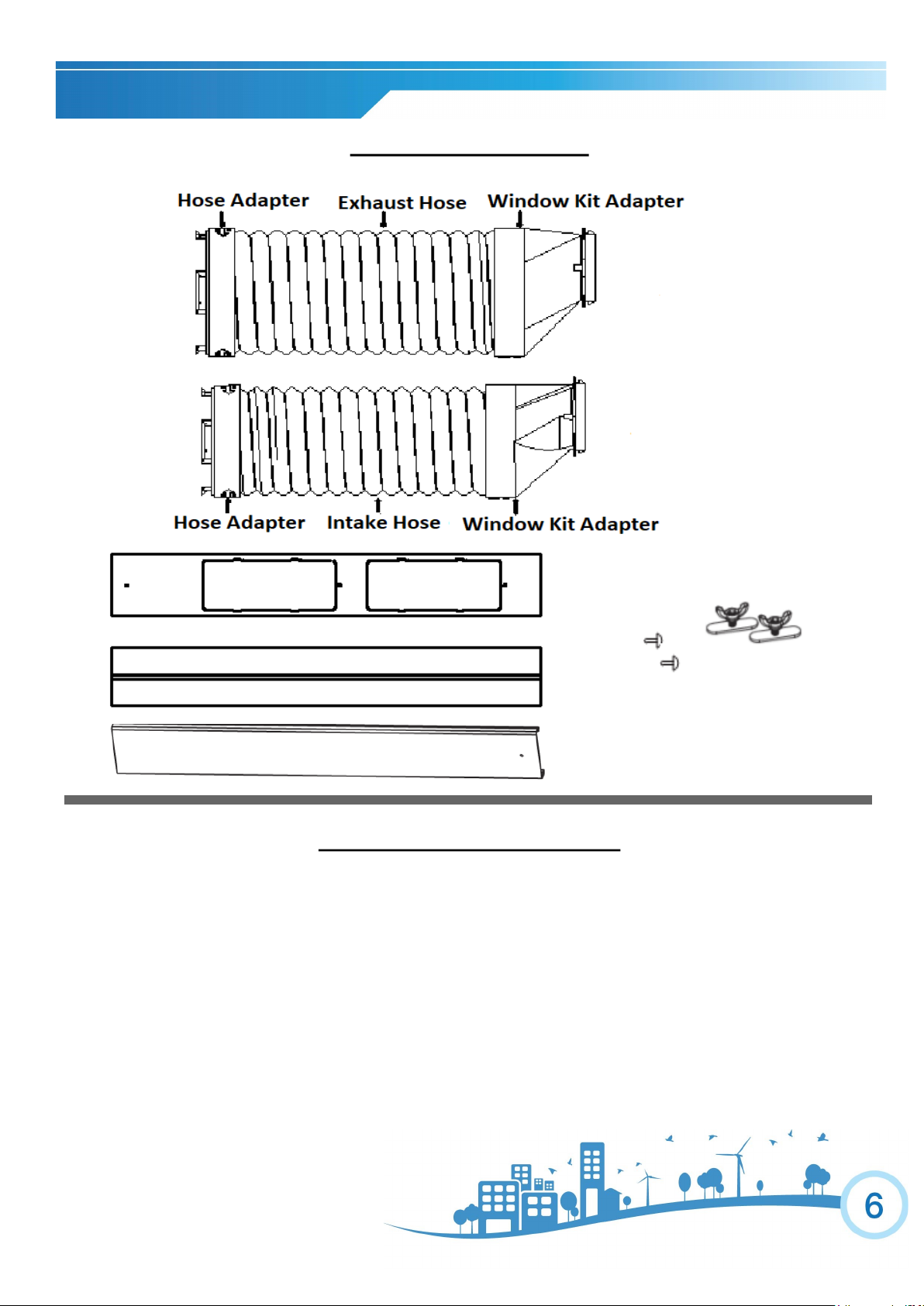
WINDOW VENTING KIT
ASSEMBLY & INSTALLATION
When the unit is operating in air conditioning mode, the unit draws in indoor air and exhausts hot air out of the room
to complete the air exchange. The Window Kit must be installed when operating the unit in air conditioning, dehumidification and heating modes. When the unit is operating in Fan Mode, no outdoor air exchange takes place. The
window kit and exhaust hoses do not need to be installed when the unit is used as a fan.
The supplied window kit can be installed in sliding windows and sliding glass doors up to 7 ft. long
(approximate length). When installed, be sure to keep the exhaust hoses and short and straight as possible for
maximum efficiency.
PARTS & ASSEMBLY
*The two hoses' size are different
Page 7

WINDOW KIT ASSEMBLY
2 Tighten the Wing Nuts after adjusting the length of the
panel according to the height of the window.
1. Using Panel B to connect Panel A & C by placing the Wing
Nut Base on Panel A & C.
3. Connect the exhaust hoses to the window kit.
Secure with the provided screws.
Page 8

.
PORTABLE AIR CONDITIONER
The window venting kit must be installed in order for the unit to work correctly. The window venting kit has been designed to fit into most vertical and horizontal window openings and sliding glass doors up to 7 feet. *The window kit
included with your purchase may vary slightly from what is shown below.
2. Twist the Exhaust Hose Connector
onto Exhaust Hose.
1. Open the window or door to adjust the length of the Window
Kit Panels to fit the opening. If necessary, mark the kit and cut
one end down to properly fit the opening.
3. Twist the Exhaust Hose Connector over the discharge
opening on the back of the unit and extend the Exhaust
Hose. (Keep the exhaust hoses as short and straight as
possible)
4. Attach the Exhaust Hose to the Window Kit
Adapter. Close the window or door tightly.
Make sure the straight side of the window kit
adapters face the wall.
WINDOW KIT INSTALLATION
Keep the exhaust hose as short and straight as possible
for maximum efficiency.
Page 9

OPERATING INSTRUCTIONS FOR CONTROL PANEL BUTTONS
1) Power On and Off - Press the POWER button once to manually turn the unit on. Press the POWER
button once more to turn the unit off.
2) Mode Selection - Press the MODE Button repeatedly to cycle between the different modes: Heat
mode, Air Conditioner (Cool) mode, Dehumidifier (Dehum) mode, Fan-only mode. Each press of the
MODE button will light up a different indicator on the control panel. The exhaust hose and window kit
must be installed when the unit is in Air Conditioner, Heater and Dehumidifier mode. When using the
unit as a fan, the window kit is not required.
3) Temperature - Select the desired temperature by pressing either the ▲ or ▼ button when using the
unit in Air Conditioner or Heat mode. The temperature indicator flashes to display the desired temperature setting. After the temperature is set, the unit will display this temperature setting until it is changed
by the user. The temperature indicator display shows temperature in Fahrenheit. While the unit is
plugged in, press and hold the ▲ and ▼ buttons to switch between Celsius and Fahrenheit.
4) Fan Speed - Press FAN button to choose fan speed in High, Medium or low. Fan speed cannot be
adjusted in Dehum Mode.
5) Timer - Press TIMER button to set the unit automatically turn ON or OFF. Use the ▲ and ▼ buttons
to program the hour increment.
6) Bucket Full - When the unit cannot evaporate the collected moisture fast enough, the excess water
will collect in a backup water tank located inside the unit. The BUCKET FULL indicator will light up.
7) Swing - Press the TIMER and FAN buttons at same time to active the auto swing function.
Fan Speed
Indicators
Air Conditioner
Mode Indicator
Fan Mode
Indicator
Power
Indicator
Bucket Full
Indicator
Timer
Indicator
Dehumidifier
Mode
Heat Mode
Indicator
CONTROL PANEL
Swing Function Sleep Mode
Indicator
Page 10

LCD DISPLAY
POWER BUTTON
TIMER/TEMP DECREASE
TIMER/TEMP INCREASE
SLEEP MODE BUTTON
TIMER BUTTON
SWING BUTTON
MODE BUTTON
FAN SPEED
REMOTE CONTROL
Page 11

1) Power On and Off - When the unit is plugged in, press the POWER button to turn on the unit. Press
the POWER button once more to turn the unit off. When in Air Conditioner mode and Heat mode the
selected temperature will appear on the remote control LCD display. When the unit is in Fan mode or
Dehumidifier mode, no temperature will be displayed. This shows that temperature selection is not
available when the unit is in Fan mode and Dehumidifier mode.
2) Mode Selection - Press the MODE Button repeatedly to cycle between the different modes: Air Conditioner, Dehumidifier, Heat, and Fan-Only mode. The mode icon on LCD display will light up showing
which mode is selected.
3) Fan Speed - Press the FAN button to choose desired fan speed. When the unit is in Dehumidifier
mode, the fan speed cannot be changed.
4) Temperature Setting - When the unit is in Air Conditioner mode or Heat mode, you can select your
desired temperature. Press the ▲ or ▼ to select your desired temperature setting. The temperature
on the LCD display on the remote control will increase or decrease accordingly.
5) SLEEP MODE - When in air conditioning mode, press the SLEEP Button on the remote control, sleep
mode icon will show on the remote control LCD display and the indicator on control panel will illuminate. When in SLEEP mode, the fan will run on low to keep fan noise at a minimum. The temperature
setting will gradually increase 1°F above the original set temperature every 2 hours, up to 4 hours; the
increment will stop until the sleep mode is turned off.
6) TIMER -
Auto-On: Press the TIMER button when the unit is off to set up the Auto-on timer. The hour indicator
on the LCD display will turn on. Press the ▲ or ▼ to set timer within 1-24 hours.
Auto-Off: Press the TIMER button when the unit is On to set up the Auto-off timer. The hour indicator
on the LCD display will turn on, Press the ▲ or ▼ to set timer within 1-24 hours. To cancel the timer,
press the TIMER button until the timer mode is turned off.
7) SWING – Press the SWING button to active the auto swing function.
REMOTE CONTROL
Page 12

Air Conditioner Mode
1) Install the exhaust hose and window kit properly (see pages 7&8).
2) Plug the Power Cord into an electrical outlet.
3) Turn on the unit by pressing the POWER button.
4) Press the Mode button until the air conditioner mode indicator lights up on the control panel display.
5) Press the ▲ or ▼ until the desired room temperature appears on the control panel display. The temperature ranges from 62˚F - 86˚F.
6) Select the desired fan speed by pressing the FAN button.
NOTE: During hot days, the unit will cool the room most efficiently by setting the temperature at the low-
est setting and the fan speed on high. Reducing the length of the exhaust duct, insulating the exhaust hose and window kit, and keeping direct sunlight to a minimum will also improve the cooling efficiency.
NOTE: When the unit is running on air conditioning mode, the exhaust hose is required and must be
vented outside using the supplied window kit.
Heat Mode
1) Install the exhaust hose and window kit properly (see pages 7&8).
2) Plug the Power Cord into an electrical outlet.
3) Turn on the unit by pressing the POWER button.
4) Press the Mode button until the heat mode indicator lights up on the control panel display.
5) Press the ▲ or ▼ until the desired room temperature appears on the control panel display. The temperature ranges from 62˚F - 86˚F.
6) Select the desired fan speed by pressing the FAN button.
NOTE: When the unit is running on Heat mode, the exhaust hose is required and must be vented out-
side using the supplied window kit; using the continuous drain option is not recommended.
UNIT OPERATION
Page 13

Dehumidifier Mode
1) Install the exhaust hose and window kit properly (see pages 7&8).
2) Plug the Power Cord into an electrical outlet.
3) Turn on the unit by pressing the POWER Button.
4) Press the MODE button until the dehumidifier mode indicator lights up on the control panel display.
5) Temperature indicator displays room temperature
NOTE: The unit operates at low fan speed during dehumidifier mode. The unit cools room slightly dur-
ing the dehumidification process. Keep the windows and doors closed to aid the effectiveness of
the unit in removing the moisture from the room.
NOTE: When the unit is running on dehumidifier mode, the exhaust hose is required and must be
vented outside using the supplied window kit.
NOTE: The unit will not perform in dehumidifier mode when the room temperature is lower than 50˚F .
Fan Mode
1) Plug the Power Cord into an electrical outlet.
2) Turn on the unit by pressing the POWER button on the control panel.
3) Press the MODE button until the fan mode indicator lights up on the control panel display.
4) Select the fan speed by pressing the FAN button.
NOTE: It is not necessary for the exhaust hose and window kit to be installed to operate the unit in fan
mode.
UNIT OPERATION
Page 14

BUCKET FULL INDICATOR
When the Internal Water Tank is full, the Bucket Full light will illuminate and the unit will automatically
shut down. The air conditioner will resume normal operation once Internal Water Tank is emptied.
INTERNAL WATER TANK
When the room temperature is low and the indoor humidity is high, the air conditioner may not be able to
evaporate some of the moisture fast enough. When this happens, the water will accumulate in an internal
water tank inside the unit. When this tanks becomes full, the unit will automatically shutdown and illuminate the Bucket Full indicator.
HOW TO INSTALL CONTINUOUS DRAIN OPTION:
1. Place the Portable AC on a level surface.
2. Remove the cap on continuous drain port on the back of the unit to access the Continuous Drain Port.
3. Thread a garden hose (not supplied) onto the accessible Continuous Drain Port.
4. Lead Garden Hose to a floor drain and cut to length.
5. Make sure that there are no kinks or knots in the garden hose.
6. Turn on the unit and gravity draining will begin automatically.
MAINTENANCE
Page 15

HOW TO DRAIN THE INTERNAL WATER TANK
*You will need a small pan, approximately 1” high to catch the water coming out of the water tank. Once
the water tank is empty, the unit will resume operation within a few minutes.
1. Do not move the unit when the water container is full. (Water will spill out)
2. Place a small pan under the condensation drain hole on the bottom side of the unit.
3. Remove the drain plug from the condensation drain hole. The condensate water will drain out automatically.
4. When the drain pan is full, install the drain plug back onto the condensation drain hole to stop the water
flow.
5. Empty the drain pan.
6. Repeat steps 2-5 until all the water is emptied.
NOTE: Once the condensate tank has been emptied, firmly press the drain plug back onto the condensation drain hole (Fig 15.1). It is not advised to use continuous drainage when the room temperature is higher
than 90˚F.
Fig 15.1
MAINTENANCE
Drain Hole
Drain Plug
Drain Cap
Page 16

Clean or replace filter - If the air filter is blocked with a dust, the airflow volume may reduce. It is
recommended to clean the filter once every two weeks or as needed.
1) Remove the filter from the filter compartment on the back of the unit.
2) Wash the air filter by immersing it gently into warm water with a neutral detergent. Rinse the filter and dry it thoroughly out of sunlight.
3) Slide the filter back into the filter compartment after it is thoroughly dried.
4) If the filter is torn or unusable, order a new filter by calling the customer service number on the
warranty page of this manual.
Clean the unit Housing
1) Keep the unit from being exposed directly to the sun to prevent color fading.
2) Clean the surface with a damp cloth and dry it with a soft towel.
Storing the Unit for an Extended Period of Time or Transporting the unit
1) Empty any excess water by unplugging the drain plug in the back of the unit (located at the bot-
tom).
2) Unplug the unit.
3) The unit should be stored in a cool dry place.
DISCLAIMER
ALL INFORMATION AND THE TECHNICAL SPECIFICATIONS PRESENTED IN THIS USER’S MANUAL ARE THE
PRESENTATION OF THE MANUFACTURER. SOLEUSAIR WEST HAS NOT CONDUCTED INDEPENDENT TEST
TO THE INFORMATION AND THE SPECIFICATIONS PRESENTED HEREWITHIN.
NOTE: Make sure power is off and the power cord is not plugged into an electrical outlet prior to performing any maintenance on the unit
MAINTENANCE
Filter
Filter
Handle
Handle
Page 17

PROBLEM
CAUSE
SOLUTION
Air conditioner does not
power on
• Unit is not plugged in
• No electric current to outlet
• Internal safety device has tripped
• Plug unit in.
• Check electric breaker box for a
trip
• Wait 30 minutes for safety device to reset
Air conditioner works for a
limited amount of time
• There are bends in the exhaust
hose
• Something is blocking the air
from being discharged
• Position the air exhaust hose
correctly, keeping it as short and
free of curves as possible
• Check and remove anything
obstructing air discharge
During operation, there is an
unpleasant smell in the room
• Air filter is dirty
• Remove air filters, clean and
re-install
Air conditioner does not oper-
ate after restarting the unit
• The internal compressor safety device prevents the unit from being
restarted until three minutes have
elapsed since it was last turned off
• Wait for compressor to turn on
The control panel display
shows Error codes
• The unit has a self diagnosis
system to identify a number of
malfunctions
• See page 18 Self-Diagnosis
TROUBLESHOOTING
Page 18

SELF-DIAGNOSIS
The unit has a self diagnosis system to identify a number of malfunctions.
Error codes are displayed on the appliance display.
SELF-DIAGNOSIS CODES
Error Code Possible Causes Soluon
E1 Pipe Temperature Sensor Failure
Turn the unit on and o to remove error code.
If this code appears again, please call customer
service at (877)-976-5387
E2 Indoor Temperature Sensor Failure
Turn the unit on and o to remove error code.
If this code appears again, please call customer
service at (877)-976-5387
E4 An- Freeze protecon
The unit will resume working automacally once
the An-freeze protecon is over
If this code appears again, please call customer
service at (877)-976-5387
Page 19

One Year Components Limited Warranty
Five Year Compressor Limited Warranty
SoleusAir West warrants the accompanying Soleus Air Portable Air Conditioner to be free of defects in material
and workmanship for the applications specified in its operation instruction for a period of ONE (1) year for components and FIVE (5) years for the compressor from the date of original retail purchase in the United States.
If the unit exhibits a defect in normal use, SoleusAir West will, at its option, either repair or replace it, free of
charge within a reasonable time after the unit is returned during the warranty period.
As a condition to any warranty service obligation, the consumer must present this Warranty Certificate along with a
copy of the original purchase invoice.
THIS WARRANTY DOES NOT COVER:
• Damage, accidental or otherwise, to the unit while in the possession of a consumer not caused by a de-
fect in material or workmanship.
• Damage caused by consumer misuse, tampering, or failure to follow the care and special handling provi-
sions in the instructions.
• Damage to the finish of the case, or other appearance parts caused by wear.
• Damage caused by repairs or alterations of the unit by anyone other than those authorized by SoleusAir
West.
• Freight and Insurance cost for the warranty service.
• Filter and Accessories.
ALL WARRANTIES, INCLUDING ANY IMPLIED WARRANTY OF MERCHANT ABILITY ARE LIMITED
TO ONE-YEAR DURATION OF THIS EXPRESS LIMITED WARRANTY. SOLEUSAIR WEST DISCLAIMS
ANY LIABILITY FOR CONSEQUENTIAL OR INCIDENTAL DAMAGES AND IN NO EVENT SHALL SOLEUSAIR WEST’S LIABILITY EXCEED THE RETAIL VALUE OF THE UNIT FOR BREACH OF ANY
WRITTEN OR IMPLIED WARRANTY WITH RESPECT TO THIS UNIT.
This warranty covers only new products purchased from our authorized dealers or retailers. It does not cover used,
salvaged, or refurbished products.
As some states do not allow the limitation or exclusion of incidental or consequential damages, or do not allow
limitation on implied warranties, the above limitations and exclusions may not apply to you. This warranty gives
you specific legal rights, and you may also have other rights that vary from state to state.
For Technical Support and Warranty Service
Please Call (877) 976-5387
www.soleusairwest.com
LIMITED WARRANTY
 Loading...