

Soleus Air KTW-08, KTW-12H, KTW-10, KTW-12 Installation Instructions And Owner's Manual
Thru-the-Wall
Room Air Conditioner
with optional Electric Heat
Installation Instructions
and Owner’s Manual
This manual must be left with the owner
of the equipment.
Model :
KTW-08/10/12/12H
© 2008 Soleus Air International
Thank you for selecting Soleus Air.
To ensure proper operation, please read this manual & keep it for future reference.

ATTENTION INSTALLING PERSONNEL
As a professional installeryou havean obligationto
know the product better than the customer. This
includes all safety precautions and related items.
Prior to actual installation, thoroughly familiarize
yourself with this Instruction Manual. Pay special
attention to all safety warnings. Often during
installation or repair it is possible to place yourself
in a position which is more hazardous than when
the unit is in operation.
Remember, it is your responsibility to install the
product safely and toknow it well enough to be able
to instruct a customer in its safe use.
Safety is a matter of common sense...a matter of
thinking before acting. Most dealers have a list of
specific good safety practices...follow them.
The precautions listed in this Installation Manual
are intendedas supplemental toexisting practices.
However,if there isa direct conflictbetween existing
practices and the content of this manual, the
precautions listed here take precedence.
RECOGNIZE THIS SYMBOL AS A SAFETY PRECAUTION.
Contents
IMPORTANT NOTE TO THE OWNER ........................... 1
IMPORTANT NOTE TO THE SERVICER ....................... 1
Unit Features ................................................................ 1
Transportation Damage .............................................. 1
Unpacking The Unit ..................................................... 1
Operating Instructions ................................................. 1
Installation Instructions ..............................................
. 2
Wiring .......................................................................... . 5
Air Conditioner Features..............................................
6
Additional Things You Should Know.....................
. 9
Normal Operating Sounds and Conditions ...............
1
Obtaining Service ........................................................
1
WARNING
HIGH VOLTAGE!
Disconnect ALL power before servicing
or installing. Multiple power sources may
be present. Failure to do so may cause
propertydamage,personalinjury,or death.
Warranty.......................................................................
1
2
Spec Data
.......................................................................
1
...
0
1
0
Operating Voltage
Unit Voltage Voltage Utilization Range
Rating
Minimum Maximum
230/208 187 253
115 103 126
LCDI power Cord
VOLTAGE MEASUREMENTS
Before connecting the unit, measure the supply voltage.
Voltage must fall within the voltage utilization range given
in Table 1.
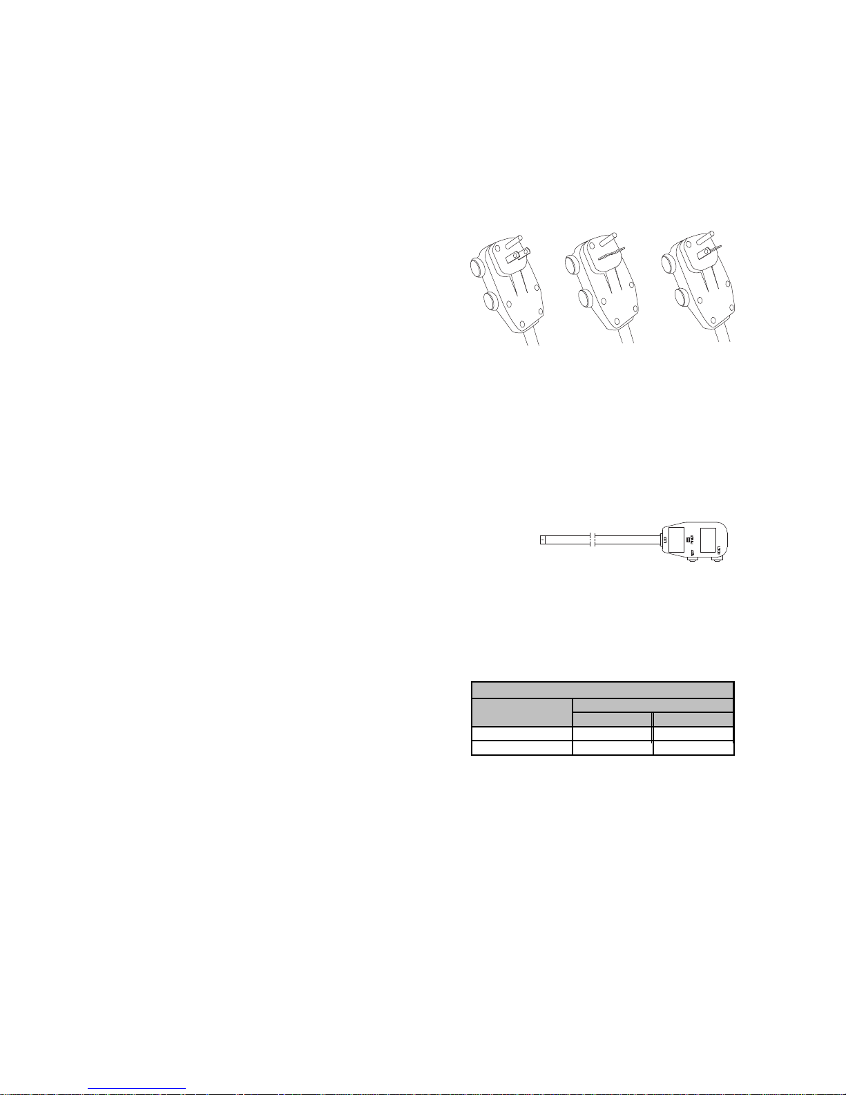
115V 230V 230V
15 amp 15 amp 20 amp
Figure 1
• LCDI or AFCI Power Cords - Underwrites Laboratories
and the National Electric Code (NEC) now require
power cords that sense current leakage and can open
the electrical circuit to the unit on units rated at 250
volts or less. In the event that unit does not operate,
check the reset button located on or near the head of
the power cord as part of the normal troubleshooting
procedure.
1
IMPORTANT NOTE TO THE OWNER
This equipment is to be serviced by professionally trained
personnel only. If this equipment is improperly installed,
adjusted or altered by an unqualified person, a safety
hazard may result.
IMPORTANT NOTE TO THE SERVICER
Read this manual and familiarize yourself with the specific
items which must be adhered to before attempting to
service this unit. The precautions listed in this manual
should not supersede existing practices but should be
considered as supplemental information.
Transportation Damage
All units are securely packed in shipping containers approved by the National Safe Transit Association. The carton
should be checked upon arrival for external damage. If
damage is found, immediately make a written request for
inspection by the carrier’s agent.
In the event of damage:
1. Note on the delivery receipt any visible damage to
shipment or container.
2. Notify carrier promptly and request an inspection.
3. File the claim with the following supporting documents
within the six month statute of limitations.
a. Original Bill of Lading, certified copy, or indemnity
bond.
b. Original paid freight bill or indemnity.
c. Original invoice or certified copy, showing trade and
other discounts or reductions.
d. Copy of the inspection report issued by carrier’s
representative at the time damage is reported to the
carrier.
The carrier is responsible for making prompt inspection of
damage and for a thorough investigation of each claim. The
distributor or manufacturer will not accept claims from
dealers for transportation damage.
Unpacking The Unit
1. Cut the carton banding and open the carton.
2. Remove the literature, hardware pack, upper styrofoam
shipping blocks, and styrofoam corner posts.
3. Remove the front assembly.
4. Lift the unit from the remaining carton.
5. Dispose of the cardboard and styrofoam at an approved
Recycle Center. Check all contents for damaged or
missing parts. In case of concealed damage, notify the
carrier as soon as possible—preferably within 5 days.
Refer to step 3 of the Transportation Damage section if
damage or missing parts are noted.
Operating Instructions
Check the data specification plate and ensure the proper
voltage and current rating for the type of power plug on the
unit is available. DO NOT REMOVE THE GROUNDING
PRONG FROM THE POWER CORD. See Figure 1 for the
types of acceptable plugs. Do not use an extension cord
for the installation of this product. Refer to the data
specification plate for electrical requirements.
Table 1
Operating Voltage
2
WARNING
To prevent electrical shock, property
damage, personal injury, or death, do not
remove grounding prong from plug. Follow
all operating instructions.
Installation Instructions
To ensure that the unit operates safely and efficiently, it must
be installed, operated, and maintained according to these
installation and operating instructions and all local codes
and ordinances, or, in their absence, with the latest edition
of the National Electrical Code. The proper installation of this
unit is described in the following sections. Following the
steps in the order presented should ensure proper installation.
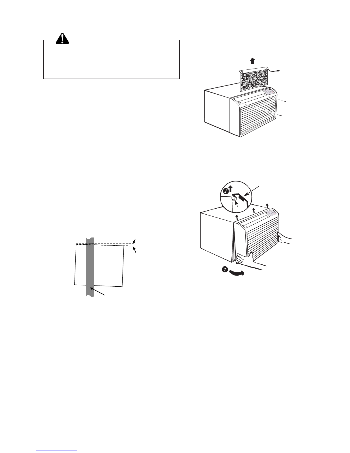
SLEEVE INSTALLATION
In order for condensate water to drain properly inside the unit,
the sleeve must be installed properly:
• Level from right to left.
• A slight downward pitch from the indoor side to the
outdoor side as shown in Figure 3.
Refer to the Installation Instructions supplied with the wall
sleeve for a complete description of the installation procedure.
NOTE: Wall sleeve (PBWS01A ) is not shipped with chassis
and must be purchased separately.
Wall
Sleeve
Outside
Wall
OutsideInside
Level
1/4 Bubble
Tilt To
Outside
Figure 2
CHASSIS INSTALLATION
1. Remove front grille. See Figure A.
Lift up on
Filter Handle
Figure A
The front grille can be removed for more thorough cleaning
or to make the model and serial numbers accessible. To
remove, pull the filter out and remove the two grille screws.
Grille
Tab
Pull the grille out from the bottom and lift up from the tabs
on the top of the case.
2. Remove the grounding screw and wire next to the
grounding symbol on right side of chassis control panel
(Figure 3). Attach other end of ground wire to the hole
in the bottom right side of the sleeve with #8 x 3/8” blunt
point sheet metal screw. The hole on the sleeve is
indicated by grounding symbol on the sleeve. Slide
chassis part of the way into the sleeve and reattach the
ground wire back to the hole on the right side on the
control panel area next to the grounding symbol.
 Loading...