

Page 1
Page 2

Contents
Safety Precautions .......................................................................................... 1
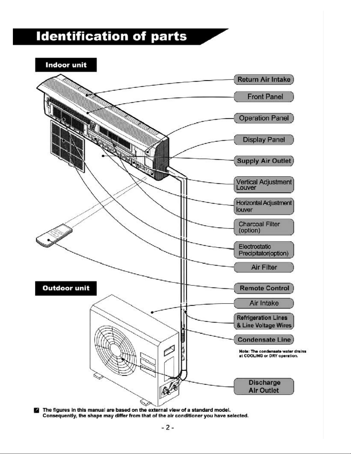
Identification of parts ...................................................................................... 2
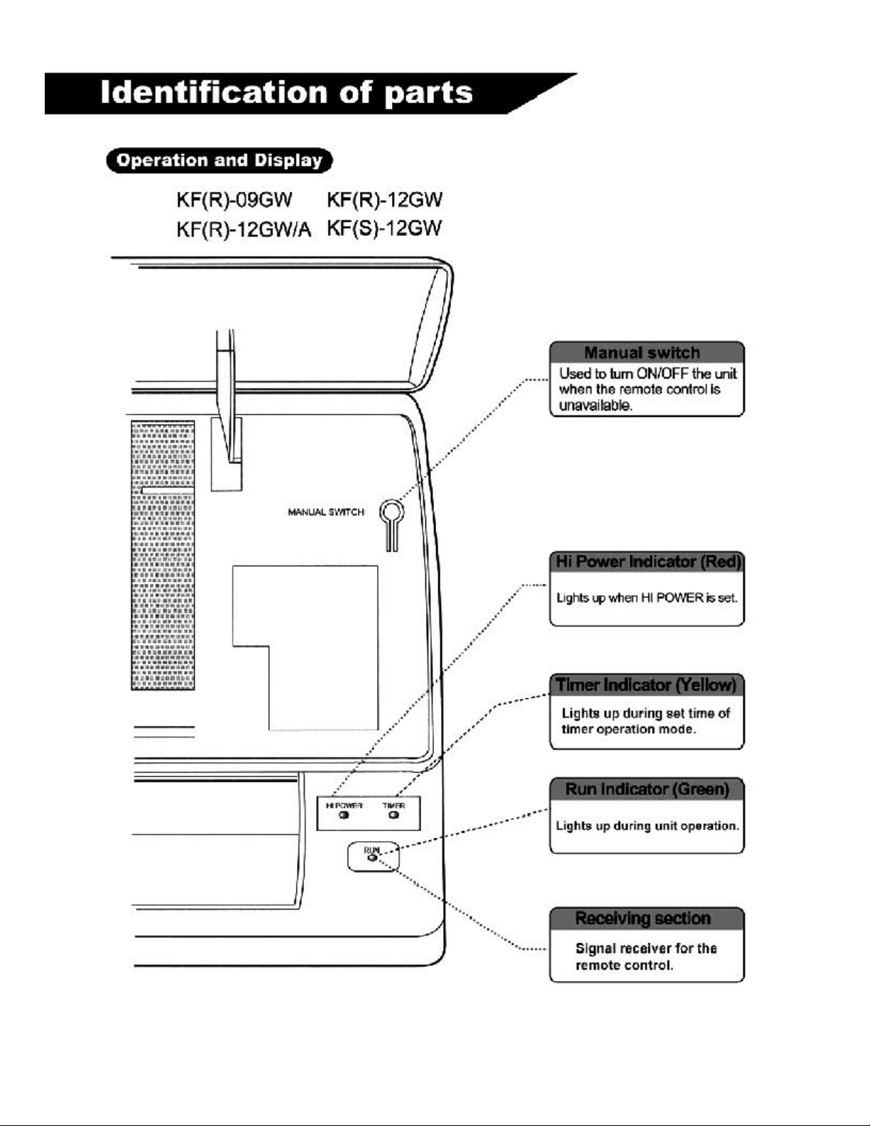
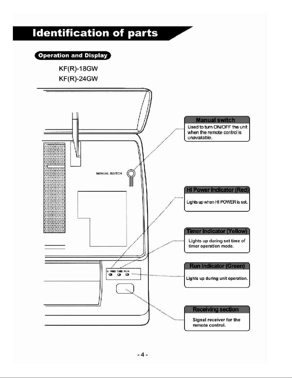
Indoor Unit / Operation and display ............................................................. 3,4
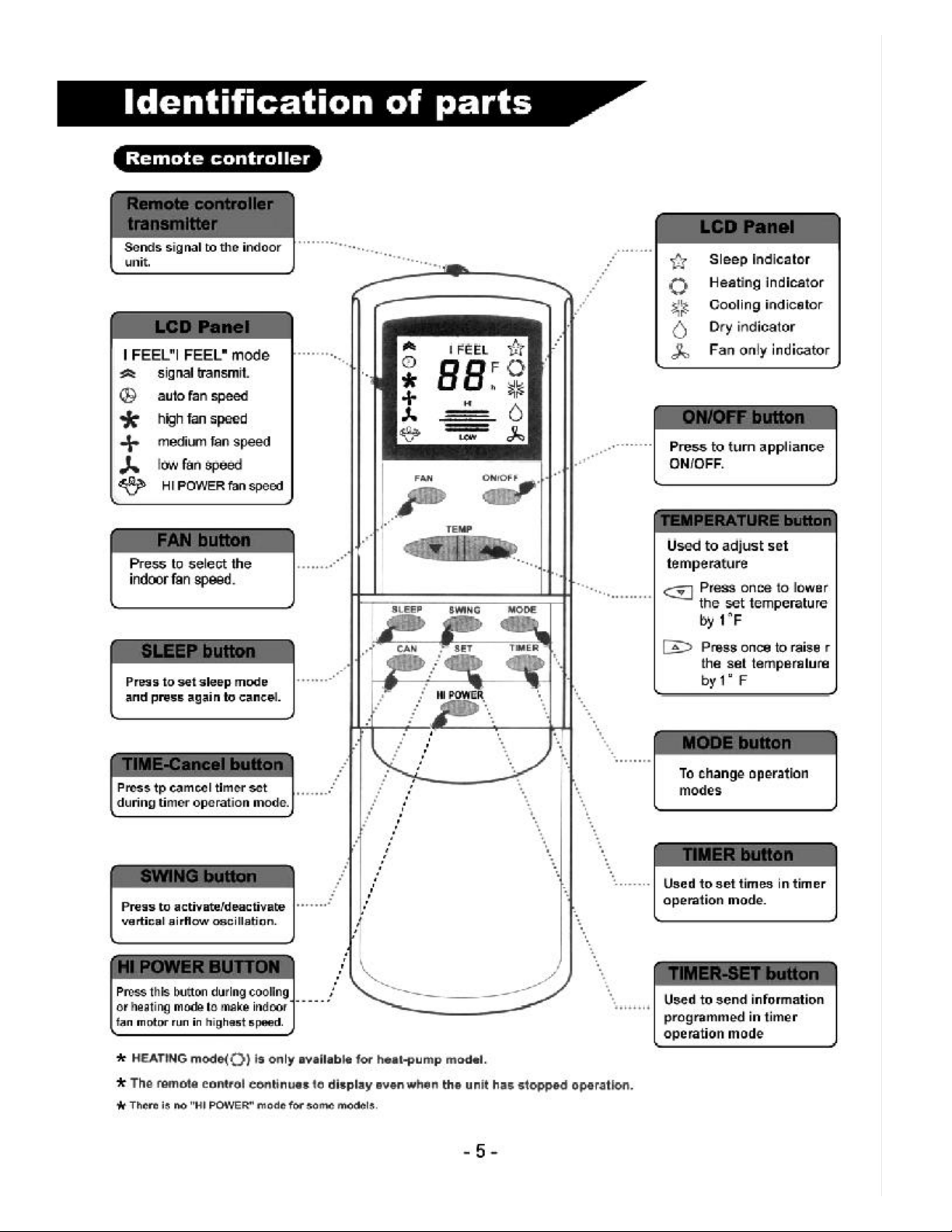
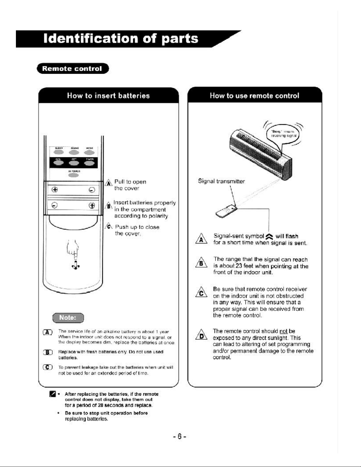
Remote controller ......................................................................................... 5,6
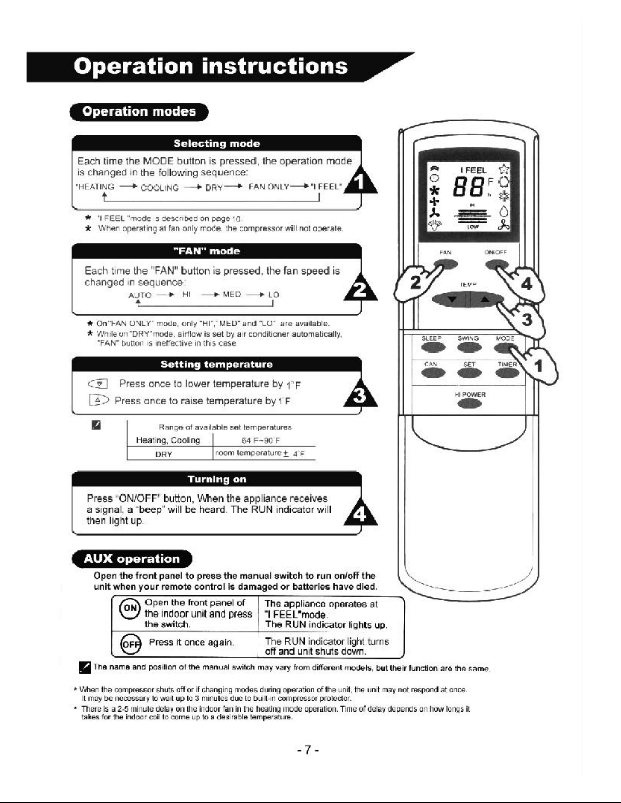
Operation instructions / Modes....................................................................... 7
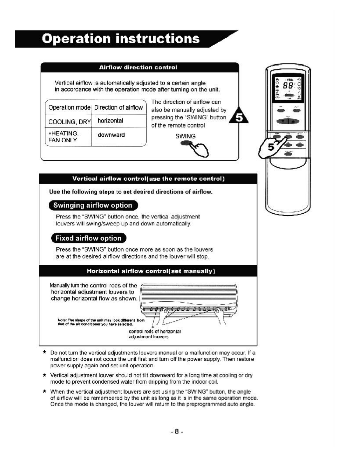
Air flow direction control................................................................................. 8
“I FEEL” mode ................................................................................................. 9
Timer operation mode ................................................................................... 10
Sleep operation mode .................................................................................... 11
Maintenance .................................................................................................. 12
Protection ...................................................................................................... 13
Refrigeration cycle ........................................................................................ 14
Specifications................................................................................................ 15
Installation instructions ........................................................................... 16-24
System start up Procedures Electrical Schematics ................................ 25-27
WARNING ....................................................................................................... 28
Troubleshooting ........................................................................................ 29,30
Warranty......................................................................................................... 31
Page 3
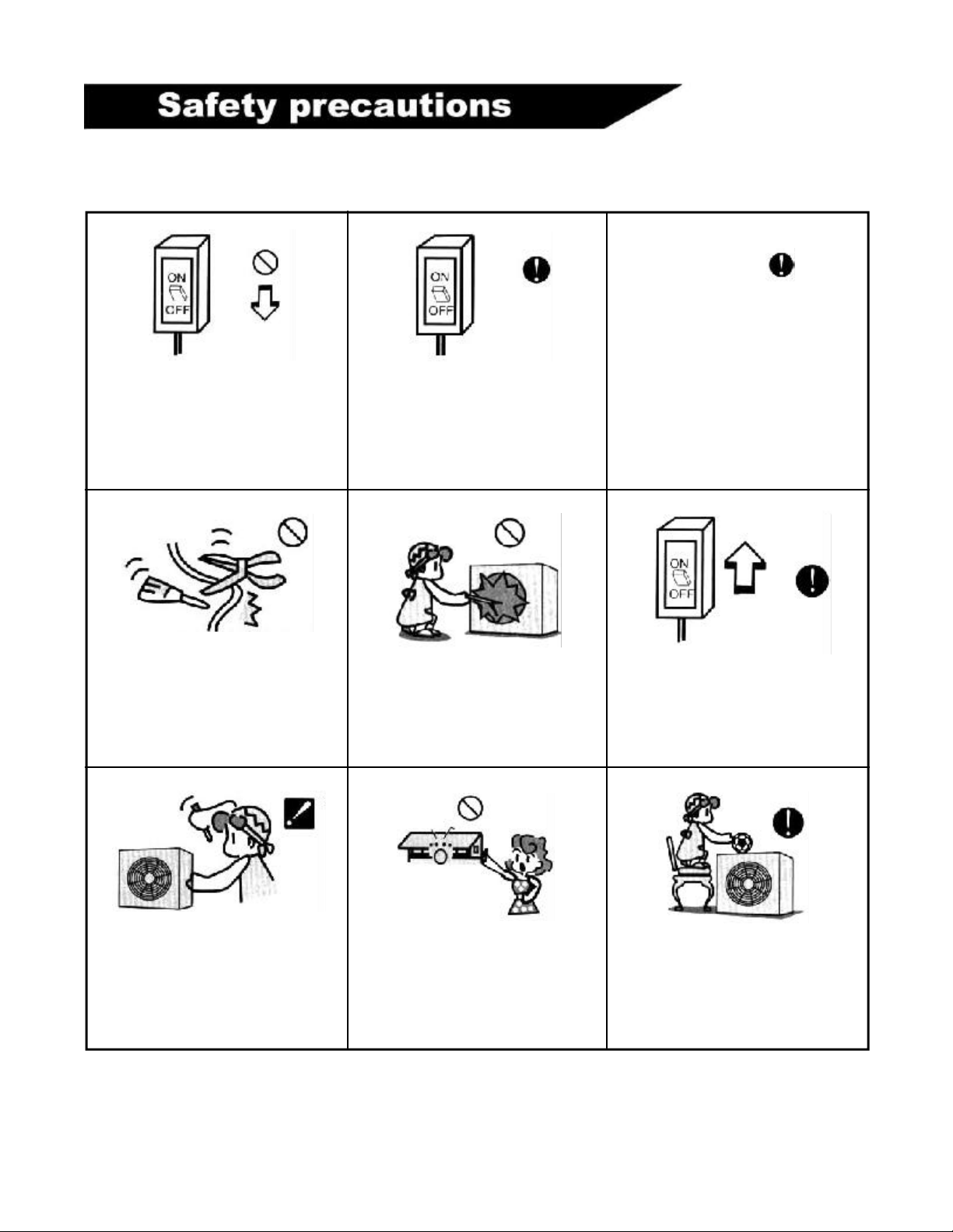
Use 230V/60Hz or 115V/60Hz
power supply only .
Do not turn off the power supply circuit breaker or pull out the unit power
cord during unit operation. This may
cause electrical hazards and/ or a fire.
Power supply wires must be located
in areas where they will not be damaged or cut.
Keep the power supply circuit breaker
and power plug free from any type of
debris. If using a power supply cord, be
sure to connect to plug firmly. This will
minimize the risk for electrical shock or
any other type of electrical hazard.
Never insert any type of object into
the outdoor unit fan. Because the fan
rotates at a high speed, this may
cause injury.
Depending on the electrical specifications of your unit, use only 230V/
60Hz or 115V/60Hz power supply.
Failure to do so may result in electrical problems or hazards.
Be sure that the indoor and outdoor
units are not in operation when disconnecting the power supply to the unit.
Any type of repairs or maintenance
done to the units must be done by a
professionally licensed contractor.
Any unqualified person should not attempt to repair the units themselves.
Be sure that your hands are not wet
when touching any of the operation
buttons on the indoor unit.
- 1 -
Be sure that the outdoor unit is free
and clear of any debris around the outside of the unit. Do not place or lean
any items on the unit.
Page 4
Page 5
- 3 -
Page 6
Page 7
Page 8
Page 9
Page 10
Page 11

- 9 -
Page 12

- 10 -
Page 13

Page 14

Page 15

Page 16

- 14 -
Page 17

Specifications
PERFORMANCE RATINGS
MODEL
Capacity Cooling [BTU/h]
Capacity Heating [BTU/h]
SEER
Moisture Removal[Pts/h]
Air Flow
Sound Rating Indoor dB
Sound Rating Outdoor dB
Operating Range - Cooling [F]
Operating Range - Heating [F]
ELECTRICAL DATA
Power Source
Min. Ampacity [A]
Cooling Watts Amps
Heating Watts Amps
Max TD Fuse/Breaker [A]
KFS-12G
12000
12000
10.5
2.9
340/450/520
<42
<52
60 to 109
28 to 75
115-60-1
15
1440 / 11.7
1420 / 10.8
28
KFR-12G
12400
12800
10.5
2.9
340/450/520
<42
<52
60 to 109
28 to 75
230/208-60-1
10
1230 / 5.3
1300 / 5.7
15
KFR-18G
18500
18800
10.2
3.1
690/810/900
<44
<58
60 to 109
28 to 75
230/208-60-1
15
1870 / 8.1
1890 / 8.2
22
KFR-24G
23100
23266
10.4
5.2
890/1100/1200
<45
<59
60 to 109
28 to 75
230/208-60-1
15
2323 / 10.1
2379 / 10.3
27
REFRIGERANT LINES
Connections
Liquid Line OD [in]
Suction Line OD [in]
Mac line Length [ft]
Max Height Difference [ft]
DIMENSIONS & WEIGHTS
I
NDOOR SECTION
WxHxD [in]
Shipping Weight [lbs]
OUTDOOR SECTION
WxHxD [in]
Shipping Weight [lbs]
Refrigerant Charge [lbs]
Specifications are subject to change without prior notice. Visit our website - www.soleusair.com
Flare
1/4
1/2
49
16
KFS-12GW
24x8x5
22
KFS-12GWH
31x22x10
73
2
Copyright 2003 Soleus International Inc.
Flare
1/4
1/2
49
16
KFS-12GW
24x8x5
22
KFS-12GWH
31x22x10
73
2.1
Flare
1/4
1/2
49
16
KFS-12GW
42x14x11
29
KFS-12GWH
38x28x15
115
2.9
Flare
3/8
5/8
49
16
KFS-12GW
46x15x11
31
KFS-12GWH
38x39x15
143
4.8
- 15 -
Page 18

- 16 -
Page 19

Installation instructions
Select the installation locations
Indoor unit installation location:
l
Locate indoor unit so that there is not obstruction near the supply air or return air
outlets.
l
The wall that the indoor unit hangs on must be free from internal obstructions to
facilitate a clear hole for the refrigeration lines and condensate line to go through.
l
Proper clearances must be maintained to ceilings and walls per instructions on page 16.
l
Easy access must be maintained for removal of the air filter.
l
Indoor unit and remote control must be at least 3 feet from televisions, radios, etc.
l
Indoor unit and remote control must be kept out of direct sunlight and/or fluorescent
lighting.
l
The wall that the indoor unit hangs on must strong enough to bear the weight of the
unit to ensure quieter operation.
Outdoor unit installation location:
l
Outdoor unit location must be well ventilated. Avoid installing where any type of flammable
gas could leak.
l
Proper clearances must be maintained per instructions on page 16.
l
The maximum length for refrigeration lines is 49 ft. For refrigeraton lines exceeding 23ft. an
additional .75 pounds must be added per 3.5 feet.
l
The Maximum height between indoor and outdoor units in 25ft. If the outdoor unit is located
above the indoor unit more than 4 ft., a suction line oil trap must be installed.
l
The outdoor unit must not be located in environments that have high contents of acidic
substances, vulcanized gasses, or high salt contents in the air.
l
The outdoor unit must not be located near locations where dirt, mud, or debris can be caked
onto the outdoor coil or unit.
l
The foundation that the outdoor unit sits on must be solid and sound so as to decrease noise vibration.
l
No obstructions should be placed around the outdoor unit.
Indoor unit installation
1. Installing the mounting plate
l
Hold mounting plate on the wall where unit will be located. Using a level or plumb line,
ensure that the plate is level. Once the plate is level, mark holes that will be used to
hold plate on the wall.
l
Remove plate and drill marked hole at a depth of 1.75 inches.
l
Insert the screw plugs into the holes and affix the mounting plate using the tapping screws.
l
Once mounting plate is securely fastened to the wall, then locate an area on the wall for the access hole for the refrigeration
Note: The shape of your mounting plate may be different from
the one above, but installation method is simllar.
line/condensate line/wiring bundle.
2. Access hole for refrigeration lines/condensate drain line/wiring bundle.
l
These directions must be followed at least for the condensate drain line. There must
be rear access for the condensate drain line to drain properly from the unit.
l
Decide on a location for the access hole according to the location of the unit.
l
Drill an approximately 2.5 inch hole, making sure that there is a tilt downward of a 1/4
inch. This will ensure that proper drainage is maintained for the condedsate drain line.
(If you are not using rear access for the refrigeration lines and wiring, hole will does
not need to be as large.)
l
It is recommended that a wall sleeve of some sort (i.e. PVC pipe) be used to keep the hole neat and tidy.
- 17 -
Page 20

Installation instructions
3. Indoor unit refrigeration line installation
l
The refrigeration lines and wiring can be routed to the outdoor unit in a number of ways (left or right from the back of the
unit), by using the cut-out access pieces on the casing of the unit.
l
Bend the refrigeration lines carefully to the required positon in order to be aligned with the drilled hole.
piping direction
cut-out
access
Note:
Saw the cut-out access off
along the side of the casing
l
After connecting refrigeraton lines (see directions below), install the condensate drain line (see page 21+24 for detailed
instructions on connecting condensate drain line). Then connect all wiring (see pages 25-27 for detailed instructions on
wiring). After all connections are made, bundle the refrigeration lines, wiring, and condensate drain line together using a
thermal insulation and vinyl/duct tape.
Refrigeration lines insulation:
l
It is important that both the liquid and suction
refrigeration lines are individually insulated to ensure
that they do no sweat and also to maintain proper unit
capacities. This is necessary since the refrigeration is
metered from the outdoor unit and will produce condensation on both refrigeration
lines if not proper insulated.
When installing the refrigeration lines at the directions 1, 2 or 4,
saw the corresponding cut-out piece off the indoor unit casing.
Refrigeration lines/Condensate drain line/wiring bundle thermal insulation:
l
Place the condensate drain line under the refrigeration lines.
l
Insulation material should be a polythene foam that is approximately a 1/4
inch wall thickness.
l
Condensate drain line should have a downward slope at all times to ensure
proper drainage. Do not allow the drain line to be twisted, horizontal or the
end of the line be immersed in water. If an extension is added to the drain line, make sure that it is also properly insulated.
Connection of refrigeration lines:
l
Do not use contaminated or damaged copper tubing for refrigeration lines. If any of the tubing,
evaporator or condenser coils have been exposed to the air for more that 15 seconds, it is
important that they are vacuumed and purged with field-supplied refrigerant. Do not remove
plastic or rubber plugs and brass nuts from the valves, fittings, tubing, or coils until they are
ready to be connected.
l
Use proper tubing cutters to cut the refrigeration lines, advancing the blade of the tubing cutters
slowly. Extra force or improper cutting will cause tubing distortion and also extra burring.
l
Once refrigeration tubes are cut, remove burrs from cut edges with a remover. This will avoid
unevenness on the flare faces, which could cause a gas leak. Hold the ends of the pipes
downward to prevent metal from going into the tubes.
l
Insert the flare nuts, mounted on the connection ends of both the indoor and outdoor units onto
the ends of the copper tubing.
l
The length of the pipe protruding from the face of the flare die is determined by the particular flaring tool that will be
used.
l
Fix the pipe firmly on the flare die. Match the centers of both the flare die and the flaring punch, and then tighten the
flaring punch fully.
l
Once flaring is complete, connection of the tubing is ready. Align the center of the tubing and tighten the flare nuts
using a torque wrench.
- 18 -
Page 21

- 19 -
Page 22

Mounting the Indoor unit to the Mounting Plate:
Hook
l
Hook the indoor unit onto the upper portion of the mounting plate by connecting the hooks at the
rear top of the indoor unit with the upper edge of the mounting plate.
l
To ensure that the hooks are properly seated on the mounting plate, check if the unit can slide
by moving it to the left and right. If the unit moves, it is not properly seated.
l
A unit support plate in the mounting plate can be used if the unit is on a slanted wall and can
also be used to ease the connection of the refrigeration lines.
Hook
l
Affix the screw underneath the unit to the mounting plated after completed with installation.
Suppport plate
Connection of condensate drain extension line:
l
Place glue on the end of the drain line extension end.
l
Fully insert the end of the drain line to the extension line. Make sure it is properly inserted to no less than 3/8 of an inch so that water
does not leak from the hose.
- 20 -
Page 23

Installation instructions
Outdoor unit installation
1. Install the outdoor unit
l
Outdoor unit must be mounted on a solid, level foundation. If possible, affix unit using bolts to the foundation.
l
If installing on a wall or structure, be sure that construction of the wall or structure can support the weight of the unit and
that consideration is given to the integrity of the construction. Since the unit can vibrate during operation, movement of
sound of the unit should be considered when installing the unit.
l
Since the unit discharges air during operation, plants or other obstruction should be free and clear of the unit to ensure
proper operation.
l
Owners should advised to avoid lawn mowers or other machinery discharge toward the unit, as debris can damage the
finned coil surfaces and reduce effciency of the unit.
2. Outdoor unit refrigeration line connection
l
Remove the valve caps at the outdoor unit where f\refrigeration tubing will be connected.
l
Connect the refrigeration tubing using flaring techniques described earlier
in the indoor unit installation. Be sure to use required torque.
Attention
l
A baffle is needed when installation is in locations near the sea or areas
with strong winds.
l
Be sure that unit airflow is not obstructed in any way or that reciculation of
discharge air does not occur.
- 21 -
Page 24

Installation instructions
3. Wiring connection
l
Remove the electrical cover of outdoor unit (1 screw).
l
Connect wires as shown below in the illustrations.
Outdoor unit terminal block
Heat Pump
Connect to Power Supply
The conduit should not be loosened after being fixed, otherwise, it may cause abnormal noise when the unit is
running.
Number 14 wire should be used for KFR-18GW.
Number 12 wire should be used for KFR-24GW.
Number 14 wire should be used for KFR-09GW, KFR-12GW/A.
Number 16 wire should be used for KFR-12GW.
Power supply inter connecting
conductors (in conduit A)
( to the indoor unit)
Control inter connecting
conductors(in conduit B)
( to the indoor unit)
- 22 -
Page 25

Installation instructions
System Start Up and Charge Adjustment Procedures
Leakage check
Properly check refrigeration tubes and connections for any leaks prior to system start up procedures.
NOTE:
A is the low-pressure valve
B is the high-pressure valve
C and D are the joints of connecting pipes
of indoor unit.
Air exhaust
The outdoor unit is supplied with a R-22 charge sufficient for 15 feet of refrigeration tubing.
The outdoor unit’s liquid and suction valves are closed to contain the charge within the
unit. The recommended procedures for charge adjustments are as follows:
Additional Charge Needed for Refrigeration lines over 15 feet
Liquid Line O.D. (Inches) Additional R-22 (oz / ft)
1/4
3/8
1. After connecting the refrigeration tubing to the indoor and outdoor units. connect a
vacuum pump to the refrigeration valve service ports.
2. Evacuate through the liquid and suction valve service ports to 500 microns or less for a minimum of 30 minutes. Close
the valves to the pump and monitor the vacuum for 15 minutes. The vacuum should not rise above 800 microns.
3. If a vacuum of 500 microns cannot be obtained, or if it rises ablve 800 microns over the 15 minute period, discontinue
evacuation, pressurize the system with nitrogen and look for leaks. Repair any leaks that are found and repeat step 2.
4. Close the valves to the vacuum pump, turn the pump off, and disconnect it from the refrigerant valve service ports. Open
the liquid and suction service valves fully, releasing the R-22 into the system. Connect the service gauges to the refrigerant
valve service ports.
5. Set the indoor remote control to cool mode and ensure proper operation. Allow unit to run for a period of 10 minutes to
allow system pressures to stabilize.
Make sure that proper pressures are observed.
*
Check proper temperatures in space, to ensure temperatures match those on remote control.
*
Check condensate drain hose for proper drainage.
*
Check for any abnormal vibration noises and correct as needed.
*
Check for any signs of refrigerant leakage.
*
6. Set the indoor remote control to heat mode and ensure proper operation. Allow unit to run for a period of 10 minutes to
allow system pressures to stabilize. Fllow same checkouts as cool mode.
.22
.58
- 23 -
Page 26

HOW TO INSTALL DRAIN ACCESSORIES
There will be some water dripping from the condenser when the heat pump is working during the heating mode.
Two drain caps, a drain elbow with rubber collar and a plastic hose (5/8” x 6”) are supplied for user’s choice.
INSTALLATION STEPS:
(1) Observe the drainage flow of the three drain holes on the base while pouring water into the condensing unit
evenly around the condenser. (Figure 1)
(2) Connect the drain elbow and the plastic hose. (Figure 2)
(3) Insert the drain elbow connected with the drain hose into the hole which has the largest drainage flow and
rotate it to the wall side of the building in order to make the drainage flow against the wall. The other two holes
of the base should be stopped by using the two drain caps. (Figure @)
NOTE:
If the drain hole inserted with the drain elbow is not at the desired location, adjust the level of the condensing unit
slightly, and then reinstall the accessories according to the above steps.
- 24 -
Page 27

- 25 -
Page 28

- 26 -
Page 29

Page 30

!
WARNING
USE COPPER WIRES ONLY FOR POWER SUPPLY.
!
WARNING:RISK OF ELECTRIC SHOCK CAN CAUSE INJURY OR DEATH.
!
DISCONNECT ALL ELECTRIC POWER SUPPLIES BEFORE SERVICING.
DURING CONNECTION OF THE REFRIGERATION TUBES, IF EXCESSIVE
!
TORQUE IS IMPOSED ON FLARE NUTS, SERVICE VALVE ON DISCHARGE
LINE MAY BE DAMAGED. WHEN TIGHTENING FLARE NUTS OR NARROW
PIPE, TORQUE SHOULD BE ADJUSTED BETWEEN 13.7~18.6N.M
(140~190GF.CM).
DO NOT PUT INDOOR UNIT IN LOCATIONS WHERE IT MAY GET WET.
!
ELECTRICAL INSTALLATION MUST BE IN ACCORDANCE WITH LOCAL AND
!
NATIONAL ELECTRICAL CODES.
THE INSTALLATION OF THESE UNITS REQUIRES QUALIFIED PERSONNEL.
!
CERTIFIED(APPROVED) POWER SUPPLY CONDUCTORS MUST BE USED.
!
AN INDEPENDENT BRANCH CIRCUIT BREAKER MUST BE USED.
!
MAXIMUM INTER CONNECTING WIRE LENGTH SHOULD NOT EXCEED
!
11.3M (37FT.)
REFRIGERATING PIPE LENGTH MUST BE LIMITED BETWEEN 4~10M
!
( 13FT~33FT.) IF THE LENGTH EXCEEDS 7.62M(25FT.), THE COOLING
(OR HEATING) CAPACITY MAY BECOME IMPAIRED.
DIFFERENCE IN HEIGHT BETWEEN INDOOR AND OUTDOOR UNIT SHOULD
!
NOT EXCEED 7M(26 FT.).
- 28 -
Page 31

- 29 -
Page 32

Troubleshooting
RUN light blinks Defect What to check
Open circuit or short circuit of room
1 time
2 times
3 times
Abnormality of room temperature
sensor.
Abnormality of defrost sensor.
Abnormality of indoor fan motor.
•
temperature sensor.
Incorrect connection of the sensor.
•
Open circuit or short circuit of defrost
•
sensor.
Incorrect connection of the sensor.
•
Indoor fan motor is defective.
•
Bad connection to motor.
•
4 times
Continuous
blink
Abnormality of outdoor unit.
No defect-unit in defrost mode.
Compressor is defective.
•
Refrigerant is low.
•
Capacitor is defective.
•
- 30 -
 Loading...