

Soleus Air KFHHP-12, KFIHP-09, KFIHP-09OD, KFHHP-12OD User Manual
1
Summary and features
Model Remarks
KFIHP-09
SOLEUSAIR
1Ph,115V,60Hz,R410A
KFHHP-12 1Ph,208-230V,60Hz,R410A
2
COOLING HEATING
10400 12800
6.4 7
Model of I ndoor Unit
Fan Motor Speed ( r/min)
(H/M/L)
Output of Fan Motor (w)
Input Power of Heater (w)
Fan Motor Capacitor (uF) 1.0
Fan Motor RLA(A) 0.14
Fan Type-Piec e
Diameter-Length (in) 3.8-23
Evaporator
Pipe Diameter (in) 0.28
Row-Fin Gap(in) 2-0.055
Coil length (l) x height (H) xcoil
width (L)(in)
Swing Mot or Model
Output of Swing Mot or ( W )
Fuse (A)
Sound Pr essure Lev el dB ( A)
(H/M/L)
Dimension (W/D/H)( in)
Dimension of Pack age
(W/D/H)( in)
Net Weight /Gross Weight (lb)
Model
KFIHP-09
Function
Rated Voltage 115V
Frequency(Hz) 60HZ
Rated Capacity (Btu/h)
Rated Input (W) (High/Standard) 1200/730 1400/800
Rated Current (A)
Air Flow Volume (m
3
/h) (H/M/L)
600
Dehumidifying Volume (l/h) 1.2
Indoor
unit
KFIHP-09ID
1160/1010/890
/
Cross flow fan – 1
φ
Aluminum fin-co pper tube
Φ
2
PCB3.15A transformer0.2A
18.7/27.6
40/ 36/ 33
32.67×8.86×11.22
33.66×10.7×13.22
Specifications and technical parameters
2
14
22.83x9x1
MP28VA

Model of O utdoor Unit
Compressor Manufact ur er /tr ademark
Compre ssor Model
Compre ssor Type
L.R.A . (A)
Compressor RLA ( A)
Compressor Power Input(W)
Overload P r otect or
Thr ottling Met hod
Star ting Method
Wor king Temp Range (ć)
Condenser
Pipe Diameter (in)
Rows-Fin Gap(in)
Coil
length
(l)xheight
(H)xcoil
width
(L)(in(i(
Fan Motor Speed (rpm)
Out put of Fan Motor ( W)
Fan Motor RLA(A)
Fan Mot or Capac itor (uF)
Air Flow Volume of Outdoor Unit
Fan Type-Piece
Fan Diameter (in)
Defr osting Method
Climate Type
Isolation
M oisture Protection
Permissible Ex c essive Operat ing
P re ssur e for the Disc harg e
Permissible Excessive Operating
Sound Pr essure Lev el dB ( A) ( H /M /L)
Dimension (W/D/H)( in)
Dimension of Pac k age ( W/D/ H) ( mm)
Net Weight /Gross Weight (lb)
Refrigerant Charge (oz)
Length (ft)
Gas additional charge(oz/ft)
Liquid Pipe (mm)
Φ6(1/4”)
Gas Pipe (mm)
Φ12(1/2”)
Height (ft) 39
Length (ft) 66
R410A / 42
88.18/99.2
34.6X14.2X23.2
33.38X12.6X21.27
Outdoor
unit
Connec
tion
Pipe
Outer Diameter
Max Distance
T1
Auto defrost
15.75
55
1.2
3.8
IP24
33
30
830±20
25.4X20X1.73
2-0.05
960
3.92
Int11l-3979
0.37
Aluminum fin-c opper tube
KFIHP-09OD
C-6RZ092H1AB
SANYO
Twin rotory
-7ćİTİ43
ć
Capillary t hrottling
Tr ansducer star ting
0.22
26
1800
Axial fan –1
2.5
0.3
I
If there are any changes in the specifications and parameters in the above table, Please refer to the nameplate of the unit.
SOLEUSAIR

2
COOLING HEATING
13200 15900
1450/1100 1500/1200
5 5.45
Model of I ndoor Unit
Fan Motor Speed ( r/min)
(H/M/L)
Output of Fan Motor (w)
Input Power of Heater ( w)
Fan Motor Capacitor (uF)
Fan Motor RLA(A)
Fan Type-Piec e
Diameter-Length (in)
Evaporator
Pipe Diameter (in)
Row-Fin Gap(in)
Coil length(l) x height (H) xcoil
width (L)(in)
Swing Mot or Model
Output of Swing Mot or ( W )
Fuse (A)
Sound Pr essure Lev el dB ( A)
(H/M/L)
Dimension (W/D/H)( in)
Dimension of Pack age
(W/D/H)( in)
Net Weight /Gross Weight (lb)
Model
KFHHP-12
Function
Rated Voltage 208V230V
Frequency(Hz) 60HZ
Rated Capacity (Btu/h)
Rated Input (W) (High/ Standard)
Rated Current (A)
Air Flow Volume (m
3
/h) (H/M/L)
600
Dehumidifying Volume (l/h) 1.2
Indoor
unit
KFHHP-12ID
1350/1200/1110
22
/
1
0.152
Cross flow fan – 1
φ3.63—24.3
Aluminum fin-co pper tube
Φ0.27
2-0.05
26.8×12.76×1.5
MP28EA
2
Controller 3.15 tr ansfor mer0. 2
24.3/33
43 / 40 / 39
32.7×8.86×11.2
34.4×12.3×14.6
Specifications and technical parameters
6
Model of O utdoor Unit
Compressor Manufact ur er /tr ademark
Compre ssor Model
Compre ssor Type
L.R.A . (A)
Compressor RLA ( A)
Compressor Power Input(W)
Overload P r otect or
Thr ottling Met hod
Star ting Method
Wor king Temp Range (ć)
Condenser
Pipe Diameter (in)
Rows-Fin Gap(in)
Coil
length
(l)xheight
(H)xcoil
width
(L)(in(i(
Fan Motor Speed (rpm)
Out put of Fan Motor ( W)
Fan Motor RLA(A)
Fan Mot or Capac itor (uF)
Air Flow Volume of Outdoor Unit
Fan Type-Piece
Fan Diameter (in)
Defr osting Method
Climate Type
Isolation
M oisture Protection
Permissible Ex c essive Operat ing
P re ssur e for the Disc harg e
Permissible Excessive Operating
Sound Pr essure Lev el dB ( A) ( H /M /L)
Sound Power Level dB ( A) ( H/M/L)
Dimension (W/D/H)( in)
Dimension of Pac k age ( W/D/ H) ( mm)
Net Weight /Gross Weight (lb)
Refrigerant Charge (oz)
Length (ft)
Gas additional charge(oz/ft)
Liquid Pipe (mm)
Φ6(1/4”)
Gas Pipe (mm)
Φ12(1/2”)
Height (ft)
Length (ft)
R410A / 44
88.18/99.2
34.6X14.2X23.2
65
33.38X12.6X21.27
Outdoor
unit
Connec
tion
Pipe
Outer Diameter
Max Distance
T1
Auto defrost
15.75
55
1.2
3.8
IP24
33
30
830±20
25.4X20X1.73
2-0.05
960
3.92
Int11l-3979
0.37
Aluminum fin-c opper tube
KFHHP-12OD
C-6RZ092H1AB
SANYO
Twin rotory
-7ćİTİ43
ć
Capillary t hrottling
Tr ansducer star ting
0.22
26
1800
Axial fan –1
2.5
0.3
I
If there are any changes in the specifications and parameters in the above table, Please refer to the nameplate of the unit.
SOLEUSAIR
39
66
7
3
Dpoofdujpo!qjqf
boe! dpoofdujpo! xjsf
Bjs!Pvumfu
ü8ü
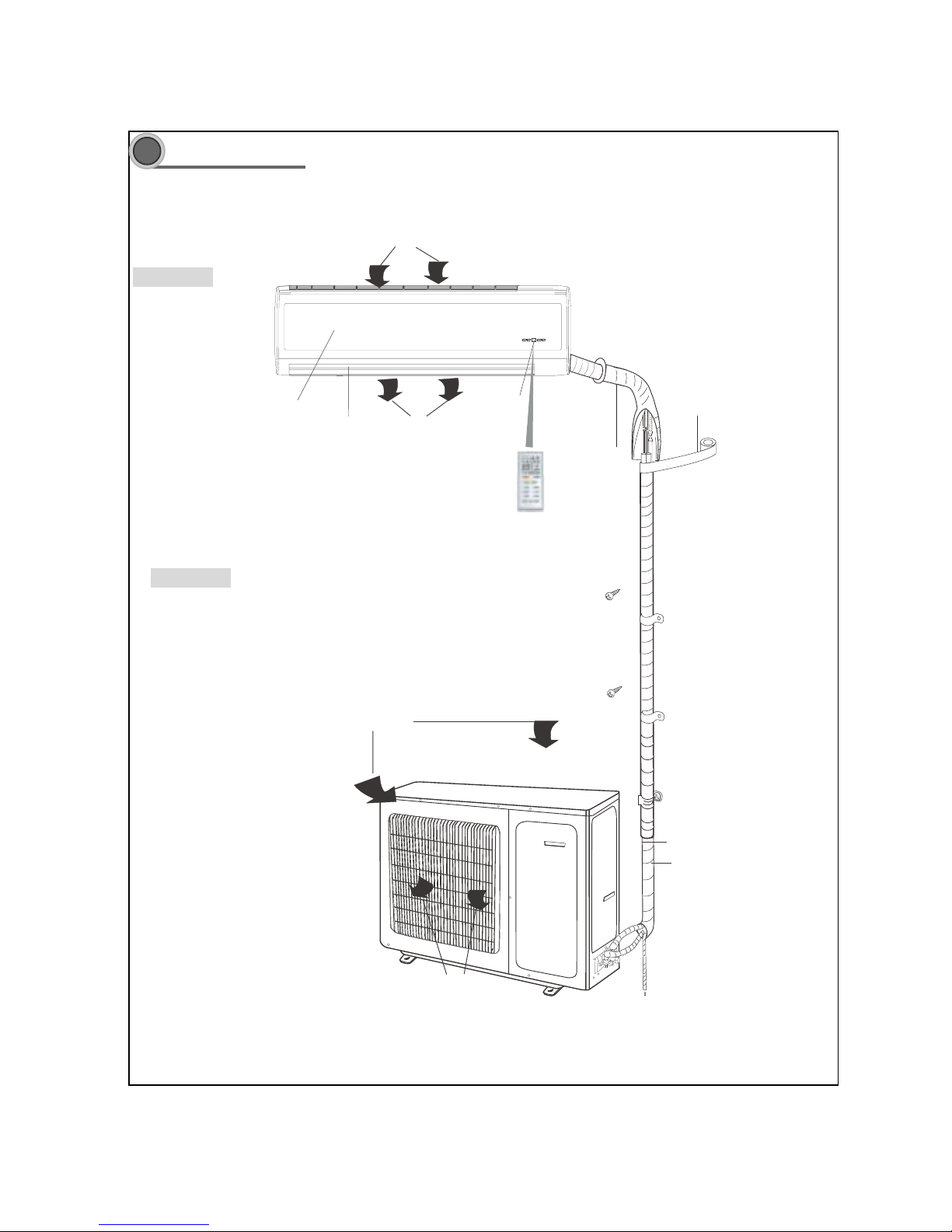
Part name
Indoor Unit
Outdoor Unit
Air inlet
Wireless remote controll
Front panel
Guide louver
Air outlet
Receiving window
LED board
wrapping tape
Air inlet
Air outlet
Drainage hose
Connecting pipe and connection wire
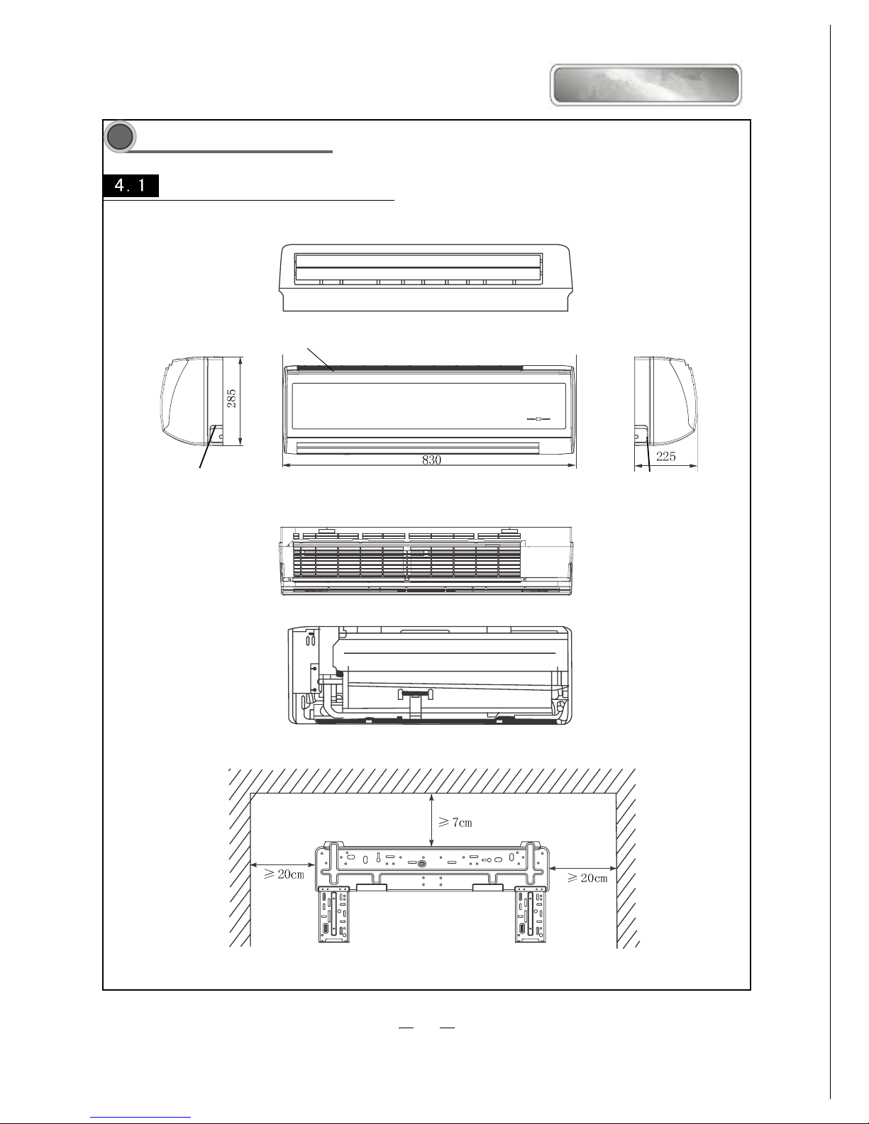
4
Air inlet grill
Right piping hole
Left piping hole
Top view
Unit˖mm
Rear view
Wall-mounting plate
Overall and Installing Dimension
UOverall and Installing Dimension of Indoor Unit
SOLEUSAIR
9
U
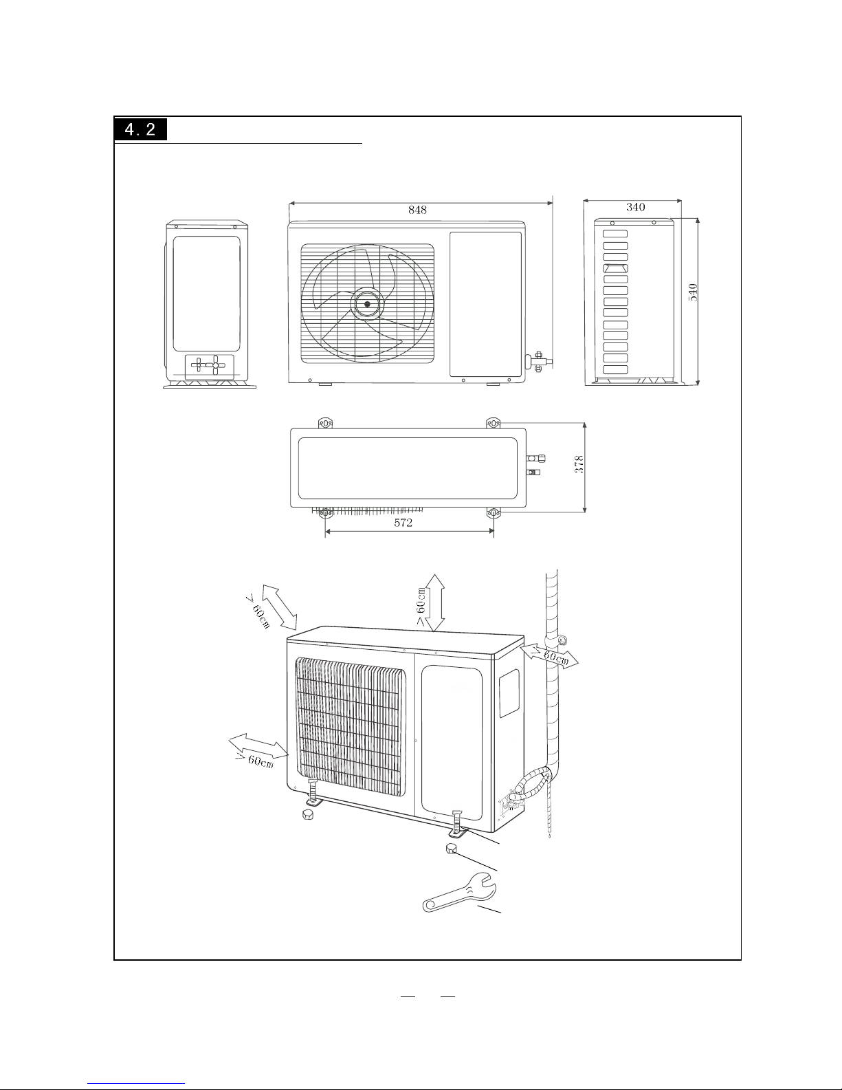
Overall and Installing Dimension of Outdoor Unit
Nut
Bolt
Wrench
Unit: mm
10
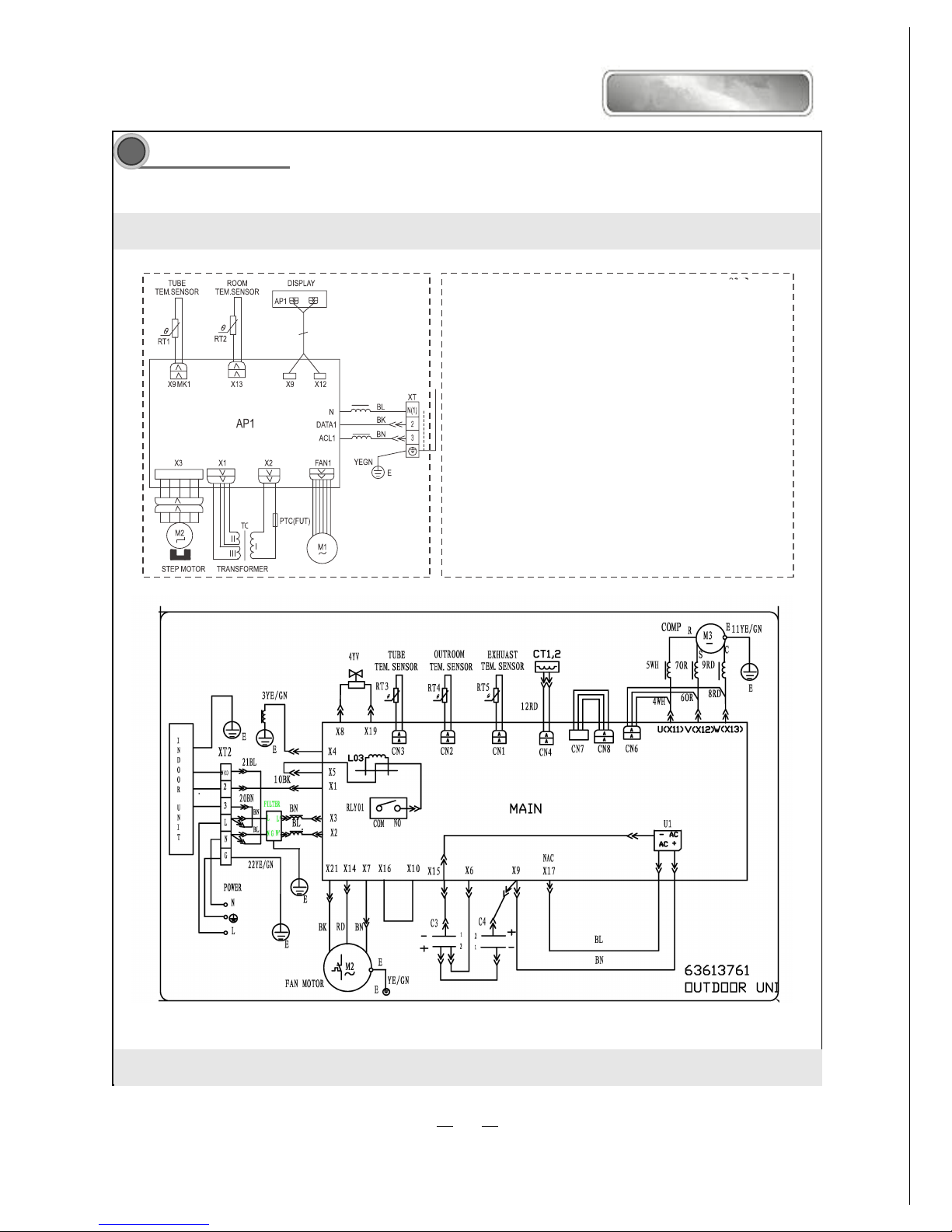
INDOOR UNIT
Circuit Diagram
These circuit diagrams are subject to change without notice. Please refer to the ones stuck on the machines.
SOLEUSAIR
KFIHP-09
11
INDOOR UNIT OUTDOOR UNIT
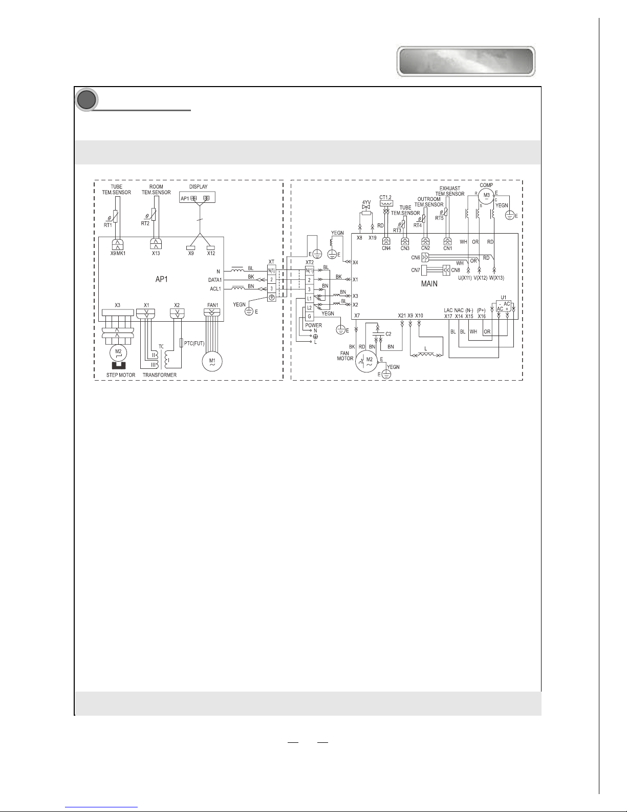
5
Circuit Diagram
These circuit diagrams are subject to change without notice. Please refer to the ones stuck on the machines.
SOLEUSAIR
KFHHP-12
12
66
66
6
Function manual and operation method of remote controller
Function manual of remote controller
This function manual is applicableto D.C. Variable Frequency
6.1.1 Temperature parameters
ƹ Room set temperature (T
set
)
ƹ Room ambient temperature (T
amb
)
6.1.2 Fundamental functions
After powered on, no matter when the compressor is started, the time interval between two startups
cannot be less than 3 minutes.
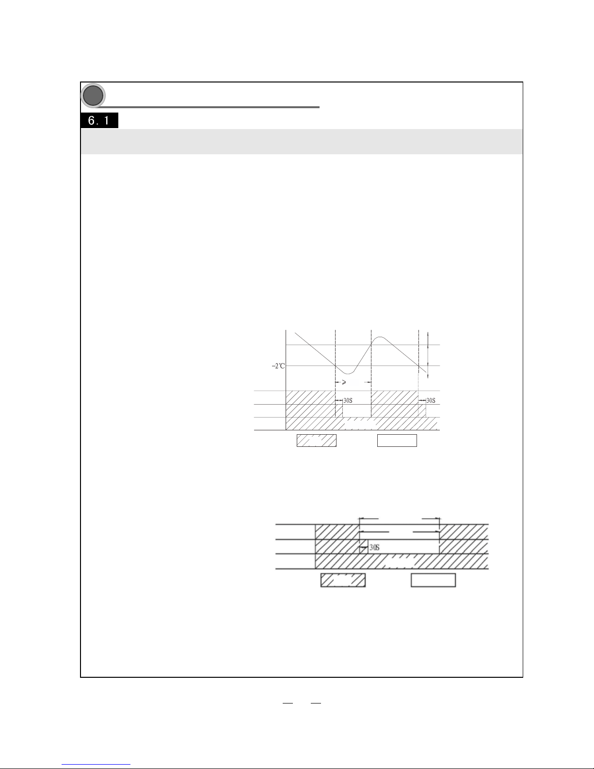
6.1.2.1 COOL mode
6.1.2.1.1 The condition and process of cooling
If T
ambTset
, COOL mode will act, the compressor and outdoor fan will run, and the indoor fan will run at the set
speed.
If T
ambTset
-2 , ć the compressor will stop, the outdoor fan will delay 30 seconds to stop, and the indoor fan will
run at the set speed.
If T
set
-2ć˘T
amb˘Tset
, the unit will keep running in the previous mode.
In this mode, the reversal valve will not be powered on and the temperature setting range is 16ć~30 .ć
6.1.2.2.1 The condition and process of drying
Tamd
Tset
Tset
3min
Compressor
Outdoor fan
Indoor fan
Start cooling
Original running state
Stop cooling
Set fan speed
Run
Stop
6.1.2.1.2 Protection function
ƹ Antifreezing protection
Under cooling and drying mode, after the compressor run about 10mins,when the pipe temp.of the
evaporator is to low, the compressor will stop, the outdoor fan will stop after 30s, under cooling
mode the indoor fan and swing motor will keep running in the original mode , under drying mode the
indoor fan will run at low fan speed, the swing motor will run in the original mode. When antifreezing
6.1.2.2 DRY mode
protection is eliminated and the compressor has stopped for 3 minutes, the unit will resume running in
the original mode.
Theperiod of antifreezingprotection
Compressor
Outdoor fan
Indoor fan
ı3 min
Run
Stop
ƹ Overcurrent protection
If total current is high, the compressor will run in limited or dropped frequency. When total current goes on
rising over the stated value, the compressor will stop, the outdoor fan will delay 30 seconds to stop.
The unit will adjust the running frequency of the compressor automatically according to the change of ambient
temperature.
15
 Loading...