

Page 1
Introduction and features
Technical Service Manual
for 13SEER DC INVERTER 24K
SOLEUSAIR
Model
KFHHP-22
Remarks
Page 2
/
3
62/60/58
2
3
Specifications and technical parameters
2
Model
Function
Rated Voltage
Total Capacit y ( W)
Rated Input ( W)
Rated Cur r ent (A)
Air Flow Volume (m
Dehumidifying Volume (l/h)
Model of Indoor Unit
Fan Motor Speed (r /min)
Output of Fan Mot or ( w)
Input of Heater (w)
Fan Motor Capacitor (uF)
Fan Motor RLA(A)
Fan Type-Piece
Diameter-Length (in)
Evaporator
Indoor
Unit
Pipe Diameter( in)
Row-Fin Gap(in)
Coil lengthxheightxcoil widt h(in)
Swing Mot or Model
Output of Swing Motor ( W)
Fuse (A)
Sound Pr essure Lev el dB ( A)
Sound Power Level dB ( A)
Dimension ( in)
Dimension of P ac k age(in)
Net Weight/Gr oss Weight(lb)
/h) (H/M / L)**
KFHHP-22
COOLING HEA TING
208-230V~
23800/22000B tu 27000/24200B tu
2240 2280
10.18 10.36
1050/950/880
3
KFHHP-22-ID
1400/1300/1200
20
0.4
Cross f low fan – 1
φ4.17 X35.04
Aluminum fin-c opper tube
Φ0.28
2-0.055
35.5X0.083X15
MP24GA
PCB 3.15A Tr ansfor mer 0. 2A
52/50/48
46.38 X12.83X8.94
49.8X16.42X13.11
38.6/53
Page 3
Outdoor
unit
Model of Outdoor Unit
Compressor Model
Compre ssor Type
L.R.A. ( A)
Compre ssor RLA( A)
Compressor Power Input( W)
Overload Prot ec tor
Thr ottling Method
St ar ting Method
Wor k ing Temp Range (ć)
Condenser
Pipe Diameter(in)
Rows-Fin Gap(in )
Coil lengthxheightxcoil widt h(in)
Fan Motor Speed ( r pm)
Output of Fan Motor (W)
Fan Motor RLA(A)
Fan Motor Capacitor (uF)
Air F low Volume of Outdoor Unit
Fan Type-Piec e
FanDiameter (in)
Defr osting Method
Climate Type
Isolation
Moisture Pr otect ion
P er missible E xc essive
Oper ating Pressure for the
Discharge Side(MPa)
P er missible E xc essive
Oper ating Pressure for the
Suction Side(MPa)
Sound Pr essure Lev el dB ( A)
Dimension (W/D/H)( in) 37.4X16.22X33.07
Package Dimension(W/D/H)(in)
Net Weight /Gross Weight (lb)
Refrigerant Charge (oz)
KFHHP-22-OD
C-6RZ146H1A
Rotary
40
8.4
1640
1NT11L-3979
Capillary t hr ottling
Tr ansducer star ting
-10~43
˄
Aluminum fin- c opper tube
26.9X32X1.73
Axial fan –1
Auto defrost
43.3X17.7X35.6
141.1/152.1
R410a/84
ć˅
φ0.3748
2-0.055
780/600
60
0.25
3
/
φ18.11
T1
I
IP24
4
/
59/58
Connection
Pipe
Length(ft)
Outer
Diameter
Max
Distance Length(ft)
Liquid Pipe (mm)
Gas Pi pe (mm)
Height ( ft)
26.25
Φ9.52(3/8”)
Φ16(5/8”)
40
100
The data above is subject to change without notice .Please refer to the nameplate of the unit
Page 4
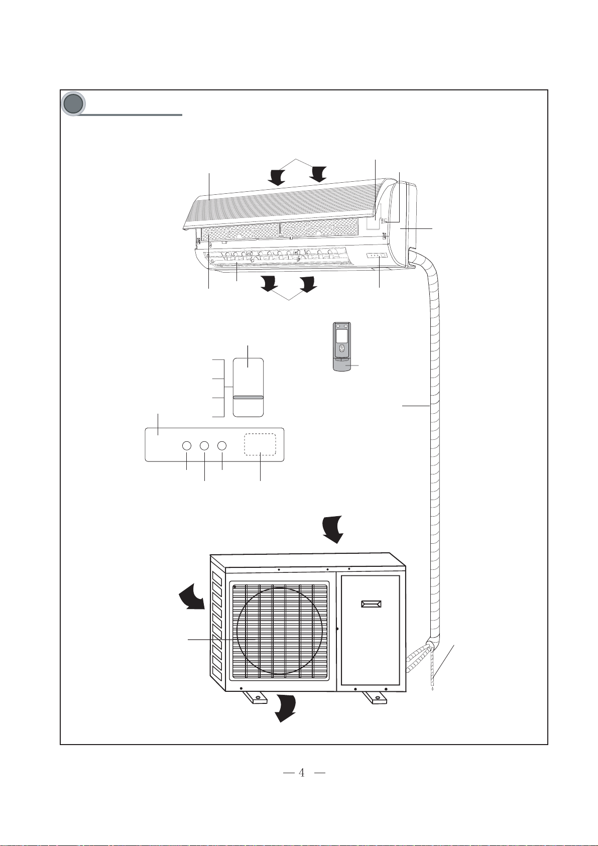
Components name
front panel
filter
air guider
dispaly board
front case
cover of electrical box
remote control
display
heating
cooling
run
receiver
connecting pipe and calbe
air outlet grill
drain hose
manual switch
manual switch
Outdoor unit
Indoor unit
Page 5
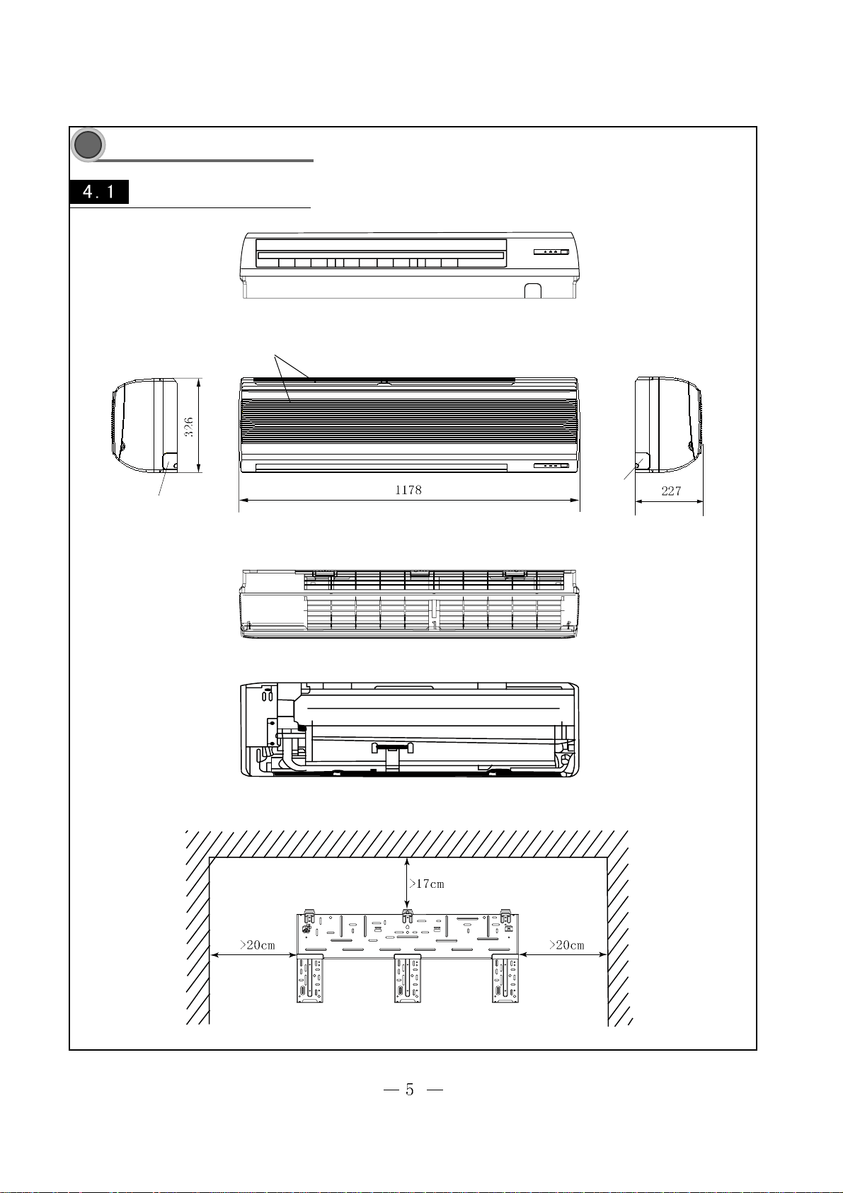
Overall and installation dimension
4
Overall and installation dimension of indoor unit
air inlet grill
left tube-exit sign
top view
KFHHP-22-ID
right tube-exit sign
left
rear view
Unit:mm
Ceiling
right
Page 6
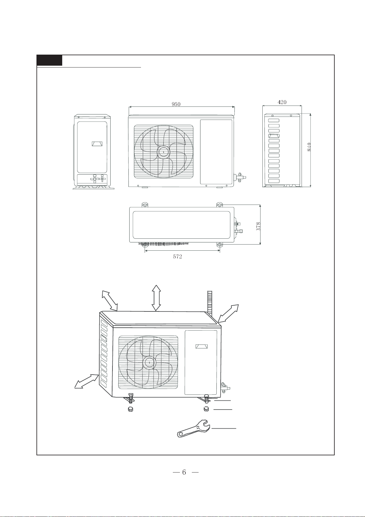
Overall and installation dimension of outdoor unit KFHHP-22-OD
over
over
over
bolt
nut
wrench
unit :mm
Ggggg
Page 7
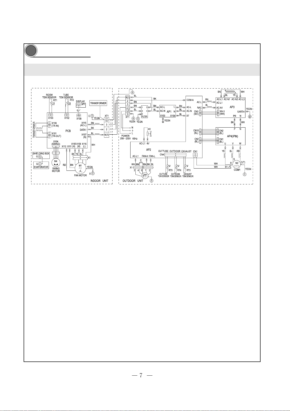
Electrical diagram
55
5
55
KFHHP-22
The diagram above is subject to change without notice.Please refer to the diagram label on the unit
Page 8
Function manual and operating method of controller
6.1 Function manual
6.1.1 Temperature parameters
ƹ
Room set temperatures(Tset)
ƹ Room ambient temperatures(Tin-amb)
6.1.2 Fundamental function
6.1.2.1 Cooling mode
ƽtemperature setting range is 16-30¨C
ƽunder this mode, fan motor of indoor unit operates at setting speed.
ƽwhen compressor stops because of malfunction protection, fan motor of indoor unit still operates at setting speed.
6.1.2.2 Dehumidifying mode
ƽTemperature setting range is 16-30`C
ƽIndoor fan motor runs at low setting speed.
ƽwhen compressor stops because of malfunction protection, indoor motor still operates at low speed.
6.1.2.3 Fan mode
ƽTemperature setting range is 16-30`C
ƽIndoor fan can operates at selected speed of HIGH,MED,LOW and AUTO.
6.1.2.4 Heating mode
ƽTemperature setting range is 16-30`C
ƽsending out remaining heat: after indoor fan runs at setting speed for 60s
ƽanti cold air: indoor fan will start in 2 minutes at latest
ƽwhen compressor stops at setting temp., indoor fan motor operates in discharging remaining heat
ƽwhen compressor stops because of malfunction protection, indoor fan runs in discharging remaining heat.
ƽon receiving signal of defrosting, indoor fan motor stops; when defrosting ends, fan motor runs under anti cold air status.
6.1.2.5 Auto mode
In this mode, indoor fan will run in Cooling, heating, air discharging mode according to the change of ambient temperature. And the protection
function is the same as under Cooling, Heating mode.
6.1.3 Other control
6.1.3.1 auto control of speed of indoor fan
indoor fan runs automatically at HIGH,MED,LOW speed according to the change of ambient temperature. The interval of speed switching is 3
minutes and 30 seconds at least. When in dehumidifying mode, fan runs at setting low speed.
6.1.3.2
when the power is on, the air guide louver will turns to A position counter-clockwise and closes the air outlet went.; after the unit starts in heating
mode, it turns to the max air outlet position D2; after unit starts in cooling mode, it will turns to D1 position and then back to L1 position; when in swinging
state, it will swing between L1 and D1 in cooling; between L and D2 in heating. After the unit is off, it will turns back to A position to close the air outlet
vent.
6.1.3.3 Timer control
The auto-start timer function can be set when the unit is off. When it reaches the time, the controller will function in the originally set mode. The
interval is 0.5 hour and the range of timer is 0.5-24 hours.
The auto-stop timer can be set when the unit is on. When it reaches the time, unit will be off automatically. The interval is 0.5 hours and range of
timer is 0.5-24 hours.
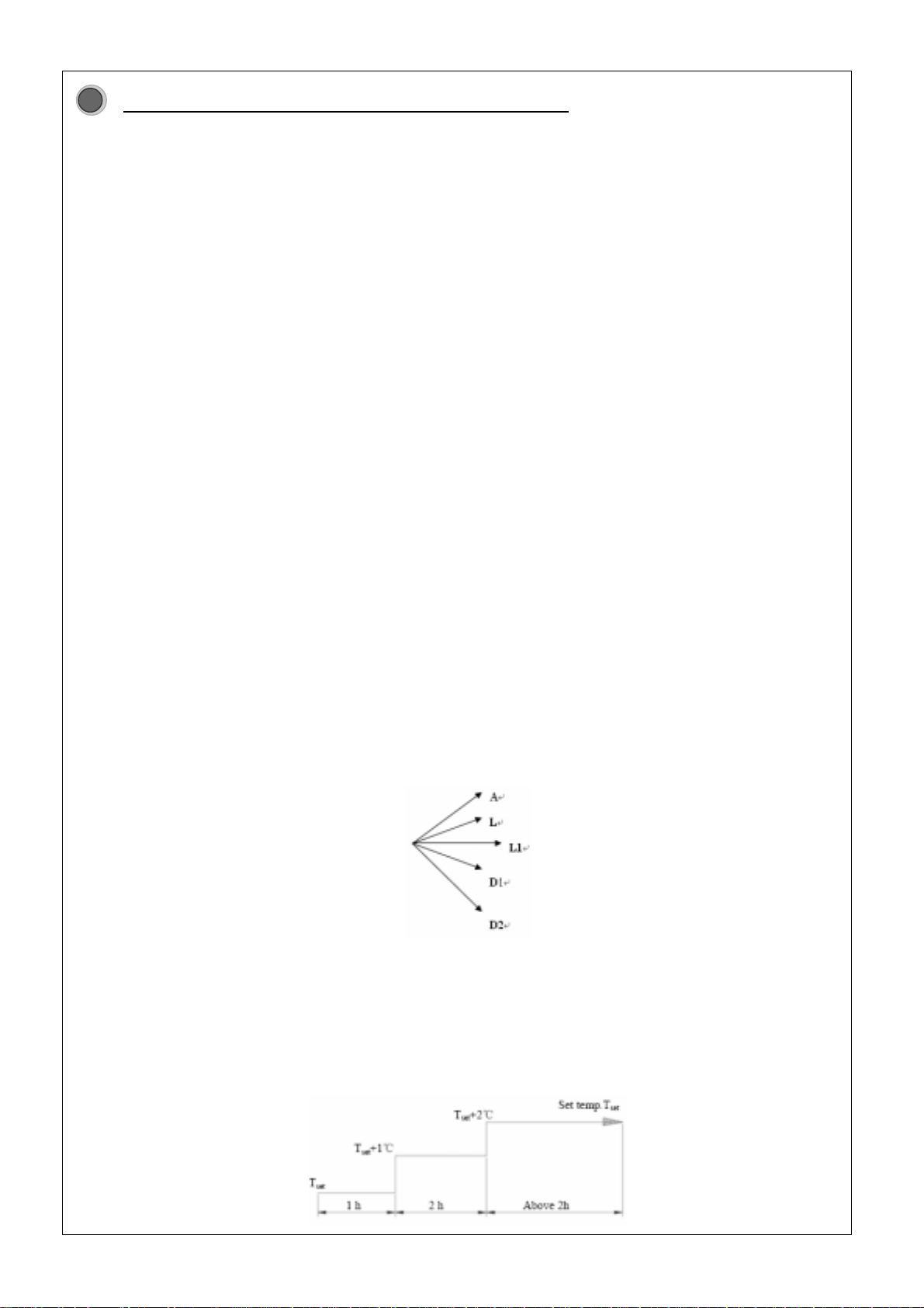
6.1.3.4 Sleep control
When units in cool or dry mode, after sleep mode has been set properly, the preset Tset will be increased by 1ć after sleep program has run for 1
hour. And Tset will be increased by another 1ć after 2 hours.Tset has been increased by 2ć totally in two hours. Then the unit will run at this set
temperature and at the set speed.
66
66
6
-8-
Page 9
When unit is in HEAT mode, after sleep mode has been set properly, the preset Tset will be increased by 1ć after the sleep program has run for 1
hour, and Tset will be decreased by another 1ć after 2 hours.Tset has been increased by 2ć totally in two hours Then the unit will run at this
temperature and at the set speed.
In Auto OR fan mode, the setting temp. will not change.
6.1.3.5 Toggle switch
1, If memory function is on, when unit is power-on and start operation and toggle switch is in STOP position, the unit will operates with STOP position; or
else unit starts under power-off memory. There is memory function with AUTO,RUN,STOP position. TEST position is without memory function.
2, If there is no memory function, unit will operate under previous switch position.
ƾ When toggle switch is on AUTO, unit operates in AUTO mode, and air swing on; if there is signal of remote control, then unit operates according to
signal.
ƾ When toggle switch is on TEST, indoor fan runs in high speed, and air swing on; indoor unit sends out signal of Cool mode on 16ć and 30ć
ambient temperature to outdoor unit. If malfunction of indoor or outdoor temp. sensor is detected, buzzer will give out beep to alarm. If there is signal of
remote control, unit operates as per remote control and indoor unit sends remote control signal to outdoor unit.
6.1.3.6 Communication failure
Communication failures happen if there is no correct signal received for 3 minutes
6.1.3.7 Buzzer control
When unit is power on or receiving remote control signal or the toggle switch is pressed, the buzzer will give out a beep.
6.1.3.8 Power-off memory function
1) contents of memory: mode(AUTO, COOL, DEHUMIDIFYING, HEATING, etc), setting fan speed, setting temperature, Timing etc.
2) if unit was on when power off, 3 minutes is delayed for indoor unit to send signal of starting to outdoor unit.
3) When power is on again, unit will operate in previous mode before power-off.
4) If there was no timer function in the last remote control dictation, then unit will memorize the last remote control dictation and operate according to
the previous mode
5) If there was timer function in the last remote control dictation and system was power-off before the time set, unit will memorize the last timer function
and it will time from the begin of restarting.
6) If there was timer function in the last remote control dictation and system was power-off at the time set, unit will operate in the mode before
power-off but timer won’t be on.
6.1.3.9 Failure detect of indoor temp. sensor
When unit is defrosting, temp sensor malfunction is not under detection. In other status temp sensor malfunction of indoor ambient and tube are
under malfunction. If the temperature is not between the minimum and maximum for continuous 30s, signal of error will be sent out.
When indoor temp sensor failures, it will send signal of closing down unit to outdoor unit.
6.1.3.10 Method for testing (min, med, nominal, max cooling or heating)
Temp. set in remote control 16 17 18 19
In Cool mode, press Sleep button 4
times in succession within 3
seconds
Temp. set in remote control 27 28 29 30
In Heat mode, press Sleep button 4
times in succession within 3
seconds
Press any button to exit.
Cooling mode: temperature signal sent to outdoor unit is compulsively set 16ć when cooling capacity is min, med, nominal or max.
Heating mode: temperature signal sent to outdoor unit is compulsively set 30ć when heating capacity is min, med, nominal or max.
Notice: when test is started, relevant indicating lamp blinks quickly. If there is malfunction, it will be displayed directly
Min. cooling Med. Cooling Nominal cooling Max. cooling
Min. heating Med. heating Nominal heating Max. heating
-9-
Page 10
Controller function of outdoor unit
6.1.1 Parameters of temperature
Exhausting gas temperature of outdoor unit(Tex)
Ambient temperature of outdoor unit(Tam)
6.1.2 Fundermental function of system
In wichever mode, once compressor start-up, it can only be close down 6 minutes later at
least(not including malfunction protection/mode switch which requires compressor to stop);Once
compressor closes down, it can only restart 3 minutes later at least(including mode switch, stop by
remote control etc.);compressor starts up after outdoor motor runs for 5 seconds
6.1.2.1 Cool mode
6.1.2.1.1
Working conditions and process of cooling
ƽwhen compressor in closing down state and (Tin-am-Tset)ı0.5ć,if unit start in cooling mode,
then cooling mode operates; outdoor fan motor and compressor start to run. The frequency of
compressor can be adjusted automatically according to need of cooling power by micro-computer.
ƽ during cooling process, when 0 ćİ(Tset-Tin-am) İ 2 ć ,the compressor operates in low
frequency.
ƽduring cooling process, when 0 need of cooling power and (Tset-Tin-am)˚2ć, then compressor
stops running. And outdoor fan motor stops in 60s.
NJIn this mode, there is no power supply for reversing valve. Range of temperature setting is 16-30
ć.
6.1.2.1.2 Frost-proof protection
In cool and dehumidifying mode, when frost-proof protection is detected, the compressor will run in
lower frequency or stops. And outdoor fan motor stops in 60s. When frost-proof protection ends,
Compressor resumes running.
6.1.2.1.3 Controlling principles of outdoor fan motor
If Tout-amı26ć, the fan motor runs in high speed.
If Tout-amİ24ć, the fan motor runs in low speed.
If 24ć˘Tout-amb˘26ć, the fan motor runs in original speed.
After fan motor runs in compulsive high speed for 3 minutes in starting-up, then the speed will be
controlled by the set principles
6.1.2.2 Dehumidifying mode
ƽWorking conditions and process of dehumidifying: the same with the ones in cooling mode
ƽstatus of 4-way valve: closed
ƽrange of temperature setting: 16-30 ć
ƽprotection function: the same with the ones in cooling mode.
6.1.2.3 Fan mode
ƽcompressor, outdoor fan motor and 4-way valve are closed and stopped.
ƽrange of temperature setting: 16-30 ć
6.1.2.4 Heating mode
6.1.2.4.1 Working conditions and process of heating
ƽwhen compressor in closing down state and (Tin-amb-3) ćİ(Tset-0.5) ć, if unit start in heating
mode, then heating mode operates. Outdoor fan motor ,compressor and 4-way valve start to run.
The frequency of compressor can be adjusted automatically according to need of heating power by
micro-computer.
-10-
Page 11

ƽ during heating process, when Tset ćİ(Tin-amb-3) ćİ(Tset +2)ć,the compressor operates
in low frequency.
during heating process, when (Tin-amb-3) ć˚(Tset +2)ć, then compressor stops running. And
outdoor fan motor stops in 60s.
Notice: It will take 2 minutes to power-off in 4-way valve when the unit closes down in heating mode
or switch from heating mode to other modes.
NJIn this mode, there is power supply for reversing valve. Range of temperature setting is 16-30ć.
6.1.2.4.2 Controlling principles of outdoor fan motor
If
Tout-ambİ19ć, the fan motor runs in high speed.
If Tout-ambı21ć, the fan motor runs in low speed.
If 19ć˘Tout-amb˘21ć, the fan motor runs in original speed.
After fan motor runs in compulsive high speed for 3 minutes in starting-up, then the speed will be
controlled by the set principles
6.1.2.4.3 Defrosting process
When defrosting conditions is detected, if compressor run in high frequency, then frequency will
be demultiplied first. Later compressor stops running and indoor fan motor stops. Outdoor fan motor
stops in 50s later. 4-way valve will be power-off in 45s. The defrosting functions operates when
compressor restart in 55s and frequency reaches 90hz. When the defrosting is over, the frequency
will drop until it reaches 60hz. 50s later 4-way valve and outdoor fan motor will be power-on.Then
frequency of compressor will rise to the required. But indoor fan motor have to start 2 minutes later
at least.
If compressor closes down for malfunction in heating mode, indoor motor will only exhausting
remaining heat.
6.1.3 Universal protection function of cool, heating, dehumidifying and auto
mode
6.1.3.1 Overloading protection function
When over-high temperature of tube (Ttube) is detected, frequency of compressor will be
demultiplied or limited. When Ttube is beyond maximum, compressor stops until Ttube restrores to
normal value.
If there are 6 continuous times of over-high Ttube protection, compressor will stop and can not
restart by itself. It can only be restart by pressing “ON/OFF” button. In operation if operating time of
compressor is over 7 minutes, the number of times will be zero cleared.
6.1.3.2 Time-delay protection of compressor
Compressor will restart in 3 minutes after it closes down.
6.1.3.3 High exhausting gas temp. protection of compressor
When over-high temperature of gas exhausted (Tex) is detected, frequency of compressor will
be demultiplied or limited. When Tex is beyond maximum, compressor stops until Ttube restrores to
normal value.
If there are 6 continuous times of over-high Tex protection, compressor will stop and can not
restart by itself. It can only be restart by pressing “ON/OFF” button. In operation if operating time of
compressor is over 7 minutes, the number of times will be zero cleared.
6.1.3.4 Current protection function
(1) overcurrent protection
If current of whole unit is beyond max. limit, unit will close down as if indoor temperature reaches
the set temperature. Unit will restore automatically after compressor has been stop for 3 minutes.
-11-
Page 12

If there are 6 continuous times of protection, compressor will stop and can not restart by itself
and send signal of error to indoor unit. It can only be restart by pressing “ON/OFF” button. In
operation if operating time of compressor is over 7 minutes, the number of times will be zero
cleared.
(2) frequency demultiplying, limitation of current control
If current of whole unit is high, frequency of compressor will be demultiplied or limited. If normal
current value is detected, whole unit restore to operate normally.
6.1.3.5 Communication failure
When there is no right signal from indoor unit for continuous 3 minutes or no right signal from
driving slug within 60s, communication failure happens. Outdoor unit will closes down.
6.1.3.6 Module protection
Compressor will detect signal of module protection right away after it starts. Compressor closes
down in module protection status as if room temperature reaches the set value. And relevant error is
displayed. Compressor restores to run after stopping for 3 minutes.
If there are 6 continuous times of protection, compressor will stop and can not restart by itself. It
can only be restart by pressing “ON/OFF” button. In operation if operating time of compressor is
over 7 minutes, the number of times will be zero
6.1.3.7 overheating protection of module
When IPM temperature is too high, frequency of compressor will be demultiplied or limited. Wen
IPM temperature is beyond maximum, compressor closes down. The whole unit can only restart
when IPM temperature returns to norm and compressor has been stopping for 3 minutes.
If 3 times of IPM temperature protection happens in 1 hour, compressor will stop and can not
restart by itself. It can only be restart by pressing “ON/OFF” button.
6.1.3.8 overloading protection of compressor
When overloading switch of compressor operates, it will closes down as if room temperature
reaches set value. Whole unit can only restart when compressor has been stopping for 3 minutes
and overload switch resets.
6.1.3.9 PFC protection
When air conditioner starts in cooling, heating or dehumidifying mode, compressor starts and
frequency rises to 30hz. PFC protection is on after it runs for 30s.
Compressor closes down in whatever condition, PFC and compressor closes down at the same
time.
PFC protection signal will be detected once after PFC starts; when PFC protection is on, PFC and
compressor closes down at the same time.
PFC restores automatically 3 minutes later after failure happens
6.1.3.10 Testing of malfunction of temp. sensor and IPM overheating
(1) In stand-by status outdoor tube temperature sensor, ambient temperature sensor and sensing
device error of overheating IPM are not under detection.
(2) error of temp. sensor of exhausting gas and error of IPM overheating will be under detection after
the whole unit is on and compressor operates for continuous 3 minutes.
(3) within 10 minutes after compressor starts or within 10 minutes after defrosting or oil returning in
heating mode, error of outdoor tube temp. sensor are not under detection.
(4) when error of IPM overheating or failure of temp. sensor is detected, whole unit will closes down
immediately.
-12-
Page 13

6.1.3.11 The status of indicator in outdoor unit
Notice: When the unit is power-on again, the times of all the protection above (including: overloading protection, high
exhausting gas temp. protection of compressor, overcurrent protection, module protection etc.) will be reset.
D11 Meaning D12 Meaning D13 Meaning
blink 1 time compressor starts to run blink 1 time cooling overload
protection stop
blink 1 time quick cooling/heating
blink 2 tim es exhaust protection st op blink 2 tim es heating overload
protection stop
blink 2 times defrosting
blink 3 times closing down for NEC
driving module protection
blink 3 times communication failure
with indoor unit
blink 3 times oil returning
blink 4 times closing down for
overcurrent protecti on
blink 4 times communication failure with
NEC module
blink 4 times nominal
cooling/heating
blink 5 times closing down for
overloading protection
blink 5 times communication failure with
computer
blink 5 tim es max. cooling/heating
blink 6 tim es cooling antifreezing stop blink 6 times failulre of outdoor ambient
temp.sensor
blink 6 times medial cooling/heating
bli nk 7 times sensor m alfunc ti on st op blink 7 times failure of outdoor
tube-temp.sensor
blink 7 tim es min.cooling/heating
blink 8 times closing down for
communication
failure(including indoor
unit and NE C driving
module)
blink 8 times failure of outdoor
gas-discharge
temp.sensor
blink 8 tim es unit off
blink 12 times closing down for IPM
overheating protection
blink 9 times communication failure
sent from indoor
blink 9 tim es low pressure and can’t
resume
blink 10
times
wrong parameters sent to
NEC driver, unit closes
down
blink 11
times
IPM temp. sensor failure
D14 meaning D15 meaning D16 meaning
blink 1 tim e frequency demultiplying
for high t emp.of gas
discharged
blink 1 tim e frequency limiting for high
temp.of gas discharged
on Be receiving or sendi ng
computer data
blink 2 tim es frequency demultiplying
for overcur rent protection
blink 2 times frequency limiting of
overcurrent protecti on
off receiving or sending
computer data finished
blink 3 tim es frequency demultiplying
for cooling overload
blink 3 times frequency limiting for
cooling overloading
blink 4 tim es frequency demultiplying
for heating overload
blink 4 times frequency limiting for
heating overloading
blink 5 tim es frequency demultiplying
for frost-proof
blink 5 tim es frequency of current 9.4 A
lasting for 2 minutes
-13-
Page 14

D14 Mean ing D15 Meaning
blink 6 times Unit closing down for
min.frequency
blink 6 tim es frequency of current 12 A lasting for 2 minutes
blink 7 times Unit closing down for
PFC protection
blink 7 tim es frequency limiting or demultiplying for rate of
frequency variation out of control
blink 8 times Unit closing down for
compressor overloading
blink 8 tim es frequency limiting or demultiplying of compressor
current
blink 9 tim es frequency limiting or demultiplying for over temp.of
IPM module
D17 Mean ing D18 Meaning
blink 1 tim e too low DC input voltage On receiving or sending indoor d ata
blink 2 tim es too high DC voltage
when no short-circuit in
computer monitor port
off receiving or sending indoor data finished
blink 3 tim es AC current protection blink normal communication between main borad and
driving board
blink 4 times IPM abnormality
short-circuit in
computer monitor port
not
blink
abnormal c ommunication between m ain board and
driving board
blink 5 times reserved built-in PFC
protection
blink 6 times start-up failure
bli nk 7 times phase-losi ng or ou t of
control
blink 8 times first PFC protection ;then
module protection
-14-
Page 15

Disassembly procedures
77
7
77
Disassembly procedures for indoor unit
Procedures and pictures
Disassembly front panel
(Refer to figure 7-1)
Disassemble filter
Push filter inside and pull it upward.Take the filter away
(Refer to 7-2)
Disassemble guide louver
filter
front panel
electrical box top cover
hook
screw
Bend the guide louver with strength and let out the hook
(Refer to figure 7-3)
-15-
hook
guide louver
Page 16

Disassemble electrical box
Disassemble electrical box cover
Disassemble front case
Unclench 3 screw covers;then unscrew 6 screws and lift
it backward.
(Refer to figure 7-4)
screws
screws
hook
electrical box cover
display board
Unscrew the srew fixing the display board and take the
board off.Hold the cover and press it to loosen the hook.
lift it upward and remove the box cover
(Refer to figure 7-5)
grounding nut
tube sensor
ambient sensor
disassemble the grounding nut on evaporator;take away tube sensor
unplug the connecting terminal for indoor fan motor and stepping motor
Unscrew the screw fixing electrical box.Take out it.
(Refer to figure 7-6)
-16-
Page 17

Disassemble water tray
Unloose the clasp fixing water tray;lift and disassemble it
(Refer to figure 7-7)
Disassemble evaporator assy
Unscrew 2 screws on the clamp and remove the clamp
unscew the 2 screws fixing evaporator on left and right side.
Take out the evaporator by you hand and push it backward to let out
the side clasps from the groove.Take out the evaporator carefully
,-,protect the connecting pipe
(Refer to figure 7-8,7-9,7-10)
water tray
hook
screws
clasp
screws
clamp
-17-
Page 18

Disassemble cross flow fan
Disassemble motor
take out the bearing on the left and remove the cross flow fan
fan bearing
cross flow fan
screws
screws
motor
press plate
Unscrew the screws fixing press plate and take out press plate
Unscrew the one M4 screws and remove the motor
(Refer to 7-11)
(Refer to 7-12)
-18-
Page 19

Disassembly procedures for outdoor unit
Operating procedures /pictures
Disassemble front side plate
unsrew the 4 srews around the front side plate and take off it
(Refer to figure 7-13)
Disassemble top cover
Unsrew the srews around the top voer plate;lift the
top cover and remove it
(Refer to figure 7-14)
front side plate
srews
top cover
srews
Disassemble rear grill
Unscrew the 4-self tapping screws on rear side plate
and take off the grill.
-19-
srews
rear grill
Page 20

Disassemble right side plate
Disassemble electrical box
Disassemble housing case
unsrew the screws around the housing case and take off it
housing case
screws
screws
cover of electrical box
screws
screws
right side plate
unscrew the 7 srews in right side plate,condensor side plate and
valve support;lift right side plate and remove it.
(Refer to 7-19)
Screw out the 2 screws fixing the electrical box;
lift it and remove it.
(Refer to figure 7-17,7-18)
-20-
Page 21

Operating procedures /pictures
Disassemble axial-flow fan
Loosen the nut with spanner and remove it.
axial-flow fan
Disassemble motor and motor support
Unscrew four tapping screws fixing the motor,and
remove the motor.Unscrew the two tapping screws fixing
the motor support,lift and remove it.
(Refer to figure 7-21)
motor support
nut
motor
screws
cable
screws
Disassemble 4-way valve
Unscrew the nut holding 4-way coil and remove the coil;
Use wet cotton cloth to wrap 4-way valve;unsodler 4 points
connecting 4-way valve and remove it.
Be quick during the process;try to make the cotton
wet all the time.Don't allow the flame to burn the
lead-out calbe of compressor
Refer to figure 7-22)
4-way valve
soldering points
-21-
Page 22

Disassemble compressor
Unsolder the soldering points between the pipes and compressor;unscrew
the three nuts with washers at the foot of compressor;take out the compressor
compressor
(Refer to figure 7-25)
Figure
compressor nuts
Disassemble valves
Unsrew the two screws fixing the big valve;unsoldering the soldering
points between the big valve and air-return duct;remove big valve
(When unsoldering,use wet cloth to wrap the big valve completely
to prevent it from being harmed by high temperature.
Unscrew the 2 screws fixing small valve;unsolder the joint points
between small valve and fork type pipe;remove small valve
(Refer to figure 7-24)
small valve
screws
big valve
Disassemblle capillary
Unsolder the joint points between capillary and other pipelines;them it
can be removed
(Refer to figure 7-23)
capillary
Operating procedures/pictures
-22-
Page 23

Exploded view and components&part list
8
indoor unit
KFHHP-22-ID
-23-
Page 24

Components and part list of indoor unit
Part Code
QtyNo Description
KFHHP-22-ID
1 Wall- Mounting Fr ame 01252398 1
2 Rear Case 22202040 1
3 Water T r ay 20182043 1
4 Rear G r ill 01473007 1
5 Upper Air Deflect or 10512062 1
6 Lower G uide Louver 10512063 1
7 Scr ew Cap 242520053 3
8 Air Louver 10512030 15
9 Swing Lever 10582040 3
10 Drain Pipe 05232411 1
11 Cross Flow F an 10352420 1
O-Gasket of Cross Fan
12
Bearing
13 Ev apor ator Assy 010041291 1
14 Ev apor ator Lef t Support 24212041 1
15 Front Case Sub-Assy 20002572 1
16 Filter S ub- Assy 11122051 2
17 Remote Control 30510029 1
18 Front P anel 20002375 1
19 Receiv er B oar d 30046093 1
Ambient Temperat ur e
20
Sensor˄15K
21 Wire Clamp 71010103 1
22 Terminal Board 42011233 1
23 Toggle Swit c h 10582007 1
24 Electr ic B ox Cover 201022521 1
25 Electr ic B ox Cover 201022512 1
26 Main P CB M9WA25A 30039161 1
27 Fuse T3.15AL 250V 46010014 1
28 Transformer 41X26. 5F 43110025 1
29 Electr ic B ox 201022501 1
30 Tube Sensor˄20K
31 Sensor Insert 42020063 1
Lower Shield Cover for
32
Electric B ox
33 Fixed Clip 02112009 1
34 Motor F ixed Clip 26112069 1
35 Fan Motor FN30C 150121071 1
Retaining P late of
36
Evaporator
37 Sheet Met al P iec e 02123005 1
38 Stepping Mot or MP24GA 15212102 1
Upper Shield Cover for
39
Electric B ox
40 Pipe Clamp 26112071 1
˅
˅
76512203 1
390000451 1
390000591 1
01592048 1
24212042 1
01592033 1
-24-
Page 25

Exploded view of outdoor unit
KFHHP-22-OD
-25-
Page 26

Components and part list of outdoor unit
Part Code
KFHHP-22-OD
1 Fr ont Gr ill 01473001 1
2 Housing 01433011 1
3 Small Handle 26235401 1
4 Clapboard Assy 01233039 1
5 Axial Flow Fan 10335253 1
6 Fan Motor F W60H 15013704 1
7 Motor S uppor t Sub-Assy 01703087 1
8 Condenser A ssy 01103813 1
9 Temp Sensor Support 24213005 1
10 Top Cover 01255262 1
11 Rear Grill 01475252 1
12 Reactor 43120011 1
13 Electr ic B ox Assy 01403591 1
14 Module S uppor t 24213008 1
15 PCB JG P 011 30111018 1
16 Electr ic B ox Cover S ub- Assy 01403629 1
17 Main P CB 2 W9W2 30039165 1
18 PCB Support˄up
19 PCB Support˄down
20 PCB Support 24213009 1
21 Main P CB 1 W9W2 30039164 1
22 Filter ing B oar d W9W2 30039163 1
23 Temperature S ensor 3900028001 1
24 Sensor Insert 42020063 1
25 Sensor Insert 42020066 1
26 Capacitor 33010027 1
27 Terminal Board 42010255 1
28 Filter 43130008 1
29 Wire Clamp 71010102 1
30 Isolation Washer 70410523 1
31 Wire Clamp 71010003 1
32 Cable-Cross Loop 76514004 5
33 Radiator 49013011 1
34 Capillary S ub- Assy 03103391 1
35 Cut-of f Valve 07130209 1
36 4-way Valve 43000411 1
37 4-way Valve Fittings 4300040022 1
38 Gas Valve Sub-Assy 07103030 1
39 Rear Side Plat e S ub- Assy 01302005 1
40 Compress or 00103501 1
41 Underpan A ssy 01203560 1
42 Front S ide P late 01302007 1
43 Choke Plug 06813401 1
˅
˅
26153031 8
24213010 8
QtyNo Description
-26-
Page 27

Troubleshooting
d
N
hei
r
y
p
9
Analysis in this section is used for D.C. Variable Frequency Series. Before analysis, you can diagnose
according to the code displayed on indoor unit or indicator display on outdoor unit. (Refer to Malfunction
display section).
Air
conditi
oner
cannot
start up
Breaker trippe
or fuse burnt out
Air conditioner
does not response
after powered on.
(The buzzer does
not sound after the
plug is connected
and the unit does
not response after
the remote
controller is used
to turn it on)
Remote
controller does
not receive signal
(When powered
on, the buzzer
will send out a
sound, unless it is
broken)
When the breaker is set ON, it will
trip at once
When the unit is turned on, the
breaker will trip in a few minutes
o power supply
The power plug is not or poorly
connected
Controller fuse is burnt out
Loose or poor contact of transformer
connection, or transformer malfunction
The controller is broken
Batteries of remote controller are low
Malfunction of remote controller
Loose or poor connection of receiving
head
Receiving head is broken
Measure t
for grounding to confirm whether
there is electrical leakage or short
circuit in the unit
Insulation malfunction of line or componen
in the air conditioner. Insulation breakdow
occurs after radiation, which causes shor
circuit or electricity leakage. Measure
insulating resistance or use one-by-on
elimination method;
Malfunction of fuse. Replace it.
Check power supply circuit
Check and plug well plug, make
Change control fuse
Secure the wire connection: measure
the output voltage of the transformer
and replace it if the value is wrong
Replace the controlle
Change batter
First press the "AUTO" button of the
manual switch. If there is no response,
check according to the above method;
if it is normal after the button is
ressed, check if the installation
location and wire connection of the
receiving head are correct. If correct,
replace the receiving head, or the
remote controller.
nsulating resistance
-27-
Page 28

When unit is
cooling or
heating, both
compressor and
outdoor fan don'
t
run
When unit is
cooling or
heating, the
compressor runs
b
ut outdoor fan
doesn't run
When cooling or
heating, outdoor
fan runs, but
compressor
doesn't run.
When cooling or
heating, outdoor
fan runs, but
compressor
doesn't run.
Fan doesn't run
when FAN mode
is set
Abnormal power supply of outdoor unit
Damage of outdoor main control board
Breakage of outdoor power module
Improper setting of temperature
Breakage of outdoor fan motor
Wrong wire connection
Breakage of outdoor main control board
Breakage of outdoor fan capacitor
Malfunction of compressor
Poor contact of connection between the
main control board and module
Abnormal input of power module
Abnormal output of power module
Compressor temperature is too high
Wrong wiring
Damage of outdoor main control board
Check the circuit according to circuit diagram
Replace the main control board
Replace the power module
Adjust the set temperature
Replace the fan motor
Wire according to the circuit diagram
Replace the main control board
Replace the fan capacitor
Replace the compressor
Re-fasten the connection
Check if input is 320V. If not, replace the
rectifie
r
Replace the power module
Cool the compressor for 30 min before running
Wire according to the circuit diagram
Replace the outdoor main control board
Burn-out or broken wire of indoor fan
moto
r
Wrong wirin
g
Circuit break or damage of fan motor
Repair or change the fan motor
Wire according to the circuit diagram
Replace the indoor main control board
-28
Page 29

Improper setting of temperature
d
f
D
f
Repl
Adjust the set temperature
Poor cooling
(heating) effect
Whether cooling (heating) loa
Leakage or shortage of refrigerant
Leakage occurs between high and
low pressure inside compressor
Malfunction of
refrigerant flow
Malfunction of four-way valve
Partial blockage of capillary
Blockage of cooling system
Poor thermal insulation of connecting
Heat exchanger of outdoor unit
Check the estimated load of cooling (heating)
Vacuumize after leakage detection
and leakage repair. Charge refrigerant
according to specification.
Replace the compressor
Replace the four-way valve
Replace the capillary
Use the method of observing condensation
on the evaporator and pressure value o
high pressure manometer to see whether
the system is blocked and carry out
corresponding handling on the system
Ensure that both thick pipe and thin pipe are insulated
well. The exposed part of the connector and copper pipe
Clean the dust accumulated on the
Air filters are blocked
Air circulation
Fan speed is set too slow
is insufficient
Fan speed turns low
Improper installation location
Outdoor temperature is too high
Indoor sealability is inadequate; too many
people go in and out frequently; there is
heating unit in the room.
Clean the filter
Set the fan speed to high or medium
amage o
capacitor
damaged
Damage of
motor
Outdoor unit should be installed in a
place with well ventilation
Flashing or awning can be installed appropriately. If the
max. cooling capacity cannot be satisfied, replacement of
the air conditioner is recommended.
ace the
capacitor
Replace the motor
Maintain a certain degree of indoor sealability. Try not to
use appliance with high amount of heat.
29
Page 30

water leakage
drain hose is blocked or broken replace the drain hose
wrap and tight it again
adjust the location of fan
abnormal things in indoor unit
remove it
compresoor shakes overly
pipes in outdoor unit collides set the pipes apart
adjust the washer and tight the bolt
metal plates collides
tighten the connecting bolt
indoor fan collides with other parts
outdoor fan collides with case
adjust the fan location
abnormal sound inside compressor
replace compressor
abnormal electromagnetic sound in
short circuit inside electromagnetic valve;repalace it
4-way valve in HEAT mode
stick shake-reduction plaster between the metal plates
CAUTION:
1,When repairing,before the voltage between module PN is measured below 50V,do not touch any terminal
to avoid electrical shock
2,When replacing power module and rectifier,make sure to spread the indicating paste evenly
abnormal shake
or sound
-30-
connector of refrigerant pipe isn't wrapped well
Page 31

Malfunction display section
9.2
Analysis or handling of some malfunction display:
1, Compressor discharge protection:
Possible reasons: shortage of refrigerant; block of air filter; poor ventilation or air flow short pass
in condenser; system has noncondensing gas(ge. Water, air);blockage of capillary (including
filter); leakage inside 4-way valve causes incorrect operations; malfunction of compressor;
malfunction of protection delay; malfunction of gas discharge sensor; too high outdoor temperature.
Handling process: refer to the malfunction analysis in the above section
2, low voltage overcurrent protection:
Possible reasons: sudden drop of power supply or overloading
3, Communication malfunction:
Handling method: check if communication signal cable is connected reliably
4, temp sensor open or short circuit:
Handling method: check whether sensor is normal, connected with the corresponding position on
the controller and if damage of lead wire is found
5, compressor overload protection:
Possible reasons: insufficient or too much refrigerant; blockage of capillary and increase of
suction temp.; improper running of compressor, burning in or stuck of bearing, damage of discharge
valve; malfunction of protector.
Handling method: adjust refrigerant amount; replace the capillary; replace the compressor; use
universal meter to check if the contactor of compressor is fine when it is not overheat, if not replace
the contactor.
6, system malfunction:
i.e overload protection. When tube temperaturec (Checking the temperature of outdoor heat
exchanger when cooling and checking temperature of indoor heat exchanger when heating) is too
high, protection will be activated.
Possible reasons: outdoor temperature is too high when cooling; insuffient outdoor air circulation;
refrigerant flow malfunction.
7, IPM module protection:
Handing method: if module malfunctions and can not be restored for long time, please
disconnect power supply. And connect again after about 10 minutes later. If repeating this method
for several times and malfunction still exist, please replace the module.
8, PFC protection:
Possible reasons: outdoor temperature is too high; over-high temperature of PFC module; power
of whole unit is too high and current is too high; low vollage in PFC; bad contact between the cables
in PFC control board.
Handing method: If PFC protection happens, please check connecting cables of PFC board first.
If the whole unit can not operate normally and PFC protection happens all the time, please replace
PFC.
9, refrigerant charging:
Similar with the procedures of the over 5kw wall split models.
Notice: refrigerant charging can only be started after whole unit has been operating stably for about
10 minutes.
-31-
Page 32

7. Module protection :
Handling method:
Check if the voltage between power module P and N is too low and
if the current is too high. In normal condition, voltage between P and
N should be about 320V.
Normal
Abnormal
Check power supply circuit of outdoor unit (if PTC resistance
rectifying bridge, reactor, capacitance etc. is ok).
Temperature of power module is too high,
which causes overheating protection
Protection is still displayed
Confirm the setting status of outdoor unit (cooling)
Normal
Confirm if outdoor fan motor is running; unplug the
three connecting wires between U, V, W of compressor
and power module. Turn on the unit to see if outdoor
fan runs normally (about 1 minute)
Outdoor fan stops
Measure the voltage of outdoor
fan connector
No voltage
Normal voltage
Replace the fan
Replace the mainboard
motorof outdoor unit
Check if radiating paste is spread
evenly or radiating sticker is stuck
well; if screws of power module
is tightened
Reinstall power module and
re-spread radiating paste or
stick radiating sticker on the
radiator of power module.
Poor radiation, heat exchanger
is dirty
Remove obstructions
and clean
Outdoor fan runs
Confirm if there is voltage output and balance of
voltage between any two phases of U, V and W.
Yes
No
Whether module type
Replace the power module
is correct
Normal
Abnormal
Normal
Abnormal
Measure the three-phase
Replace the module
with correct type resistance of compressor
Replace the
Whether cylinder of
compressor is stuck
compressor
If the unit runs normally after connected
with the new compressor for trial run, the
cylinder of original compressor is stuck
32
 Loading...