

Soleus Air HCC-C09HP-A,HCC-C12HP-A,HCC-C15HP-A Installation And Operating Instructions Manual
PACKAGED TERMINAL
AIR CONDITIONERHEAT PUMP
Installation and Operating Instructions
Model No.:HCC-C09HP-A
HCC-C12HP-A
HCC-C15HP-A
4004987
V140
CONTENTS
… … …
UNIT FEATURES 2
INSTALLATION INSTRUCTION
WIRING 7
OPERATING INSTRUCTIONS 8
MAINTENANCE AND CLEANING 10
NORMAL OPERA TING SOUNDS AND CONDITION 12
DIAGNOSTIC CODES 12
TROUBLE SHOOTING 13
WARRANTY
… ………………………………………………………
… …………………………………………
… …………………………4
.....................
… ……………………
… …………………………………
………………………………………
………
………
.................................................
14
IMPORTANT NOTES:
IMPORTANT NOTE TO THE SERVICER
Read this manual and familiarize yourself with the specific
items which must be adhered to before attempting to
service this unit. The precautions listed in this Installation
Manual are intended as supplemental to existing
practices. However, if there is a direct conflict between
existing practices and the content of this
precautions listed here take precedence.
manual, the
RECOGNIZE THIS SYMBOL
AS A SAFETY PRECAUTION
Before using this manual, check the serial plate for proper
model identification.
The installation and servicing of this equipment must be
performed by qualified, experienced technicians only.
Due to policy of continual product improvement, the right is
reserved to change specifications and design without
notice.
IMPORT ANT NOTE TO THE OWNER
This manual is to be used by qualified, professionally trained
HVAC technicians only. The
any responsibility for property damage or personal injury for
improper service procedures or services performed by an
unqualified Person.
manufacturer does not assume
WARNING
THE MANUFACTURER WILL NOT BE RESPONSIBLE FOR ANY
INJURY OR PROPERTY, DAMAGE ARISING FROM IMPROPER
SERVICE OR SERVICE PROCEDURES. IF YOU INSTALL OR
PERFORM SERVICE ON THIS UNIT, YOU ASSUME
RESPONSIBILITY FOR ANY PERSONAL INJURY OR PROPERTY
DAMAGE WHICH MAY RESULT, MANY JURISDICTIONS
REQUIRE A LICENSE TO INSTALL OR SERVICE
AIR CONDITIONING EQUIPMENT.
HEATING AND
WARNING
HIGH VOLTAGE
DISCONNECT ALL POWER BEFORE SERVICING OR
INSTALLING THIS UNIT. MULTIPLE POWER SOURCES MAY
BE PRESENT, FAILURE TO DO SO MAY CAUSE PROPERTY
DAMAGE, PERSONAL INJURY OR DEATH.
- 1 -
UNIT FEATURES
This unit has many features which are different than those
found on conventional PTAC units. The servicer must be
familiar with these features in order to properly handle
the unit .
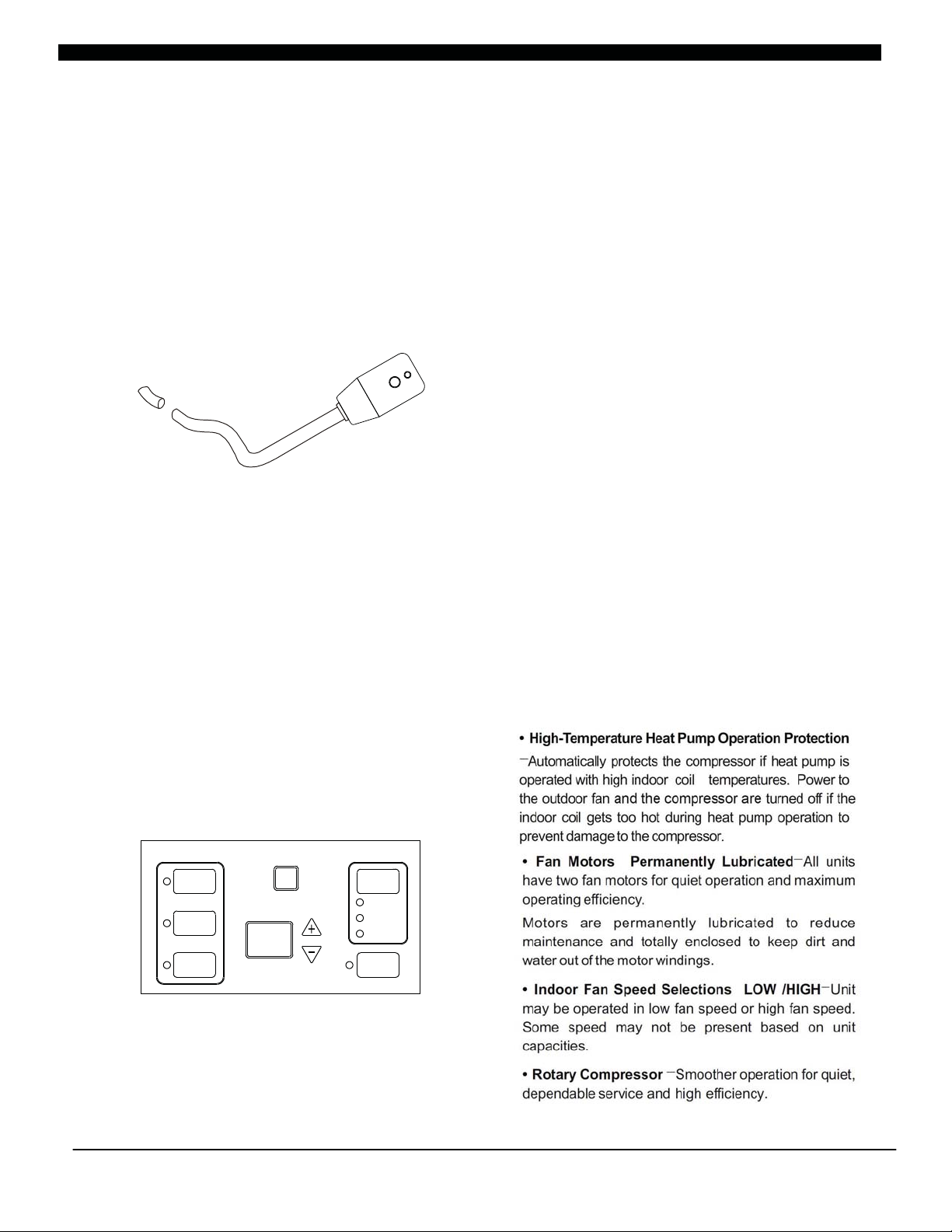
• LCDI Cords-Underwriters Laboratories and the
National Electric Code (NEC) now require power
cords that sense current
electrical circuit to the unit on units rated at 250 volts
or less. In the event that unit does not operate, check
the reset button located on or near the head of the
power cord as part of the normal troubleshooting
procedure.
LCDI power Cord
• Automatic 3-minute compressor lockout-After
the compressor cycles off, it will not restart for three
minutes.
• Random restart delay-To help eliminate power
surges after a power outage, the unit is equipped with
a two to four minute random restart delay feature.
Whenever the unit is plugged in with
switch turned on and the mode switch set in the cool
or heat mode, a random restart will occur. A random
restart condition can be avoided by setting the mode
switch in the fan only or off position before applying
power to the unit.
• Indication LEDs-The
correspond to fan operation and to indicate unit
status. The LEDs next to the selections ON/OFF,
FAN, COOL, and HEAT indicate which operational
leakage and can open the
the master
has LEDs that
-
• High Pressure Protection The unit will shut off
automatically when the pressure in the system is over
638 psi and within 10 minutes, after the compressor
turns off, the unit will restart when the pressure turns
back below 551 psi. This protection can effectively
avoid the burst and leakage of pipes, lessen the
system failures and prolong the service life.
-
• Failure Tolerance If the unit is in protection mode
less than 4 times in one hour, the accumulation times
will reset to avoid system failure. Only when the unit
enters protection mode more than 4 times in one
hour, the system will fail to restart automatically and
need manual restart.
Standard Physical Dimensions-The series PTAC
•
is with the same dimensions 42" wide x 16" high x 133/4" deep
Replacement of older units is made easy.
Weather-Protected Electrical Components-Vital
•
electrical components are protected from the weather
by locating them on the indoor
side of the weather
barrier.
Highly Featured Microprocessor Controls-
•
Microprocessor controls are programmed to interface
with the temperature sensors to maximize comfort
conditions for the room occupant and provide
outstanding features.
Thermistors are used to sense small changes in
temperature to give excellent room control and allow
the microprocessor to monitor and react to changing
conditions.
• Automatic Emergency Heat on Heat Pump
-Automatically uses electric resistance heat if
Units
the heat pump
selected room temperatur .
• High-Temperature Heat Pump Operation Protection
-Automatically protects the compressor if heat pump is
operated with high indoor
the outdoor fan turned off if the
indoor coil gets too hot during heat pump operation to
prevent damage to the compressor.
coil temperatures. Power to
HEAT
COOL
FAN
Figure 1
FAN
SPEED
HIGH
LOW
AUTO
ON/OFF
-2-
• Fan Motors Permanently Lubricated-All units
have two fan motors for quiet operation and maximum
operating efficiency.
Motors are permanently lubricated to reduce
maintenance and totally enclosed to keep dirt and
water out of the motor windings.
• Indoor Fan Speed Selections LOW /HIGH
may be operated in low fan speed or high fan speed.
Some speed may not be present based on unit
capacities.
• Rotary Compressor
dependable service and high efficiency.
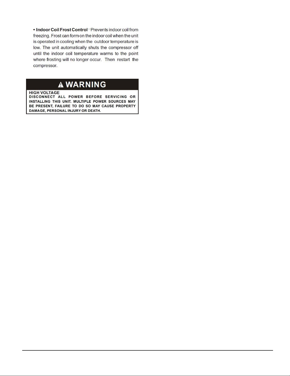
• Indoor Coil Frost Control
freezing. Frost can form on the indoor coil when the unit
is operated in cooling when the
low. The unit automatically shuts the compressor off
until the indoor coil temperature warms to the point
where frosting will no longer occur. Then
compressor.
-Smoother operation for quiet,
-Prevents indoor coil from
outdoor temperature is
-Unit
restart the
WARNING
HIGH VOLTAGE
DISCONNECT ALL POWER BEFORE SERVICING OR
INSTALLING THIS UNIT. MULTIPLE POWER SOURCES MAY
BE PRESENT, FAILURE TO DO SO MAY CAUSE PROPERTY
DAMAGE, PERSONAL INJURY OR DEATH.
UNIT ACCESSORIES
This unit is designed for through-the-wall installation in
new or existing buildings. To complete the installation
of this PTAC, an insulated wall sleeve and an outdoor
grille (either the stamped aluminum grille, or the
architectural grille ) are required.
The chassis
are shipped in one carton.
,cabinet front and wall mount thermostat wiring
(not included in this package).
OPTIONAL ACCESSORIES
Power switch Kit
Wall Sleeve Kit
Key Lock Kit
Drain Kit
Filter Kit
Hard Wire Kit
Wire Harness Kit
Architectural Grille Kit
Stamped Louver Kit
LCDI Power Cord
Wireless IR Antenna
Wireless IR Thermostat
Electric And
IR REMOTE CONTROLLER
NOTE: Consult sales literature for the appropriate
voltage and amperage selections, if applicable.
Non Electric Sub Base Kit
-3-
INSTALLATION INSTRUCTIONS
(
)
(
)
To ensure that the unit operates safely and efficiently, it must be installed, operated and maintained according
to these installation and operating instructions and all local codes and ordinances or, in their absence, with the
latest edition of the National Electric Code. The proper installation of this unit is described in
the following
sections. Following the steps in the order presented should ensure proper installation.
WARNING
HIGH VOLTAGE
DISCONNECT ALL POWER BEFORE SERVICING OR
INSTALLING THIS UNIT. MULTIPLE POWER SOURCES MAY
BE PRESENT, FAILURE TO DO SO MAY CAUSE PROPERTY
DAMAGE, PERSONAL INJURY OR DEATH.
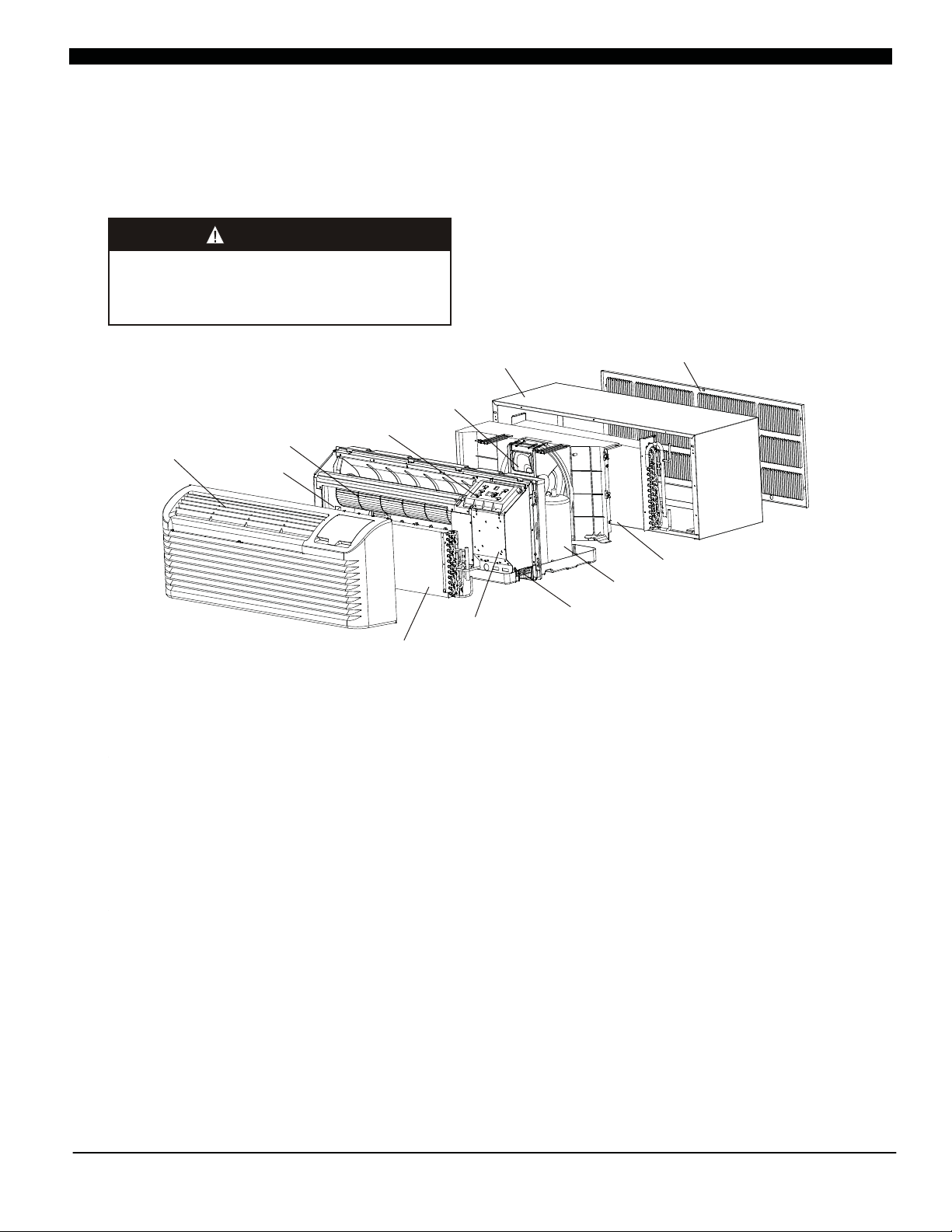
Outdoor Fan
Wall Sleeve
not included in the package
Wall sleeve
Outdoor Grille
not included in the package
Outdoor grille
Display Module
Outdoor coil
Rotary compressor
Power cord coverplate(not show)
Control box
Indoor coil
Front and discharge grille
Indoor Fan
Electric heater
Figure 2
WALL SLEEVE ASSEMBLY (OPTIONAL ACCESSORY)
Two kinds of wall sleeve are optional for customers, one is reassemble
welding integrated wall sleeve.
Removable Wall Sleeve
The removable wall sleeve can be removed and occupies less space and is convenient to transport. Follow the
below steps to install :
a) Unpack all parts and accessories, referring to Fig 1.
b) Assemble the wall
sleeve by first “clip locking” the side pieces to the bottom piece.
c) Assemble the top piece to the assembled side and top piece.
Welded integrated wall sleeve
Welded integrated wall sleeve is featured by artistic appearance and stable structure referring to Fig 2.
Customers can purchase together with unit.
wall sleeve and the other one is
4
2
"
K
C
O
L
P
I
L
C
S
P
Fig
EV
E
E
L
E
C
E
I
M
O
T
T
O
B
1
Fig 2
1
6
"
3
"
4
3
1
-4-
 Loading...