

Soleus Air HCC-C09HP-A, HCC-C12HP-A, HCC-C15HP-A Installation And Operating Instructions Manual
Page 1
PACKAGED TERMINAL
AIR CONDITIONER with HEAT PUMP
Installation and Operating Instructions
Model No.:HCC-C09HP-A
HCC-C12HP-A
HCC-C15HP-A
V140422
Page 2
CONTENTS
UNIT FEATURES 2
INSTALLATION INSTRUCTION
WIRING 7
MAINTENANCE AND CLEANING 10
NORMAL OPERATING SOUNDS AND CONDITION 12
DIAGNOSTIC CODES 12
TROUBLE SHOOTING 13
… …………………………………………
… …………………………4
… ………………………………………………………
… … …
… … … … …… … … …
………
… …………………………………
………………………………………
OPERATING INSTRUCTIONS 8… … …
-1-
RECOGNIZE THIS SYMBOL
AS A SAFETY PRECAUTION
WARNING
HIGH VOLTAGE
DI SCONNE CT AL L PO WER B E F O R E S E R VICING O R
INSTALL ING TH IS UNI T. MULTIPLE POW ER SOU RCES MAY
BE PRESENT, FAILURE TO DO SO MAY CAUSE PROPERTY
DAMAGE, PE RSONAL INJURY OR DEATH.
IMPORTANT NOTE TO THE SERVICER
Read this manual and familiarize yourself with the specific
items which must be adhered to before attempting to
service this unit. The precautions listed in this Installation
Manual are intended as supplemental to existing
practices. However, if there is a direct conflict between
existing practices and the content of this manual, the
precautions listed here take precedence.
THE MANUFACTURER WILL NOT BE RESPONSIBLE FOR ANY
INJURY OR PROPERTY, DAMAGE ARISING FROM IMPROPER
SERVICE OR SERVICE PROCEDURES. IF YOU INSTALL OR
PERFOR M SE RVICE ON THIS UN IT, Y OU A S S U ME
RESPONSIBILITY FOR ANY PERSONAL INJURY OR PROPERTY
DAM AGE WHICH MAY RESULT, M AN Y JUR IS DICTI ON S
REQUIRE A LICENSE TO INSTALL OR SERVICE HEATING AND
AIR CONDITIONING EQUIPMENT.
WARNING
IMPORTANT NOTES:
Before using this manual, check the serial plate for proper
model identification.
The installation and servicing of this equipment must be
performed by qualified, experienced technicians only.
Due to policy of continual product improvement, the right is
reserved to change specifications and design without
notice.
IMPORTANT NOTE TO THE OWNER
This manual is to be used by qualified, professionally trained
HVAC technicians only. The manufacturer does not assume
any responsibility for property damage or personal injury for
improper service procedures or services performed by an
unqualified Person.
Page 3
• High Pressure Protection The unit will shut off
automatically when the pressure in the system is over
638 psi and within 10 minutes, after the compressor
turns off, the unit will restart when the pressure turns
back below 551 psi. This protection can effectively
avoid the burst and leakage of pipes, lessen the
system failures and prolong the service life.
• Failure Tolerance If the unit is in protection mode
less than 4 times in one hour, the accumulation times
will reset to avoid system failure. Only when the unit
enters protection mode more than 4 times in one
hour, the system will fail to restart automatically and
need manual restart.
•
•
•
-
-
Standard Physical Dimensions-The series PTAC
is with the same dimensions 42" wide x 16" high x 133/4" deep
Replacement of older units is made easy.
Weather-Protected Electrical Components-Vital
electrical components are protected from the weather
by locating them on the indoor side of the weather
barrier.
Highly Featured Microprocessor Controls-
Microprocessor controls are programmed to interface
with the temperature sensors to maximize comfort
conditions for the room occupant and provide
outstanding features.
Thermistors are used to sense small changes in
temperature to give excellent room control and allow
the microprocessor to monitor and react to changing
conditions.
• Automatic Emergency Heat on Heat Pump
Units-Automatically uses electric resistance heat if
the heat pump fails.
selected room temperatur .
• High-Temperature Heat Pump Operation Protection
-Automatically protects the compressor if heat pump is
operated with high indoor coil temperatures. Power to
the outdoor fan turned off if the
indoor coil gets too hot during heat pump operation to
prevent damage to the compressor.
UNIT FEATURES
This unit has many features which are different than those
found on conventional PTAC units. The servicer must be
familiar with these features in order to properly handle
the unit .
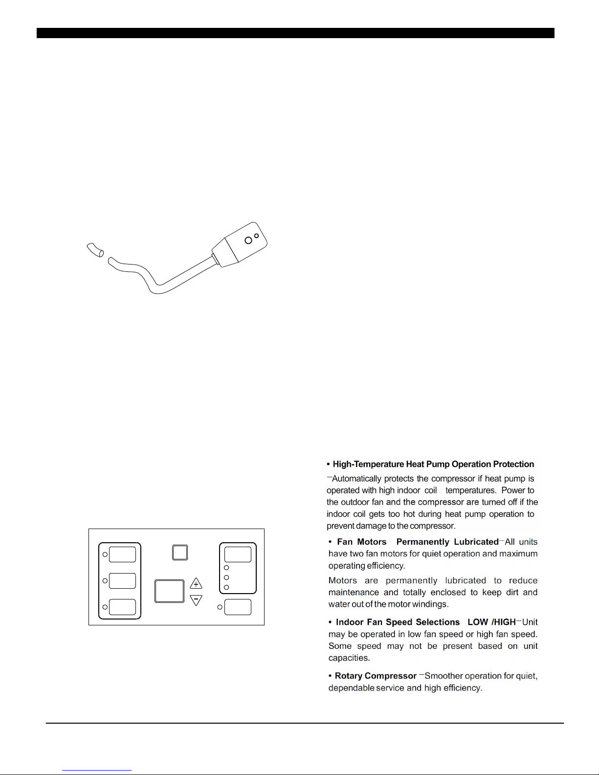
• LCDI Cords-Underwriters Laboratories and the
National Electric Code (NEC) now require power
cords that sense current leakage and can open the
electrical circuit to the unit on units rated at 250 volts
or less. In the event that unit does not operate, check
the reset button located on or near the head of the
power cord as part of the normal troubleshooting
procedure.
LCDI pow er Cord
• Automatic 3-minute compressor lockout-After
the compressor cycles off, it will not restart for three
minutes.
• Random restart delay-To help eliminate power
surges after a power outage, the unit is equipped with
a two to four minute random restart delay feature.
Whenever the unit is plugged in with the master
switch turned on and the mode switch set in the cool
or heat mode, a random restart will occur. A random
restart condition can be avoided by setting the mode
switch in the fan only or off position before applying
power to the unit.
• Indication LEDs-The control panel has LEDs that
correspond to fan operation and to indicate unit
status. The LEDs next to the selections ON/OFF,
FAN, COOL, and HEAT indicate which operational
-2 -
HEAT
COO L
FAN
ON/ OFF
AUT O
LOW
HIG H
SPEE D
FAN
Page 4
• Fan Motors Permanently Lubricated-All units
have two fan motors for quiet operation and maximum
operating efficiency.
Motors are permanently lubricated to reduce
maintenance and totally enclosed to keep dirt and
water out of the motor windings.
• Indoor Fan Speed Selections LOW /HIGH-Unit
may be operated in low fan speed or high fan speed.
Some speed may not be present based on unit
capacities.
• Rotary Compressor -Smoother operation for quiet,
dependable service and high efficiency.
• Indoor Coil Frost Control-Prevents indoor coil from
freezing. Frost can form on the indoor coil when the unit
is operated in cooling when the outdoor temperature is
low. The unit automatically shuts the compressor off
until the indoor coil temperature warms to the point
where frosting will no longer occur. Then restart the
compressor.
UNIT ACCESSORIES
This unit is designed for through-the-wall installation in
new or existing buildings. To complete the installation
of this PTAC, an insulated wall sleeve and an outdoor
grille (either the stamped aluminum grille, or the
architectural grille ) are required.
The chassis and the cabinet front are shipped in one
carton. Optional accessories to complete a particular
installation are the following:
OPTIONAL ACCESSORIES
Power switch Kit
Wall Sleeve Kit
Key Lock Kit
Drain Kit
Filter Kit
Hard Wire Kit
Wire Harness Kit
Architectural Grille Kit
Stamped Louver Kit
LCDI Power Cord
Wireless IR Antenna
Wireless IR Thermostat
Electric And Non Electric Sub Base Kit
IR REMOTE CONTROLLER
NOTE: Cons ult sale s lit erature for the approp ria te
volta ge and ampe rage sele ctions, i f applica ble.
-3 -
WARNING
HIGH VOLTAGE
DIS CONNECT AL L P O W E R BE FORE S E RVICIN G O R
INSTALL ING THIS UNIT. MULTIPLE POWER S OURCES MAY
BE PRESENT, FAILURE TO DO SO MAY CAUSE PROPERTY
DAMAGE, PE RSONAL INJURY OR DEATH.
Page 5
-4 -
WARNING
HIGH VOLTAGE
DI S C O N NECT AL L P O WER BEF ORE SE R V I CIN G O R
INSTALL ING THIS UNIT. MULTIPLE POWER SOURCES MAY
BE PRESENT, FAILURE TO D O SO MAY CAUSE PROPER TY
DAMAGE, PE RSONAL INJURY OR DEATH.
INSTALLATION INSTRUCTIONS
To ensur e th at t he unit o per ates saf ely and eff icientl y, it mus t be ins tall ed, operate d and mainta ined acc ording
to these instal lation and operat ing ins tructio ns and all local cod es and ord inan ces or, in the ir abse nce, wi th the
lates t edition of the Nationa l Electric Code. The proper ins tallati on of this unit is descri bed in the following
secti ons. Foll owing the s teps in the o rder pres ented sho uld ensur e proper in stallat ion.
WALL SLEEVE ASSEMBLY (OPT IONAL ACC ESSORY)
Two kind s of wall sle eve are opt ional for c ustomer s, one is rea ssemble w all sleev e and the oth er one is
weldi ng integr ated wall s leeve.
Remov able Wa ll Sleeve
The rem ovable wa ll sleeve c an be remov ed and occu pies l ess s pace a nd is c onve nie nt to tr ans port . Fol low th e
below s teps to ins tall :
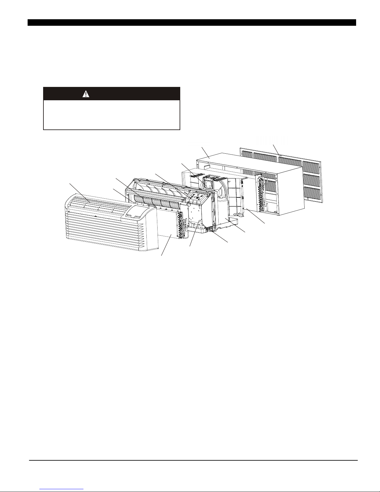
a) Unpa ck all part s and acces sories, r eferrin g to Fig 1.
b) Assem ble the wal l sleeve by f irst “cli p locking ” the side pi eces to the b ottom pie ce.
c) Assem ble the top p iece to the a ssemble d side and to p piece.
Weld ed integr ated wall s leeve
Weld ed integr ated wall s leeve is fe atured by a rtistic a ppea ran ce and s tab le str uct ure re fer ring t o Fig 2 .
Custo mers can pu rchase to gether wi th unit.
Fig 1
K
C
O
L
I
P
L
C
M
O
T
T
O
B
E
V
E
E
L
S
E
C
I
E
P
Front and discharge grille
Electric heater
Indoor Fan
Display Module
Outdoor Fan
Wall sleeve
Indoor coil
Control box
Power cord coverplate(not show)
Rotary compressor
Outdoor coil
Outdoor grille
Fig 2
4
2
"
1
6
"
"
3
1
3
4
Page 6

In order for condensate water to drain properly inside the
unit, the sleeve must be installed properly:
Level from right to left.
A slight downward pitch from the indoor side to the
out-door side as shown below .
•
•
(Fig 6)
• Fasten the wall sleeve(Fig 7).
-5 -
SLEEVE INSTALLATION
Preparation of the wall
The sleeve should be installed during construction and
lintels should be used to support the block above the wall
sleeve. The sleeve can not support the load of bricks/
blocks.
For existing construction, wall opening must be created,
the proper dimensions are necessary to avoid use of fillers
or additional framing .The sleeve is modular in height and
width(refer to Fig 5& Chart 2).
Height:
Fits 2 courses concrete block
Fits 6 courses standard brick
Fits 5 courses jumbo brick
Width:
Fit approximately 3 stud spaces.
Wall sleeve location
When making the wall opening, please observe the
following requirement:
A) The air inlet and outlet should be unblocked and the air
can be delivered to every corner of the room
B) Install the unit in places that are away from heat source
or sources of flammable gases.
C) Do not install the unit in places that are subject to strong
dust
D) Do not install the unit in places where the operational
noise and exhausted air might trouble your neighbour.
E) There should be sufficient space margins around the
unit to facilitate maintenance and repairs(refer to Fig 3
and 4)
NO.1
NO.2
minium finished opening
dimensions
sleeve dimensions
Heig ht
widt h
dept h
heig ht
widt h
16-1/4"
16-1/4"
16"
13-3/4"
(16"/18"/24")
42-1/2"
42-1/4"
42"
NOTE: NO.1 means using field supplied sleeve angles
NO.2 means not using field supplied sleeve angles
Fig 4
Fig 3
1
2
WOOD
SCREW
MOLLY
OR TOGGLE
BOLT
EXPANSION
ANCHOR
BOLT
MAIN STUD
JACK STUDS
HEADER-4"×4"OR
2-2"×4"ON EDGE
16-1/4"MIN
ADJUSTABLE FRAMING TO SECURE
THIS DIMENSION
42-1/4"MIN
SUB-FLOOR
FINISHED FLOOR
CRIPPLE
JACK STUD
Note:Do not remove the stiffener
support from inside the wall case
until the chassis is to be installed.
Fig 5
Inside
Outside
Level
Wall
Sleeve
Outside
Wall
1/4 Bubble
Tilt to
Outside
Proper Sleeve Tilt
Fig 6
Fig 7
Dimensions Recommended installation clearance
D1
D2
Projection of case into room-1/2"minimum up to1-3/4"maximum
without use of electrical sub-base.
Note: 2-3/8" minmum when sub-base is used.
Height above finished floor or top of carpet-1/2"minimum,
2" recommended without sub-base-3" minimum with sub-base.
Chart 1
Chart 2
Page 7

Cabinet Front Removal View 2
Cabinet Front Removal View 1
4. Secure the chassis to the wall sleeve using three screws
on each side of the chassis to ensure a proper seal
between the chassis and the wall sleeve. The screws are
supplied in a plastic bag.
IMPORTANT NOTES:
1. The unit is equipped with a rubber grommet mounted
compressor. These grommets are factory set and require
no adjustment.
2. Check the indoor and outdoor grilles for obstructions to
air flow. The unit must be located where curtains, furniture,
trees, or other objects do not block the air flow to and from
the unit. If air is obstructed and/or deflected back into the
unit, the air conditioner compressor may cycle on and off
rapidly. This could damage the compressor or possibly
void the warranty.
-6 -
OUTDOOR GRILLE
An outside grille must be installed to direct air flow for
proper unit operation and also protect the outdoor coil. The
grille must be installed before installing the chassis.
When replacing an old chassis with an existing grille or
using a specialized grille in a new installation, please
check with after-sales engineer of supplier to determine if
the new chassis should be used with the nonstandard
specialized grille. An improper outdoor grille can decrease
cooling or heating capacity, increase energy usage and
shorten compressor life and possibly void the warranty.
(OPTIONAL ACCESSORY)
FRONT REMOVAL
1. Grasp the cabinet front.
2. Pull the bottom of the cabinet front away from the
chassis until the retaining clips disengage.
3. Lift the cabinet front off the chassis. Reverse this
procedure to reinstall the cabinet front
Chassis Installation View 1
Page 8

VOLTAGE MEASUREMENTS
Once the unit is properly wired, measure the unit supply
voltage. Voltage must fall within the voltage utilization
range given in .Chart 3
WIRING
Cord connection to a wall socket is not permitted for 265V
units. All 265V units must be hard wired using the hard
wire kit or make use of the plug in receptacle in the
standard subbase.
230~208V units are equipped with LCDI power cords and
can open the electrical circuit to the unit. In the event the
unit does not operate, check the reset button located on or
near the head of the power cord as part of the normal
trouble shooting procedure.
WARNING
HIGH VOLTAGE
DISCONNECT ALL POWER BEFORE SERVICING OR INSTALLING
THIS UNIT. MULTIPLE POWER SOURCES BE PRESENT, FAILURE
TO DO SO MAY CAUSE PROPERTY DAMAGE, PERSONAL INJURY
OR DEATH.
DO NOT SERVICE THIS UNIT WITHOUT FIRST SHUTTING OFF THE
POWER TO THE UNIT FROM THE CIRCUIT BREAKER AND/OR
REMOVING THE UNIT CORD SET PLUG FROM THE WALL OUTLET.
WARNING
THI S A IR CO NDITI ONER IS NOT MEANT TO PROVI DE
UNATTEN DED COOLING O R LIFE SUPPORT FOR PERS ONS
OR ANIMALS WHO ARE UNAB LE REA CT TO THE FAILURE OF
THIS PRODUCT.
THE FAILUR E OF AN UNATTENDED AI R CO NDITIONER MAY
RESULT IN EXTREME HEAT I N THE CONDITIO NED SPACE
CAUSING OV ERHEATING OR DEATH OF PERSONS OR
ANIMALS.
Oper at in g Vol ta ge
Rati ng
230/ 2 08
265
Unit Voltag e
Mini mu m
197
238
Volt age Uti li za tion Ra ng e
Maxi mu m
253
292
Chart 3 -Operating Voltage
-7 -
RED-24VAC
Purple-LS control
Green-High fan speed
Blue-Reversing valve
Yellow-Compressor
White-Heater
Orange-Low fan speed
Black-Common ground
R LS GH B Y W GL C
R LS GH B Y W GL C
WALL MOUNTED THERMOSTAT INTERFACE
Thermostat
WARNING
TO AVOI D THE RIS K OF P RO PERTY DAMAG E, P ER SONAL
INJU RY OR , USE ON LY COP PE R CONDU CTOR S.FIRE
WARNING
TO AVO ID PR OP ERTY DA MA GE, P ER SONAL I NJ URY OR
DEATH DU E T O E LE CTRIC AL SH OC K, D O N OT USE A N
EXTE NS IO N CORD WI TH T HI S UN IT.
WARNING
TO AVO ID THE R IS K OF PR OPERT Y DA MAGE, PERS ONAL
INJU RY OR FIRE DO N OT I NS TAL L WITH PO WER CORD
STRE TC HE D OR UND ER A STR AIN AS TH IS M AY CREATE
LOOS E PL UG /R ECE PTACL E CO NN ECTIO N.
WARNING
TO AVOID THE RISK OF PERSONAL INJURY, WIRING TO THE
UNIT MUST BE PROPERLY POLARIZED AND GROUNDED.
Fig 9 wall mounted thermostat wiring
Fig 8 Receptacles/Sub-bases
NOTE: See the “ " before
use the thermostat.
Remote Thermostat Change instructions
Tandem
230/208V 15Amp
265V 15Amp
Perpendicular
230/208V 20 Amp
265V 20 Amp
Large tandem
230/208V 30Amp
265V 30Amp
Page 9

OPERATING INSTRUCTIONS ( A CCESS ORY OPTIO NAL )
HEAT
COOL
FAN
ON/ OF F
AUTO
LOW
HIGH
SPE ED
FAN
Oper at io n mode butt on s
Pres s th es e butto ns t o
sele ct t he u nit ope ra te o n
heat m od e, c ool mod e or f an
mode .
Oper at io n mode indi ca to r
lamp s
when t he u ni t opera te s on
heat o r co ol o r fan mod e th e
indi ca to r lamps w il l be
acti ve d.
Digi ta l di splay er
On nor ma l op erati on i t in dicat es r oo m tempe ra tu re;
When p re ss ing + or - bu tt on , it indi ca te s setti ng t em pe rat ur e ;
On tim e op er ation , it i nd icate s ti me r time;
On fai lu re o perat io n, i t indic at es f ailur e co de .
Fan Speed button
Press this button to select
the fan speed on high, low or
auto.
Fan speed indicator lamp.
Operation status indicator
lamp.
Rece iv er o f IR remo te c on troll er s ig nal
ON/OFF button
Press this button to turn the
unit ON or OFF.
WARM button
Pressing this button to set room
temperature warmer.
COOL button
Pressing this button to set room
temperature cooler.
Fig 10 Use of unit mounted control panel
-8 -
Fig 11 Use of hand held remote controller
Page 10

The vent control allows outside air to be drawn into the
conditioned area. This outside air can provide ventilation
when the blower is operating, but it will increase the
heating or cooling load and operating costs.
To obtain access to the vent control
1. Remove the cabinet front (see Front Removal).
2. Remove the shipping screw (if installed) from the vent
door.
3. Remove the label (if present) from over the vent control
lever on the left side of the chassis. Remove the vent door
shipping screw.
4. Rotate the vent control lever to either open or close
the damper.
Remo ve sh ipp ing
scre w if pr ese nt
Fig 13 Sh ipp ing Screw L ocation
TIMER PROCEDURE ( Remote controller)
When cells are inserted, the present time is automatically
set to AM 0:00.EX.:set to AM10:30.
Open the back cover, push the CLK button .The time
indicator is flickering and can set the present time.
Press the HOUR button.(set to AM 10:00)
Press the MIN button.(set to 30)
Press the CLK button again, and then close the back
cover.
COOL/FAN/HEAT MODE OPERATION
PROCEDURE
Control panel:
Press the ON/OFF button.
Press the HEAT COOL FAN button, select the operation
mode: heat cool fan.
Press + or - button, to set your desired temperature. The
setting temperature range is 60-90°F(16-32°C).
Press the FAN SPEED button, to set your desired air
flow rate: high/ low auto.
° °
auto
/ /
/ /
/
Remote controller:
Press the ON/OFF button with the remote controller
pointing toward the packaged terminal air conditioner.
Press the MODE button, select the operation mode:
cool/fan/heat.
Press + or - button, to set your desired temperature. The
setting temperature range is 61-88 F(16-31 C).
Press the FAN SPEED button, to set your desired air
flow rate:hig/ low/ .
VENTILATION CONTROL
The ventilation control lever is located at left side of unit,
behind front panel.
NOTE: The vent door shipping tape must be removed before
using vent control lever. See Fig 12 and Fig13.
When set at close, only the air inside the room is circulated
and filtered;
When set at open, some outdoor air will be drawn into room,
this will reduce heating or cooling efficiency.
-9 -
: unit control panel has control of unit.
: wall thermostat has control of unit.
67
R3
R1 R2
R4
R5
R6
R7
R8
Heating Temperature Limits(°F)
9086 86
74
92 90
72
90
72
63
65
72
69 68 60
Cooling Temperature Limits(°F)
Page 11

M O N T H LY M A I N T E N A N C E A N D
CLEANING
Intake Air Filters
To properly maintain the operational performance of
your PTAC unit, it is extremely important that the inlet
air filters be cleaned once per month or more often if
operated in dusty or dirty locations or conditions. The
inta k e ai r fi l te r s ar e const r u c te d of dur a b l e
polypropylene. The "air intake" air filters can be easily
inserted into the cabinet front, using the filter guides.
Before cleaning the intake filter, turn the unit off by
setting the mode switch to the OFF position. Filter
should be cleaned as required.
The following procedure is used to remove the intake
filler:
1. Grasp each filter by its molded handle, located on the
front edge of the front, below the discharge grill.
-10-
Locat ion of 7 Scre ws
Discharge Air Flow Grille Removal
4. Rotate the grille 180° clockwise
5. Reinstall the screws securing the discharge air grille to
the cabinet front. Reinstall the cabinet front on the unit.
WARNING
HIGH VOLTAGE
DI SCONN ECT ALL P O WER B E F O R E SE R V I C I N G OR
INSTALLING THIS UNIT. MULTIPLE POWER SOURCES BE
PRESENT, FAILURE TO DO SO MAY CAUSE PROPERTY
DAMAGE, PERSONAL INJURY OR DEATH.
Vent door lever positions
MAINTENANCE AND CLEANING
WARNING
HIGH VOLTAGE
DI SCONNE CT ALL P O WER B E F O R E SE R V I C I N G OR
INSTALLING THIS UNIT. MULTIPLE POWER SOURCES BE
PRESENT, FAILURE TO DO SO MAY CAUSE PROPERTY
DAMAGE, PERSONAL INJURY OR DEATH.
Discharge Air Flow
3. Remove the seven (7) screws which secure the
discharge air grille to the cabinet front.
AIR DISCHARGE GRILLE
The d ischarg e gril le can be a dju sted to expel a ir at
eithe r a 15°or 55°angl e。
Discharge Grille Orientation Options
15°
Disc har ge
Air
55°
Disc har ge
Air
Use the following procedure to change the angle of the
discharge air flow:
1. Remove the front cabinet (see Front Removal).
2. Position the front so that the backside is accessible.
Page 12

Vent Screen
Before cleaning the vent screen, disconnect power to the
unit by unplugging the power cord at the wall outlet or
subbase, or disconnect power at the fuse box or circuit
breaker. If unit is operated with vent door closed, the vent
screen does not need
to be cleaned.
1. Remove the cabinet front as described in Front
Removal.
2. Remove the six screws securing the chassis to the wall
sleeve.
3. Slide the chassis out of the wall sleeve far enough so
that the vent screen is accessible.
4. Clean the vent screen, slide the chassis back into the
wall sleeve, secure it in place with six screws and reinstall
the front cabinet.
Cabinet Front
The cabinet front and discharge air grille can be cleaned
with a water dampened cloth. Under no circumstances
should hydrocarbon-based cleaners (e.g. acetone,
benzene, naphtha gasoline, etc.) or ammonia based
cleaners be used to clean the front or air grilles. Use care
when cleaning the control area.
Y E A R LY M A I N T E N A N C E A N D
CLEANING
NOTE: Use a mild biodegradable detergent when
cleaning the unit. Special care must be taken to protect the
unit's control board and other electrical components from
getting any water on them while cleaning. The use of harsh
or caustic cleaning agents or materials such as bleach or
coil cleaners that are not designed for PTAC products will
cause damage or deterioration of the aluminum fin or coil
material and is not recommended. Care must be taken not
to bend the aluminum fin stock.
Base pan and Condenser coil
Before cleaning the base pan and condenser coil, turn
OFF unit mode switch and disconnect power to the unit.
To disconnect power, either unplug the power cord at the
wall outlet or subbase, or disconnect power at the fuse box
or circuit breaker
1. Create a water tight seal by tightly covering the entire
control panel area and fan motor with plastic. Creating this
seal prevents water from entering the control area or the
fan motor and damaging the unit.
2. Spray condenser coil and base pan down with water.
Next spray a mild biodegradable detergent onto the
condenser coil and base pan. Let set for five (5) minutes.
3. Rinse condenser coil and base pan with water again.
NOTE: Ensure water pressure is no higher than that of an
ordinary garden hose and the water temperature no higher
than 120°F.
-11-
Routine scheduled Maintenance
To achieve continuing top performance and high efficiency,
establish a “once a year" cleaning/inspection schedule for
the unit. Take the unit out of the sleeve and thoroughly
clean and rinse. Be sure to include in the yearly cleaning
the evaporator coil, and condenser coil, basepan, and
drain passages.
Scheduled maintenance can be accomplished by either
qualified local maintenance staff or by an authorized
servicer. They must follow the instructions described in this
manual.
Adverse Operating Conditions Maintenance
Units operating in dusty or corrosive locations; i.e.
dusty construction site or sea coast, must be cleaned
more often. A minimum of four (4) times a year will
maintain proper operational conditions and protect unit
components.
Wall sleeve
Clean the wall sleeve while cleaning the unit. The
caulking around the sleeve should be checked to make
sure that any potential air and water openings around
the sleeve are properly sealed. The wall sleeve's level
should also be rechecked. Proper leveling for most
installations are a 1/4 bubble tilt to the outside and
level from right to left. Contact your sales person for
detailed maintenance or cleaning instructions.
Fron t re mo val is no t
nece ss ar y to
remo ve t he f ilter
Filter is removed by grasping
the filter's top and gently
pulling up
2. Pull the filter straight up and remove.
3. Clean filter with vacuum or with running water.
Reverse this procedure to reinstall the filter.
CAUTION!
DO NOT USE COMMERCIAL GRA DE CO IL CLEANERS. SOME
OF THESE CLEANERS MAY CONTAIN ETHYLENE DIAMINE
TETRACET IC ACID (EDTA) WHI CH CAN SHORTEN TH E LIFE
OF THE CONDENSER COI L.
Page 13

4. Tilt the non-compressor side of the unit up no higher
than 45 degrees and allow water to drain out the other side
of the unit.
5. Remove excess water left in the base pan by wiping the
base pan with a dry cloth.
6. Remove the water-tight seal from the motor and
control panel area.
7. Reinstall unit back into wall sleeve.
8. Allow unit to dry for 24 hours before reapplying power.
When power is reapplied test unit for proper operation.
9. Place a non-acidic algaecide in the base pan to inhibit
bacteria growth. Ensure the algaecide is compatible with
wet coil operation and is not corrosive to the coil.
Clearance Check
Clearances around the unit should also be checked to
make sure that the intake air and discharge air paths have
not become blocked or restricted. A minimum of eight
inches clearance is needed from unit to furniture, beds, or
other objects for proper operation. Restricted discharge or
intake air will reduce the unit's operational performance. In
severe airflow restrictions damage can occur to unit
components such as the compressor, electric heater or fan
motor.
NORMAL OPERATING SOUNDS
AND CONDITIONS
Water trickling sounds
Water is picked up and distributed over the coil. This
improves the efficiency and helps with water removal.
Water dripping
Water will collect in the base pan during high humidity
days. This can cause overflow and drip from the outside of
the unit.
Air sounds
The fan cycle switch sets the operational mode of the fan.
In the ON position the fan will run continuously whenever
power is applied in this mode. In the AUTO position, the
fan will cycle on and off with the compressor or electric
heater.
Starting delay
You may notice a few minutes delay in the starting if you
try to restart the unit too soon after turning it off or if you
adjust the thermostat right after the compressor has
shut off. This is due to a built– in delay to protect the
compressor.
Buzzer Response
The buzzer will chime “Di”(0.1 sec) as response when
receiving the effective order from key pad control and
remote control.
DIAGNOSTIC CODES
Th e Diagn ostic Mainte nance provid es deta iled
information on PTAC control operation and operational
status including present modes, failures , airflow restriction
warnings , operating temperatures, and past failures.
To enter Diagnostic Status Report mode, press and hold
the down arrows and, while hold press the FAN SPEED
key for a period of five (5) seconds.
The meaning of figure on display pad is as below:
X.X----(0~4: time of protection)
└ ━ is protection mode(1: anti-frost; 2: overheat; 3: high
pressure; 4:anti-freezing)
-12-
Fail ur e co de
E2
E3
E5
E8
E9
Cont en t of d efect
Indo or c oi l te mpe ra tu re s ensor f ai lu re
Indo or t em pe rat ur e se ns or fa il ur e
Outd oo r co il t emp er at ur e senso r fa il ure
Over he at ing pro te ct ion/defr os ti ng
High p re ss ure pro te ct ion
CAUTION!
HIGH P RE SS URE AN D HI GH TEMP ER ATU RE CLEA NI NG I S
NOT RE CO MM ENDED .
DOIN G SO COULD DAM AG E THE ALUMINU M FIN STOC K
AND EL EC TR ICAL COMPON EN T.
Page 14

TROUBLESHOOTING
POSSIB LE CAUS ES
UNIT D OES N OT START
● Unit m ay ha ve be come un plu gge d
● Fuse m ay ha ve bl own
● Circ uit b rea ker may h ave b een t rippe d
● Unit m ay be o ff o r in wa ll ther mos tat m ode.
Ch e c k s e c ti on o n d ip s wi tch se tt in g s t o ve r if y
dips wit che s are set p rop erl y.
● Uni t m ay be in a pr ote ction or d iag nos tic fa ilure
mode . See s ect ion on di agn ost ic code s.
●
●
●
●
●
●
●
●
●
●
●
DISP LAY H AS ST RANGE NUM BER S/CHA RAC TER S
ON IT
UNIT M AKI NG NOIS ES
UNIT N OT CO OLING / H EATING R OOM
Unit a ir di sch arge se cti on is b locke d
Temper atu re se tting i s not h igh o r low eno ugh
Note : S etpoi nt limit s may not all ow the u nit t o h eat o r
cool the ro om t o the t emp eratu re d esi red. C hec k
sect ion o n dip switc h set tin gs.
Unit a ir fi lte rs are di rty.
Room i s exc ess ively h ot or c old w hen uni t is st arted
Vent do or le ft op en
Unit may be in a pr ote cti on or d iagnosti c fa ilure mod e.
Chec k sec tio n on Inte lli gen t Se lf -- - che cking C ont rol .
Comp res sor is in ti me del ay. Th ere is a pro tecti ve tim e
dela y (appr ox . 3 mi nutes ) on sta rti ng t he c omp ressor
afte r a powe r o utage (or re start ing afte r i t h as bee n
turn ed off ), to preve nt tripp ing of the compre sso r
over loa d.
WATER DRIPPING OUTSIDE
WATER DRIP PIN G INS IDE
Wal l sle eve is no t ins tal led lev el
ICE OR F ROS T FORMS O N IND OOR C OIL
Low ou tdo or te mpera tur e
Dirt y fil ter s
COMP RES SOR P ROTEC TIO N
Powe r may h ave c ycl ed, s o com press or is in a re sta rt
prot ect ion .
SOLUTI ONS
Chec k tha t plu g is plug ged s ecu rely in w all r ece ptacl e.
Note :Pl ug h as a test/ res et b utton on i t. M ake sure t hat the
plug h as no t tri pped.
Repl ace t he fu se.
Rese t cir cui t break er.
Tur n uni t on (bot tom r igh t butto n on ke ypad).
Note : If the u nit t urns on, t he LE D wil l be gr een . If th e u nit i s
off, the LED will be red. If there is no LED on, the re i s a
prob lem w ith p ower or d ama ge to t he cont rol .
Th e u n it may be i n a d iagn ost i c c ondi tio n. C hec k
--- ch eck ing Co ntr ol sec tion t o d ete rmi ne
if uni t has h ad a fa ilure .
The unit may b e set f o r ° C ( ins tead of ° F) , s ee th e key pad
conf igu rat ion sec tio n
Clic ki ng , gurg li ng and wh oo shing no is es a re n ormal du ri ng
oper at io n of unit .
Make sure that cur ta in s, blind s o r f ur ni ture are not rest ricti ng or
bloc ki ng u nit air fl ow.
Rese t to a l ow er or hig he r te mpera tu re s ettin g.
Remo ve a nd c lean fi lt er s.
Allo w su ff ic ie nt amou nt o f ti me for un it t o he at or coo l th e ro om.
Star t he at ing o r co ol ing e ar ly befo re outd oo r tem pe ra ture, c oo ki ng
heat o r ga th ering s of p eo ple mak e ro om u ncomf or ta ble.
Clos e ve nt d oor.
Chec k di ps witch s et ti ngs for d es ir ed comf or t.
Wai t ap pr oxi ma te ly 3 m inu te s fo r co mpres so r to s tart
If a drai n kit has not bee n install ed, conde nsa tio n runoff
duri ng ver y hot an d hum id wea ther is norma l. See Note 2. If
a d rai n kit h as b een insta lle d and is con necte d to a drain
syst em, che ck g ask ets and fitti ngs aro und drain for lea ks
and pl ugs .
Wal l sle eve m ust be insta lle d lev el for prope r dra ina ge of
cond ens ati on. C hec k tha t ins tal lat ion i s lev el and m ake any
nece ssa ry ad justm ent s.
When outdoor tem p e r a t u r e i s a p p r o x i m a t e l y 5 5 ° F
(12. 8°C ) or b elo w, f ros t may form o n the indoo r coi l when
unit i s in C ool ing mod e. S wit ch u nit t o FAN o peration u ntil
ice or f ros t mel ts.
Remo ve an d cle an filt ers .
Rand om Comp resso r re sta rt—Wh ene ver the unit is
plug ged in, o r p owe r h as bee n r estar ted , a rando m
comp res sor rest art will occur. Aft er a pow er outag e, the
comp res sor w ill res tar t aft er appr oxi mately 3 min ute s.
Comp res sor P rotec tio n — To preven t sho rt cy cling of the
comp res sor, t her e i s a r and om st art up de lay of 3 m inu tes
and a mi nim um co mpres sor r un ti me of 3 min ute s
●
●
●
●
●
diag nos tic co des
●
●
●
●
●
●
●
●
●
●
●
●
●
●
●
-13-
Page 15

Soleus Home Comfort warrants the accompanying Soleus Air PTAC to be free of defects in material and
workmanship for the applications specified in its operation instruction for the period of labor and parts
specified below.
This
warranty shall not apply to broken or marred cabinets, accessories, knobs, filters or routine maintenance.
This warranty does not apply to uncrating, setup, installation, removal of the product for repair or reinstallation of
of the product after repair.
This warranty does not apply to repairs or replacemen
Soleus Home Comfort including, but not limited to, any malfunction, defect or failure caused by or resulting from
unauthorized service or parts, improper maintenance, operation contrary to furnished instructions, shipping or
transit accidents, modification or repair by the user, abuse, misuse, neglect, accident, incorrect power line voltage,
fire, flood or other Acts of God, or normal wear and tear.
Warranty service must be performed by a qualified HVAC cont
service network to provide parts and assist in resolving service problems if difficulties are encountered.
Soleus Home Comfort agrees to provide service information, sell repair parts and reimburse the dealer /servicer for
parts and services in accordance with Soleus Home Comfort’s Policies and Procedures.
SOLEUS HOME COMFORT
MERCHANTABILITY ARE LIMITED TO THE TERMS AND CONDITIONS SPECIFIED ABOVE. SOLEUS HOME
COMFORT DISCLAIMS ANY LIBILITY FOR CONSEQUENTIAL OR INCIDENTAL DAMAGES AND IN NO
EVENT SHALL SOLEUS HOME COMFORT'S LIABILITY EXCEED THE RETAIL VALUE OF THE AIR
CONDITIONER.
This warranty covers only new products purchased from our
salvaged, refurbished products or internet sales.
FOR CUST
Soleus Home Comfort. 17911 East Ajax Circle, City of Industry, CA 91748. USA
Tel: 1-888-876-5387
Monday through Friday, 9:00 AM to 5:30 PM, PST
OMER
SERVICES, WARRANTY
5 YEARS FOR COMPRESSOR
1 YEAR FOR OTHER COMPONENTS
MAINT
AINS THAT ALL WARRANTIES, INCLUDING IMPLIED WARRANTY OR
WARRANTY
ts necessitated by any cause beyond the control of
ractor. Soleus Home Comfort maintains a centralized
authorized dealers or retailers. It does not cover used,
CLAIM AND PARTS PURCHASING, CONTACT:
Page 16

 Loading...