

Soleus Air HCB-R135-A-ID,HCB-R135-A-OD Installation And Operating Instructions Manual
13500 BTU RV Air Conditioner
Installation and Operating Instructions
Model No.:HCB-R135-A-ID
HCB-R135-A-OD
V140804
3092402

2
Thank you for choosing a Soleus Air RV Air Conditioner. This owner’s manual will provide you
with valuable information necessary for the proper care and maintenance of your new product.
Please take a few moments to thoroughly read the instructions and familiarize yourself with all the
operational aspects of your new Soleus Air RV Air Conditioner.
For your own records, please attach a copy of your sales receipt to this manual. Also, write the
store name/location, date purchased, and serial number below:
Store Name: ____________________________________________________
Location: _____________________________________________________
Date Purchased: _________________________________________________
Serial Number (located on back of unit): ______________________________
IMPORTANT INSTRUCTIONS
Before installing and using your RV Air Conditioner, please read this owner’s manual carefully. Store this manual in
a safe place for future reference.
1. All wiring must be complied with local and national electrical codes. All wiring must be installed by qualified
electricians. If you have any question about the following instruction, contact a qualified electrician.
2. Check the available power supply and resolve any wiring problems BEFORE installing and operating this unit.
3. This air conditioner is designed to operate from a 115V AC, 60Hz, 1 phase power supply.
4. This air conditioner is designed for recreational vehicles. Check the roof of the vehicle to determine if it can support both the roof top unit and the ceiling assembly without additional support. Make sure the interior ceiling
amounting area will not interfere with existing structures.
5. A reinforced and framed roof hole opening must be cut (if there is no hole) or you may use existing vent holes.
3
SPECIFICATIONS
MODEL NUMBER HCB-R135-A-ID HCB-R135-A-OD
COOLING CAPACITY 13500 BTU/Hr
DEHUMIDIFYING CAPACITY 132 pts per Day
COOLING POWER USAGE Cooling 1290 Watts, 11.6 Amps
AIR FLOW VOLUME(H/M/L) 490/400/346 CFM
POWER SOURCE 115 V / 60 HZ
SOUND PRESSURE LEVEL
Ceiling Assembly 50 dB(A)
Roof Top 58 dB(A)
Ceiling Assembly 5
0 dB(A)
Roof Top
58 dB(A)
P
RO
DUCT WEIGHT 1
0 lbs
92.3 lbs
O
P
ERATING
TEMPERATURE
Cooling 64.4℉-109.4℉
PRODUCT DIMENSIONS
26.25” W×19.5” D×3.625” H 41” W×22.375” D×14.5” H
REFRIGERANT R-410A

4
PRODUCT DIAGRAM
ROOF TOP
1. Roof Top Air Conditioner (1)
2. Sponge Air Duct (1)
3. Sponge Pieces (2)
4. Sponge Slip (1)
CEILING ASSEMBLY
1. Ceiling Grille (1)
2. Bolts (4)
3. Fabric Air Duct (1)
4. Air Vent Plates (2)
5. Remote Control (1)
6. Double-Sided Tape (1)
7. Remote Control Holder (1)
8. AAA Batteries (2)
9. Tapping Screws (8)
10. Remote Control Holder Screws (2)
11. Product Manual (1) (Not shown)
ROOF TOP
CEILING ASSEMBLY

5
ELECTRIC DIAGRAM
CEILING ASSEMBLY
ROOF TOP
6
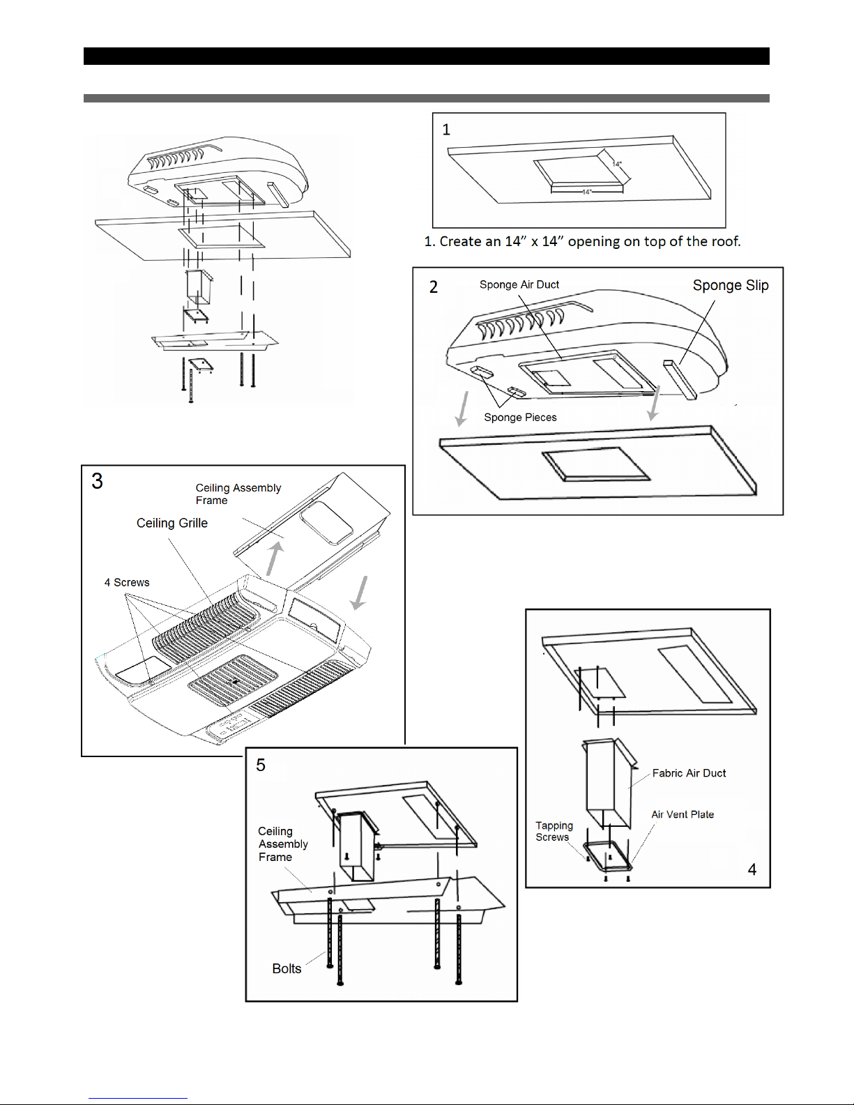
RVAC INSTALLATION INSTRUCTION
5. Fasten the Ceiling
Assembly Frame to
the base of the Roof
Top Air Conditioner with
the 4 Bolts.
4. Fasten the Fabric Air Duct to the base
of the Roof Top Air Conditioner with 4
Tapping Screws by Air Vent Plate.
2. Mount the Roof Top Air Conditioner on
top of where the opening was created.
3. Unscrew the screws and remove
Ceiling Assembly Frame from Ceiling
Grille.
 Loading...