

Page 1
Model No. GM-PAC-10E2
10,000 BTU Portable Air Conditioner
Operating Instructions
Page 2

Thank you for choosing a Soleus Air Powered by Gree Portable Air Conditioner. This owner’s manual will provide you with valuable information necessary for the proper care and maintenance of your
new product. Please take a few moments to thoroughly read the instructions and familiarize yourself
with all the operational aspects of your new Portable Air Conditioner.
For your own records, please attach a copy of your sales receipt to this manual. Also, write the store
name/location, date purchased, and serial number below:
Store Name: ____________________________________________________
Location: ______________________________________________________
Date Purchased: _________________________________________________
Serial Number (located on back of unit): ______________________________
IMPORTANT INSTRUCTIONS
Before installing and using your portable air conditioner, please read this owner’s manual carefully. Store this
manual in a safe place for future reference.
1) Alway
2) Never use or store gasoline or other flammable vapor or liquid near this unit unless instructed by this
3) Maintain at least 10 inches (25 cm) clearance space around this unit. Do not block or cover air inlet or
4) The unit must be connected to a correctly grounded power supply.
5) Do not start or stop the unit by inserting or pulling out the power plug.
6) Do not use an adapter plug or extension cord.
s place the unit on a level surface.
manual.
outlet grilles.
7) Do not use the unit in the immediate surroundings of a bath, a shower or a swimming pool.
8) Do not insert anything into the air outlet. Do not obstruct air inlet or outlet grills unless instructed by this
manual.
9) Do not let children play near this unit.
10) Always inspect the cord for signs of damage before use. If the power cord is damaged, it must be replaced
by the manufacturer or a qualified service technician.
11) When cleaning the unit, always turn the unit off and unplug the power cord.
12) Avoid using heating appliance near the air conditioner.
2
Page 3
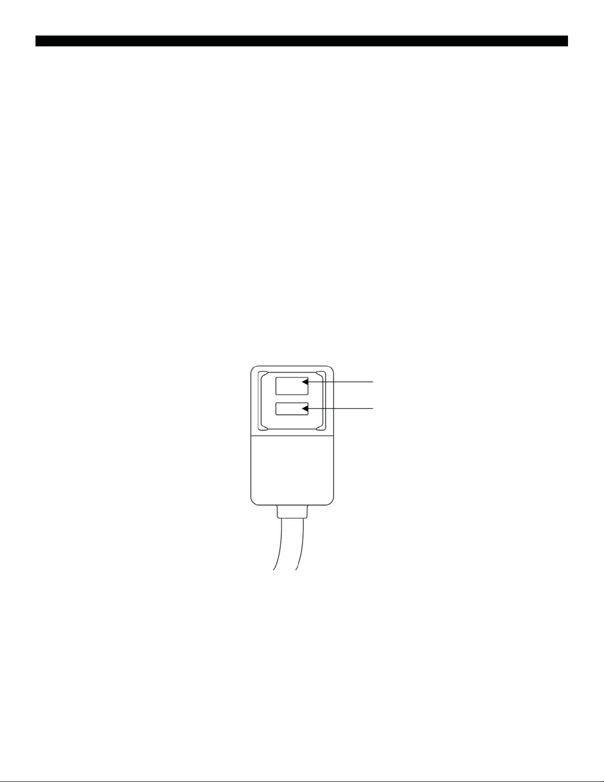
LCDI POWER CORD AND PLUG
This air conditioner is equipped with an LCDI (Leakage Current Detection and Interruption) power cord and
plug as required by US National Electric Code 440.65. This cord consists of a length of shielded flexible cord
with no termination on the load side and a LCDI attachment plug on the line side.
The LCDI power cord and plug will rem
nominal current leakage between the cord shield and either load conductor exceeds a predetermined value.
The cord will remain de-energized until the devise has been manually reset. This is intended to reduce the risk
of a fire in the power cord or combustible materials nearby. The cord shields are not grounded and they must
be considered a shock hazards if exposed. The cord shield must not be connected to ground or to any exposed
metal.
The test and reset buttons on the LCDI Plug are used to check if the plug is functioning properly. To test:
1. Plug power cord into wall outlet
2. Press TEST Button, circuit should trip, cutting power to the air conditioner
3. Press RESET button for use
If a test is performed and the indicator light remains ON, current leakage has been detected. Do not use the air
conditioner or attempt to reset the LCDI Plug. Contact Soleus Air Powered by Gree Customer Service for troubleshooting recommendations.
WARNING:
1. DO NOT press the TEST button while the air conditioner is operating.
2. The TEST and RESET buttons should not be used as ĀONāand ĀOFFāswitches.
3. The cord and plug are not intended to offer protection to externally connected loads or supply circuits.
4. The cord and plug are intended for indoor use only.
ove the supply source via electrical disconnect (circuit trip) if the
RESET
TEST
3
Page 4
INCLUDE
INCLUDE
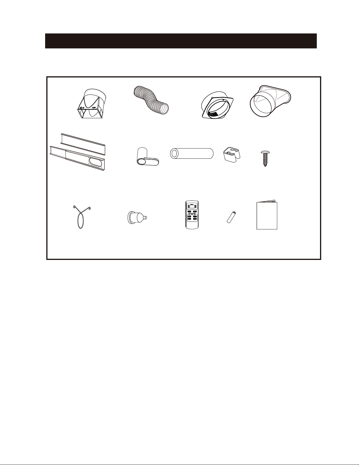
PARTS INCLUDED
Window Exhaust Adapter A
Adjustable Window Slider
Hose clip(2) Rubber plug
(3)
Exhaust Hose
Power cord
hoo k ( 2)
SUGGESTED TOOLS FOR WINDOW PANEL
1. Screwdriver(medium size Phillips) 2. Tape measure or ruler 3. Knife or scissors
4. Saw (In the event that the window panel needs to be cut down in size because the window is too narrow for
direct installation.)
Window Exhaust Adapter B
Drain hose Hose Clamp
Remove control
Battery
(AAA.1.5V)
INSTALLATION
Window Exhaust Adapter C
Screw (7 )
(2 )
Manual
4
Page 5
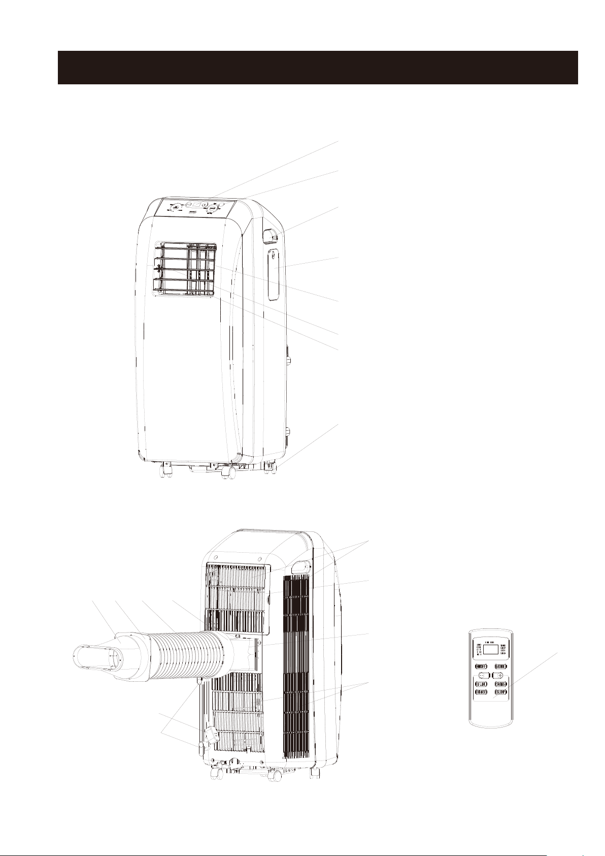
STRUCTURE
1
Front
2
1, Control panel and display lamp
2, Remove control signal receiver window
3
3, Handel
4, Remote controller box
5,
Air outlet
6, Vertical louvers
4
7, Horizontal louvers
8, Wheel
9, Air inlet
10, Grille
5
11, Air outlet
12,Air inlet
6
7
13,Power cord hook
14, Power cord
15, Window exhaust adapter A
16, Exhaust hose
17, Window exhaust adapter
18, Window exhaust adapter
B
C
19, Remove control
8
18
17
16
Rear
9
10
15
11
19
12
14
13
5
Page 6
PACKAGE CONTENTS
Portable Air Conditioner
Exhaust Hose (1)
Window Exhaust Adapter A (1)
Window Exhaust Adapter B (1)
Window Exhaust Adapter C (1)
Remote Control & AAA Batteries (2 batteries)
Window Kit - 3 Sliding Panels (1 single hose panel, 2 extension panels)
Drain Hose Assembly (drain pipe, hose clamp, hose clip, rubber plug, & screw)
Power cord hooks (2hooks & screws)
Owner’s Manual
SPECIFIC
The cooling capacity is measured at an am
x
Noise level is measured at a distance of 3.28 ft away from the front of the unit, when the unit is
x
x
Power consumption is measured when the fan runs at the highest speed setting.
These specifications are for reference only. For actual data, please refer to the rating label on the back of the unit.
x
If the environment temperature is higher than the max operating temperature or lower than the minimu
x
ATIONS
bient temperature of DB 95 °F, WB 83 °F.
in cooling mode.
m operating
temperature, the air conditioner may not work properly.
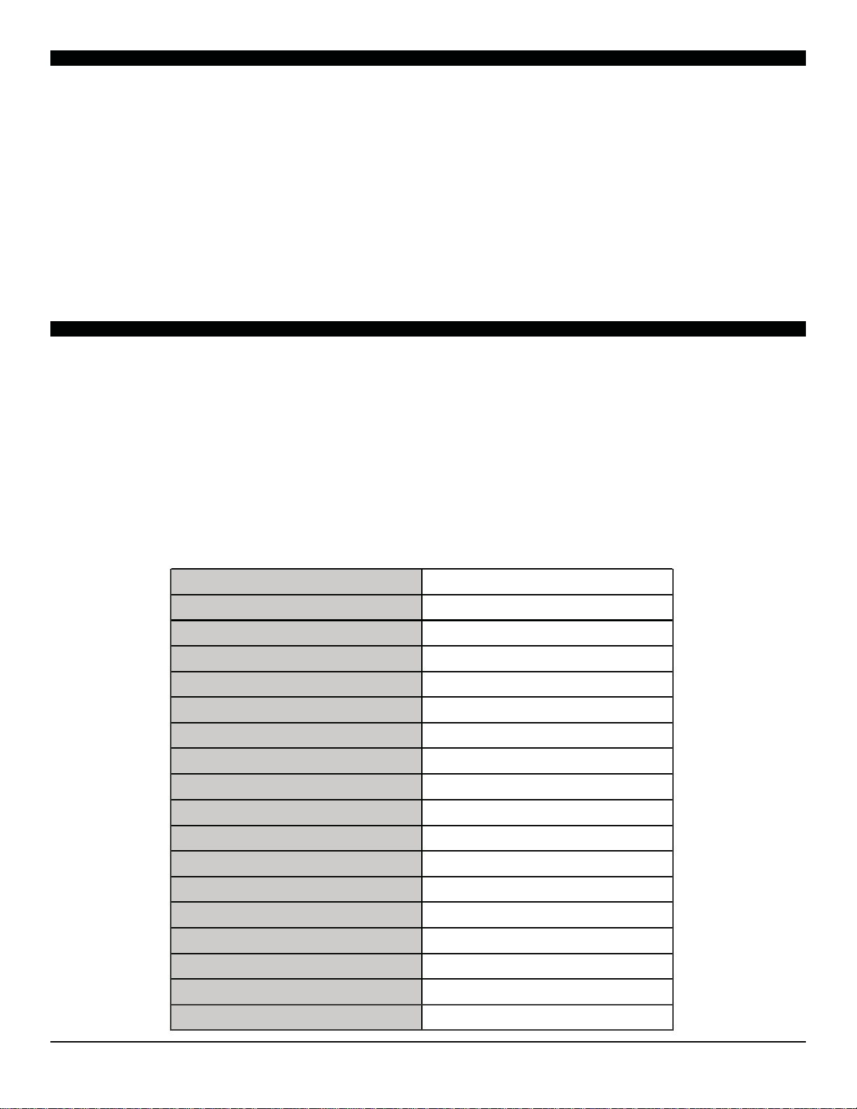
Model Number
Power Supply (Ph/V/Hz) 1/115/60Hz
Dehumidifying Capacity (Pints/Day) 60
Rated
Cooling Capacity (B
Rated Heating Capacity (BTU/h) /
Cooling Power Input (Watts) 1120
Heating Power Input (Watts) /
Rated Current Cooling (Ampera
TU/h) 10
ge) 9.9
GM-PAC-10E2
,000
Rated Current Heating (Ampera
EER/C.O.P /
Noise Level db (A) H/L <=53
CFM 176
Design Pressure (PSIG) (H/L) /
Dimensions (W” x H” x D”) 13.375X30.75X15.5
Package Dimensions (W” x H” x D”)
Net/Gross Weight (Lbs) 53/66
Refrigerant Type R-410A
Refrigerant Charge (Oz) 17
ge) /
15.75 X 32X 21.75
6
Page 7

INSTALLATION OFTHE POWER CORD HOOK
Attach the hooks to the back of air conditioner with the screws.
•
hoook
screw
•
Wind the power cord round the power cord hooks.
7
Page 8

PARTS & WINDOW KIT ASSEMBLY
PARTS
EXHAUST HOSE & ADAPTERS
Exhaust Hose Adapter
Exhaust Hose
Hose
Adap
ter
ASSEMBLY & INSTALLATION
INSTALLATION
When the unit is operating as an air conditioner or dehumidifier, the window kit and exhaust hose mu
When the unit is operating in fan mode, the window kit and exhaust hose do not need to be installed .
MOUNTING THE EXHAUST HOSE
x
x
x
x
x
Choose a suitable location, near a grounded electrical outlet and suitable window or door. Remove
packaging and locate components.
Extend both ends of the exhaust hose approximately 6 inches.
Screw the window kit adapter onto one end of the exhaust hose clockwise. Screw the hose adapter onto
the other end of the exhaus
Mount the exhaust hose onto the back of the unit by l
For maximum
efficiency do not bend the hose as much as possible.
t hose clockwise.
ocking the hose adapters into place.
st be installed.
8
Page 9

SINGLE HOSE WINDOW KIT INSTALLATION
This installation is OK The is a poor installation
26”
22”
When installing the exhaust hose, try and keep it as flat as possible. The less angles and bends
in the hose, the better the unit will perform. If bending or an angle is necessary, use single 90°
angles like the pictures above. Multiple bends will decrease performance and efficiency
9
Page 10

CONTROL PANEL DISPLAY & OPERATING INSTRUCTIONS
CONTROL PABEL & DISPLAY
Temperature selection button
Fan speed button
LED window
COOL mode lamp
MODE buttonFAN mode lampFAN Speed lamp ON/OFF button
Receiver window
DRY mode lamp
OPERATING INSTRUCTIONS
When pressing key is valid, buzzer makes a sound, indicate dlamp indicates relevant state, syste mwill last for
2 seconds.
ON/OFF Button
l.
Press the button once to manually turn the unit on. Press once more to turn the unit off.
2. "+","-"
In COOL mode, press "-" once, the set temperature will decrease 1
incresae 1C ( F).The set temperature rang from 16 Cto 30 C(61 F to 86 F)
Button
C
, press "+" once, the set
(F)
temperature will
3.MODE Button
Press MODE Button repeatedly to cycle between the modes:Cooling,Dry,and Fan only mode.
the MODE
be installed when the
exhaus
button will light up a different lamp on the control panel. The exhause
t hose and window kit
unit is in Co
connected to the unit.
olor Dry mode.When using the unit
as a fan,it is unnecessary to keep the
hose and window kit must
Each press of
4. Fan speed
Button
When the unit is running in Cool or Fan mode,press the Fan speed Button to select the fan speed
Middle, Low , Auto.
comfortable.
In cool mode, it can decrease the temperature of the room, and make people very
5.Water Full
When COOL or DRY is running, condensate will drain to
times, LED screen show error code ‘H8’.
In this case, reference page 8 to drain out water intank.
6. Louver Direction
This unit has 4-Way directional louvers.
Use the louver guides to direct air where
cooling or fanning is needed most.Hold the
louver and adjust the air flow direction,
as show in the right diagram.
water tank. When water tank is filled. buzzer will sound 8
Hold this hand grip to adjust the
direction of Horizontal Louvers
Hold this hand grip to adjust the
direction of Vertical Louvers
in High,
10
Page 11

HOW TO USE THE REMO
Point the remote control towards
the units signal receiver window
and pres s th e des ire d button. A
beep will sound when the unit receives the signal.
blocks the signal receiver window.
For good receive, the distance between
operator and the unit no more than 5
meters.
CAUTION
its operation. If necessary , close the curtains to block out the sunlight.
VCRs or other equipment used in the same room.
V
E CONTROL
remote control from moisture and shock which can discolor or damage it.
11
Page 12

REMOTE CONTROL OPERATING INSTRUCTIONS
NOTE
: Heat
mode is not av
on this unit
ailable
POWER BUTTON
FAN BUTTON
SLEEP BUTTON
1) Power On and Off - Press the ON/OFF (POWER) button once to m
more to turn the unit off. When you manually power the unit on and off by pressing the ON/OFF button, the preset timer will
be cancelled.
anually turn the unit on. Press the Power button once
LCD DISPLAY and
MODE LABELS
MODE BUTTON
TEMP SELECT BUTTONS
SWING BUTTON
(Not Available on this unit)
TIMER BUTTON
2) Mode Selection
midifier, and Fan only mode. Once a mode is selected, an arrow will light up on the LCD display next to the selected MODE
label on the remote. Auto mode automatically chooses the air conditioner, dehumidifier, or fan mode based on the current room
temperature.
3) Fan Speed
depending on which speed is selected. The more fan icons light up, the higher the speed. The fan icons are located on the LCD
display next to the SPEED label.
4) Temperature Setting
SELECT buttons (+ or -) to select your desired temperature setting. The temperature on the LCD display on the remote control
will increase or decrease accordingly. Hold the +/- buttons for two seconds to rapidly increase or decrease the temperature.
- Press the MO
- Press the FAN speed button t
- When the unit is in Air Co
DE Button re
o cycle through low, medium, and high fan speeds. The small fan icons will light up
peatedly to c
nditioner mode you can select your desired temperature. Press the TEMP
ycle between the different modes: Auto, Air Conditioner, Dehu-
NOTE: HEAT MODE
NOT AVAILABLE
12
Page 13

REMOTE CONTROL OPERATING INSTRUCTIONS (Cont.)
5) Auto-on Timer: When the air conditioner is off, it can be set to automatically turn on in 30 mi
set mode and fan setting. To set the Auto-on Timer, press the TIMER button on the unit or remote control. Each touch of the +/-
buttons on the remote will change the timer setting in 30 minute increments (.5 hours). The T-ON and H lights will blink while
the Auto-on Timer is being set. Once the timer is set, press the TIMER button once more to save the setting. Press the ON/OFF
button to cancel the timer.
Auto-off Timer:
Auto-off Timer, press the TIMER button on the remote control. Each touch of the +/- buttons on the remote will change the
timer setting in 30 minute (.5 hour) intervals. The T-OFF and H lights will blink while setting. To cancel the timer, press the
ON/OFF button. Once the timer is set, press the TIMER button once more to save the setting. Press the ON/OFF button to
cancel the timer.
6)
Sleep Mode
When the air conditioner is on, it can be set to automatically turn
- Press the SLEEP mode button to engage SLEEP mode. Sleep mode automatically reduces the
off in 30 minutes to 24 hours. To set the
nutes to 24 hours at the previous
set temperature by 2°F after one hour and 4°F after two hours. This feature limits compressor usage and
enhances energy savings while you are sleeping.
7)
Auto Mode
- When AUTO mode is selected the air conditioner will automatically choose the operating
mode base on the current room temperature. When the room is below 68°F the air conditioner will
automatically fan the room to circulate air. When the room temperature is between 68°F-73°F the air
conditioner will operate in Fan mode if it was previously selected or dehumidifier mode (if another mode
was used previously) to remove humidity from the air as well as some cooling to help lower the room
temperature. When the room temperature is between 74°F-79°F the air conditioner will always operate in
dehumidifier mode. When the room temperature rises above 79°F, the unit will operate in air conditioner
mode to maximize cooling. Auto mode uses pre-determined settings to keep you comfortable by choosing
the most energy efficient mode based on the temperature of the room.
13
Page 14

DRAINING COLLECTED WATER
When the temperature or humidity is too high, the air conditioner may not be able to evaporate all of the water
as quickly as needed. All moisture that is unable to be evaporated is placed in a small bank up water tank inside the unit. When this tank is completely full, an alarm will sound, the compressor will shut off, and the
bucket full icon will light up on the control panel. To manually empty the tank, please follow the instructions
below.
Drain Hose
Clamp
Drain Hose Clip
Drain Plug
Screw
1) Remove the pre-installed Drain Cap from the unit (See Below).
2) Attach the Clamp with the provided Screw (See Below).
A. Drain Port
B. Drain
Cap
B
A
A
A. Drain Port
B. Clam
B
p
3) Attach the Drain Hose to the Drain Port using the Drain Hose Clip. Insert the Drain Plug into the free end
of the Drain Hose and guide the Drain Hose through the Clamp. Once finished, the unit can be easily
drained by removing the drain plug and guiding the drain hose into a small pan to drain the water.
A
A. Drain Plug
B. Drain Po
C. Drain Hose
rt
E
D
C
B
D. Drain Hose Clip
E. Clamp
14
Page 15

MAINTENANCE
Note: Make sure power is off and the power cord is not plugged into an electrical outlet prior to
performing any maintenance on the unit.
Clean or replace filter - If the air filter is blocked with a dust, the airflow volume may reduce. It is
recommended to clean the filter once every two weeks or as needed.
1) Remove the filter from the filter compartment on the back of the unit.
2) Wash the air filter by immersing it gently into warm water with a neutral detergent. Rinse the filter
and dry it thoroughly out of sunlight.
3) Slide the filter back into the filter compartment after it is thoroughly dried.
4) If the filter is torn or unusable, order a new filter by calling the customer service number on the
warranty page of this manual.
Clean the unit Housing
1) Keep the unit from being exposed directly to the sun to prevent color fading.
2) Clean the surface with a damp cloth and dry it with a soft towel.
Storing the Unit for an Extended Period of Time or Transporting the unit
1) Empty any excess water by unplugging the water drainage stop in the back of the unit (located at
the bottom).
2) Unplug the unit.
3) The unit should be stored in a cool dry place.
DISCLAIMER
ALL INFORMATION AND THE TECHNICAL SPECIFICATIONS PRESENTED IN THIS USER’S MANUAL ARE THE
PRESENTATION OF THE MANUFACTURER. SOLEUS INTERNATIONAL HAS NOT CONDUCTED I
TEST TO THE INFORMATION AND THE SPECIFICATIONS PRESENTED HEREWITHIN.
NDEPENDENT
15
Page 16

TROUBLESHOOTING
PROBLEM
The Air Conditioner will not start
POSSIBLE CAUSES
The air conditioner is unplu
connected well.
gged or not
The fuse is blown/circuit breaker is
tripped.
Power Failure
The current interrupter device is
tripped.
SOLUTIONS
x Make sure the air conditioner plu
is pushed completely into the outlet
x Check the house fuse/circuit
breaker box and replace the fuse
or reset the breaker.
x The unit will automatically re-start
when power is restored.
x There is a protective time delay
(approx. 3 minutes) to prevent
tripping of the compressor
overload. For this reason, the unit
may not start normal cooling for 3
minutes after it is turned back on.
x Press the RESET button located
on the power cord plug.
x If the RESET button will not
engaged, discontinue use of the
air conditioner and contact a
qualified service technician.
stay
g
The Air Conditioner does not cool
as it should
The Remote Control is not working
Airflow is restricted
The temperature control may not be
set correctly.
The air filter is dirty
The room may be too warm
Cold air is escaping
The Evaporator is frozen
The batteries are inserted inco
The batteries may be dead
rrectly
x Make sure there are no
blinds, or furniture blocking the
front of the air conditioner
x Lower the set thermostat tempera-
ture
curtains,
x Clean the filter. See the Cleaning
and Care Section of the manual.
x Please allow time for the room to
cool down after turning on the air
conditioner.
x Che
ck for open furnace registers
and cold air returns
x The unit is defrosting and
sume oper
x Check the position of the batteries.
x Replace the batteries
ati
on wh
en done.
will re-
16
Page 17

TROUBLESHOOTING (CONT.)
PROBLEM
The LCD Display is showing “E5”
The LCD Display is showing “H8”
POSSIBLE CAUSES
Low Voltage Protection
The backup water tank is full
SOLUTIONS
x Unplug for 10 minutes and then
turn on the unit. If “E5” is still displayed, contact customer service.
x Drain the water tank
x If the “H8” I still displayed after the
water tank has bee
tact customer service.
n emptied, con-
17
Page 18

WARRANTY
One Year Limited Warranty
Soleus International Inc. warrants the accompanying Soleus Air Powered by Gree Portable Air Conditioner to be free of
defects in material and workmanship for the applications specified in its operation instruction for a period of ONE (1)
year from the date of original retail purchase in the United States.
If the unit exhibits a defect in normal use, Soleus International Inc. will, at its option, either repair or replace it, free of
charge within a reasonable time after the unit is returned during the warranty period.
As a condition to any warranty service obligation, the consumer must present this Warranty Certificate along with a
copy of the original purchase invoice.
THIS WARRANTY DOES NOT COVER:
•
Damage, accidental or otherwise, to the unit while in the possession of a consumer not caused by a defect in
material or workmanship.
•
Damage caused by consumer misuse, tampering, or failure to follow the care and special handling provisions
in the instructions.
Damage to the finish of the case, or other appearance parts caused by wear.
•
Damage caused by repairs or alterations of the unit by anyone other than those authorized by Soleus Interna-
•
tional Inc.
Freight and Insurance cost for the warranty service.
•
ALL WARRANTIES, INCLUDING ANY IMPLIED WARRANTY OF MERCHANT ABILITY ARE LIMITED TO
ONE-YEAR DURATION OF THIS EXPRESS LIMITED WARRANTY. SOLEUS INTERNATIONAL INC.
DISCLAIMS ANY LIABILITY FOR CONSEQUENTIAL OR INCIDENTAL DAMAGES AND IN NO EVENT
SHALL SOLEUS INTERNATIONAL INC’S LIABILITY EXCEED THE RETAIL VALUE OF THE UNIT FOR
BREACH OF ANY WRITTEN OR IMPLIED WARRANTY WITH RESPECT TO THIS UNIT.
This warranty covers only new products purchased from our authorized dealers or retailers. It does not cover used, salvaged, or refurbished products.
As some states do not allow the limitation or exclusion of incidental or consequential damages, or do not allow
limitation on implied warranties, the above limitations and exclusions may not apply to you. This warranty gives you
specific legal rights, and you may also have other rights that vary from state to state.
For Technical Support & Warranty Service
Please Call (888) 876-5387
Or Write To:
Soleus International Inc.
20035 E. Walnut Dr, North.
City of Industry, CA 91789 USA
www.soleusair.com
18
 Loading...