

Page 1
Please read Owner’s Manual carefully
before operating the unit
.
Page 2
Main technical parameter of RT-135
Capability Unit Value
Operating
Capabilities:
Cooling
Operating
capabilities:
Heating
Air Flow Volume
Cooling Capacity Btu/h 13500
Watts W 1220
Rated Full Load Current A 11.2
Heating Capacity Btu/h 14400
Watts W 1620
Rated Full Load Current A 14.8
CFM 412/235
Power Supply 115VAC/60HZ/1Phase
Operational Range-Cooling
Operational Range-Heating
Noise
Level
Refrigerant / Amount
Net Weight
Inside The Room
Outside The Room dB(A) 62
Top Mount Unit 103.5
Indoor Unit
F 61 to 115
F 17 to 90
dB(A) 51
ounce R22 / 42
lbs
7.5
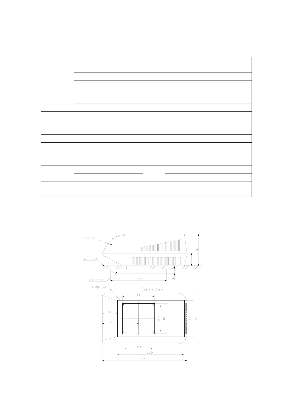
Top Mount Unit In 44(W) ×28 3/4(D) ×14 3/4 (H) Assembled
Dimensions
Indoor Unit In 21 1/2(W) ×20 1/2(D) ×3 1/4(H)
RT-135 series dimensions (Unit: In)
SOLEUSAIR
A
1
Page 3
Use
RT-135 series air-condition have the capability of cooling / heating / ventilation and
dehumidification and contain the character of resisting shake attrition and high-dependability. It
can be used for applications such as RV units, trucks & vans, small-scale shipping vehicles & farm
equipment.
Structure and character
Structure
This air conditioning is in the top of structure
Main components include evaporator, condenser, compressor, throttling device, air blower
system, protection cover, tunnel and the control panel in main cabin.
Character
1) Instant cooling/adjustable temperature: It can reduce the environment temperature in a
short time in order of passenger’s demand.
2) Continuously running in adverse condition.
3) Lengthy continuously running time in acid and alkali condition.
4) The Width & Height capability : The appearance and assembly size keep the same with
present products on the market and helps keep air flow fluent.
5) Quiet operation: Improve comfortableness, low noise.level.
6) Delay start: With sudden loss of power and rapid reset, compressor is time delayed for 3
minutes for protection
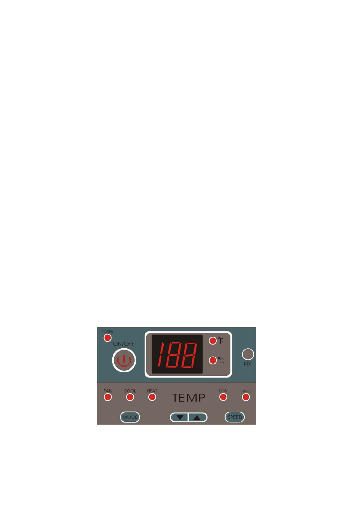
Control panel
2
Page 4
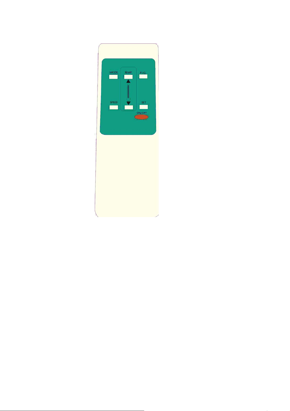
Remote device
Operation through the control panel or remote device
Through the control panel in the room, user can control all functions of the air-conditioner. The
parts of control contain the following functions:
1. Switch
The air-conditioner can be started or stopped by the button “ON/OFF”. The indicator lamp
“POWER” in the upper left corner is lighted when air-conditioner is running.
2. Choose button “MODE”
This button confirms the working status of the air-conditioner.
You can switch it in:”FAN” state, “COOL” state and “HEAT” state.
3. Temperature setting button “TEMP”
Through buttons “▲” and “▼”, you can increase and reduce the setting temperature in the
room.
4. Fan speed switch button “SPEED”
You can switch fan speed in “HIGH” or “LOW”.
5. Temperature showing “temperature”
In holding state, control panel shows present indoor temperature. The control panel shows
temperature in setting state. If you don’t press the “TEMP” key more than ten minutes, the
control panel will be back awaiting state and show present indoor temperature.
6. Push“SPEED+MODE”(in the control panel) or “SET”(in the remote device) into setting state
In this state you can set parameter with “▲” and “▼”.
3
Page 5

The scheme of refrigeration system
CONDENSER
FAN
COMPRESSOR
THROTTLE
EVAPORATOR
4
Page 6

Schematic circuit diagram
TRANS-OUT
+5V
GND
A
B
C
G
DAT
HEAT
CLK
REC
KEY
WAT1
WAT2
OPERATE PANEL
SENSOR1
SENSOR2
T
CONTROL PANEL
60HZ
110VAC
N
L
PE
12AWG
PE
1
C1
RE
GR
S
YE
+
~
GR
COMPFAN
R
MC
C
BL
KA1
FU2
LLNNNL-FAN NH-FAN
TRANS-IN
oncom
KA1
C2
2
3
20AWG
BL RE
WH
YE
MF
~
YE
WH
+
GR
4
PT
FU3
12AWG
HEATER
5
Page 7

Cautions
1. In any case the compressor will restart 3 minutes after power failure
2. The air-conditioner adopts three core plugs: Modification will void warranty
3. Working voltage of the air-conditioner must keep within the range of 115VAC±10. If the
voltage is too high or low will lead to damage of the compressor.
4. The normal working environment temperature of the air conditioner is: 0F to115F
Maintenance and Safeguard
It will keep at maximum performance ratings if you perform routine maintenance. After running
for 90 days, you must clean up dust around the fins of the heat exchanger in order to keep
refrigeration performance at optimum
TROUBLE SHOOT CHART
Problem Possible Cause Solution
Doesn’t cool / heat 1. The voltage of the power
is lower than 97V
2. You are using an
extension cord for the unit
3. The system leaks Fluorine
4. Button “ON/OFF” failure
5. Set the temperature to the
abnormal position.
6. Compressor not working.
7. The sub cooling of
compressor is protected
and does not work
8. Capillary is blocked
Inadequate cooling 1. The evaporator and/or
condenser are blocked by
debis .
2. The doors and windows
have opened frequently.
3. Heat load is too high.
4. Set temperature is in
improper position.
5. Capillary is blocked.
6. The refrigeration system
has failed.
Adjust the voltage range into
normal demand.
Do not use an extension cord.
Call repair technician
Replace button “ON/OFF”.
Refer to operation explanation.
Turn off for ten minutes. Turn
back on
Call repair technician
Call repair technician
Clean the evaporator and
condenser.
Reduce times that open the
door.
Installation of larger unit.
Adjust the set value.
Call repair technician
Call repair technician
6
Page 8

No heat 1. Power is off.
2. Set temperature is in
improper position
3. Connector has fallen off.
4. Heater is defective
5. Fuse is open.
6. Control panel is not
working.
The fan doesn’t operate 1. Control panel is faulty.
2. The capacitor of fan
defective.
3. Fan defective.
Unusual sound or heavy
shaking
1. Installation of the
air-conditioner too
gradient.
2. Fan touches with other
hardware.
3. The connective pipelines
collide with each other.
4. The part becomes flexible.
Check the circuit
Adjust the set value
Tighten the plug.
Change the heater.
Change the fuse.
Change the circuit panel.
Change the panel.
Change the capacitor.
Change the fan.
Check Installation.
Adjust the fan position.
Adjust the position between
the pipelines.
Tighten screws.
Installation
1. Installation preparation
If you need to install the air-conditioner on already existing roof vent, the measure of vent
must reach 14×14 (in). If it is not enough of this measurement, you must extend this
measurement. If it is larger than this measurement, you must make a wood frame for the vent
to meet above measurement.
The gradient of install the platform must no more than 5°. If greater than 5° it can be
influenced that condensation water of the air conditioner could overflow.
You must avoid any wire and any pipeline before incision.
2. Please directly install the top of the air-conditioner on the placket and make windward face
toward the front of the vehicle, condenser toward the back of the vehicle. Put the seal
between air-conditioner and placket, and you can sight the four M10 install bores in the
air-conditioner bottom. To those irregular coarse roofs you must have sealant seal up all gaps
in order to prevent rainwater infiltrating into room.
7
Page 9

3. You must make mounting hole on indoor installation frame align with the hole on the top of
the air-conditioner and tightly connect with 4-M10 special screw.
4. Install canvas-pipe
You must make the flange of the canvas-pipe align with air outlet of the top of air-conditioner
and connect them with screw, gasket, spring gasket and nut.
8
Page 10

5. Prepare installing of indoor equip: Disassemble the indoor equip.
6. Install the indoor unit
a) You must install the main of indoor tunnel and installation frame with four ST4.2X16
screw.
Caution: It can be rotated from +90°to -90°.
b) Installing the canvas pipe underparts
You must put into metal flange from canvas pipe under part and tightly nip main vent-pipe
and connect with ST4.2X16 screw. The surplus part is cut out.
c) Install covers board of vent-pipe and indoor main cover board.
d) Connect indoor plastic and gold with two M4×10 screws, gasket and spring gasket.
9
Page 11

Check
1. Check the complete installing manual to make sure unit is installed correctly and safe
2. Switch on the power, operate the air conditioner according to above methods. If it runs
improperly, for example abnormal noise, running current too high or no temperature, please check
owner’s manual.
10
Page 12

3. Clean up the installing rubbish and restore decoration to original decor.
11
Page 13

Warranty
Soleus International Inc. warrants the accompanying Soleus Air RT-135 Roof Top Air Conditioner to
be free of defects in material and workmanship for the applications specified in its operation
instruction for the period of labor and parts specified below.
5 YEARS FOR COMPRESSOR
1 YEAR FOR OTHER COMPONENTS
This warranty shall not apply to broken or marred cabinets, accessories, knobs, filters or routine
maintenance. This warranty does not apply to uncrating, setup, installation, removal of the product
for repair or reinstallation of the product after repair..
This warranty does not apply to repairs or replacements necessitated by any cause beyond the control
of Soleus International including, but not limited to, any malfunction, defect or failure caused by or
resulting from unauthorized service or parts, improper maintenance, operation contrary to furnished
instructions, shipping or transit accidents, modification or repair by the user, abuse, misuse, neglect,
accident, incorrect power line voltage, fire, flood or other Acts of God, or normal wear and tear.
Warranty service must be performed by a qualified HVAC contractor. Soleus maintains a centralized
service network to provide parts and assist in resolving service problems if difficulties are encountered.
Soleus agrees to provide service information, sell repair parts and reimburse the dealer / service agent
for parts and services in accordance with Soleus International’s Policies and Procedures. All labor
charges must be pre approved in writing.
SOLEUS INTERNATIONAL MAINTAINS THAT ALL WARRANTIES, INCLUDING
IMPLIED WARRANTY OR MERCHANTABILITY ARE LIMITED TO THE TERMS AND
CONDITIONS SPECIFIED ABOVE. SOLEUS INTERNATIONAL DISCLAIMS ANY
LIBILITY FOR CONSEQUENTIAL OR INCIDENTAL DAMAGES AND IN NO EVENT
SHALL SOLEUS INTERNATIONAL INC.’S LIABILITY EXCEED THE RETAIL VALUE OF
THE AIR CONDITIONER.
FOR CUSTOMER SERVICES, WARRANTY CLAIM AND PARTS PURCHASING, CONTACT:
Soleus International Inc.
Tel: 1-888-8 Soleus
Monday through Friday, 9:00 AM to 5:00 PM, PST
Email: Contact@soleusair.com
Webs i te:
www.soleusair.com
LIMITED WARRANTY
PART S
12
 Loading...