

Page 1
I t':
Page 2
GONTENTS
Safety Precautions
-----------
---------
1
fdentification
of
parts ----------
2
lndoor
unit / Operation
and display
-----------
---------
3.4
Remote
control
---------
5.6
Operation instructions/
Modes-----------
_____--____-_
T
Air flow
direction control
--------------
g
"l
FEEL"
mode
g
Timer
operation mode
10
Sleep
operation mode
11
Maintenance
-------
12
Protection
-------------
----.
13
Refrigeration
cycle
---
14
Specifications
-----------
15
f nstallation
instructions
------
16-24
System
start up Procedures
Electrical
Schematics
---------
---.25-27
WARNING
_-________--_____
28
Troubleshooting
--
29.30
Warranty
----31
Page 3
s
o
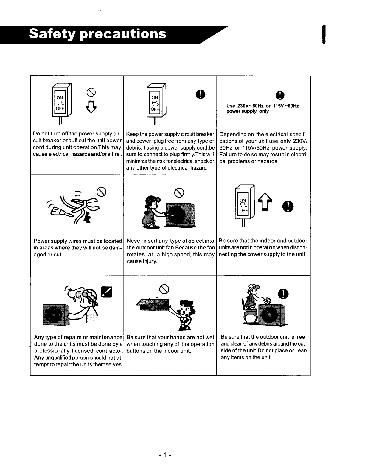
Do not turn off the
power
supply
cir-
cuit breaker orpull out the unit
power
cord during
unit operation.This
may
cause electrical hazardsand/ora fire .
o
Keep the
power
supply circuit breaker
and
power plug
free
from any type of
debris.lf using a
power
supply cord,be
sure to connect
to
plug
firmly.This will
minimize the risk for
electrical shock or
any other
type
of electrical hazard.
o
Use 230V-60H2 or 115V-60H2
power
supply only
Depending on the electrical
specifi-
cations of
your
unit,use only 230V/
60Hz or 115V/60H2
power
supply.
Failure
to do so
may result
in electri-
cal
problems
or
hazards.
Power supply wires must be located
in
areas
where
they will not be dam-
aged or cut.
Never
insert
any type of object into
the outdoor
unit
fan.Because
the fan
rotates at a
high
speed, this may
cause injury.
c
o
Be
sure that the indoor and outdoor
unitsare notin
operatbn
when
discon-
necting
the
power
supplyto the unit.
Any type
of
repairs
or maintenance
done to the units must be done
by a
professionally
I icensed
contractor
Any mqmlified
person
should not
at-
tempt
to
repairthe
units themselves,
Be sure that
your
hands
are
not wet
when touching
any of the operation
buttons on the indoor unit.
Be
sure
that the
outdoor unit is
free
and clear of any debris around the outside
of
the
unit.Do
not
place
or Lean
any items on the unit.
-1-
Page 4
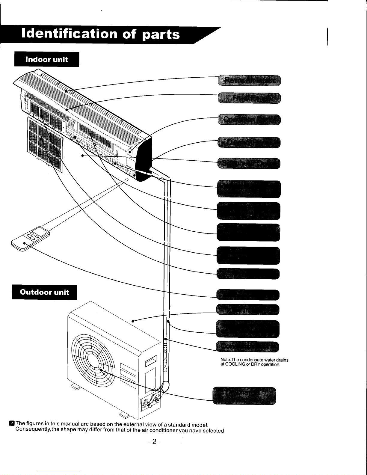
Note:The
condensate
water
drains
at
COOLING
or DRYoperation.
/The
figures
in
this manual
are
based
on
the external
view
of a standard
model.
Consequently,the
shape
may
differ
from
that
of the
air conditioner you
have
selected.
-2-
Page 5
I
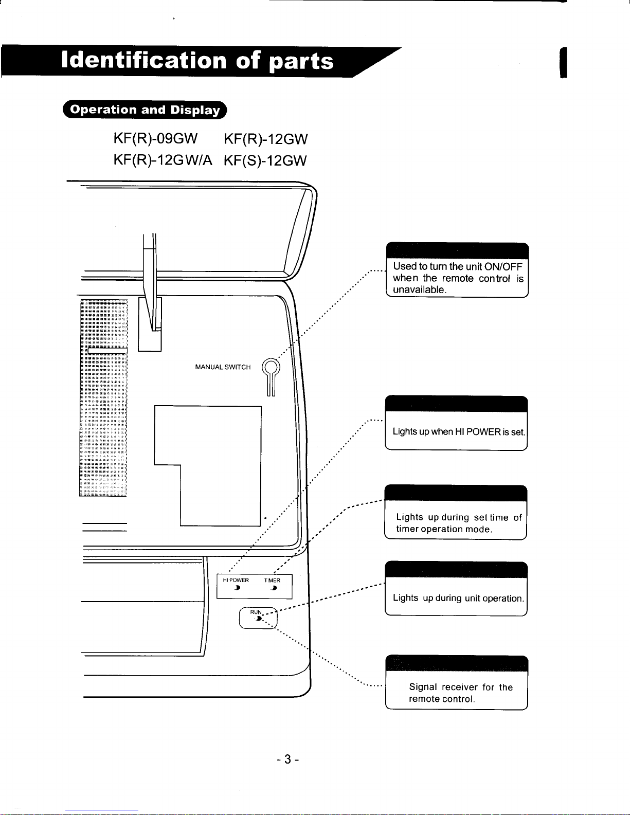
KF(R)-0ecw
KF(R)-12cWtA
KF(R)-12GW
KF(S)-12GW
HIPOWER
TIMER
,.t
Used to
turn the
unit ON/OFF
when
the remote
control is
unavailable.
Lights
up when
Hl POWER
is
set.
Lights
up during
set time
of
timer operation
mode.
Lights
up during
unit
operation.
Sigrtal
receiver
for the
remote
control.
-3-
Page 6
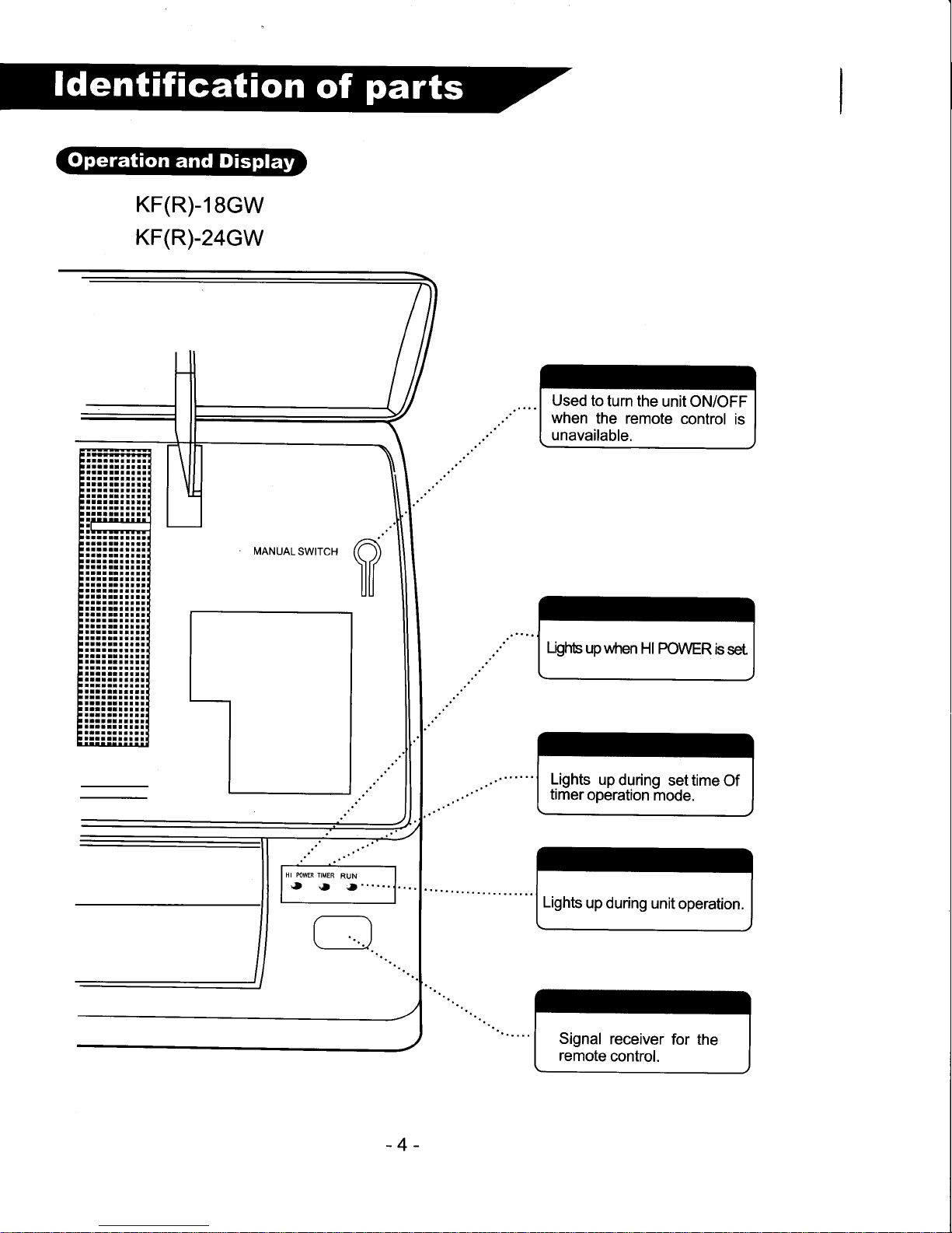
KF(R)-18cW
KF(R)-24cW
Used
to
turn the
unit ON/OFF
when
the remote
control
is
unavailable.
LQhb
up when
Hl POWER
is
set
HI MWER TIMER
RUN
.,
",
;t
"'...
G
Lights
up
during
set time
Of
timer
operation
mode.
Lights
up
during unit
operation.
Signal
receiver
for the
remote
control.
-4-
Page 7
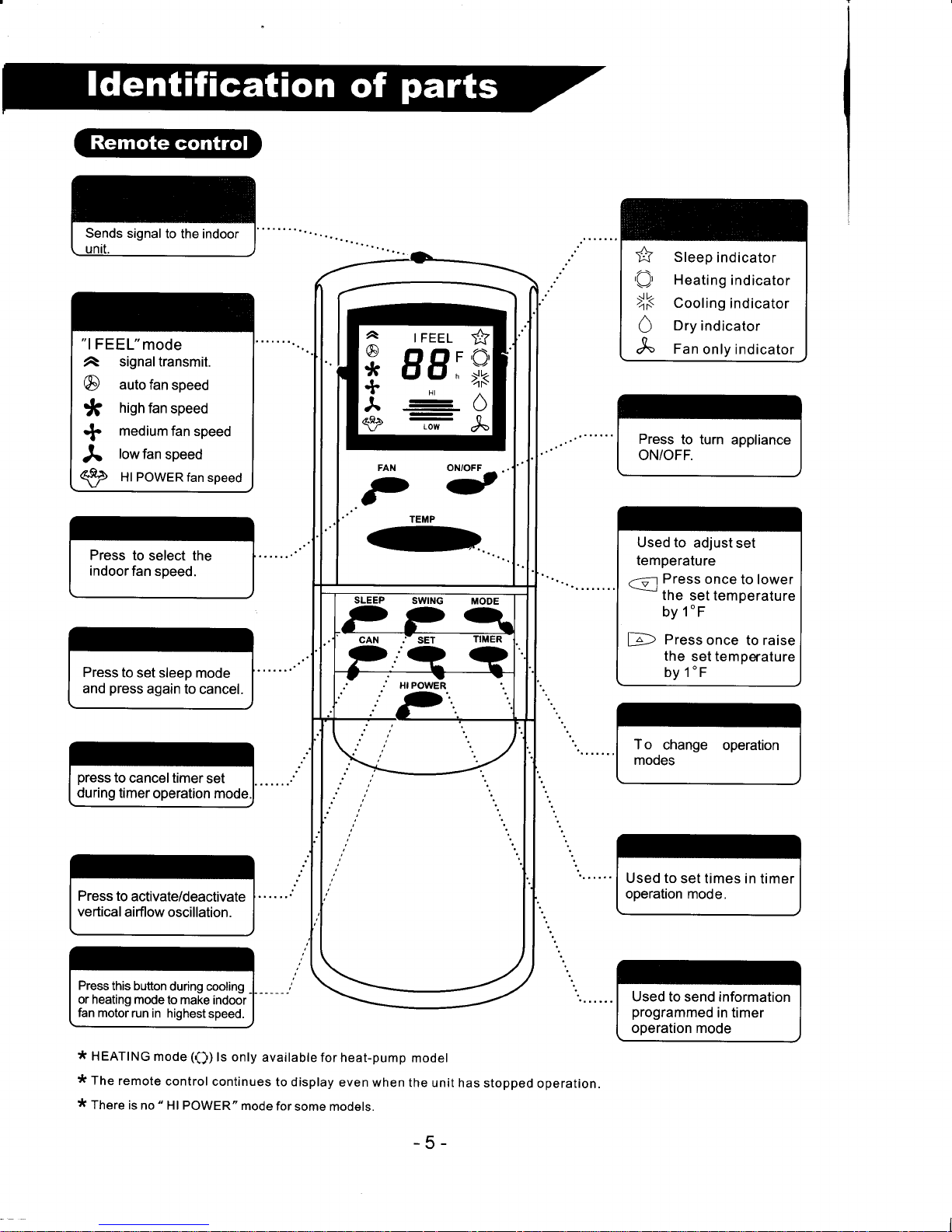
"lFEEL"mode
signal transmit.
@
auto
fan speed
*
high
fan
speed
+
medium
fan speed
A
lowfan
speed
€2
Hl PowERfan
speed
Press
to select the
indoorfan
speed.
Press
to set sleep
mode
and
press
again to
cancel.
press
to
cancel timer
set
during
timer
operation mode
Press to
activate/deactivate
vertical
airflow oscillation.
Press
this button
during cooling
or heating mode
to make
indoor
fan motor
run in highest
speed.
:t
HEATING
mode
(Q)
ls only
available
for heat-pump
model
:k
The
remote
control
continues
to display
even when
the unit
has stopped
operation.
:k
There
is no " Hl POWER"
mode for
some models.
Press
to turn
appliance
ON/OFF.
Used to
adjust
set
temperature
.-=-r
Press
once
to lower
rne
sel temperature
by
1"F
D
Press
once
to raise
the
set temperature
by 1"F
To
change
operation
mooes
Used to
set times in
timer
operation mode.
Used to send information
programmed
in timer
operation mode
\+
,C),
-.f.'
a\
Sleep
indicator
Heating
indicator
Cooling
indicator
Dry
indicator
Fan
only indicator
I FEEL
EIEIT
LfLln
+
A
@
*
+
J.
s2
+?
,f)'
>K
0
"\
SLEEP
SWING MODE
P?q
cAN ."
sET
TIMER
tDj,Q a
.7
j
", ro*l'n
t
rtP
-5-
Page 8
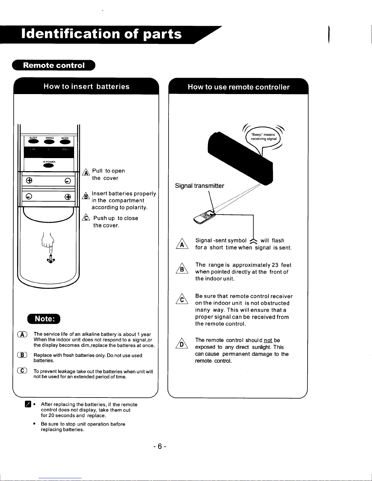
fi
Pull
to open
the
cover
6
Insert
batteries
properly
*
in
the compartment
according to
polarity.
/& Pusn up to
close
the cover.
The
service life of an
alkaline battery is
about
1
year
When the indoor
unit does not respond
to
a signal,or
the display
becomes dim,replace
the batteres
at once.
Replace
with fresh
batteries only. Do not
use used
batteries.
To
prevent
leakage
take
out the batteries when
unit
will
not be
used
for
an extended
period
of time.
fora short
timewhen
signal
The
range is
approximately 23 feet
when
pointed
directly at the front
of
the indoor
unit.
Be sure
that remote
control receiver
on
the indoor
unit
is not
obstructed
inany
way. This
will ensure that
a
proper
signal can
be
received
from
the remote
control.
The remote
control
should not be
exposed
to any direct
sunlight. This
can cause
permanent
damage to
the
remote
control.
Z.
After replacing
the
batteries, if the remote
control
does notdisplay,
take them
out
for20
seconds
and
replace.
o
Be
sure to stop
unit ooeration before
replacing
batteries.
-6-
Page 9

Each
time the
MODE
button
is
pressed,the
operation
mode
is
changed
in the
following
sequence:
HEATTNG
+cOOL|NG
+
DRy+
FANONLY->
|IFEEL/
"lFEEL"mode
is
desenbed
on
page
10
When
operating
at fan
only
mode,the
compressor
will
not operate.
*
On"FAN
ONLY" mode,only
"Hl","MED"and
"LO"
are available.
* While
on"DRY"
mode
airflow is
set
by air conditioner
automatically
"FAN"
button is ineffective
in this
case
Range
of available
set temperatures
Heatinq,
Coolinq
64'F-90
"F
DRY
room
temperature+4
-F
Press
"ON/OFF"
button,
When
the
appliance
receives
/
a signal,
a
"beep"
will
be heard.
The
RUN
indicatorwill
t
then
ughrup.
L
Open the
front
panel
to
press
the
manual
switch
to turn
on/off
the
unit when
your
remote
control
is
damaged
or
batteries
have
died.
4)
Open
the front
panetof
\)
tne indoor
unit
and
press
the
switch.
The
appliance
operates
at
"l
FEEL"mode.
The
RUN
indicator
lights
up.
@
tr"",
again
to turn
off.
The
RUN indicator
light
turns
off
and
unit shuts
down.
*
:|(
I
rn"
name
and
position
of the manual
switch may
vary from
different
modets,
but
their function
are the
same.
When
the
compressor
shuts
off or if
changing
modes
during
operation
of
the unit,
the unit may
not respond
at once
It
may be necessary
to wait
up to
3 minutes
due to
built-in
compressor
protector.
There
is a 2-5
minutes
delay
on the indoor
fan
in the
heating
mode
operation.Time
of delay
depends
on how
long
it
takes for
the indoor
coil to come
up to
a desirable
tenperarure.
@
*
+
A
B8:
Hl
.zr
/\
Each
time
the
"FAN"
button is
pressed,
the
fan
speed is
changed
in
sequence:
€
Press
once to lower
temperature
by 1
"F
D
Press
once to raise
temperature
by 1'F
-7
-
Page 10
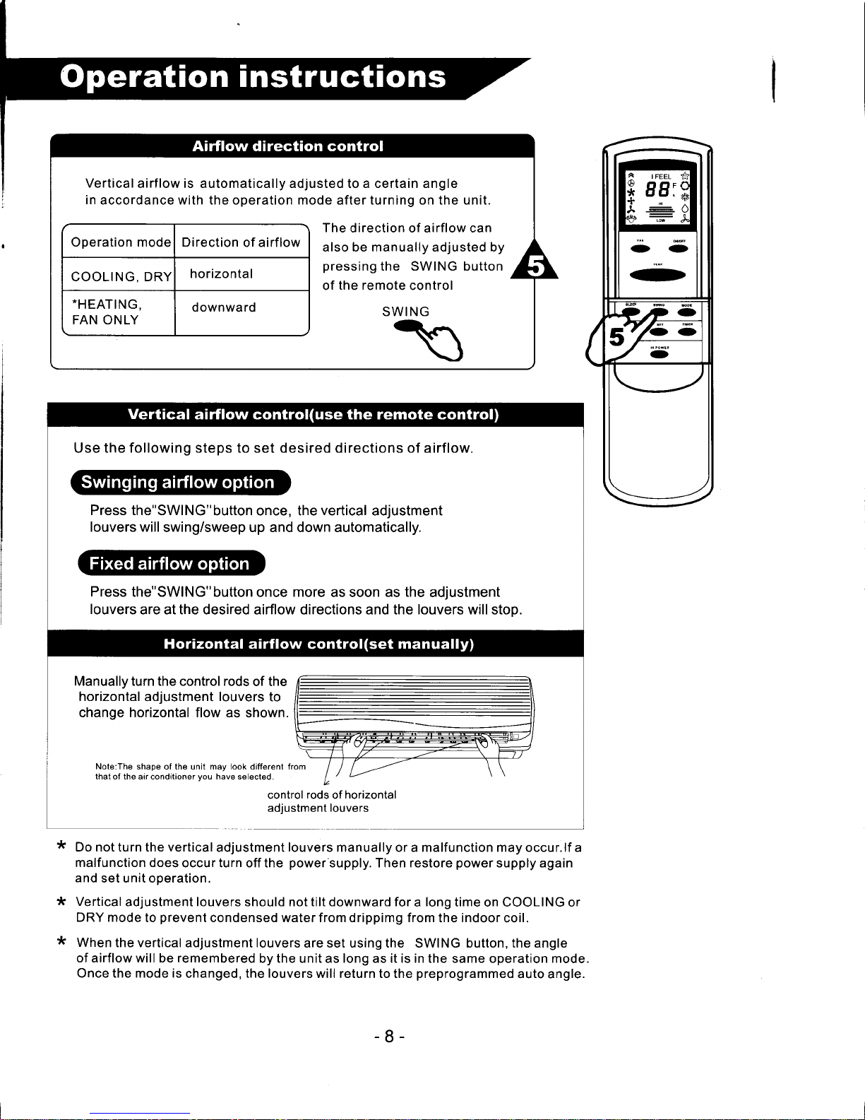
Verticalairflow
is automatically adjusted to a certain angle
in
accordance with the operation mode after turning on the unit.
Operation mode Direction
of airflow
COOLING. DRY
horizontal
-HEATING,
FAN ONLY
downward
The
direction of airflow can
also be manually adjusted by
pressing
the SWING button
of
the remote
control
Use the following steps to set desired directions of airflow.
Press the"SWlNG"button
once, the
vertical
adjustment
louvers will
swing/sweep up and down automatically.
Press
the"SWlNG"button
once
more
as soon as
the
adjustment
louvers
are at the desired airflow directions and the louvers will stop.
*
*
*
Manually turn the control rods
of the
horizontal
adjustment
louvers
to
change horizontal flow
as shown.
Note:The
shape of the unit may look different 1
that of the airconditioner
you
have selected.
control
rods
of
horizontal
adiustment
louvers
Do not turn the vertical
adjustment louvers manually or a malfunction may occur.lf a
malfunction does
occur turn off the
power
supply. Then restore
power
supply again
and
set unit operation.
Vertical
adjustment louvers should not tilt downward for a long
time on COOLING or
DRY mode
to
prevent
condensed water from drippimg from
the
indoor
coil.
When
the vertical adjustment louvers
are set using the SWING button, the angle
of airflow will be remembered
by the unit as long as it is in the same operation mode.
Once the mode is
changed, the louvers will return to the
preprogrammed
auto angle.
-8-
Page 11

Press
the
"ON/OFF"button
then
choose
the"
l
FEEL"mode
by
pressing
"MODE'
button.
The
optimum
temperature
and
airflow
volume
will
be automatically
controlled
by
the
set
indoor
temperature.
Indoor
temperature
Operation
mode
Set temperature
below
70"F
{.HEATING
73"F
7o"F-77"F
DRY
Room
temperature
a
initial
operation
77"F-82"F
COOLING
77"F
over82'F
79"F
*Not
available
for
cooling
only
models.
Slightlywarmer
Adecrease
by
4"F
can
be
set
Slightly
cooler
A rise
by €r
can
be
set
Press
twice
to lower
the
Hl
set
temp
by
2"F
EF
/\
Press
four
times
to lower
the
+
r-e-\
set
temp
bv 4'F
LOW
Press
twice
to
raise
the
Hl
set
temp
by
2"F
LOrt-
Press
four
times
to
raise
16s
Hl
set
temp
by 4"F
ffi
Uncomfortable
because
of
unsuitable
air
flow
volume.
Indoor
fan
speed
alternates
between
Hi,
Med
and
Low
each
time
this
button
is
pressed.
Uncomfortable
because
of
unsuitable
flow
direction.
SWING
(D
Press
it
once,
the verticaladjustment
louver
swings
to
change
vertical
airflow
direction.
Press
it
again,
swings
stops.
For
horizontal
airflow
direction, please
refer
to the
previous
page
for
details.
9-
Page 12

With
the
"TlMER"
funcition,
you
con
set the
unit to automatically
Start
or Stop from
30 minutes
to 24 h-ours
after
simple
programing.
For
example,
to save
energy
you
may want
to leave
the
unit off while
at work
and set the
timer
to start the
unit
one hour
before returning
home
so
a
comfortable
room
temperature
can be
achieved,
or
you
may
want
to set the
timer to
stop the
unit
late
at night.
@
As
time
passes,
the LCD
displays
the
remaining
time.
@
The
previous
set time
is stored
and
the next
set time
begins
with the
previously
set
one.
@
On-timer
and off-timer
cannot
be set at
the same
time.
CD
The room
may
not reach
your
desired
temperature
within
the
preset
time
because
of
varying
room
size and/or
outdoortemperatures.
With
the
unit off,
press
the
fir.r.
,F(
With
the
unit operating,
press
button until
desired
countdown
f'
t,
lf
the Timer
button
until
desired
hours
ard
displaved.
\_,,
countdown hours ard
disotaved
I
Set the
operating
mode,
temperature
and indoor
fan
speed first,
then
press
the
"TlMER"
button
until
"9.5h"
appears.
Z
Press
the TIMER
button,
"h"
flashes
on the LCD,
then
you
can
set the
timer.
Each
time
the button
is
pressed,
the
set time increases
byhalf
an hour
withinl0
hours
and
increases
by
one hour
beyond 1
0 hours.
The range
can be set
is 0.5 hour
to 24 hours.
Point
the
remote
control
at the
signal
receiver
of the indoor
unit,
press
the
"SET"
button
when
the letter
"h"
flashes.
A
"beeo'
will be heard:
@
Timer indicator
on the indoor
unit lights
up
@
Letter
"h"
stops flashing.
to cancelthe
set timer:
press
the
"CAN"
button,
a
"beep"
will
be
heard
and the
timer indicator
light
on the
indoor
unit will
turn
off.
-
10
Page 13

'
SLEEP
mode
can
be
set in
I FEEL,
DRy,
cooLlNG
or
HEATING
operation
modes.
'
This
function
allows a
more
comfortable
environment
for
times
of sleeping.
'
The
fan
speed
is
automatically
set at
ultra-low
speed,
which
is lower
than
low
soeed
.
The
fan
does
NOT
shut
off
during
sleep
mode.
'
Before
going
to
sleep,
press
the"slEEp"button.
The
sreep
mode
wiil
then
oe
activated.
'
when
operating
under
the
cooling
or Dry
modes,
set the
temperature
increases
by
2'F
degree
over a
2 hour
period.
lt will
then
remain
at that
temperature
until
the
unit
is
manually
turned
off
of
operation
mode
is
changed.
See
chart
below
for
more
detail.
'
when
operating
under
the
Heating
mode,
the
set
temperature
decreases
a total
of
5.5"F
degrees
over
a 3 hour
period.
lt will
then
remain
at that
temperature
until
the unit
is
manually
lurned
off
or
operation
mode is
changed.
see
chart
below
for
more
detail.
'
lt
is recommended
to
use
sLEEp
mode
together
with
oFF TIMER
to
achieve
a
more
economical
and energy-saving
operation.
SET
TEMP.
(.HEATING
mode is
not
available
for
cooling
only
models)
SET
TEMP.
t
hour
-;
t hour -l -
t
hour
-11
-
Page 14

Q
cut
off
the
powersuppty
@@
Grasp
position
"a"
and
pull
outward
to
remove
the
front
panel.
Wipe
panelwith
a
soft,
dry
cloth
Use
lukewarm
water
to
clean
if
the
unit
is
very
dirty.
Never
use
chemicals
such
as
gasoline
or
polishing
liquids
to
clean
the
unit.
Never
use
water
direcfly
onto
the
Reinstall
and
shut
the front
panel.
Reinstall
and
shut the
front
panel
by
pressing
position
"b"
downward.
The
filter
must
be
cleaned
as follows
when
the
air
conditioner
has
run
for
approximately
1 00
hours.
Stop
the
appliance
and
remove
the
air
filter.
1.Open
the
front
panel.
2.Press
the
handle
of the
filter
from
the
front.
3.
Slide
out the
filter.
O
Clean
and
reinstail
the
air
fitter.
lf
the filter
is
extremely
dirty wash
the
filter
with
a solution
of
deteroent
in lukewarm
water.
After
cleaning
allow
filter
to dry
thoroughly
out
of direct
sunlight.
For
an
air
conditioner
equipped
with
an
electrostatic
and
a
charcoal
precipitator
(optional
parts)
:
*
Do
not
clean
the
electrostatic
filter
with
water.
lt
should
be
cleaned
using
a soft,
dry
cloth.
*
The
charcoal
filter
can
be washed
using
lukewarm
water
and
a neutral
detergent.
*
lt is recommended
that
electrostatic
and
charcoal
filter
be replaced
after
8 months
of
operation,
-12-
Page 15

The following
may cause the
internal safety
device
to trip:
lf the air conditioner
runs in
"COOLING"
or
"DRY"
mode with door
or window opened
for a
long time when
relative humidity is above
80%,
dew may drip
down from the air
outlet.
*HEATING
Outdoor air
temperature
is over
75:F
Outdoor air
temperature
is
below
32'F
Room temperature
is
over
81'F
}OOLING
Outdoor air
temperature
is over
'l09'F
Room temperature
is below
70"F
DRY
Room temperature
is below 64r
o
lnstall
the indoor unit on
a wall
that will be
able to
hold its own weight,
this will ensure
that
it operates
more
quietly.
(See
page
1 7 for further
instructions about
indoor
unit
installstion.)
o
lnstall the outdoor unit
on a
location where
air
discharge and
operation
noise will not
be bothersome
to surrounding
residents.
(See
page
17 for
further
instructions
about indoor
unit installstion.)
o
Do
not
place
any obstacles
in front of
the air
discharge of
the outdoor unit.
This will cause
damage
to the compressor
and
motor and
will cause these components
to be
noisier.
(See
page
16 for further
instructions on
unit
clearances.)
The
fault
protector
device
might shut down
unit
for the following
reasons:
Stopping
the unit and
immediately restarting
it or
changing
modes
without waiting 3
minutes
for
time delay.
Plugging the
unit into the
power
source and
immediately starting
without 20 seconds
time
delay.
lf all operations
have stopped due
to the fault
protector, press"ON/OFF"button
to reset the
unit.
Set timer again
if it has been cancelled.
After using the unit
for an extended
period
of time,
the unit should be
inspected
for the
following
items:
o
Overheating of
the
power
supply
cord or
plug.
o
Abnormal operating sound
or unit
vibrations,
o
Water leaking
from the unit excessively,
o
Indoor unit cabinet becoming
electrified.
p
lf any of theses symptoms
occurs,
call a
qualified
service technician
immediately.
It is recommended
that a detailed
inspection be made
by a
qualifed
technician afbr 3
years
of
operation,
even
if the above symptoms
do not occur.
At the beginning
of
HEATING
operation,
This is to allow
the indoor coil to
raise in
there is a 2-5
minute delay on the
indoor fan
temperature
for
proper
operation.
In HEATING
operation the appliance
will
defrost
the outdoor
coil automatically
to raise
efficiency.
This
procedure
usually
lasts 2-10
minutes. During defrost
mode,the
indoor fan
stops operation.
After defrost
is complete,
it returns to the
HEATING mode automatically.
It may be difficult
to raise the
indoor temperature
when outdoor
temperature are
very low
(30'F)
this is due to
nature of heat
pumps
and their loss
in efficiency as outdoor
temperatu
res decrease.
-13-
Page 16

HEAT
PUMP
Outdoor unit
Indoor
unit
+
defrost
1l
tl
ll
heatlinc
1
coolinq
Flows of refrigerant
liquid
side
accumulator
_>
------------)
-14-
Page 17

PERFORMANCE
RATINGS
MODEL KFR.O9G/W
KFS.12G/W
KFR.12GlWKFR.18G/W
KFR.24GlWKFR.12GW(D)KFR.l8GW(D)
Capacity
Cooling
[BTU/h]
9000
12000
12400
1
8500
23100
12400 1 8500
Capacity Heating
[BTU/h]
9100
12000
1
2800
1
8800
tJzoo
1 2800+1 706 1 8800+2388
SEER
10.4
10.5
10.5
10.2
10.4
10.5
10.2
Moisture Removal[Pts/h] 2.3
2.9 2.9
3.1 5.2
2.9 3.1
Air Flow
300/370/450340t450t520
340t450t520
690/810/900
890/1100/1200
340t450t520690/810/900
Sound Rating Indoor dB
<40
<42
<42
<44
<45
<42 <44
Sound
Ratinq Outdoor dB
<5U
<52
<52
<58
<59
<52 <58
)oeratino Ranoe - Coolino [F
60 to
109 60 to 109 60 to
109 60 to 109
60 to 109
60 to 109 60 to 109
)oeratino Ranqe - Heatinq
[F
28 to 75 28 to
75 28 to 75
281o75
28 to 75 1l
to
75
2fto75
ELECTRICAL
DATA
Power Source
1 1
5-60-1
1 1
5-60-1
230/208-60-1
230/208-60-1
230/208-60-1230/208-60-1230/208-60-1
Min. Ampacity
[A]
14
15
10
15 15
10
15
Cooling
WattsAmps
810 / 7.5
1440t11.7
1230
/ 5.3
1870
/ 8.1 2323t10.1
1230/5.3
1870/8.1
Heating WattsAmps
900 / 8.0
1420t10.8
1300 / 5.7
1890 / 8.2
2375t10.3
1300w5.7A
+500W2.1A
1490/a_24
+7OOW3A
E-Aeating wattsAmps 500w2.1A
700w3A
Max
TD Fuse/Breaker
[A]
22
28
15
22
27
zz
28
REFRIGERANT LINES
Connections
Flare Flare
Flare
Flare
Flare Flare Flare
Liouid Line OD
[inl
1t4 1t4 1t4
114 3/8
1t4 114
Suction Line OD
[in]
3/8 112 1t2
uL 5/8
1t2 1t2
Max line Lenqth
lft]
49
49 49
49 49
49 49
Max Height Difference
[ft]
16 16
16
to
to
to 16
DIMENSIONS &
WEIGHTS
INDOORSECTION
KFR.O9G KFS.12G KFR.12G KFR.18G KFR.24G KFR.12G/D KFR.18G/D
WxHxDtinl
31.3x11x7.731.3x11x7.731.3x11x7.7
39x13x8
42.5x13.25x9
31.3x11x7 .739x13x8
Shiooino Weioht tlbsl
21
tt
22 23 31
LL
29
OUTDOORSECTION
KFR.O9W KFS-12W KFR.12W KFR.18W KFR.24W
KFR.12WD KFR.18WD
WxHxD[in]
25.5x19.5x12
32x21.5x1275
32x215x1215
M.5x24x1434.5x34x15
32x21.5x1215
M.5x24x14
Shipping
Weight
Ibs]
co
/J IJ
115 143
73 115
Refriqerant Charqe
ilbsl
2.1
2.4
2.8 4.5
3.3 2.8
Specifications are subject
to
change
without
prior
notice. Visit our website - www.soleusair.com
Copyright
2003
Soleus
International Inc.
15
Page 18

fN
\!
Distance
from
ceiling
should
be
2 in
Distance
from
the
wall
should
be 2 in
fl
U
air intake
distance
from
the wall
should
be 10
in
Z
.
The
above
diagram
illustrates
atypical
unit.
\
The
unit
you
purchased
may
vary
in
appearance.
o
The
unit
must
be
installed
in
accordance
with
state
ard
local
codes.
-16-
Page 19

---
Indoor unit installation location:
.
Locate indoor
unit so that there is no obstructions near the
supply air or return air
outlets.
o
The wall that
the
indoor
unit hangs on must
be
free from internal
obstructions to
facilitate a clear hole for the refrigeration
lines and condensate line to
go
through.
o
Proper clearances must
be maintained to ceilings and walls
per
instructions
on
page
16.
o
Easy access must
be maintained for removal of the air filter.
r
Indoor unit and remote
control must be at least 3 feet from televisions, radios,
etc.
r
Indoor
unit and
remote
control must be kept
out of direct sunlight and/or fluorescent
lighting.
o
The
wall that the indoor unit hangs
on
must
strong enough to bear the weight of the
unit to ensure
quieter
operation.
Outdoor unit
Outdoor unit installation location:
o
Outdoor unit location must be well ventilated. Avoid installing
where any type of flammable
gas
could
leak.
tr-J--
o
Proper
clearances must be maintained
per
instructions
on
page
16.
ll =E I
r
The maximum length for refrigeration
lines is 49 ft. For refrigeraton lines
exceeding 23ft. an
ll d: I
additional. 75
pounds
must
be added
per
3.5 feet.
(al]
ll ?E I
o
The
Maximum height between indoor
and outdoor units
in
25ft. lf the
outdoor unit
is located
l/ | I ll H fr |
abovetheindoorunitmorethan4ft.,asuctionlineoiltrapmustbeinstalled.
ll I I Il
€g
I
r
The
outdoor unit
must not
be located in environments that have high
contents of acidic
K-
j
n\ ll J
substances, vulcanized
gasses,
or high salt contents in the air.
Indoor
r;itffitd;i;it
o
The
outdoor unit must not be located near locations where
dirt. mud. or debris
can be caked
Suction
line
oil trap
onto
the outdoor coil or unit.
o
The foundation
that the outdoor unit
sits on
must
be solid and sound so as to decrease noise
vibration.
.
No obstructions should be
olaced around the outdoor unit.
Installation Diagram
lndoor unit
9n
]N
vE
oo
co
6(l)
.92
o)
1. Installing
the mounting
plate
o
Hold mounting
plate
on the wall where unit will be located.
Using a level or
plumb
line, ensure that the
plate
is
level. Once the
plate
is level, mark holes
that
will
be
used to hold olate on the wall.
o
Remove
plate
and
drill
marked
hole at a depth of 1.75 inches.
.
Insert the screw
plugs
into the holes
and affix the mounting
plate
using the tapping
screws.
o
Once
mounting
plate
is securely fastened to the wall, then locate
an area on the wall for the
access
hole for
the
refrigeration
line/condensate line/wiring
bundle,
E
2. Access hole for refrigeration
lines/condensate drain line/wiring
bundle.
E
r
These directions must
be
followed
at least for the condensate
drain
line.
There must
be
rear
access for the condensate
drain
line
to drain
properly
from the unit.
r
Decide
on a location for the access hole
according to the location of the unit.
r
Drill a 2.5 inch hloe, making
sure that there is a tilt downward of
a 114
inch. This will ensure that
proper
drainage is maintained for the
condensate drain line.
(lf you
are not using rear access for the refrigeration
lines and wiring, the hole
does
not
need to be as large.)
o
lt is recommended that a wall
sleeve of some sort
(i.e.
PVC
pipe)
be used to keep the hole neat and tidy.
Note: The shape
of
y@r
mnting
plate
may
be difieront from
the one above. but installationretfbd is similar
Pipe
length is
49 ft Max.
3o
fN
"'E
oo
co
6(l)
-92
a)
Dropping line
17
Page 20

Saw the cut-out access off
along the side of the casing
3. Indoor unit
refrigeration line installation
o
The refrigeration
lines
and
wiring
can be
routed
to the outdoor unit
in a number of ways
(left
or right from the back of the
unit), by using the cut-out access
pieces
on the casing of
the
unit.
r
Bend the refrigeration
lines
carefully to the
required
position
in
order
to
be aligned
with the
drilled
hole.
When installing the refngeration lines
at
the directions 1
,2
or 4,
saw the corresponding cut-out
piece
off the indoor unit casing.
e
Afterconnecting refrigeraton lines
(see
directions below), install the condensate drain line
(see page
21+24for detailed
instructions on connecting condensate drain line). Then connect all wiring
(see
pages
25-27
for
detailed
instructions
on
wiring).After all connections are
made,
bundle the
refrigeration lines, wiring,
and
condensate drain line together using a
thermal insulation and vinyl/duct tape
Refrigeration lines insulation:
o
lt is important that
both
the liquid
and suction
refrigeration lines are individuallv insulated to ensure
that they do no sweat and also to maintain
proper
unit
capacities. This is necessary since the refrigeration is
metered from
the outdoor unit and
will
produce
condensation on both
refrigeration
lines if not
proper
insulated.
power
Refrigeration lines/Condensate drain line/wiring bundle thermal insulation:
o
Place
the condensate drain
line
under the refrigeration
lines.
r
lnsulation material should be a
polythene
foam that is approximately a 114
inch wall thickness.
r
Condensate drain
line
should have a downward slooe at all times to ensure
proper
drainage. Do not allow the drain line to
be
twisted, horizontal or the
defrost cable(for heat-pump)
end of the
line
be
immersed in water. lf
an extension is added to the drain
line, make
sure that it is also
properly
insulated.
Connection of
refrigeration
lines:
o
Do not
use contaminated or damaged copper tubing
for refrigeration lines.
lf any of the tubing,
evaporator or condenser coils have been exposed to the air for more that 15 seconds, it is
@@-
important
that
they
are
vacuumed
and
purged
with
field-supplied refrigerant.
Do
not removeimportant
that
they
are
vacuumed
and
purged
with
field-supplied refrigerant.
Do
not remove
...+fq-
plastic
or
rubber
plugs
and brass
nuts
from the valves,
fittings,
tubing, or coils until they are
-itA
t-
ready to
be connected.
\$\ \
Jse
proper
tubing cutters to cut the refrigeration lines, advancing the blade of the tubing cutters
slowly. Extra force or improper cutting will
cause
tubing
distortion
and
also extra burrinq.
\
oncerefrigerationtubesarecut,remoVeburrsfromcutedgeswitharemover.Thiswi||avoid_b.
unevenness on
the flare faces, which
could cause a
gas
lelk. Hold the ends of the
pipes
+A
downward to
prevent
metal from
going
into the tubes.
-r
l(
lnsert the flare nuts, mounted
on the connection ends of both the indoor and outdoor units onto
./_€l
l
the ends of the copper tubing.
/o
/
,A
The length of the
pipe protruding
from the face
of
the flare
die
is determined
by
the
particular
flaring tool that will be
plastic
or
rubber
plugs
and brass
nuts
from the valves,
fittings,
tubing, or coils until they are
readv
to be connected
.
Use
proper
tubing cutters to cut the refrigeration lines, advancing the blade of the tubing cutters
slowly. Extra force or improper cutting will
cause
tubing
distortion
and
also extra burring
o
Once
refrigeration
tubes are cut,
remove
burrs from cut edqes with a remover. This will avoid
used.
r
Fix
the
pipe
firmly
on the flare die. Match the centers of both the flare die and the flaring
punch,
and then tighten the
flaring
punch
fully.
Once flaring is
complete, connection of the tubing is
ready. Align
the center of the tubing and tighten the flare nuts
using a torque wrench.
wrapped with
vinyl
or duct type
Thermal insulation
thermal insulation
-18-
Page 21

Properly
connect the
electrichl wiring
between
the indoor
and outdoor
unit
as shown below
Heat
pump
THIS
APPLIANCE
MUST BE
GROUNDED.
IMPORTANT:
The figures
shown
below are for information
purposes
only.
Make
sure that local
andior national
codes and regulations
are complied
with when
making
connections.
4 .
lnterconnecting
wires
(1)
Remove
the indoor
terminal
cover:
Open the front
panel
and remove
the indoor
terminal board
cover.
Jt
D-sstrygp__-O
5. Conduit
fittings
Outdoor
unit
ConduitA--Jor
P@er
Inter Cffmcting tundudm
(2)
Supply wiring,control
wiring
and defrost
cable connection.
defrost wire
Heat
pump
connector
Defrost
cable
Indoor
unit
terminal block
Power
supply
Conduit
Connector
Turning the
Conduit Connector
clockwise
can loosen it from
conduit.
Cabinet
Control wiring
-
19
-
Page 22

a
a
la
6. Installation
of conduit
bracket
rhe
shape
of conduit bracket is
shown
Put the
conductors through
the
Conduit
and Connector. Tighten
the
Conduit Connector
to the
conduit.
Put the
conductors through
the Connector
and the
Condult Bracket. Tighten
the
Connector
Nut to the
Connector.
Turn the locknut
counterclockwise
to tighten
the locknut.
Mounting
the Indoor
unit tothe Mounting
Plate:
o
Hook
the indoor
unit onto the
upper
portion
of the mounting
plate
by
connecting the hooks
at the
rear top
of the indoor
unit with the upper
edge of the mounting
plate.
r
To
ensure that
the hooks are
properly
seated
on the mounting
plate,
check if the unit
can slide
by moving
it to the left
and right. lf the
unit moves, it
is not
properly
seated.
o
A unit
support
plate
in the mounting
plate
can be used if
the unit is
on a slanted wall
and can
also be used
to ease the connection
of the refrigeration
lines.
o
After connecting
the refrigeration
lines, remove
suppopt
plate
and
afiix the bottom
of the mounting
plate
to the wall with
screws.
Support
plate
Connection
of condensate
drain
extension
line:
Place
glue
on the
end of the
drain
line
extension
end.
Fully insert
the end of the
drain line to
the extension line.
Make
sure it is
properly
inserted
to no less than
3/8 of an inch
so that water
does not leak
from the hose.
Glue
<
3i8 inch
Locknut
(Turn
the locknut
counterclockwise
to
Conduit
Connector Connector
Nut
-20-
Page 23

FIGURE
currNG coPPERrueea*@
#@
FIGURE
FIGURE
TUBE
A(mm)
lnch
mm
lmoerial Rioid
1t4" 6.35
1a
0.7
3i8"
9.52
t-o
1.0
1t2"
12.70 1.9 1.3
5/8" 15.88
2.2
1.7
3t4"
19.05
2.5 2.0
1. lnstall
the outdoor unit
o
Outdoor unit
must be mounted on
a solid,
level foundation.
lf
possible,
affix unit using bolts
to the
foundation.
o
lf installing on a
wall
or
structure, be sure
that construction
of the wall or structure
can support the
weight of the unit
and
that
consideration
is
given
to the integrity of
the construction. Since
the unit can
vibrate during operation,movement
of
sound of
the unit should be
considered
when installing the unit.
o
Since
the unit discharges
air during operation,
plants
or other
obstruction should
be free and clear
of the unit
to
ensure
proper
operation.
.
Owners
should be
advised to avoid
lawn mowers or other
machinery discharge
toward the unit,
as debris can damage
the finned coil surfaces and reduce effciency
of the unit.
2. Outdoor
unit
refrigeration line connection
o
Remove
the valve caps at
the outdoor unit
where refrigeration
tubing will be connected.
o
Connect
the refrigeration tubing
using flaring techniques
described earlier
in the
indoor unit installation.
Be sure to use
required torque.
f
Atteniton
o
A baffle
is needed when
installation is in locations
near the sea or areas
with strong
winds.
.
Be sure that unit
airflow is not obstructed
in any
way
or
that reciculation
of discharge air
does not occur.
FLARE JOINT
FLARED
TUBE
\+t
rurorEItr
\\
INDOOR
PIPING
|
/'^
"u'
G4 nth
// ))tr/
V..
q7
\roReuewReuc*
PIPE SIZE(mm/in) TORQUE(Nm)
6.35(1/4)
18
9.53(3/8)
42
12.7(12\
55
1 5.88(5/8)
65
1e.05(3/4) 78
END
DIPPED
INTO
WATER
FIGURE I
nll rlll
*ft,,^-JIl
ll"o^'^ofl
@@
CORRECT WRONG
@
WRONG
-21 -
Page 24

3. Wiring
connection
Remove the
electrical cover of outdoor unit
(1
screw).
Connect
wires
as shown below in the illustrations.
Heat Pump
Connect to Power Supply
Power
supply inter connecting
conductors
(in
conduit
A)
(to
the indoor
unit)
Control inter connecting
conductors
(in
conduit
B)
(to
the indoor
unit)
The
conduit should not
be
loosened
after being fixed, otherwise, it may
cause abnormal noise when
the
unit is running.
Number 14 wire
should be used for KFR-18GW.
Number 12wire
should be
used
for KFR-24GW.
KFR-18GW/(D)
Number 14 wire
should be used for KFR-09GW. KFS-12GW.
KFR-12GW/(D)
Number 16
wire should be used for KFR-12GW.
Outdoor unit terminal
block
-22-
Page 25

System
Start
Up
and Charge
Adjustment
Procedures
Additional
Charge
Needed
for
Refrigeration
lines over
15 feet
Liquid
Line O.D.(lnches)
Additional
R-22
(ozlft)
1t4
.22
3/8
.58
Properly
check
refrigeration
tubes
and connections
for any
leaks
prior
to system
start up
procedures.
NOTE:
A is the low-pressure
valve
B is the
high-pressure
valve
C and
D are the
joints
of
connecting
pipes
of
indoor unit.
The outdoor
unit
is
supplied
with a R-22
charge sufficient
for 15 feet of
refrigeration
tubing.
The outdoor
unit's
liouid and suction
valves
are closed
to contain
the charge
within
the
unit.
The recommended
procedures
for charge
adjustments
are
as follows:
\
Vacuum
pump
il'6-l-
,ffi)
1. After connecting
the
refrigeration
tubing to
the indoor
and outdoor
units. connect
a
Low-pressure
vacuum
pump
to the refrigeration
valve service
ports.
2. Evacuate
through
the liquid
and suction
valve service
ports
to 500
microns or
less for a
minimum
of
30 minutes' Close
the valves
to the
pump
and
monitor
the vacuum
for
15 minutes.
The vacuum
should not
rise above
800 microns.
3.
lf a vacuum
of 500
microns cannot
be obtained,
or
if it rises above
800
microns over
the 15
minute
period,
discontinue
evacuation,
pressurize
the system
with
nitrogen and
look
for leaks. Repair
any
leaks that are
found and
repeat step
2.
4.
Close
the
valves to
the vacuum
pump,
tufn the
pump
off, and
disconnect
it from
the refrigerant
valve
service
ports.
Open
the liquid
and suction
service
valves
fully, releasing
the
R-22 into the system.
Connect
the service
gauges
to
the refrigerant
Valve service
ports.
5. Set
the
indoor remote
control
to cool
mode and ensure
proper
operation.
Allow unit
to run
for a
period
of 10
minutes to
allow system
pressures
to stabilize.
-
Make sure
that
proper pressures
are observed.
'
Check
proper
temperatures
in space,
to ensure
temperatures
match
those on
remote control.
-
Check condensate
drain
hose
for
proper
drainage.
'
Check
for any abnormal
vibration
noises
and correct
as
needed.
-
Check
for any signs
of refrigerant
leakage.
6. Set
the indoor
remote control
to
heat mode
and ensure
proper
operation.
Allow unit to
run for a
period
of
10 minutes
to allow system
pressures
to stabilize.
Allow same
checkouts
as cool
mode'
-tSonHg'
Lorod'
Filling
hose
+
Hi rod
Filling hose
Checking
points
of outdoor unit
I I
Connecting
PiPe
nut
|r'
-%) Limit brocx
/7\#^ / ...
l9]-JJ.(@-,
rvarvecao
l\A
Valve body
I
t{/
Valve rod
Manifold
valve
-23-
Page 26

HOW
TO
INSTALL
DRAIN
ACCESSORIES
There
will
be sone water
dripping
from
the
condenser
when
the heat
pump
is
working
during
the heating
mode.
Two
drain
caps,
a drain
elbow with
rubber
collar
and a
plastic
hose
(5/8"
x
6") are
supplied for
user if
choice.
INSTALLATION
STEPS
(1
)
Observe the
drainage
flow
of the
three drain
holes
on the
base while
pouring
water into
the
condensing
unit
evenly
around
the condenser. (Figure
1)
(2)
Connect
the drain
elbow
and the
plastic
hose.
(Figure
2)
(3)
Insert
the
drain
elbow
connected
with the
drain hose
into
the hole
which
has
the largest
drainage
flow
and
rohte
it
to the wall
side
of the
building in
order to make
the
drainage
flow
against
the wall.
The
other two holes
of the base
should
be
plugged
by
using the
two
drain caps.(Figure)
NOTE:
lf
the drain
hole inserted
with
the
drain elbow
is not
at the
desired location,
adjust the
level
of the
condensing
uint
slightly,
and then reinstall
the accessories
according
to the
above steps.
1
Look
2
Drain
cap
Install
Draln
e!!ry---L
-=
'Plastic
hose
o
x
6u)
0
-24-
Page 27

ELK'IRICAL SCHN,,IATIC
DIAGRAM OF TIIE INMOR
(NN
KFR{9/12G
KFS.12G
E
lwl
tot
-l';
-{;I
{,;t
-Ll
--tE
{O
ELECTRICAL SCHEMATIC DIAGMM OTTHE
INDOOR UNIT
Fl
FI
td
FI
-ill
-tt
+t
-T;1
--t!
----.,4
v
OUTDOOR
UNIT
t-l
rrt
H
i
3Ll
J,l
{,;t
{;t
-E
A
OIJTDOOR
UNIT
-25-
Page 28

ELECTRICAL
SCHET4{TIC DTAGMM OF TI{E IIIDOOR
TNIT
KFR.12G/D
ELECIRICAL SCHI\{ATIC
DT{GMM OF THE INDOOR
UNIT
E
F]
[+n
-lLl
{t
T-'l
--,Ll
-fit
{i-]
--.-.-ai\
oIJ.]W)RUNIT
*uo
\J/*
(9'u'.**
s ,__,-\
0\tRicm mmECI
rT
Dattt
a\\cYEL^r
ELECTRICAL
SCHEMATIC DIAGRAM
OF
THE
CO{DENSINC
L]NIT
POTER SUPPLY
CORD
1
l0 120V-60H2
lr
KFR.OgW
KFS-12W
-26-
Page 29

ELECTRICAL
SCHEMATIC
DIACRAM
0F TI{E C0.IDENSING IJNIT
PO{ER
SUPPLY
208-230V'60H2
-l
I
---l-
KFR-12W
KFR-12w/D
REVERS ING VAI\T
CAPACITOR
ELECTRICAL
SCHEMATIC DIAGRAM OF THE CONDENSING
UNIT
REVERS INC
VALVE
CAPACITOR
KFR.ISW
KFR-18w/D
ELECTRICAL
SCHEMATIC DIAGRAI\,{ OF THE CONDENSING INIT
-27 -
Page 30

A
wnRNrNG
Q
use coppER wtRES
oNLy FoR
powER
supply.
Q
wnnuNG:RrsK
oF ELECTRTc
sHocK,
cAN cAUSE
TNJURv
oR DEATH.
DISCONNECT
ALL ELECTRIC
POWER
SUPPLIES
BEFORE
SERVICING.
Q
ountruc
coNNEcroN
oF
THE
REFRTcERATToN
TUBES,
rF
EXcESSTvE
TORQUE
IS
IMPOSED
ON FLARE NUTS,
SERVICE VALVE
ON
DISCHARGE
LINE MAY
BE DAMAGED.
WHEN
TIGHTENING
FLARE
NUTS
OR NARROW
PIPE,
TORQUE
SHOULD BE ADJUSTED
BETWEEN
13.7-18.6N.M
(140-190GF.CM).
O
oo
Nor
pur
tNDooR
uNtr tN LocATtoNS
wHERE
tr MAy
cET
wET.
Q
rlecrRtcAl
INSTALLATToN
MUST BE
rN ACcoRDANCE
wtrH LocAL
AND
STATE ELECTRICAL
CODES.
Q
rHe tNSTALLATIoN
oF
THESE
uNrrs REQUTRES
euALtFtED
pERSoNNEL.
Q
crmFrED
(AppRovED)
powER
supply
coNDUcroRS
MUST
BE
usED.
O
nru
INDEPENDENT
BRANcH
cIRCUIT BREAKER
MUST
BE
USED.
Q
unxnltuM
TNTER
coNNEclNG wtRE
LENGTH
sHouLD
Nor
EXcEED
11.3M
(37FT.)
Q
ne
rntcERATtNG
ptpE
LENGTH
MUST BE
LtMtrED
BETWEEN
4-10M
(13FT-33FT.)rF
THE
LENGTH EXCEEDS
7.62M(25FT.),
THE
COOLTNG
(oR
HEATTNG)
CApACtTy
MAy
BECOME tMpAtRED.
Q
otrrrRENcE
tN HETcHT
BETWEEN
rNDooR
AND
ourDooR
uNlr
sHouLD
NOT
EXCEED
7M(26FT.).
-28-
Page 31

lf after checking
the
following conditions
the unit
still does
not operate,
call a
qualified
service
technican.
o
Fault trip or
fuse is blown.
o
Fault device
trips to
protect
the appliance.
o
Batteries
in the remote control
are
dead.
o
Plug is
not
properly plugged
into outlet.
o
ls the air
filter dirty?
o
Are the intakes and outlets
of
the indoor
or outdoor
units blocked?
o
ls
the
temperature
set
properly?
-
,t4#
kl 1l)
lf strong
interference
(from
excessive
static
electricity discharge,
power
supply
voltage
abnormality)
is
present,
operation
may be
abnormal.
lf this occurs
,
disconnect
from the
power
supply
and connect
back
2-3
seconds
la
Changing
modes during
operation,
must wait for
3 minute delay.
Does
notoperate
-
(ffi')l
immediatery
Gffi
Odors may come
from another
source
such as
furniture, cigarettes,
etc.
These odors
may remain on
the indoor
coil,
or filter
which may
require cleaning.
o
Caused
by
the flow of
refrigerant
in the
air conditioner.
o
Sound
from defrost
mode in
heating mode.
(Note:For
some
model with a compressor
indicator
(red),
it lights up
during
defrosting.)
o
The sound
may
be
generated
by the expansion
or contraction
of
the front
plastic panel
due
to
change
of
temperature.
a)-
lw
tt t
ro-
6)
Mist appears
when the
room air becomes
very cold because
of cool air
discharged
from
indoor unit during
"COOL|NG"
or
"DRY"
operation
mode.
-29
-
Page 32

RUN
light
blinks
Defect
What
to
check
l time
Abnormality
of room
temperature
sensor.
o
Open
circuit
or
short
circuit
of room
temperature
sensor.
o
Incorrect
connection
of
the
sensor.
2
times
Abnormality
of
defrost
sensor.
o
Open
circuit
or short
circuit
of defrost
sensor.
o
Incorrect
connection
of the
sensor.
3 times
Abnormality
of
indoor
fan
motor.
a
o
Indoor
fan
motor
is
defective.
Bad
connection
to motor.
4 times
Abnormality
of
outdoor
unit.
o
Compressor
is
defective.
o
Refrigerant
is low.
r
Capacitor
is
defective.
Continuous
blink
No
defect-unit
in
defrost
mode.
-30-
Page 33

LIMITED
WARRANry
Soleus
International Inc.
warrantsthe accompanying
Hitachi RAS09,
Hitachi RAS12, and Soleus
Air KFR and KFS series
ductless mini split air conditioner
/ heat
pump
to
be
free of defects
in
material andworkmanshipforthe
applications
specified in its operation
instruction
for
the
period
of labor and
parts
specified
below.
LABOR
PARTS
30
DAYS
(COMPRESSOR)
5
YEARS FOR
COMPRESSOR
1 YEAR FOR
OTHER
COMPONENTS
This
warranty shall not apply to broken
or
marred
cabinets,
accessories,
knobs, filters or
routine
maintenance.
This warranty does
not
apply
to uncrating, setup,
installation, removal of
the
product
for repair or reinstallation of
the
product
after
repair..
This
wananty
does
not apply to
repairs or replacements
necessitated by any cause
beyond the
control
of Soleus
International including,
but not
limited
to, any
malfunction, defect or
failure
caused by or
resulting from unauthorized
service or
parts,
improper maintenance,
operation
contrary
to
furnished
instructions, shipping
or transit accidents,
modification or
repair by the user,
abuse,
misuse, neglect, accident,
incorrect
power
line voltage, fire, flood or otherActs of
God, or
normalwere and tear.
Warranty service
must
be
performed
by a
qualified
HVAC contractor. Soleus
maintains a
centralized
service
network to
provide parts
and
assist in resolving service
problems
if
dfficulties
are encountered. Soleus
agrees to
provide
service
information, sell repair
parts
and
reimburse
the dealer / servicer
for
parts
and servi@s
in accordance
with Soleus International's
Policies and
Procedures.
SOLEUS
INTERNATIONAL MAINTAINS
THAT ALL
WARRANTIES, INCLUDING
IMPLIED
WARRANTY OR
MERCHANTABILITY
ARE LIMITED
TO THE TERMS AND CONDITIONS
SPECIFIED
ABOVE. SOLEUS
INTERNATIONAL
DISCLAIMS ANY LIBILITY
FOR
CONSEQUENTIAL
OR
INCIDENTAL
DAMAGES AND IN
NO EVENT
SHALL
SOLEUS
INTERNATIONAL INC.'S
LIABILITY EXCEED
THE RETAIL VALUE OF
THE AIR
CONDITIONER.
FOR
CUSTOMER
SERVICES.
WARRANTY CLAIM
AND PARTS PURCHASING, CONTACT:
Soleus lnternational
Inc.
Tel:
1-888-8
Soleus
Monday Through
Friday, 9:00 AM to 5:00
PM, PST
Email: Contact@soleusair.com
Website:
www.soleusair.com
-31 -
 Loading...