

Page 1
HTB-75 N
HTB-90 N
HTB-150 N
Manual de instalación e instrucciones de uso
Installation manual and operating instructions
Notice d’installation et d’utilisation
Manual de instalação e instruções de uso
Manuale d’installazione e istruzioni
Montageanleitung und gebrauchsanweisung
Инструкция по монтажу и эксплуатации
Page 2
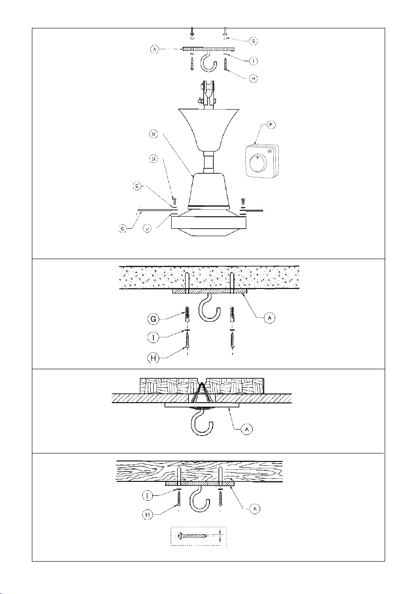
Fig 1
Fig 2
0
1
2
3
Fig 3
Fig 4
2
Page 3
OK NO OK
Fig 5
Fig 6
Fig 7
3
Page 4
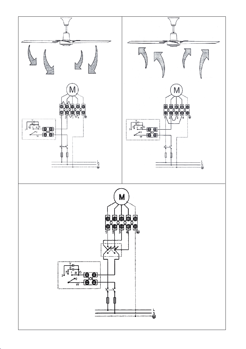
Fig 8 A
Fig 8 B
Fig 9
4
Page 5

ESPAÑOL
MANUAL DE INSTALACIÓN E INSTRUCCIONES DE USO
Aviso: Lea todas las instrucciones detenidamente para asegurar una operación e instalación
segura del equipo.
Ni el fabricante ni el agente/distribuidor ni el comercio donde se compró este producto ten-
drán responsabilidad alguna por daños o perdidas ocasionadas por la compra y/o instalación
de este producto.
ADVERTENCIAS DE SEGURIDAD
Para asegurar una instalación segura de su ventilador de techo, lea las siguientes normas de seguridad general antes de iniciar la instalación.
1.- La instalación del ventilador debe llevarse a cabo por un instalador cualificado.
2.- Para asegurar una instalación perfecta, lea el manual de instrucciones y
estudie los diagramas antes de iniciar la instalación.
3.- Todas las conexiones eléctricas deben conformar con las normas vigentes tanto locales como nacionales. Si no está familiarizado con las instalaciones eléctricas, solicite los servicios de un instalador cualificado.
Antes de conectar el aparato, verifique que la tensión de alimentación y
4.la frecuencia, coincide con los datos técnicos indicados
características.
5.- Estos aparatos deberán conectarse a una toma de tierra.
6.- Los medios de desconexión que deben ser incorporados a la instalación fija,
para su desconexión omnipolar de la red de alimentación, deben presentar
una separación de contactos de como mínimo de 3 mm en todos los polos.
7.- Asegure que el lugar de instalación deje libre la rotación de la hélice del
ventilador. La hélice debe estar como mínimo a 2.30 m por encima del
suelo una vez instalado.
8.- Si va a instalar más de un ventilador asegúrese de no mezclar las palas
de las hélices de distintos ventiladores, aunque sean del mismo modelo.
9.- Antes de empezar a manipular la red eléctrica, quite los fusibles o desconecte el interruptor principal del suministr
o eléctrico.
10.- Después de instalar el ventilador, asegúrese de que todas las fijaciones
estén correctas para evitar la caída del ventilador.
11.- Nunca inserte objetos entre las
palas de la hélice mientras el ventilador
esté en movimiento.
12.- Este aparato pueden utilizarlo niños con edad de 8 años y superior y per-
sonas con capacidades físicas, sensoriales o mentales reducidas o falta de
experiencia y conocimiento, si se les ha dado la supervisión o formación
apropiadas respecto al uso del aparato de una manera segura y comprenden los peligros que implica. Los niños no deben jugar con el aparato.
13.- La limpieza y el mantenimiento a realizar por el usuario no deben reali-
zarlos los niños sin supervisión.
en la placa de
5
Page 6

14.- Cada ventilador ira gobernado por su regulador. No se puede utilizar un
regulador para gobernar más de un ventilador.
NOTA IMPORTANTE: Las instrucciones y mecanismos de seguridad que aparecen en este manual
de instrucciones no pretenden cubrir todas las posibles situaciones y condiciones que puedan ocurrir.
Debe entenderse que sentido común, precaución y cuidado son factores que no se puede incluir
dentro del producto. Estos factores lo prestan las personas que mantienen y operan el ventilador.
INSTRUCCIONES DE DESEMBALAJE
Antes de montar el ventilador de techo, saque las piezas de dentro del embalaje y compruebe que
todos los componentes de la lista estén incluidos. (Fig.1)
A- Soporte gancho. (1 Unidad)
B- Conjunto motor más soporte. (1 Unidad)
C- Palas. (3 Unidades)
D- Tornillo fijación palas. (6 Unidades)
E- Arandela de seguridad. (6 Unidades)
F- Conjunto regulador de velocidad. (1 Unidad)
G- Tacos. (2 Unidades)
H- Tornillos de fijación. (2 Unidades)
I- Arandela de seguridad. (2 Unidades)
J- Protección de tela. (3 Unidades)
Manual de instrucciones.
5
INSTRUCCIONES DE INSTALACIÓN
FIJACION DEL VENTILADOR DE TECHO
NOTA IMPORTANTE: Siga cada una de las indicaciones que se dan a continuación, de esta forma
evitará la posibilidad de provocar un accidente por caída del aparato que podría llegar a derivar en
responsabilidades penales para el instalador.
Asegúrese de que la distancia desde la parte más baja del ventilador, una vez instalado, hasta el
suelo, sea como mínimo de 2.30 metros.
Compruebe que el punto de fijación del aparato sea capaz de soportar el peso del ventilador en
movimiento según el modelo adquirido
(HTB 75 N / HTB 90 N mínimo 25 Kg. - HTB 150 N mínimo 40 Kg) .
Fijación en un techo de hormigón
Para asegurar una fijación adecuada, practique dos agujeros en el techo de hormigón del diámetro
del taco (G). Inserte los tacos suministrados y fije el soporte de chapa (A) mediante los dos tornillos
(H) y arandelas (I) suministrados para este propósito. (Fig.2)
Fijación en un techo de poca resistencia
Practique un boquete en el techo falso, suficiente para introducir por él un travesaño rígido de metal
o madera lo más largo posible, y nunca menor de 25 cm. de longitud, a fin de asegurar un mejor
reparto del peso del ventilador.
Sitúe
el travesaño de forma que el boquete del techo coincida con su parte central, dónde previamente
se habrá practicado una pequeña ranura de tal forma que no debilite su resistencia mecánica.
6
Page 7

reparto del peso del ventilador.
Sitúe el travesaño de forma que el boquete del techo coincida con su parte central, dónde previamente
se habrá practicado una pequeña ranura de tal forma que no debilite su resistencia mecánica.
Enlace el soporte de chapa (A) mediante sus ranuras, y el travesaño con un alambre de hierro gal-
vanizado de 2.5 mm. de diámetro como mínimo. En ningún caso menos de seis veces, procurando
Enlace el soporte de chapa (A) mediante sus ranuras, y el travesaño con un alambre de hierro galvanizado de 2.5 mm. de diámetro como mínimo. En ningún caso menos de seis veces, procurando
que alguna de las veces pase por la ranura del travesaño. Al final, sujete bien el alambre con unas
cuantas vueltas sobre si mismo.
Asegúrese que el techo es capaz de soportar el peso del ventilador en movimiento (mínimo 25/40 Kg.).
(Fig. 3)
Fijación en una viga de madera
Se suministran dos tornillos (H) y arandelas de seguridad (I) para poder fijar el soporte de chapa (A) en una
viga de madera. El agujero para el tornillo no debe ser de más diámetro que el diámetro del tornillo.
Asegúrese que la viga de madera sea capaz de soportar el peso del ventilador en movimiento
(mínimo 25/40Kg). (Fig.4)
ENSAMBLAJE DEL VENTILADOR
NOTA IMPORTANTE: Si va a instalar más de un ventilador, asegúrese de no mezclar las palas
de las hélices de distintos ventiladores, aunque sean del mismo modelo.
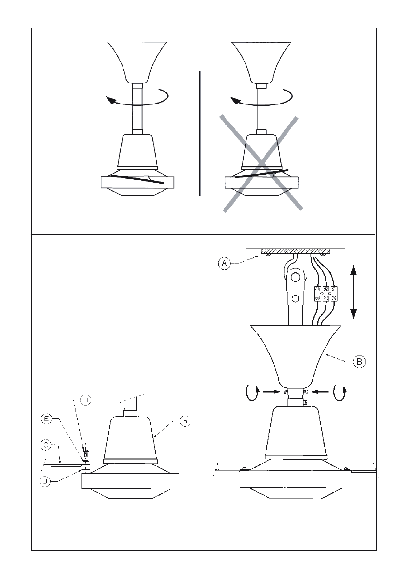
1.- Coloque las palas según la inclinación mostrada en la figura 5
2.- Una las palas (C) al conjunto motor más soporte (B) mediante los tornillos (D) y las arandelas
de seguridad (E). No olvide poner la protección de tela entre la pala y el motor para evitar posibles
ruidos. Repita este procedimiento con las demás palas. (Fig.6)
NOTA IMPORTANTE: Tenga precaución en no apoyarse sobre las palas, ya que éstas se podrían
desequilibrar y aumentaría el balanceo del ve
ntilador.
3.- Destornille los dos tornillos situados en la base de la copa decorativa y podrá acceder más fácilmente al punto de anclaje y a la regleta de conexión. Cuelgue el conjunto motor mas soporte (B)
en el gancho de la plancha de colgar (A) (previamente fijada en el techo). (Fig.7)
4 - Empalme los cables y ubíquelos correctamente. Mediante la copa decorativa disimule los empalmes y el punto de fijación. Atornille los dos tornillos situados en la base de la copa decorativa.
INSTALACIÓN ELÉCTRICA
NOTA IMPORTANTE: Antes de empezar a manipular la red eléctrica, quite los fusibles o des-
conecte el interruptor principal del suministro eléctrico.
según le convenga. (Fig.8)
Todos los ventiladores se suministran de la factoría con la dirección del flujo de aire hacia abajo.
-Si usted quiere variar frecuentemente la dirección del flujo de aire, ponga un conmutador de
cruce exterior. (Fig.9)
ATENCIÓN: Antes de canbiar la dir
espereque se haya parado la rotación del ventilador.
ección del sentido del flujo de aire, apague el ventilador y
7
eria ed ojufl led nóiccerid al ranimreted árdop ,ajile detsu euq nóixenoc ed ameuqse le núgeS -
Page 8

Fijación en una viga de madera
Se suministran dos tornillos (H) y arandelas de seguridad (I) para poder fijar el soporte de chapa (A) en una
viga de madera. El agujero para el tornillo no debe ser de más diámetro que el diámetro del tornillo.
Asegúrese que la viga de madera sea capaz de soportar el peso del ventilador en movimiento
(mínimo 25/40Kg). (Fig.4)
ENSAMBLAJE DEL VENTILADOR
NOTA IMPORTANTE: Si va a instalar más de un ventilador, asegúrese de no mezclar las palas
de las hélices de distintos ventiladores, aunque sean del mismo modelo.
1.- Coloque las palas según la inclinación mostrada en la figura 5
2.- Una las palas (C) al conjunto motor más soporte (B) mediante los tornillos (D) y las arandelas
de seguridad (E). No olvide poner la protección de tela entre la pala y el motor para evitar posibles
ruidos. Repita este procedimiento con las demás palas. (Fig.6)
NOTA IMPORTANTE: Tenga precaución en no apoyarse sobre las palas, ya que éstas se podrían
desequilibrar y aumentaría el balanceo del ventilador.
3.- Destornille los dos tornillos situados en la base de la copa decorativa y podrá acceder más fá-
cilmente al punto de anclaje y a la regleta de conexión. Cuelgue el conjunto motor mas soporte (B)
en el gancho de la plancha de colgar (A) (previamente fijada en el techo). (Fig.7)
4 - Empalme los cables y ubíquelos correctamente. Mediante la copa decorativa disimule los empal-
mes y el punto de fijación. Atornille los dos tornillos situados en la base de la copa decorativa.
INSTALACIÓN ELÉCTRICA
NOTA IMPORTANTE: Antes de empezar a manipular la red eléctrica, quite los fusibles o des-
conecte el interruptor principal del suministro eléctrico.
- Según el esquema de conexión que usted elija, podrá determinar la dirección del flujo de aire
según le convenga. (Fig.8)
Todos los ventiladores se suministran de la factoría con la dirección del flujo de aire hacia abajo.
-Si usted quiere variar frecuentemente la dirección del flujo de aire, ponga un conmutador de
cruce exterior. (Fig.9)
ATENCIÓN: Antes de canbiar la dirección del sentido del flujo de aire, apague el ventilador y
espereque se haya parado la rotación del ventilador.
INSTRUCCIONES DE OPERACIÓN
1.- El regulador de velocidad, tiene cuatro posiciones:
1 .......... ALTA VELOCIDAD
MANTENIMIENTO
1.- La limpieza periódica es el único mantenimiento requerido.
2.- Limpie el ventilador con un cepillo blanco o un trapo suave para evitar daños al acabado.
3.- En el momento del mantenimiento, tenga precaución en no apoyarse sobre las palas, ya que
éstas se podrían desequilibrar y aumentaría el balanceo del ventilador.
4.- No utilice agentes de limpieza abrasivos, ya que estos pueden dañar el acabado.
5.- No utilice agua en la limpieza del ventilador ya que puede causar daños en el motor.
NOTA IMPORTANTE: Antes de iniciar el mantenimiento del ventilador, asegúrese de que está
desconectado de la red eléctrica.
0 .......... OFF
2 .......... MEDIA VELOCIDAD
3 .......... BAJA VELOCIDAD
8
Page 9
MANTENIMIENTO
1.- La limpieza periódica es el único mantenimiento requerido.
2.- Limpie el ventilador con un cepillo blanco o un trapo suave para evitar daños al acabado.
3.- En el momento del mantenimiento, tenga precaución en no apoyarse sobre las palas, ya que
éstas se podrían desequilibrar y aumentaría el balanceo del ventilador.
4.- No utilice agentes de limpieza abrasivos, ya que estos pueden dañar el acabado.
5.- No utilice agua en la limpieza del ventilador ya que puede causar daños en el motor.
NOTA IMPORTANTE: Antes de iniciar el mantenimiento del ventilador, asegúrese de que está
desconectado de la red eléctrica.
SOLUCIONAR PROBLEMAS
NOTA IMPORTANTE: Antes de manipular el ventilador, asegúrese de que está desconectado de
la red eléctrica.
Problema Causa problema Solución sugerida
Ventilador no arranca
Ventilador ruidoso
Ventilador tiembla o vibra
en exceso
1.Fusibles fundidos o interruptor general desconectado.
2.Conexiones flojas en las regletas de conexión.
3.Palas de la hélice no fijadas
al ventilador
4.Tornillos flojos.
5.Tornillos flojos entre las palas
y el soporte motor.
6.Las palas de la hélice no están bien asentadas.
7.El soporte no está bien sujetado al techo.
8.Las palas de la hélice están
fuera equilibrio.
1.Comprobar fusibles o interruptor general.
2.comprobar conexiones.
3.Unir palas al ventilador antes
de arrancar.
4.Comprobar todos los tornillos
del ventilador
5.Comprobar los tornillos que
fijan las palas a la carcasa del
motor y apretar si es necesario.
6.Comprobar que todas las palas están bien asentadas y con
el mismo ángulo de inclinación.
7.Comprobar el anclaje del soporte gancho.
8.Cambiar unas palas de posición.
ASISTENCIA TÉCNICA
La extensa red de Servicios Oficiales S&P garantiza una adecuada asistencia técnica.
En caso de observar alguna anomalía en el aparato, rogamos se ponga en contacto con cualquiera
de los servicios oficiales mencionados, donde será debidamente atendido.
Cualquier manipulación efectuada por personas ajenas a los Servicios Oficiales S&P nos obligaría
a cancelar su garantía.
Para aclarar cualquier duda con respecto a los productos S&P diríjase a la Red de Servicios Post
Venta si es en territorio español, o a su distribuidor habitual en el resto del mundo. Para su localización puede consultar la página WEB www.solerpalau.com
PUESTA FUERA DE SERVICIO Y RECICLAJE
• En caso de puesta en fuera de servicio, aunque sea de forma temporal, es aconsejable conservar el aparato en lugar seco y libre de polvo, dentro de su embalaje original.
• La normativa de la CEE y el compromiso que debemos adquirir con las futuras generaciones, nos obligan al reciclado de materiales; le rogamos que no olvide depositar todos
los elementos sobrantes del embalaje en los correspondientes contenedores de reciclaje, así como de llevar los aparatos sustituidos al Gestor de Residuos más próximo.
EL FABRICANTE NO SE HACE RESPONSABLE DE LOS DAÑOS PRODUCIDOS A PERSONAS Y/O
COSAS DEBIDOS AL INCUMPLIMIENTO DE ESTAS ADVERTENCIAS.
S&P SE RESERVA EL DERECHO A MODIFICACIONES DEL PRODUCTO SIN PREVIO AVISO.
9
Page 10

ENGLISH
Installation Manual and Operating Instructions
Caution : For safe operation and installation, read all instructions carefully
Neither the manufacture nor the manufacturer’s agent/distributor nor the retailer from whom
this product was purchased shall be in anyway responsible for any loss or damage of whatever
nature caused by the installation of this product
.
SAFETY INSTRUCTIONS
To ensure the success of the Ceiling Fan’s installation, be sure to read the
following general safety rules before begining.
1.- The Ceiling Fan installation should be carried out by a qualified electrician.
2.- To ensure a correct installation, be sure to read the instructions and review the diagrams thoroughly before commencement.
3.- All electrical connections must be carried out in accordance with local codes
and regulations, or the national Electrical Code. If you are unfamiliar with the
installation of electrical wiring, secure the services of a qualified electrician.
Before connecting the device, ensure that electrical supply and frequency
4.coincides with the technical dates indicated in technical plate.
5.- These apparatus must be earthed.
6.- The method of disconnection from the mains supply must incorporate a
switch or isolator with a minimum contact separation of 3 mm. on all poles.
7.- Make sure that when the fan is fitted in the chosen position there is not
possibility of the rotating blades coming into contact with any object.
Blades should be at least 2.30 m from floor when fan is hung.
8.- If you are installing more than one ceiling fan make sure that you do
mix fan blade sets, even though they are from the same ceiling fan model.
9.- Before beginning, disconnect power by removing fuse or turning off circuit breaker.
10.- Once fan installation is completed make sure that all connections are
secure to prevent fan from falling.
11.- Do not insert anything into the fan blades when ceiling fan is operating.
12.- This appliance can be used by children aged from 8 years and above and
persons with reduced physical, sensory or mental capabilities or lack of
experience and knowledge if they have been given supervision or instruction concerning use of the appliance in a safe way and understand the
hazards involved. Children shall not play with the appliance. Cleaning and
user maintenance shall not be made by children without supervision.
13.- Cleaning and maintenance to perform by the user not be made by chil-
dren without supervision.
not
10
Page 11

10-Once fan installation is completed make sure that all connections are secure to prevent fan from
falling.
11-Do not insert anything into the fan blades when ceiling fan is operating.
14.- Each fan will be controlled by its selector. The selector cannot be used
to control by more than one fan.
IMPORTANT NOTE: The warnings, safeguards and instructions given in this manual are not
exhaustive and do not nessecarily cover all eventualities. It must be understood that common sense,
caution and care are factors which cannot be built into any product. These factors must be supplied
by the person(s) caring for and operating the unit.
UNPACKING INSTRUCTIONS
Before assembling the ceiling fan, remove all parts from the shipping carton and check them against
the parts listed below (Fig. 1 ) :
A- Support plate (1 pc.)
B- Motor assembly and support (1 pc.)
C- Blades (3 pcs.)
D- Blade fitting screw (6 pcs.)
E- Washers (6 pcs.)
F- Speed regulator (1 pc.)
G- Wall plugs (2 pcs.)
H- Screws (2 pcs.)
I- Washers ( 2 pcs.)
J- Felt washers ( 3pcs )
Instructions Manual
INSTALLATION INSTRUCTION
FITTING THE FAN TO THE CEILING
Important: To avoid the possibility of accidents caused by the fan, which could imply legal
responsibilities for the installer, compliance with each of the following instructions is essential.
Ensure that the distance between the lowest point of the fan, once installed, and the floor is at least
2.3 metres.
Check that the means of fitting the fan to the ceiling is capable of supporting the weight of the fan
when in operation. (HTB 75 N / HTB 90 N Minimum 25 Kg. - HTB 150 N Minimum 40 Kg. ).
Fitting to a concrete ceiling
To ensure correct installation, drill four holes of the same diameter as the wall plugs (G) in the
concrete ceiling. Insert the plugs supplied and fix the support plate (A) using the four screws (H)
and washers (I) provided. (Fig.2).
Fitting to a false ceiling
Make a hole in the false ceiling that is large enough to allow the introduction of a rigid, wooden or
metal cross beam. This should be as long as possible and under no circumstances less than 25cm.
in length, to allow the best distribution of the weight of the fan.
Without reducing its ability to support the fan, make a small groove at the centre of the crossbeam,
then locate the beam so that its centre coincides with the hole in the ceiling.
11
Page 12

Join the support plate (A) to the crossbeam using galvanised metal wire of at least 2.5mm in diameter.
Passing the wire through the grooves in the plate, wind it around the crossbeam and back through
the plate a minimum of six times, so that at least some of the turns pass through the groove in the
Join the support plate (A) to the crossbeam using galvanised metal wire of at least 2.5mm in diameter.
Passing the wire through the grooves in the plate, wind it around the crossbeam and back through
crossbeam. Secure the wire by twisting it around itself several times.
Ensure that the ceiling is able to support the weight of the fan when in operation (minimum 25/40
Kg.). (Fig.3)
Fitting to a wooden beam
Four screws (H) are supplied together with safety washer’s (I) for fitting the support plate (A) to a
wooden beam. The holes for the screws should not be of greater diameter than the diameter of the
screw. Ensure that the wooden beam is able to support the weight of the moving fan (minimum
25/40 Kg.) (Fig.4)
ASSEMBLY OF THE FAN
IMPORTANT: If you installing more than one fan, ensure that you do not mix the fan blade sets, even
though they are from the same ceiling fan model.
1.- Fit the blades with the angles as shown in figure 5
2.- Fit the blades (C) to the motor assembly and support (B) using the screws (D) and the safety
washers (E). Do not forget to use the felt protection washers between the blade and the motor
assembly to avoid possible noise. Repeat this process with the remaining blades. (Fig.6)
IMPORTANT: Be careful not to support yourself on the fan blades, as these could then become
unbalanced and cause vibration or shaking of the fan.
3.- Loosen the screws situated in the base of the decorative canopy to allow easier access to the
anchorage point and electrical connectors. Hang the motor and support assembly (B) from the hook
on the support plate (A) (previously fixed to the ceiling) (Fig.7)
4.- Connect the cables and position them correctly. The connections and the fitting
hidden using the decorative canopy.
point can be
INSTALLATION ELECTRICAL
IMPORTANT SAFETY NOTICE: Before installation, ensure that the electrical supply is disconnected
at the mains junction / fuse box.
accordance with (Fig.8)
- All products are supplied, factory wired, for a downward airflow configuration.
- If the airflow direction is required to be changed on a frequent basis, then an airflow direction
switch should be installed as a separate additional accessory (Fig.9)
IMPORTANT: Before changing the direction of ariflow, the fan blades must have completely stopped
turning after switching the unit to the off position.
12
ni noitarugfinoc noitcennoc gniriw eht nopu gnidneped degnahc eb nac noitcerid woflria ehT -
Page 13

Fitting to a wooden beam
Four screws (H) are supplied together with safety washer’s (I) for fitting the support plate (A) to a
wooden beam. The holes for the screws should not be of greater diameter than the diameter of the
screw. Ensure that the wooden beam is able to support the weight of the moving fan (minimum
25/40 Kg.) (Fig.4)
ASSEMBLY OF THE FAN
IMPORTANT: If you installing more than one fan, ensure that you do not mix the fan blade sets, even
though they are from the same ceiling fan model.
1.- Fit the blades with the angles as shown in figure 5
2.- Fit the blades (C) to the motor assembly and support (B) using the screws (D) and the safety
washers (E). Do not forget to use the felt protection washers between the blade and the motor
assembly to avoid possible noise. Repeat this process with the remaining blades. (Fig.6)
IMPORTANT: Be careful not to support yourself on the fan blades, as these could then become
unbalanced and cause vibration or shaking of the fan.
3.- Loosen the screws situated in the base of the decorative canopy to allow easier access to the
anchorage point and electrical connectors. Hang the motor and support assembly (B) from the hook
on the support plate (A) (previously fixed to the ceiling) (Fig.7)
4.- Connect the cables and position them correctly. The connections and the fitting point can be
hidden using the decorative canopy.
INSTALLATION ELECTRICAL
IMPORTANT SAFETY NOTICE: Before installation, ensure that the electrical supply is disconnected
at the mains junction / fuse box.
- The airflow direction can be changed depending upon the wiring connection configuration in
accordance with (Fig.8)
- All products are supplied, factory wired, for a downward airflow configuration.
- If the airflow direction is required to be changed on a frequent basis, then an airflow direction
switch should be installed as a separate additional accessory (Fig.9)
IMPORTANT: Before changing the direction of ariflow, the fan blades must have completely stopped
turning after switching the unit to the off position.
OPERATION INSTRUCTIONS
1. – The speed regulator has four positions.
1 ......... High speed
2 ......... Medium speed
3 ......... Low speed
MAINTENANCE
PROBLEM SOLVING
IMPORTANT: Before working on the fan ensure that it is disconnected from the mains electricity
supply.
Problems Possible cause Suggested solution
Fan does not start
Fan sounds noisy
Fan sounds noisy
0 .........OFF
1.- Periodic cleaning is the only maintenance required.
2.- Clean the fan using a soft brush or soft cloth to avoid damaging the finish.
3.- When carrying out maintenance work, do not use the fan blades as a support as they
could become unbalanced and so increase the vibration of the fan.
4.- Do not use abrasive cleaning agents as these could damage the finish of the fan.
5.- Do not use water when cleaning the fan as this could cause damage to the motor and
deform the fan blades.
IMPORTANT: Before carrying out any maintenance work on the fan, ensure that it is
disconnected from the mains electrical supply.
1. Blown fuse or circuit breaker.
2. Loose connections to the
mains supply
3. Fan blades not attached to
fan.
4. Loose screws.
5. Loose screws between fan
blades and motor housing.
6. Fan blades not seated properly.
7. Support plate not securely
fitted to ceiling.
8. Fan blades out of balance.
1. Check fuses or circuit breaker.
2. Tighten connections
3. Fit blades before starting fan.
4. Check all fan screws for
tightness.
5. Check fan blade screws
for tightness. Tighten if
necessary.
6. Check the fan blades sit
snugly
in the motor housing
and with the same angle of
inclination.
7. Check ceilin g su pport
screws.
8. Change the position of some
of the blades.
13
Page 14

FRANÇAIS
NOTICE D’INSTALLATION ET D’UTILISATION
Avertissement: Lire toute la notice avec attention afin de réaliser une installation sure et bien
utiliser l’appareil.
Ni le fabricant, ni le distributeur, ni le point de vente où a été acheté ce produit, ne sera tenu
responsable des dommages occasionnés par une mauvaise installation.
TECHNICAL ASSISTANCE
S&P’s large Technical Service network will guarantee adequate technical assistance.
If a fault is observed in the unit, please contact any of the mentioned technical service offices and
they will attend to your problem.
Any manipulation of the appliance by personnel not belonging to the Official S&P Services will result
in your guarantee being void.
For any queries regarding S&P products please contact any branch of our After Sales Service network if you are in Spain, or your regular dealer in the rest of the world. To find your nearest dealer,
visit our website at www.solerpalau.com
REMOVAL FROM SERVICE, DISPOSAL AND RECYCLING
• If the appliance is not to be used for any length of time, we recommend returning it to
its original package and storing it in a dry, dust-free place.
• EU regulations and our commitment to future generations oblige us to recycle used
materials; please remember to dispose of all unwanted packaging materials at the
appropriate recycling points, and to drop off obsolete equipment at the nearest waste
management point.
THE MANUFACTURER WILL NOT BE HELD LIABLE FOR DAMAGES TO PEOPLE AND/OR PROPERTY DUE TO NON-COMPLIANCE WITH THESE WARNINGS.
S&P RESERVES THE RIGHT TO MODIFY THE PRODUCT WITHOUT PRIOR NOTIFICATION.
14
Page 15

FRANÇAIS
NOTICE D’INSTALLATION ET D’UTILISATION
Avertissement: Lire toute la notice avec attention afin de réaliser une installation sure et bien
utiliser l’appareil.
Ni le fabricant, ni le distributeur, ni le point de vente où a été acheté ce produit, ne sera tenu
responsable des dommages occasionnés par une mauvaise installation.
RÉCOMMANDATIONS DE SÉCURITÉ
Pour réaliser une installation correcte et sûre du ventilateur de plafond, lire
attentivement les normes de sécurité suivantes ainsi que toute cette notice
avant de commencer son montage.
1.- L’installation du ventilateur doit être réalisée par un professionnel qualifié.
2.- Tous les raccordements électriques doivent être conformes aux normes
en vigueur.
Avant de brancher l’appareil, assurez-vous que la tension d’alimentation
3.-
et la fréquence correspondent aux données techniques indiquées sur la
plaque de caractéristiques de l’appareil.
4.- Ces appareils sont prévus pour être raccordés à une prise de terre.
5.- En cas de raccordement direct au réseau, la ligne électrique devra prévoir un interrupteur omnipolaire ayant une ouverture entre contacts d’au
moins 3 mm, bien dimensionné par rapport à la charge et conforme aux
normes en vigueurs.
6.- S’assurer que le lieu d’installation permet la libre rotation de l’hélice. Une
fois le ventilateur installé, l’hélice doit se situer à une distance supérieure
à 2,30 m au-dessus du sol.
7.- Si plusieurs ventilateurs doivent être installés prendre soin de ne pas mélanger les pales des hélices des différents ventilateurs même s’ils sont
identiques.
8.- Avant d’installer et de raccorder le ventilateur de plafond vérifier que la
ligne d’alimentation électrique est déconnectée du réseau.
9.- Après installation du ventilateur vérifier que toutes les fixations sont correctes pour éviter la chute du ventilateur.
10.- Ne jamais insérer un objet entre les pales du ventilateur quand il est en
mouvement.
11.-
Cet appareil peut être utilisé par des enfants âgés de 8 ans et plus et par
des personnes dont les capacités physiques, sensorielles ou mentales
sont réduites ou des personnes dénuées d’expérience ou de connaissance, sauf si elles ont pu bénéficier, par l’intermédiaire d’une personne
responsable de leur sécurité, d’une surveillance ou d’instructions préalables concernant l’utilisation de l’appareil. Les enfants ne doivent pas
jouer avec l’appareil. Le nettoyage et l’entretien à réaliser par l’utilisateur
ne doivent pas être réalisés par des enfants sans surveillance.
12.- Nettoyage et entretien par l’utilisateur ne doivent être pas fabriqués par
des enfants sans surveillance.
15
Page 16

10. Ne jamais insérer un objet entre les pales du ventilateur quand il est en mouvement.
CONTENU DE L’EMBALLAGE
Avant de monter le ventilateur de plafond, sortir toutes les pièces de l’emballage et vérifier que
tous les composants de la liste suivante sont bien présents. (Fig.1)
A- Support crochet. (1 pièce)
B- Ensemble moteur-support. (1 pièce)
C- Pales. (3 pièces)
D- Vis de fixation des pales. (6 pièces)
E- Rondelles de sécurité. (6 pièces)
F- Variateur de vitesse. (1 pièce)
G- Chevilles. (2 pièces)
H- Vis de fixation. (2 pièces)
I- Rondelles de sécurité. (2 pièces)
J- Protection de pale. (3 pièces)
Notice d’instruction
13.- Chaque ventilateur doit être contrôlé par sa commande 4 positions. Ne
pas contrôler plusieurs ventilateurs avec une seule commande.
NOTE IMPORTANTE: Les instructions, quant au montage et la sécurité, données dans cette notice
n’ont pas la prétention de répertorier toutes les situations possibles. Le bon sens et la prudence
sont des facteurs qui doivent être toujours présents pour les personnes utilisant les ventilateurs et
qui en assurent l’entretien.
CONTENU DE L’EMBALLAGE
Avant de monter le ventilateur de plafond, sortir toutes les pièces de l’emballage et vérifier que
tous les composants de la liste suivante sont bien présents. (Fig.1)
A- Support crochet. (1 pièce)
B- Ensemble moteur-support. (1 pièce)
C- Pales. (3 pièces)
D- Vis de fixation des pales. (6 pièces)
E- Rondelles de sécurité. (6 pièces)
F- Variateur de vitesse. (1 pièce)
G- Chevilles. (2 pièces)
H- Vis de fixation. (2 pièces)
I- Rondelles de sécurité. (2 pièces)
J- Protection de pale. (3 pièces)
Notice d’instruction
INSTRUCTIONS D’INSTALLATION
FIXATION DU VENTILATEUR DE PLAFOND
NOTE IMPORTANTE: Suivre toutes les indications données afin d’éviter la chute du ventilateur qui
pourrait entraîner la responsabilité de l’installateur en cas d’accident.
Assurer que la distance entre le point le plus bas du ventilateur, une fois installé, et le sol est supérieure
à 2,30 mètres.
S‘assurer que le point de fixation du ventilateur est capable de supporter le poids du ventilateur en
mouvement (HTB 75 N / HTB 90 N - minimum 25 kg. - HTB 150 N - minimum 40 kg.)
Fixation à un plafond en ciment
Pour assurer une fixation correcte, percer le plafond au diamètre des chevilles (G) fournies avec
l’appareil. Insérer les 2 chevilles et fixer le support crochet en tôle (A) avec les vis (H) et rondelles
(I) fournies. (Fig.2)
Fixation à un faux plafond
Après avoir vérifié que le faux plafond est assez résistant pour supporter le ventilateur en mouvement
(minimum 25/40 kg) (Fig. 3), pratiquer une ouverture dans le faux plafond, suffisamment grande
pour passer une traverse rigide, métallique ou en bois,
à 25 cm de longueur afin de fin d’assurer une bonne répartition du poids.
Faire une petite entaille au centre de la traverse sans que cela ne la fragilise.
la plus longue possible, et jamais inférieure
16
Page 17

Placer la traverse de façon à ce que l’ouverture dans le faux plafond coïncide avec le centre de la
traverse.
Placer la traverse de façon à ce que l’ouverture dans le faux plafond coïncide avec le centre de la
traverse.
Relier le support crochet en tôle (A) avec la traverse avec un fil de fer en acier galvanisé ayant un
diamètre minimal de 2,5 mm. Faire un minimum de 6 tours en passant par la rainure. Finalement
faire quelques tours autour des boucles de fil de fer
Fixation à une poutre en bois
Après avoir vérifié que la poutre est assez résistante pour supporter le ventilateur en mouvement
(minimum 25/40 kg.) (Fig. 4).
Deux vis (H) et rondelles de sécurité (I) sont fournies pour fixer le support crochet en tôle (A) à une
poutre en bois.
MONTAGE DU VENTILATEUR
NOTE IMPORTANTE: Si plusieurs ventilateurs doivent être installés prendre soin de ne pas
mélanger les pales des hélices des différents ventilateurs même s’ils sont identiques.
1. Placer la pale avec l’inclinaison indiquée figure 5
2. Fixer les pales (C) à l’ensemble moteur-support (B) avec les vis (D) et les rondelles de sécurité
(E) sans oublier la protection (J) entre les pales et le moteur pour limiter les transmissions de
vibrations (Fig.6)
NOTE IMPORTANTE: Prendre soin de ne pas appuyer sur les pales une fois montées pour
ne pas les déformer. Ceci pourrait entraîner un déséquilibre du ventilateur et augmenter son
balancement.
3. Dévisser les deux vis situées à la base du cache en forme de cône situé en partie supérieure,
afin d’accéder au point de suspension et au bornier de raccordement. Suspendre le ventilateur
(B) au crochet du support en tôle (A) (Fig.7)
4. Replacé le cache conique pour dissimuler
électrique, puis serrer les deux vis de fixation.
le point de suspension et le bornier de raccordement
INSTALLATION ELECTRIQUE
NOTE IMPORTANTE: Avant d’installer et de raccorder le ventilateur vérifier que la ligne
d’alimentation électrique est déconnectée du réseau.
- En fonction du schéma de raccordement, il est possible de choisir le sens de l'air selon les
besions de l'installation (Fig. 8)
Tous les ventilateurs sont fournis d'usine avec le flux d'air dirigé vers la bas.
- S'il est nécessaire de changer périodiquement le sens de l'air, pérvoir un commutateur inverseur.
(Fig. 9)
ATENTION: Avant changer le sens de l'air, couper l'alimentation et attendre que le ventilateur ce
soit complèmentament immobilisé.
17
Page 18

Fixation à une poutre en bois
Après avoir vérifié que la poutre est assez résistante pour supporter le ventilateur en mouvement
(minimum 25/40 kg.) (Fig. 4).
Deux vis (H) et rondelles de sécurité (I) sont fournies pour fixer le support crochet en tôle (A) à une
poutre en bois.
MONTAGE DU VENTILATEUR
NOTE IMPORTANTE: Si plusieurs ventilateurs doivent être installés prendre soin de ne pas
mélanger les pales des hélices des différents ventilateurs même s’ils sont identiques.
1. Placer la pale avec l’inclinaison indiquée figure 5
2. Fixer les pales (C) à l’ensemble moteur-support (B) avec les vis (D) et les rondelles de sécurité
(E) sans oublier la protection (J) entre les pales et le moteur pour limiter les transmissions de
vibrations (Fig.6)
NOTE IMPORTANTE: Prendre soin de ne pas appuyer sur les pales une fois montées pour
ne pas les déformer. Ceci pourrait entraîner un déséquilibre du ventilateur et augmenter son
balancement.
3. Dévisser les deux vis situées à la base du cache en forme de cône situé en partie supérieure,
afin d’accéder au point de suspension et au bornier de raccordement. Suspendre le ventilateur
(B) au crochet du support en tôle (A) (Fig.7)
4. Replacé le cache conique pour dissimuler le point de suspension et le bornier de raccordement
électrique, puis serrer les deux vis de fixation.
INSTALLATION ELECTRIQUE
NOTE IMPORTANTE: Avant d’installer et de raccorder le ventilateur vérifier que la ligne
d’alimentation électrique est déconnectée du réseau.
- En fonction du schéma de raccordement, il est possible de choisir le sens de l'air selon les
besions de l'installation (Fig. 8)
Tous les ventilateurs sont fournis d'usine avec le flux d'air dirigé vers la bas.
- S'il est nécessaire de changer périodiquement le sens de l'air, pérvoir un commutateur inverseur.
(Fig. 9)
ATENTION: Avant changer le sens de l'air, couper l'alimentation et attendre que le ventilateur ce
soit complèmentament immobilisé.
INSTRUCTIONS D’UTILISATION
1- Le variateur de vitesse possède 4 positions:
0......... ARRET
1......... GRANDE VITESSE
2......... MOYENNE VITESSE
3......... PETITE VITESSE
ENTRETIEN
NOTE IMPORTANTE: Avant de procéder à l’entretien du ventilateur, vérifier que la ligne d’alimentation
électrique est déconnectée du réseau.
Au cours du nettoyage faire attention à ne pas prendre appuis sur les pales. Leur déformation pourrait
entraîner un déséquilibre du ventilateur et augmenter son balancement.
1. Un nettoyage régulier est le seul entretien exigé
2. Nettoyer le ventilateur avec un chiffon doux pour ne pas abîmer les pales.
3. Ne pas utiliser de détergent abrasif.
4. Ne pas envoyer d’eau sur le moteur.
SOLUTIONNER DES PROBLEMES SIMPLES
Problème Cause du problème Solution suggérée
Ventilateur ne démarre pas
Ventilateur bruyant
Ventilateur vibre
excessivement
1. Fusible fondus ou
disjoncteur déconnecté.
2. Mauvaise connexion au
bornier de raccordement.
3. Pales mal fixées au moteursupport
4. Vis desserrées
5. Vis de fixation des pales
desserrées
6. Les pales sont mal
montées.
7. Le support est mal fixé au
plafond
8. Le ventilateur est
déséquilibré.
1.Changer le fusible ou
enclencher le disjoncteur.
2.Vérifier le raccordement
électrique au bornier.
3.Resserrer les vis de fixation
des pales
4. Vérifier toutes les vis de
fixation du ventilateur
5.Vérifier toutes les vis de
fixation et les resserrer si
nécessaire.
6.Vérifier que toutes les pales
soient montées dans le
même sens.
7.Vérifier la fixation du support
crochet.
8.Vérifier que les pales ne
soient pas déformées.
18
Page 19

ASSISTANCE TECHNIQUE
Pour toute anomalie de l’appareil prendre contact avec votre distributeur.
Toute manipulation effectuée par des personnes n’appartenant pas aux services officiels S&P entraînera l’annulation de votre garantie.
Pour toute précision ou répondre à toutes vos questions concernant les produits S&P veuillez vous
adresser à votre distributeur habituel.
Vous trouverez son adresse sur notre site www.solerpalau.com
MISE HORS SERVICE ET RECYCLAGE
• En cas de mise hors service, même temporaire, il est conseillé de ranger l’appareil
dans un endroit sec et sans poussière, dans son emballage original.
• La norme de la CEE et l’engagement que nous devons maintenir envers les futures
générations nous obligent à recycler le matériel; nous vous prions de ne pas oublier
de déposer tous les éléments restants de l’emballage dans les containers correspondants de recyclage, et d’emmener les appareils remplacés au Gestionnaire de
Déchets le plus proche.
LE FABRICANT NE SERA PAS RESPONSABLE DES DOMMAGES SURVENUS À DES PERSONNES
ET/OU DES OBJETS DUS AU NON RESPECT DE CES AVERTISSEMENTS.
S&P EST HABILITÉ À RÉALISER DES MODIFICATIONS DU PRODUIT SANS EN AVERTIR LE
CLIENT À L’AVANCE.
19
Page 20

PORTUGUÊS
MANUAL DE INSTALAÇÃO E INSTRUÇÕES DE USO
AVISO: Leia atentamente todas as instruções para assegurar um funcionamento e uma
instalação segura do equipamento.
Nem o fabricante nem o distribuidor nem o comerciante têm responsabilidade por algum dano
ou perdas ocasionadas pela instalação do aparelho.
PRECAUÇÕES DE SEGURANÇA
Para uma instalação segura do seu ventilador de tecto, leia as seguintes
normas de segurança antes de iniciar a instalação.
1.- A instalação do ventilador deve ser executada por um técnico qualificado.
2.- Para assegurar uma instalação perfeita, leia o manual de instruções e
estude os diagramas antes de iniciar a instalação.
3.- Todas as ligações eléctricas devem conferir as normas locais e nacionais
vigentes. Se não está familiarizado com as instalações eléctricas solicite
os serviços de um técnico qualificado.
È imprescindível comprovar que as características eléctricas (voltagem,
4.intensidade, freqüência, etc.) que constam na placa do motor são compatíveis com as da instalação.
5.- Estes aparelhos devem ser ligados a uma ficha com ligação terra.
6.- Os meios de interrupção que devem ser incorporados na instalação fixa
para sua interrupção omnipolar da rede de alimentação, devem apresentar
uma separação de contactos com pelo menos 3 mm em todos os pólos.
7.- Assegure-se que o lugar da instalação deixa a rotação da hélice do ventilador livre. A hélice deve estar a pelo menos 2,30 mts do solo.
8.- Se instalar mais do que um ventilador assegure-se para não misturar as
palas das hélices de diferentes ventiladores, mesmo que sejam do mesmo modelo.
9.- Antes de começar a instalação na rede eléctrica, retire os fusíveis ou desligue o interruptor principal do alimentador eléctrico.
10.- Depois de instalar o ventilador, certifique-se que todas as fixaçõe estão
correctas afin de evitar uma queda do ventilador.
11.- Nunca introduza objectos entre as palas da hélice enquanto o ventila-
dor está em movimento.
12-
Este aparelho pode ser utilizado por crianças com idade de 8 anos ou
superior e pessoas com capacidades físicas, sensoriais ou mentais reduzidas ou falta de experiencia e conhecimento, se lhes tiver sido dado
a supervisão ou formação apropiadas no que diz respeito ao uso do
aparelho de uma maneira segura e que comprendam os perigos que
implica. As crianças nao devem brincar com o aparelho. A limpeza e
Manutenção a realizar pelo usuário nao debe ser realizada por crianças
sem supervisão.
13.- A limpeza e Manutenção a realizar pelo utilizador nao debe ser realizado
por crianças sem supervisão.
20
Page 21

9- Antes de começar a instalação na rede eléctrica, retire os fusíveis ou desligue o interruptor
principal do alimentador eléctrico.
10- Depois de instalar o ventilador,
que todas as estão correctas de evitar
uma queda do ventilador.
11- Nunca introduza objectos entre as palas da hélice enquanto o ventilador está em movimento.
14.- Cada ventilador tem de ser controlado pelo seu regulador. Não pode
utilizar um regulador para controlar mais de um ventilador.
NOTA IMPORTANTE: As instruções e mecanismos de segurança que aparecem neste manual
de instruções não pretende assegurar todas as possibilidades, situações e condições que podem
ocorrer. Deve-se entender que num sentido comum, precauções e cuidados são factores que não
se pode incluir dentro do produto. Estes factores são detectados pelas pessoas que mantêm e
operam o ventilador.
INSTRUÇÕES PARA DESEMBALAR
Antes de montar o ventilador de tecto, retire as peças de dentro da embalagem e comprove que
todos os componentes da lista estão incluídos
A- Suporte gancho (1 unidades)
B- Conjunto motor mais suporte (1 unidades)
C- Pás (3 unidades)
D- Parafusos para
E- Anilhas de segurança (6 unidades)
F- Conjunto regulador de velocidade (1 unidade)
G- Buchas (2 unidades)
H- Parafusos de
I- Anilhas de segurança (2 unidades)
J- Protecção da tela (3 unidades)
Manual de instruções
as pás (6 unidades)
(2 unidades)
INSTRUÇÕES DE INSTALAÇÃO
FIXAÇÃO DO VENTILADOR DE TECTO
NOTA IMPORTANTE: Siga cada uma das indicações que se seguem, desta forma evitar-se-á a
possibilidade de provocar um acidente por queda do aparelho, que poderia chegar a derivar em
responsabilidades penais para o instalador.
Assegure-se de que a distância desde a parte mais baixa do ventilador, uma vez instalado, se
situe a pelo menos 2,30 metros do solo.
Comprove que o ponto de
movimento (HTB 75 N / HTB 90 N mínimo 25 Kg. - HTB 150 N mínimo 40 Kg. ).
FIXAÇÃO NUM TECTO DE BETÃO
Para assegurar uma
buchas (G). Aplique as buchas fornecidas e
(H) e as anilhas (I) fornecidas para este propósito
FIXAÇÃO NUM TECTO DE POUCA RESISTÊNCIA
Abra uma brecha no tecto falso,
madeira o mais largo possível e nunca inferior a 25 cm de comprimento,
melhor repartição do peso do ventilador.
Situe a trave, onde previamente se fez uma pequena ranhura, de forma que a brecha do tecto
coincida com a sua parte central, de maneira a não debilitar a sua resistência mecânica.
Fixe o suporte de chapa (A), através das suas ranhuras, e a trave com um arame de ferro
galvanizado de 2,5 mm de diâmetro, no mínimo.
Repita este processo pelo menos seis vezes, procurando que algumas das vezes passe pela
ranhura da trave. No
Assegure-se que o tecto é capaz de suportar o peso do ventilador em movimento (mínimo 25/40
adequada, aplique dois furos no tecto de betão com o diâmetro das
ajuste bem o arame com algumas voltas em si mesmo.
do aparelho é capaz de suportar o peso do ventilador em
o suporte de chapa (A) mediante os dois parafusos
.
para introduzir por ela uma trave rígida de metal ou
de assegurar uma
21
Page 22

ranhura da trave. No ajuste bem o arame com algumas voltas em si mesmo.
Assegure-se que o tecto é capaz de suportar o peso do ventilador em movimento (mínimo 25/40
FIXAÇÃO NUMA VIGA DE MADEIRA
Fornece-se os parafusos (H) e as anilhas de segurança (I) para poder
o suporte de chapa
(A) numa viga de madeira. O furo para o parafuso não deve ser mais largo que o próprio parafuso.
que a viga de madeira seja capaz de suportar o peso do ventilador em movimento
situados na base da mesma.
FIXAÇÃO NUMA VIGA DE MADEIRA
(A) numa viga de madeira. O furo para o parafuso não deve ser mais largo que o próprio parafuso.
Fornece-se os parafusos (H) e as anilhas de segurança (I) para poder
o suporte de chapa
(mínimo 25/40 Kg) (Fig.4)
MONTAGEM DO VENTILADOR
NOTA IMPORTANTE: Se for instalar mais de que um ventilador, assegure-se que não são trocadas
as pás das hélices dos ditos ventiladores, nem que sejam do mesmo modelo.
1- Coloque as pás segundo inclinação apresentada na FIGURA 5.
2- Una as pás (C) ao conjunto motor mais suporte (B) mediante os parafusos (D) e as anilhas de
segurança (E). Não hesite em colocar a protecção de tela entre a pá e o motor para, assim, evitar
possíveis ruídos.
Repita este procedimento com as restantes pás
.
NOTA IMPORTANTE: Tenha a precaução de não se apoiar sobre as pás, pois estas poderão
desequilibrar e aumentar o balançar do ventilador.
3- Desaperte os parafusos situados na base da copa decorativa e poderá aceder mais facilmente
ao ponto de encaixe e à régua de ligações.
Pendure o conjunto motor mais suporte no gancho do suporte de chapa (A) (previamente
tecto)
4- Com a copa decorativa esconda as junções e o ponto de
.
Aparafuse os dois parafusos
ao
INSTALAÇÃO ELÉCTRICA
NOTA IMPORTANTE: Antes de começar a operar com a rede eléctrica, retire os fusíves ou desligue
o interruptor principal do quadro eléctrico.
Conforme o esquema de ligações que você escolha, poderá determinar a direcção do
que lhe convenha (Fig. 8)
Todos os ventiladores são fornecidos pela fabrica com o
Se você quiser variar frequentemente e inversâo do
comutador de inversão (Fig. 9)
ATENÇÃO: Antes de trocar a direcção do sentido do
este pare por completo.
de ar para baixo.
de ar a utilitzação de um
de ar, desligue o aparelho e espere que
de ar
INSTRUÇÕES DE FUNCIONAMENTO
1.- O regulador tem quatro posições:
0........ OFF
1........ VELOCIDADE RÁPIDA
2.........VELOCIDADE MÉDIA
3.........VELOCIDADE LENTA
MANUTENÇÃO
1- A limpeza periódica é a única manutenção necessária.
2- Limpe o ventilador com um espanador branco ou um pano suave para evitar danos no acabamento.
3- No momento da manutenção, tenha atenção em não se apoiar sobre as pás, pois estas poderão
desequilibrar e aumentar a balançar do ventilador.
4- Não utilize agentes de limpeza abrasivos, pois estes podem
o acabamento.
5- Não utilize água na limpeza do ventilador porque pode causar danos no motor.
NOTA IMPORTANTE: Antes de iniciar a manutenção do ventilador, assegure-se que este está
desligado da rede eléctrica.
22
Page 23

INSTALAÇÃO ELÉCTRICA
NOTA IMPORTANTE: Antes de começar a operar com a rede eléctrica, retire os fusíves ou desligue
o interruptor principal do quadro eléctrico.
Conforme o esquema de ligações que você escolha, poderá determinar a direcção do uxo de ar
que lhe convenha (Fig. 8)
Todos os ventiladores são fornecidos pela fabrica com o uxo de ar para baixo.
Se você quiser variar frequentemente e inversâo do uxo de ar aconselhámos a utilitzação de um
comutador de inversão (Fig. 9)
ATENÇÃO: Antes de trocar a direcção do sentido do uxo de ar, desligue o aparelho e espere que
este pare por completo.
INSTRUÇÕES DE FUNCIONAMENTO
1.- O regulador tem quatro posições:
0........ OFF
1........ VELOCIDADE RÁPIDA
2.........VELOCIDADE MÉDIA
3.........VELOCIDADE LENTA
MANUTENÇÃO
1- A limpeza periódica é a única manutenção necessária.
2- Limpe o ventilador com um espanador branco ou um pano suave para evitar danos no acabamento.
3- No momento da manutenção, tenha atenção em não se apoiar sobre as pás, pois estas poderão
desequilibrar e aumentar a balançar do ventilador.
4- Não utilize agentes de limpeza abrasivos, pois estes podem danicar o acabamento.
5- Não utilize água na limpeza do ventilador porque pode causar danos no motor.
NOTA IMPORTANTE: Antes de iniciar a manutenção do ventilador, assegure-se que este está
desligado da rede eléctrica.
SOLUCIONAR PROBLEMAS
PROBLEMA CAUSA DO PROBLEMA SOLUÇÃO SUGERIDA
Ventilador não arranca
Ventilador ruidoso
1-Fusíveis fundidos ou interrup-
tor geral desligado.
2-Ligações soltas na régua de
ligações.
3- Pás da hélice não xadas ao
ventilador.
4- Parafusos desapertados.
1-Vericar fusíveis.
2-Vericar ligações.
3- Unir as pás ao ventilador
antes de arrancar.
4- Vericar todos os parafusos
do ventilador.
Ventilador balança ou vibra
em excesso
ASSISTÊNCIA TÉCNICA
A extensa rede de Serviços Oficiais S&P garante uma adequada assistência técnica. No caso de
observar alguma anomalia neste aparelho, por favor contacte qualquer dos nossos serviços ofi
ciais mencionados, onde será devidamente atendido. Qualquer manipulação efectuada por pessoas
alheias aos Serviços Oficiais S&P obrigaria ao cancelamento da sua garantia. Para esclarecer qualquer dúvida relativa aos produtos S&P diríjase à Rede de Serviços Pós Venda se estiver em território
Espanhol, ou ao seu distribuidor habitual no resto do mundo. Localize o distribuidor da sua área na
página www.solerpalau.com
5- Parafusos desapertados entre
as pás e o suporte motor.
6- As pás da hélice não estão
bem assentes.
7- suporte não está bem ajus-
tado ao tecto.
8- As pás da hélice estão fora
de equilíbrio.
5- Verificar os parafusos que
xam as pás à carcassa do
motor e apertá-los se for
necessário.
6- Vericar se todas as pás estão
bem assentes e com o mesmo ângulo de inclinação.
7- Vericar o aperto do suporte
gancho.
8- Trocar a posição das pás.
PARAGEM DE UTILIZAÇÂO E RECICLAGEM
• Caso deixe de utilizar o aparelho, nem que seja temporariamente, aconselhamos a
conservar o aparelho num lugar seco e livre de pó, dentro da sua embalagem original.
• A normativa da CE e o nosso compromisso com as gerações futuras obriganos à
reciclagem dos materiais; agradecemos que deposite todos os elementos sobrantes
da embalagem em contentores próprios de reciclagem, e que leve os seus aparelhos
que está a substituir ao Gestor de Resíduos mais próximo.
O FABRICANTE NÃO SE RESPONSABILIZA PELOS DANOS PRODUZIDOS A PESSOAS E/OU COISAS ESULTANTES DO INCUMPRIMENTO DESTAS ADVERTÊNCIAS.
A S&P RESERVA-SE O DIREITO DE MODIFICAR O PRODUCTO SEM AVISO RÉVIO.
23
Page 24

ITALIANO
MANUALE D’INSTALLAZIONE E ISTRUZIONI
Avviso: Leggere tutte le istruzioni attentamente per eseguire correttamente e con sicurezza
l’installazione del prodotto.
Sia il Costruttore, sia l’Agente e o Distributore e o Rivenditore non sono responsabili per
eventuali danni causati dall’installazione di questo prodotto.
AVVERTENZE DI SICUREZZA
Per eseguire una installazione sicura del suo ventilatore da soffitto, legga le
seguenti norme di sicurezza generali prima di iniziare l’installazione.
1.- L’installazione deve essere effettuata da un installatore qualificato.
2.- Per una installazione a regola d’arte, legga il manuale delle istruzioni e
prenda visione dei diagrammi prima di iniziare l’installazione.
3.- Tutti i collegamenti elettrici devono essere eseguiti in conformità delle
normative vigenti a livello locale e nazionale. Se si è sprovvisti di nozioni
per installazioni elettriche rivolgersi ad un installatore qualificato.
4.-
Prima di collegare il prodotto ,verificare che la tensione di alimentazione e
la frenquenza coincida con i dati di targa indicati sull ventilatore.
5.- Questo apparecchio deve essere collegato con messa a terra.
6.- Gli accessori elettrici che saranno aggregati all’installazione fissa per
l’interruzione della alimentazione della rete devono avere una separazione
dei contatti elettrici di almeno 3 mm.
7.- Assicurarsi che l’area interessata all’installazione consenta la rotazione
delle pale del ventilatore e sia libera da ogni potenziale impedimento. Le
pale devono essere posizionate a 2,30 m minimo dal pavimento.
8.- elap el eralocsem id erative erotalitnev nu id ùip edeverp enoizallatsni’l eS
anche se si tratta dello stesso modello.
9.- Prima di iniziare i collegamenti, toglier
generale della rete elettrica.
10.- Ad installazione completata assicurarsi che tutti i punti di fissaggio sia-
no perfettamente bloccati per evitare la caduta del ventilatore.
11.- Mai inserire oggetti tra le pale della ventola a ventilatore funzionante.
12.- Questo prodotto è utilizzabile da bambini con almeno 8 anni di eta o su-
periore e da persone con capacita fisiche, sensoriali o mentali ridotte o
che mancano di esperienza e conoscenza del prodotto , se sono stati
supervisionati o formati appropriatamente rispetto all’uso dell’apparato
in maniera sicura e comprendendo i rischi che implica. I bambini non devono giocare con questo apparato. La pulizia e la manutenzione da parte
dell’utente non dovrebbero essere fatte dai bambini senza supervisione.
13.- Pulizia e manutenzione a effettuare per l’utente non devere essere fatta
da bambini senza supervisione.
14.- Ogni ventilatore è controllato con il suo regolatore. Non si potrà utilizza-
re un regolatore per controllare il funzionamento di più ventilatori.
e il fusibile o scollegare l’interruttore
24
Page 25

ITALIANO
MANUALE D’INSTALLAZIONE E ISTRUZIONI
Avviso: Leggere tutte le istruzioni attentamente per eseguire correttamente e con sicurezza
l’installazione del prodotto.
Sia il Costruttore, sia l’Agente e o Distributore e o Rivenditore non sono responsabili per
eventuali danni causati dall’installazione di questo prodotto.
NORME GENERALI PER LA SICUREZZA
Per eseguire una installazione sicura del suo ventilatore da soffitto, legga le seguenti norme
di sicurezza generali prima di iniziare l’installazione.
1-L’installazione deve essere effettuata da un installatore qualificato
2-Per una installazione a regola d’arte, legga il manuale delle istruzioni e prenda visione dei
diagrammi prima di iniziare l’installazione.
3-Tutti i collegamenti elettrici devono essere eseguiti in conformità delle normative vigenti a
livello locale e nazionale. Se si è sprovvisti di nozioni per installazioni elettriche rivolgersi
ad un installatore qualificato.
4-Tensioni di alimentazione : 230 V 50 Hz.
5-Questo apparecchio deve essere collegato con messa a terra.
6-Gli accessori elettrici che saranno aggregati all’installazione fissa per l’interruzione della
alimentazione della rete devono avere una separazione dei contatti elettrici di almeno 3
mm .
7-Assicurarsi che l’area interessata all’installazione consenta la rotazione delle pale del
ventilatore e sia libera da ogni potenziale impedimento. Le pale devono essere posizionate
a 2,30 m. minimo dal pavimento.
8-Se l’installazione prevede più di un ventilatore evitare di mescolare le pale anche se si
tratta dello stesso modello.
9-Prima di iniziare i collegamenti , togliere il fusibile
o scollegare l’interruttore generale della
rete elettrica.
10-Ad installazione completata assicurarsi che tutti i punti di fissaggio siano perfettamente
bloccati per evitare la caduta del ventilatore.
11-Mai inserire oggetti tra le pale della ventola a ventilatore funzionante.
NOTA IMPORTANTE: Le istruzioni e i concetti di sicurezza che compaiono in questo
metallico zincato del diametro di 2,5 mm minimo. Eseguire almeno sei legature assicuran-
manuale non pretendono di far fronte a tutte le situazioni o condizioni particolari che si possono evidenziare al momento dell’installazione. E’ evidente che il buon senso unitamente
a precauzione e attenzione sono fattori che non si possono includere in nessun manuale e
che sono patrimonio delle persone qualificate che installano e manipolano il ventilatore.
ISTRUZIONE DI DISIMBALLO
Prima di procedere al montaggio del ventilatore da soffitto , togliere tutti i componenti della
lista inclusa. ( Fig. 1 )
A- Supporto gancio ( 1 pezzo )
B- Gruppo motore con supporto ( 1 pezzo )
C- Pale ( 3 pezzi )
D- Viti per il fissaggio delle pale ( 6 pezzi )
E- Rondelle di sicurezza ( 6 pezzi )
F- Regolatore di velocità ( 1 pezzo )
G- Tasselli ( 2 pezzi )
H- Viti di fissaggio ( 2 pezzi )
I- Rondelle di sicurezza ( 2 pezzi )
J- Protettori in tela ( 3 pezzi )
Manuale d’istruzione
ISTRUZIONI PER L’INSTALLAZIONE
FISSAGGIO DEL VENTILATORE AL SOFFITTO
NOTA IMPORTANTE : Seguire attentamente ogni indicazione che segue per evitare la
possibilità di provocare incidenti per la caduta del ventilatore che potrebbero comportare
una responsabilità penale per l’installatore.
Accertarsi che la distanza dal punto più basso del ventilatore installato , al pavimento sia
come minimo di 2,30 metri.
Controllare e verificare che il punto di fissaggio del ventilatore sia capace di sostenere il
peso del ventilatore in movimento
(
HTB 75 N / HTB 90 N
Fissaggio a soffitto in cemento
Praticare due fori nel soffitto del diametro del tassello ( G ) . Inserire i tasselli forniti e fissare
il supporto in lamiera ( A ) con le viti ( H ) e le rondelle ( I ) ( Fig. 2 )
Fissaggio a un soffitto di scarsa resistenza.
Praticare una apertura nel falso soffitto sufficiente, per l’introduzione di una traversa rigida
in metallo o di legno la più lunga possibile e in ogni caso non inferiore ai 25 cm di lunghezza
con lo scopo di meglio ripartire il peso del ventilatore.
Posizionare la traversa in modo che la svasatura del soffitto coincida con la sua parte centrale
, dove preventivamente si sarà praticata una piccola scanalatura che non comprometta la
sua resistenza meccanica.
minimo 25 Kg. - HTB 150 N minimo 40 Kg. )
Legare il supporto in lamiera ( A ) per mezzo delle scanalature e la traversa con del filo
25
Page 26

Il ventilatore non parte
Ventilatore rumoroso
Ventilatore vibra o oscilla
1-Il fusibile è guasto o
l’interruttore generale è sco-
llegato
2-Il collegamento elettrico è
mal eseguito
3-Le pale non sono ben fissate
al motore
4- Viti allentate
5-Le pale non sono ben fissate
al motore
6-Le pale non sono colloca-
te correttamente nella loro
sede.
7-Il supporto non è ben fissato
al soffitto
8-Le pale del ventilatore sono
deformate
1-Verificare il fusibile e
l’interruttore generale
2-Verificare il collegamento
serrando bene le viti dei
morsetti
3-Fissare le pale al motore
prima dell’avviamento
4-Verificare tutte le viti di
fissaggio del ventilatore
5-Verificare le viti che fissano
le pale al motore e serrarle
se necessario.
6-Verificare che le pale
siano ben assestate e ben
collocate nella loro sede.
7-Verificare l’ancoraggio del
gancio del supporto
8-Cambiare la posizione delle
pale.
MANUTENZIONE
1-La pulizia periodica è la sola manutenzione da eseguire.
2-Pulire il ventilatore con una spazzola o un canovaccio soffice per evitare graffi alle parti verniciate.
3-Nel pulire evitare di appoggiarsi o sostenersi alle pale del ventilatore che si potrebbero deformare
pregiudicando un buon funzionamento dell’apparecchio.
4-Non utilizzare prodotti per la pulizia abrasivi.
5-Non impiegare acqua o altri liquidi per la pulizia del motore.
NOTA IMPORTANTE : Prima di procedere alla pulizia del ventilatore assicurarsi che sia scollegato
dalla rete elettrica.
RISOLUZIONE DEI PROBLEMI
NOTA IMPORTANTE : Prima di procedere a qualsiasi intervento assicurarsi che il ventilatore
sia scollegato dalla rete elettrica.
Problema Causa del problema Soluzione suggerita
ISTRUZIONE DI DISIMBALLO
Prima di procedere al montaggio del ventilatore da soffitto , togliere tutti i componenti della
lista inclusa. ( Fig. 1 )
A- Supporto gancio ( 1 pezzo )
B- Gruppo motore con supporto ( 1 pezzo )
C- Pale ( 3 pezzi )
D- Viti per il fissaggio delle pale ( 6 pezzi )
E- Rondelle di sicurezza ( 6 pezzi )
F- Regolatore di velocità ( 1 pezzo )
G- Tasselli ( 2 pezzi )
H- Viti di fissaggio ( 2 pezzi )
I- Rondelle di sicurezza ( 2 pezzi )
J- Protettori in tela ( 3 pezzi )
Manuale d’istruzione
ISTRUZIONI PER L’INSTALLAZIONE
FISSAGGIO DEL VENTILATORE AL SOFFITTO
NOTA IMPORTANTE : Seguire attentamente ogni indicazione che segue per evitare la
possibilità di provocare incidenti per la caduta del ventilatore che potrebbero comportare
una responsabilità penale per l’installatore.
Accertarsi che la distanza dal punto più basso del ventilatore installato , al pavimento sia
come minimo di 2,30 metri.
Controllare e verificare che il punto di fissaggio del ventilatore sia capace di sostenere il
peso del ventilatore in movimento
(
HTB 75 N / HTB 90 N
minimo 25 Kg. - HTB 150 N minimo 40 Kg. )
Fissaggio a soffitto in cemento
Praticare due fori nel soffitto del diametro del tassello ( G ) . Inserire i tasselli forniti e fissare
il supporto in lamiera ( A ) con le viti ( H ) e le rondelle ( I ) ( Fig. 2 )
Fissaggio a un soffitto di scarsa resistenza.
Praticare una apertura nel falso soffitto sufficiente, per l’introduzione di una traversa rigida
in metallo o di legno la più lunga possibile e in ogni caso non inferiore ai 25 cm di lunghezza
con lo scopo di meglio ripartire il peso del ventilatore.
Posizionare la traversa in modo che la svasatura del soffitto coincida con la sua parte centrale
, dove preventivamente si sarà praticata una piccola scanalatura che non comprometta la
sua resistenza meccanica.
Legare il supporto in lamiera ( A ) per mezzo delle scanalature e la traversa con del filo
metallico zincato del diametro di 2,5 mm minimo. Eseguire almeno sei legature assicuran-
dosi che il filo sia ben inserito nella scanalatura della traversa. Serrare bene il filo metallico
assicurandosi che la traversa sia bloccata.
Assicurarsi che il soffitto sia capace di sopportare il peso del ventilatore in movimento
( minimo 25/40 Kg ) . ( Fig.3 )
Fissaggio in una trave di legno
Vengono fornite due viti ( H ) e rondelle di sicurezza ( I ) per il fissaggio del supporto in
lamiera ( A ) ad una trave il legno. Assicurarsi delle forature che devono avere lo stesso
diametro delle viti.
Assicurarsi che il soffitto sia capace di sopportare il peso del ventilatore in movimento
( minimo 25/40 Kg ) . ( Fig.4 )
MONTAGGIO DEL VENTILATORE
NOTA IMPORTANTE : Se si installano più ventilatori evitare di mescolare le pale anche se
si tratta dello stesso modello.
1- Montare le pale secondo l’inclinazione indicata nella figura 5.
2- Unire le pale ( C ) al gruppo motore-supporto ( B ) con le viti ( D ) e le rondelle di
NOTA IMPORTANTE : Fate ben attenzione a non appoggiarvi alle pale o a deformarle
3- Svitare le due viti situate nella coppa decorata e si potrà accedere più facilmente al
4- Eseguire il collegamento elettrico e nascondere l’eccesso del collegamento all’interno
INSTALLAZIONE ELECTTRICA
NOTA IMPORTANTE : Prima di iniziare a manipolare la rete elettrica, togliere i fusibili
Secondo lo schema del collegamento elettrico scelto, potrete scegliere la direzione
Tutti i ventilatori vengono forniti con direzione del flusso dell'aria verso il basso.
Se desiderate variare frequentemente la direzione del flusso dell'aria, installate un
ATTENZIONE: Prima di variare la direzione del flusso dell'aria, arrestare il ventilatore
sicurezza ( E ). Non dimenticare di inserire la protezione di tela tra la pala e il motore
per evitare possibili rumori. Ripetere la stessa operazione con le altre pale ( Fig. 6 ).
in quanto potrebbero sbilanciare il ventilatore e comprometterne il buon funzionamento.
punto di ancoraggio e alla morsettiera elettrica. Appendere il gruppo motore e supporto ( B ) all’apposito gancio ( A ) ( Fig. 7 )
della coppa decorata fissata con le apposite viti.
o scollegare l’interruttore principale della rete elettrica.
del flusso dell'aria secondo le vostre necessità. ( Fig. 8 )
invertitore. ( Fig. 9 )
e attendere che le pale siano totalmente ferme.
26
Page 27

Fissaggio in una trave di legno
Vengono fornite due viti ( H ) e rondelle di sicurezza ( I ) per il fissaggio del supporto in
lamiera ( A ) ad una trave il legno. Assicurarsi delle forature che devono avere lo stesso
diametro delle viti.
Assicurarsi che il soffitto sia capace di sopportare il peso del ventilatore in movimento
( minimo 25/40 Kg ) . ( Fig.4 )
MONTAGGIO DEL VENTILATORE
NOTA IMPORTANTE : Se si installano più ventilatori evitare di mescolare le pale anche se
si tratta dello stesso modello.
1- Montare le pale secondo l’inclinazione indicata nella figura 5.
2- Unire le pale ( C ) al gruppo motore-supporto ( B ) con le viti ( D ) e le rondelle di
sicurezza ( E ). Non dimenticare di inserire la protezione di tela tra la pala e il motore
per evitare possibili rumori. Ripetere la stessa operazione con le altre pale ( Fig. 6 ).
NOTA IMPORTANTE : Fate ben attenzione a non appoggiarvi alle pale o a deformarle
in quanto potrebbero sbilanciare il ventilatore e comprometterne il buon funziona-
mento.
3- Svitare le due viti situate nella coppa decorata e si potrà accedere più facilmente al
punto di ancoraggio e alla morsettiera elettrica. Appendere il gruppo motore e su-
pporto ( B ) all’apposito gancio ( A ) ( Fig. 7 )
4- Eseguire il collegamento elettrico e nascondere l’eccesso del collegamento all’interno
della coppa decorata fissata con le apposite viti.
INSTALLAZIONE ELECTTRICA
NOTA IMPORTANTE : Prima di iniziare a manipolare la rete elettrica, togliere i fusibili
o scollegare l’interruttore principale della rete elettrica.
Secondo lo schema del collegamento elettrico scelto, potrete scegliere la direzione
del flusso dell'aria secondo le vostre necessità. ( Fig. 8 )
Tutti i ventilatori vengono forniti con direzione del flusso dell'aria verso il basso.
Se desiderate variare frequentemente la direzione del flusso dell'aria, installate un
invertitore. ( Fig. 9 )
ATTENZIONE: Prima di variare la direzione del flusso dell'aria, arrestare il ventilatore
e attendere che le pale siano totalmente ferme.
ISTRUZIONI DI FUNZIONAMENTO
1- Il regolatore di velocità dispone di quattro posizioni:
0....... . SPENTO
1........ ALTA VELOCITA’
2.........MEDIA VELOCITA’
3........ BASSA VELOCITA’
MANUTENZIONE
1-La pulizia periodica è la sola manutenzione da eseguire.
2-Pulire il ventilatore con una spazzola o un canovaccio soffice per evitare graffi alle parti verniciate.
3-Nel pulire evitare di appoggiarsi o sostenersi alle pale del ventilatore che si potrebbero deformare
pregiudicando un buon funzionamento dell’apparecchio.
4-Non utilizzare prodotti per la pulizia abrasivi.
5-Non impiegare acqua o altri liquidi per la pulizia del motore.
NOTA IMPORTANTE : Prima di procedere alla pulizia del ventilatore assicurarsi che sia scollegato
dalla rete elettrica.
RISOLUZIONE DEI PROBLEMI
NOTA IMPORTANTE : Prima di procedere a qualsiasi intervento assicurarsi che il ventilatore
sia scollegato dalla rete elettrica.
Problema Causa del problema Soluzione suggerita
Il ventilatore non parte
Ventilatore rumoroso
Ventilatore vibra o oscilla
1-Il fusibile è guasto o
l’interruttore generale è scollegato
2-Il collegamento elettrico è
mal eseguito
3-Le pale non sono ben fissate
al motore
4- Viti allentate
5-Le pale non sono ben fissate
al motore
6-Le pale non sono colloca-
te correttamente nella loro
sede.
7-Il supporto non è ben fissato
al soffitto
8-Le pale del ventilatore sono
deformate
1-Verificare il fusibile e
l’interruttore generale
2-Verificare il collegamento
serrando bene le viti dei
morsetti
3-Fissare le pale al motore
prima dell’avviamento
4-Verificare tutte le viti di
fissaggio del ventilatore
5-Verificare le viti che fissano
le pale al motore e serrarle
se necessario.
6-Verificare che le pale
siano ben assestate e ben
collocate nella loro sede.
7-Verificare l’ancoraggio del
gancio del supporto
8-Cambiare la posizione delle
pale.
27
Page 28

ASSISTENZA TECNICA
L’ampia rete dei Centri di Assistenza Autorizzati S&P garantisce un’adeguata assistenza tecnica.
In caso di anomalia dell’apparecchio, la preghiamo di mettersi in contatto con uno dei centri di assistenza menzionati, dove riceverà assistenza per qualsiasi problema.
Qualunque manipolazione del prodotto effettuata da persone estranee ai Centri di Assistenza Autorizzati S&P ci obbligherà ad annullare la sua garanzia.
In caso di dubbi relativi ai prodotti S&P, potrà rivolgersi ai Centri di Assistenza Post Vendita, se si
trova in Spagna, o al suo rivenditore di fi ducia se si trova in qualsiasi altro Paese del mondo.
Per individuare il centro più vicino, visiti il sito web www.solerpalau.com
STOCCAGGIO E RICICLAGGIO
• Se l’apparecchio non viene utilizzato, anche per brevi periodi, è consigliabile riporlo in
un luogo asciutto ed esente da polvere, nell’imballaggio originale.
• La normativa CEE e l’impegno che tutti dobbiamo prenderci nei confronti delle future
generazioni rendono obbligatorio il riciclaggio dei materiali; si prega perciò di non
dimenticare di depositare tutti gli elementi dell’imballaggio nei relativi contenitori per il
riciclaggio e, una volta conclusa la vita utile dell’apparecchio, di consegnarlo al centro
di raccolta di rifiuti più vicino che provvederà al corretto smaltimento.
IL COSTRUTTORE NON È RESPONSABILE DEI DANNI CAUSATI A PERSONE E/O COSE
DAL MANCATO RISPETTO DI QUESTE AVVERTENZE.
28
Page 29

DEUTSCH
MONTAGEANLEITUNG UND GEBRAUCHSANWEISUNG
Hinweis: Lesen Sie die folgenden Anweisungen aufmerksam durch, um eine sichere
Montage und einen sicheren Betrieb des Geräts zu gewährleisten.
Weder der Hersteller noch der Händler/Vertreiber oder Einzelhändler haften für die durch
die Montage dieses Produkts entstandenen Schäden und Verluste.
ALLGEMEINE SICHERHEITSVORSCHRIFTEN
Bitte lesen Sie folgende Sicherheitsvorschriften, um eine sichere Montage
Ihres Deckenventilators zu gewährleisten.
1.- Die Montage des Ventilators muss von qualifiziertem Fachpersonal durchgeführt werden.
2.- Um eine einwandfreie Montage zu gewährleisten, lesen Sie bitte vor der Montage die Gebrauchsanweisung und schauen Sie sich die Abbildungen an.
3.- Alle elektrischen Anschlüsse müssen den gültigen lokalen sowie nationalen Vorschriften entsprechen. Wenn Sie mit Elektroinstallationen nicht
vertraut sind, wenden Sie sich an einen qualifizierten Installateur.
Stellen Sie vor dem Anschluss des Gerätes sicher, dass die Netzspan-
4.nung und Frequenz mit den technischen Daten auf dem Typenschild
übereinstimmen.
5.- Geräte dieser Art müssen geerdet werden.
6.- Die zur polgleichen Trennung der Verbindung des fest montierten Geräts
zum Stromnetz vorzusehenden Mittel müssen einen Mindestkontaktabstand von 3 mm zwischen allen Polen aufweisen.
7.- Stellen Sie sicher, dass am Montageort genügend Raum für die rotierenden Ventilatorflügel zur Verfügung steht. Nach Montage des Ventilators
muss der Abstand der Flügel zum Boden mindestens 2,30 m betragen.
8.- Falls Sie mehrere Ventilatoren montieren, achten Sie darauf, die Flügel nicht zu
vertauschen, selbst wenn es sich um Geräte des gleichen Modells handelt.
9.- Drehen Sie vor Arbeiten am Stromnetz die Sicherungen heraus oder
schalten Sie die Stromversorgung am Hauptschalter ab.
10.- Überprüfen Sie nach erfolgter Montage den richtigen
gungselemente, um ein Herabfallen des Ventilators auszuschließen.
11.- Halten Sie niemals Gegenstände in die laufenden Ventilatorflügel.
12- Dieses Gerät kann von Kindern ab einem Alter von acht (8) Jahren und
von Personen mit eingeschränkten physischen, sensorischen oder geistigen Fähigkeiten oder einem Mangel an Erfahrung und/oder Wissen
verwendet werden, wenn sie beaufsichtigt werden oder bezüglich des
sicheren Gebrauchs des Geräts unterwiesen wurden und die daraus resultierenden Gefahren verstanden haben. Kinder dürfen nicht mit dem
Gerät spielen. Reinigung und Benutzerwartung dürfen nicht durch Kinder ohne Beaufsichtigung durchgeführt werden.
13.- Der Benutzer ist für Pflege und Wartungsarbeiten verantwortlich und
diese sollten von Kindern nur unter Aufsicht durchgeführt werden.
29
Sitz aller Befesti-
Page 30

AUSPACKEN DES GERÄTS
Vor der Montage entnehmen Sie die Bauteile des Deckenventilators aus der Verpackung und
überprüfen Sie die Vollständigkeit anhand der folgenden Packliste: (Abb..1)
A- Hakenhalterung. (1 Stück)
B- Baugruppe Motor-Halterung. (1 Stück)
C- Flügel. (3 Stück)
D- Befestigungsschrauben Flügel. (6 Stück)
E- Sicherungsscheibe. (6 Stück)
F- Baugruppe Drehzahlregler. (1 Stück)
G- Dübel. (2 Stück)
H- Befestigungsschrauben. (2 Stück)
I- Sicherungsscheibe. (2 Stück)
J- Stoffscheibe. (3 Stück)
Gebrauchsanweisung.
10.-Überprüfen Sie nach erfolgter Montage den richtigen Sitz aller Befestigungselemente, um ein
Herabfallen des Ventilators auszuschließen.
11.-Halten Sie niemals Gegenstände in die laufenden Ventilatorflügel.
14.- Jeder einzelne Ventilator wird über einen Drehzahlregler geregelt. Es kann
mit einem Drehzahlregler immer nur ein Ventilator gesteuert werden.
WICHTIGER HINWEIS: Die in dieser Gebrauchsanweisung erwähnten Sicherheitseinrichtungen
und die Sicherheitshinweise sind nicht für alle denkbaren Gefahrensituationen und
Bedingungen gedacht. Aspekte wie gesunder Menschenverstand, Vorsicht und Sorgfalt können
selbstverständlich nicht zum Lieferumfang gehören. Diese müssen vom Bedienungs- und
Wartungspersonal gestellt werden.
AUSPACKEN DES GERÄTS
Vor der Montage entnehmen Sie die Bauteile des Deckenventilators aus der Verpackung und
überprüfen Sie die Vollständigkeit anhand der folgenden Packliste: (Abb..1)
A- Hakenhalterung. (1 Stück)
B- Baugruppe Motor-Halterung. (1 Stück)
C- Flügel. (3 Stück)
D- Befestigungsschrauben Flügel. (6 Stück)
E- Sicherungsscheibe. (6 Stück)
F- Baugruppe Drehzahlregler. (1 Stück)
G- Dübel. (2 Stück)
H- Befestigungsschrauben. (2 Stück)
I- Sicherungsscheibe. (2 Stück)
J- Stoffscheibe. (3 Stück)
Gebrauchsanweisung.
MONTAGEANLEITUNG
BEFESTIGUNG DES DECKENVENTILATORS
WICHTIGER HINWEIS: Durch korrektes Befolgen jeder einzelnen der folgenden Anweisungen
werden mögliche Unfälle durch Herabfallen des Geräts vermieden, die überdies strafrechtliche
Konsequenzen für den Installateur haben können.
Stellen Sie sicher, dass der Abstand des tiefsten Punktes des Ventilators zum Boden nach der
Montage mindestens 2,30 Meter beträgt.
Vergewissern Sie sich, dass der Befestigungspunkt des Geräts das Gewicht des laufenden
Ventilators aushält (HTB 75 N / HTB 90 N mindestens 25 kg - HTB 150 N mindestens 40 kg)
Befestigung an einer Betondecke
Um eine geeignete Befestigung zu gewährleisten, bohren Sie dem Durchmesser des Dübels (G)
entsprechend zwei Löcher in die Betondecke. Stecken Sie die mitgelieferten Dübel hinein und
befestigen Sie das Halteblech (A) mit den beiden zu diesem Zwecke mitgelieferten Schrauben
(H) und Unterlegscheiben (I). (Abb.2)
Befestigung an einer Decke mit geringer Tragfähigkeit.
Schneiden Sie eine Öffnung in die abgehängte Decke, ausreichend zum Einbringen einer
möglichst langen Holz- oder Metallleiste (mindestens jedoch 25 cm lang), um das V
besser zu verteilen.
30
entilatorgewicht
Page 31

AUSPACKEN DES GERÄTS
Vor der Montage entnehmen Sie die Bauteile des Deckenventilators aus der Verpackung und
überprüfen Sie die Vollständigkeit anhand der folgenden Packliste: (Abb..1)
A- Hakenhalterung. (1 Stück)
B- Baugruppe Motor-Halterung. (1 Stück)
C- Flügel. (3 Stück)
D- Befestigungsschrauben Flügel. (6 Stück)
E- Sicherungsscheibe. (6 Stück)
F- Baugruppe Drehzahlregler. (1 Stück)
G- Dübel. (2 Stück)
H- Befestigungsschrauben. (2 Stück)
I- Sicherungsscheibe. (2 Stück)
J- Stoffscheibe. (3 Stück)
Gebrauchsanweisung.
MONTAGEANLEITUNG
BEFESTIGUNG DES DECKENVENTILATORS
WICHTIGER HINWEIS: Durch korrektes Befolgen jeder einzelnen der folgenden Anweisungen
werden mögliche Unfälle durch Herabfallen des Geräts vermieden, die überdies strafrechtliche
Konsequenzen für den Installateur haben können.
Stellen Sie sicher, dass der Abstand des tiefsten Punktes des Ventilators zum Boden nach der
Montage mindestens 2,30 Meter beträgt.
Vergewissern Sie sich, dass der Befestigungspunkt des Geräts das Gewicht des laufenden
Ventilators aushält (HTB 75 N / HTB 90 N mindestens 25 kg - HTB 150 N mindestens 40 kg)
Befestigung an einer Betondecke
Um eine geeignete Befestigung zu gewährleisten, bohren Sie dem Durchmesser des Dübels (G)
entsprechend zwei Löcher in die Betondecke. Stecken Sie die mitgelieferten Dübel hinein und
befestigen Sie das Halteblech (A) mit den beiden zu diesem Zwecke mitgelieferten Schrauben
(H) und Unterlegscheiben (I). (Abb.2)
Befestigung an einer Decke mit geringer Tragfähigkeit.
Schneiden Sie eine Öffnung in die abgehängte Decke, ausreichend zum Einbringen einer
möglichst langen Holz- oder Metallleiste (mindestens jedoch 25 cm lang), um das Ventilatorgewicht
besser zu verteilen.
Versehen Sie die Leiste im mittleren Bereich mit einer Nut, ohne jedoch deren mechanische
Festigkeit zu gefährden, und richten Sie die Leiste so aus, dass diese Nut über der Deckenöffnung
zu liegen kommt.
Verbinden Sie das Halteblech (A) über die darin vorhandenen Nuten und die Leiste mit Hilfe
eines mindestens 2,5 mm starken verzinkten Stahldrahts. Umwickeln Sie beide Elemente
mindestens sechs mal und achten Sie darauf, dass eine der Windungen in der Leistennut zu
liegen kommt. Zum Schluss verzwirbeln Sie die beiden Drahtenden fest miteinander.
Stellen Sie sicher, dass die Decke das Gewicht des laufenden Ventilators aushält (mindestens
25/40 kg). (Abb. 3)
Befestigung an einem Holzbalken
Zur Befestigung des Halteblechs (A) an einem Holzbalken werden zwei Schrauben (H) mit
Sicherungsscheiben (I ) mitgeliefert. Der Durchmesser des Bohrlochs darf nicht größer als die
Stärke der Schrauben sein.
Stellen Sie sicher, dass der Holzbalken das Gewicht des laufenden Ventilators aushält
(mindestens 25/40 kg). (Abb.4)
ZUSAMMENBAU DES VENTILATORS
WICHTIGER HINWEIS: Falls Sie mehrere Ventilatoren montieren, achten Sie darauf, die Flügel
nicht zu vertauschen, selbst wenn es sich um Geräte des gleichen Modells handelt.
1.- Bringen Sie die Flügel mit der in Abbildung 5 gezeigten Neigungsrichtung an.
2.- Befestigen Sie den Flügel (C) an der Baugruppe Motor-Halterung (B) unter Verwendung der
Schrauben (D) und Sicherungsscheiben (E). Vergessen Sie nicht, den Stoffschutz zwischen
Flügel und Motor einzulegen, um damit mögliche Geräusche zu vermeiden. Wiederholen Sie die
angegebenen Schritte mit den restlichen Flügeln. (Abb.6)
WICHTIGER HINWEIS: Bitte stützen Sie sich nicht auf die Flügel, da dies zu Unwucht führen
und somit das Schlingern des Ventilators verstärken könnte.
3.- Lösen Sie die Schrauben am Fuß der Zierkappe, um leichteren Zugang zum Befestigungspunkt
und zur Anschlussleiste zu erhalten. Hängen Sie die Baugruppe Motor-Halterung (B) in den Haken
des zuvor an der Decke angebrachten Halteblechs (A). (Abb.7)
4 - Schließen Sie Kabel an y verlegen Sie sie ordnungsgemäß. Schieben Sie die Zierkappe über
die Anschlüsse und den Befestigungspunkt.
ELEKTRISCHER ANDCHLUSS
WICHTIGER HINWEIS: Drehen Sie vor Arbeiten am Stromnetz die Sicherungen heraus oder
schalten Sie die Stromversorgung am Hauptschalter ab.
- Unter Verwendung des jeweiligen Schaltbildes haben Sie die Möglichkeit, die gewünschte
Luftstömungsrichtung einzustellen (Abb. 8).
Sämtliche Ventilatoren werden ab Werk mit der Lufströmungsrichtung nach unten geliefert.
- Sollten Sie die Luftströmungsrichtung häufig ändern, empfehlen wir den Einbau eines externen
Kreuzschalters. (Abb. 9). ACHTUNG: Vor Änderung der Luftströmungsrichtung, Ventilator
abschalten und warten, bis der Flügel zum Stillstand gekommen ist.
31
Page 32

Verbinden Sie das Halteblech (A) über die darin vorhandenen Nuten und die Leiste mit Hilfe
eines mindestens 2,5 mm starken verzinkten Stahldrahts. Umwickeln Sie beide Elemente
mindestens sechs mal und achten Sie darauf, dass eine der Windungen in der Leistennut zu
liegen kommt. Zum Schluss verzwirbeln Sie die beiden Drahtenden fest miteinander.
Stellen Sie sicher, dass die Decke das Gewicht des laufenden Ventilators aushält (mindestens
25/40 kg). (Abb. 3)
Befestigung an einem Holzbalken
Zur Befestigung des Halteblechs (A) an einem Holzbalken werden zwei Schrauben (H) mit
Sicherungsscheiben (I ) mitgeliefert. Der Durchmesser des Bohrlochs darf nicht größer als die
Stärke der Schrauben sein.
Stellen Sie sicher, dass der Holzbalken das Gewicht des laufenden Ventilators aushält
(mindestens 25/40 kg). (Abb.4)
ZUSAMMENBAU DES VENTILATORS
WICHTIGER HINWEIS: Falls Sie mehrere Ventilatoren montieren, achten Sie darauf, die Flügel
nicht zu vertauschen, selbst wenn es sich um Geräte des gleichen Modells handelt.
1.- Bringen Sie die Flügel mit der in Abbildung 5 gezeigten Neigungsrichtung an.
2.- Befestigen Sie den Flügel (C) an der Baugruppe Motor-Halterung (B) unter Verwendung der
Schrauben (D) und Sicherungsscheiben (E). Vergessen Sie nicht, den Stoffschutz zwischen
Flügel und Motor einzulegen, um damit mögliche Geräusche zu vermeiden. Wiederholen Sie die
angegebenen Schritte mit den restlichen Flügeln. (Abb.6)
WICHTIGER HINWEIS: Bitte stützen Sie sich nicht auf die Flügel, da dies zu Unwucht führen
und somit das Schlingern des Ventilators verstärken könnte.
3.- Lösen Sie die Schrauben am Fuß der Zierkappe, um leichteren Zugang zum Befestigungspunkt
und zur Anschlussleiste zu erhalten. Hängen Sie die Baugruppe Motor-Halterung (B) in den Haken
des zuvor an der Decke angebrachten Halteblechs (A). (Abb.7)
4 - Schließen Sie Kabel an y verlegen Sie sie ordnungsgemäß. Schieben Sie die Zierkappe über
die Anschlüsse und den Befestigungspunkt.
ELEKTRISCHER ANDCHLUSS
WICHTIGER HINWEIS: Drehen Sie vor Arbeiten am Stromnetz die Sicherungen heraus oder
schalten Sie die Stromversorgung am Hauptschalter ab.
- Unter Verwendung des jeweiligen Schaltbildes haben Sie die Möglichkeit, die gewünschte
Luftstömungsrichtung einzustellen (Abb. 8).
Sämtliche Ventilatoren werden ab Werk mit der Lufströmungsrichtung nach unten geliefert.
- Sollten Sie die Luftströmungsrichtung häufig ändern, empfehlen wir den Einbau eines externen
Kreuzschalters. (Abb. 9). ACHTUNG: Vor Änderung der Luftströmungsrichtung, Ventilator
abschalten und warten, bis der Flügel zum Stillstand gekommen ist.
BETRIEBSHINWEISE
1.- Der Drehzahlregler hat vier Stufen:
1.............SCHNELL
WARTUNG
1.- Außer regelmäßiger Reinigung ist keinerlei Wartung erforderlich.
2.- Reinigen Sie den Ventilator mit einer Bürste oder einem weichen Lappen, um Lackschäden
zu vermeiden.
3.- Bitte stützen Sie sich während der Reinigung nicht auf die Flügel, da dies zu Unwucht führen
und somit das Schlingern des Ventilators verstärken könnte.
4.- Bitte verwenden Sie keine scheuernden Mittel, da diese den Lack angreifen könnten.
5.- Bitte verwenden Sie zum Reinigen des Ventilators kein Wasser, da dadurch der Motor geschädigt
werden könnte.
WICHTIGER HINWEIS: Vor Beginn der Wartungsarbeiten am Ventilator ist dieser unbedingt vom
Stromnetz zu trennen.
0.............EIN
2.............NORMAL
3.............LANGSAM
FEHLERBEHEBUNG
WICHTIGER HINWEIS: Vor Beginn der Arbeiten am Ventilator ist dieser unbedingt vom
Stromnetz zu trennen.
Fehler Fehlerursache Lösungsvorschlag
Ventilator läuft nicht an
1. Durchgebrannte
Sicherungen oder
Hauptschalter aus.
2. Lose Verbindungen an der
Anschlussleiste
1.Sicherungen oder
Hauptschalter überprüfen.
2.Anschlüsse überprüfen
Erhöhte Laufgeräusche
3. Flügel nicht am Gerät
befestigt
4. Lose Schrauben..
3.Vor dem Starten des
Ventilators Flügel am Gerät
befestigen.
4.Alle Schrauben am Ventilator
überprüfen
Zu starkes Vibrieren oder
Rütteln des Ventilators
5. Lose
Befestigungsschrauben der
Flügel am Motorgehäuse
6. Schlechter Sitz der
Ventilatorflügel
7. Schlechte Befestigung der
Halterung an der Decke.
8. Unwucht der Ventilatorflügel
5.Befestigungsschrauben der
Flügel am Motorgehäuse
überprüfen und bei Bedarf
anziehen.
6.Richtigen Sitz und gleichen
Neigungswinkel aller Flügel
sicherstellen.
7.Verankerung der
Hakenhalterung überprüfen.
8.Flügel gegeneinander
austauschen.
32
Page 33

TECHNISCHE UNTERSTÜTZUNG
Im Falle technischer Fragen oder bei Auftreten von Funktionsstörungen wenden Sie sich bitte unter
Bezug auf den Rechnungsbeleg an den S&P-Vertriebspartner, über den Sie das Gerät gekauft haben
oder direkt an:
Soler & Palau GmbH.
Wolfholzgasse 28 - A-2345 Brunn am Gebirge
Tel.: +43 2236 378808-0 - Fax: +43 2236 378814
E-Mail: offi ce-austria@solerpalau.com - Web: www.solerpalau.at
HINWEISE ZUR UMWELTGERECHTEN ENTSORGUNG
• EU-Richtlinien und unsere Verantwortung gegenüber zukünftigen Generationen machen ein Recycling der verwendeten Materialien unumgänglich. Bitte trennen und
entsorgen Sie daher das anfallende Verpackungsmaterial in den dafür vorgesehenen
Altstoff-Sammelcontainern und werfen Sie das Gerät am Ende seiner Lebensdauer
keinesfalls in den Hausmüll.
33
Page 34

РУССКИЙ
Пожалуйста, перед установкой вентилятора, внимательно изучите данную инструкцию.
Она содержит важную информацию по монтажу и обслуживанию вентилятора, а также по
технике безопасности.
Производитель или продавец не несут ответственности за ущерб, полученный вследствие
неправильного монтажа или эксплуатации данного оборудования.
ОСНОВНЫЕ ПРАВИЛА БЕЗОПАСНОСТИ
1.- Установка и подключение вентилятора к сети электропитания должно
производиться специально обученным и аттестованным персоналом,
имеющим на это разрешение, в соответствии с «Правилами устройства
электроустановок» и правилами техники безопасности.
2.- Для подключения вентилятора к сети электропитания используйте
схемы, приведенные в данной инструкции и на самом оборудовании.
Перед подключением вентилятора к сети электропитания удостоверьтесь,
3.-
что параметры вашей сети (напряжение, фазность, частота тока)
соответствуют параметрам, указанным на табличке вентилятора.
4.- Оборудование требует заземления.
5.- Подвод электропитания должен осуществляться через двухполюсный
автоматический выключатель с зазором между контактами не менее
3 мм.
6.- Расстояние от лопастей вентилятора до пола должно быть больше 2,3 м.
Убедитесь, что в положении, выбранном для установки, лопасти
вентилятора не будут контактировать с какими-либо посторонними
дметами.
пре
7.- Если вы устанавливаете несколько вентиляторов, не путайте лопасти
одного вентилятора с другим. Устанавливайте на вентилятор те
лопасти, которые были с ним в комплекте, даже если вентиляторы
одной модели.
8.- Перед установкой и подключением вентилятора, проверьте, чтобы
кабель подвода электропитания был обесточен.
9.- После установки вентилятора проверьте его крепление, не должно
быть никакой возможности для падения вентилятора.
10.- Удостоверьтесь, что никакие предметы не смогут попасть в лопасти
вентилятора во время его работы.
11.- Для переключения направления вращения вентилятора,
предварительно выключите вентилятор и дождитесь его полной
остановки.
12.- Данная инструкция не может описать все нестандартные ситуации,
которые могут произойти в процессе установки оборудования.
За безопасность работ по монтажу, а также дальнейшей работы
оборудования несет ответственность лицо, которое устанавливает
или эксплуатирует данное оборудование.
34
Page 35

13.-Данное устройство может быть использовано детьми старше 8
лет и людьми с ограниченными физическими, сенсорными или
умственными способностями или людьми без опыта и знаний если
они находятся под контролем или проинструктированы опытными
взрослыми пользователями и понимают потенциальные риски,
связанные с использованием устройства. Дети не должны играть с
данным устройством. Чистка и обслуживание данного устройства
14.- Обслуживание и чистка вентилятора должна производится только
взрослыми. Не допускайте детей до данной работы.
15.- Каждый вентилятор должен управляться с индивидуального
пульта управления. Не допускается использовать один пульт для
управления более, чем одним вентилятором.
РЕКОМЕНДАЦИИ ПО РАСПАКОВКЕ
Прежде чем приступить к сборке вентилятора проверьте комплектность товара (Рис.1/Fig.1),
в соответствии с нижеприведенными данными:
A – Крепежная пластина (1 шт.)
B – Электродвигатель (1 шт.)
С – Лопасть (3 шт.)
D – Винт (6 шт.)
E – Шайба (6 шт.)
F – Регулятор скорости (1 шт.)
G – Дюбель (2 шт.)
H – Шуруп (2 шт.)
I – Шайба (2 шт.)
J – Картонная шайба (3 шт.)
Инструкция по монтажу и эксплуатации
УСТАНОВКА
Крепление вентилятора к потолку.
Для предотвращения нестандартных ситуаций, связанных с работой вентилятора, необходимо
обеспечить расстояние от пола до лопастей вентилятора не менее 2,3 м. Также следует
удостовериться, что конструкция потолка способна выдерж
на максимальной скорости (для вентилятора HTB 75 N и HTB 90 N : мин. 25 кг, а для вентилятора
HTB 150 N : мин. 40 кг).
Крепление вентилятора к бетонному потолку.
Сделайте в бетонном потолке четыре отверстия диаметром, соответствующим диаметру
дюбелей (G). Вставьте дюбели в отверстия в бетоне и закрепите крепежную пластину (A) при
помощи четырех шурупов (H) и шайб (I) (Рис.2/Fig.2).
Крепление вентилятора к подвесному потолку.
Возьмите подходящую перекладину (деревянную или металлическую) для равномерного
распределения веса вентилятора по плоскости потолка (длиной не менее 25 см) (
35
ать вес вентилятора, работающего
Рис.3/
Page 36

ВОЗМОЖНЫЕ НЕИСПРАВНОСТИ
Проблема Неисправность Возможные решения
Вентилятор не
включается
От вентилятора исходит
посторонний звук
Чрезмерная вибрация
вентилятора
1. Перегорел предохранитель
или сработал автоматический
выключатель.
2. Нарушен контакт на клеммах
вентилятора
1. Лопасти не установлены на
вентилятор.
2. Ослабли винты на
вентиляторе.
1. Отвинтились винты
крепления лопастей.
2. Лопасти установлены не
правильно.
3. Крепежная пластина
не достаточно сильно
закреплена.
4. Лопасти ве
нтилятора не
сбалансированы.
1. Проверьте предохранитель
и автоматический
выключатель.
2. Проверьте контакты на
клеммах вентилятора.
1. Установите лопасти на
вентилятор перед его
запуском.
2. Подтяните (не чрезмерно)
все винты на вентиляторе.
1. Подтяните (не чрезмерно)
винты крепления лопастей.
2. Убедитесь, что лопасти плотно
закреплены на консолях и
электродвигателе. Если это
не помогло – разберите и
соберите вентилятор снова.
3. Подтяните шурупы
крепежной пластины.
4. Поменяйте лопасти местами.
РЕКОМЕНДАЦИИ ПО РАСПАКОВКЕ
Прежде чем приступить к сборке вентилятора проверьте комплектность товара (Рис.1/Fig.1),
в соответствии с нижеприведенными данными:
A – Крепежная пластина (1 шт.)
B – Электродвигатель (1 шт.)
С – Лопасть (3 шт.)
D – Винт (6 шт.)
E – Шайба (6 шт.)
F – Регулятор скорости (1 шт.)
G – Дюбель (2 шт.)
H – Шуруп (2 шт.)
I – Шайба (2 шт.)
J – Картонная шайба (3 шт.)
Инструкция по монтажу и эксплуатации
УСТАНОВКА
Крепление вентилятора к потолку.
Для предотвращения нестандартных ситуаций, связанных с работой вентилятора, необходимо
обеспечить расстояние от пола до лопастей вентилятора не менее 2,3 м. Также следует
удостовериться, что конструкция потолка способна выдержать вес вентилятора, работающего
на максимальной скорости (для вентилятора HTB 75 N и HTB 90 N : мин. 25 кг, а для вентилятора
HTB 150 N : мин. 40 кг).
Крепление вентилятора к бетонному потолку.
Сделайте в бетонном потолке четыре отверстия диаметром, соответствующим диаметру
дюбелей (G). Вставьте дюбели в отверстия в бетоне и закрепите крепежную пластину (A) при
помощи четырех шурупов (H) и шайб (I) (Рис.2/Fig.2).
Крепление вентилятора к подвесному потолку.
Возьмите подходящую перекладину (деревянную или металлическую) для равномерного
распределения веса вентилятора по плоскости потолка (длиной не менее 25 см) (Рис.3/
Fig.3). Сделайте по центру перекладины неглубокую канавку, таким образом, чтобы не
ослабить несущие способности перекладины. Проделайте в подвесном потолке отверстие и
введите перекладину в пространство подвесного потолка. Расположите перекладину таким
образом, чтобы центр перекладины совпадал с центром отверстия в потолке. При помощи
металлической оцинкованной проволоки (мин диам. 2,5 мм) сильно примотайте крепежную
пластину (А) к перекладине так, чтобы проволока проходила по канавке на перекладине и
не смещалась в сторону. Убедитесь, что полученная конструкция выдержит вес работающего
вентилятора (мин. 25 / 40 кг) и, что крепежная пластина (А) прочно примотана к перекладине
и не шевелится.
Крепление вентилятора к деревянной балке.
В деревянной балке проделайте четыре отверстия диаметром, меньшим, чем диаметр шурупов
(H). (Рис.4/Fig.4). Закрепите крепежную пластину (А) при помощи четырех шурупов (H) и шайб (I).
Убедитесь, что деревянная балка выдержит вес работающего вентилятора (мин. 25 / 40 кг).
СБОРКА ВЕНТИЛЯТОРА
Если вы устанавливаете несколько вентиляторов, не путайте лопасти одного вентилятора с
другим. Устанавливайте на вентилятор те лопасти, которые были с ним в комплекте, даже если
вентиляторы одной модели.
1. - Установите лопасти вентилятора в правильном положении, как показано на (Рис.5 / Fig.5).
2.- Закрепите лопасти (С) на электродвигателе (В), используя винты (D) и шайбы (Е).
Также, следует проложить картонные шайбы (J) между лопастью вентилятора и
электродвигателем, это уменьшит вибрации и шум от вентилятора. Проделайте такие же
операции с оставшимися лопастями (Рис.6 / Fig. 6).
ВАЖНО: не прикладывайте чрезмерных нагрузок к лопастям вентилятора, чтобы не
погнуть их, т.к. это может привести к дисбалансу вентилятора и появления
вибраций и шума.
3.- Ослабьте винт, расположенный на основании декоративного колпака и сдвиньте его вниз.
Повесьте собранный вентилятор (B) на крюк, расположенный на основании (А) (основание
предварительно должно быть прочно закреплено на потолке) (Рис.7 / Fig.7).
4.- Проложите кабель в нужном направлении и подключите его к сети электропитания.
Закройте место подключения декоративным колпаком и затяните фиксирующий винт.
ПОДКЛЮЧЕНИЕ ВЕНТИЛЯТОРА К СЕТИ ЭЛЕКТРОПИТАНИЯ
ВАЖНО: прежде чем выполнять какие-либо действия по подключению вентилятора,
удостоверьтесь, чтобы кабель подвода электропитания был обесточен.
- Вентилятор может работать в двух направлениях: с потоком воздуха вниз (заводская
настройка Рис.8A / Fig.8A) или с потоком воздуха вверх (подключается самостоятельно Рис.8B
/ Fig.8B).
- При помощи специального переключателя (не входит в комплект поставки), возможно
реализовать переключение направления потока воздуха без переподключения проводов в
клеммной коробке (Рис.9 / Fig.9).
ВАЖНО: переключение направления потока воздуха должно производиться только после
того, как вентилятор полностью остановится.
36
Page 37

СБОРКА ВЕНТИЛЯТОРА
Если вы устанавливаете несколько вентиляторов, не путайте лопасти одного вентилятора с
другим. Устанавливайте на вентилятор те лопасти, которые были с ним в комплекте, даже если
вентиляторы одной модели.
1. - Установите лопасти вентилятора в правильном положении, как показано на (Рис.5 / Fig.5).
2.- Закрепите лопасти (С) на электродвигателе (В), используя винты (D) и шайбы (Е).
Также, следует проложить картонные шайбы (J) между лопастью вентилятора и
электродвигателем, это уменьшит вибрации и шум от вентилятора. Проделайте такие же
операции с оставшимися лопастями (Рис.6 / Fig. 6).
ВАЖНО: не прикладывайте чрезмерных нагрузок к лопастям вентилятора, чтобы не
погнуть их, т.к. это может привести к дисбалансу вентилятора и появления
вибраций и шума.
3.- Ослабьте винт, расположенный на основании декоративного колпака и сдвиньте его вниз.
Повесьте собранный вентилятор (B) на крюк, расположенный на основании (А) (основание
предварительно должно быть прочно закреплено на потолке) (Рис.7 / Fig.7).
4.- Проложите кабель в нужном направлении и подключите его к сети электропитания.
Закройте место подключения декоративным колпаком и затяните фиксирующий винт.
ПОДКЛЮЧЕНИЕ ВЕНТИЛЯТОРА К СЕТИ ЭЛЕКТРОПИТАНИЯ
ВАЖНО: прежде чем выполнять какие-либо действия по подключению вентилятора,
удостоверьтесь, чтобы кабель подвода электропитания был обесточен.
- Вентилятор может работать в двух направлениях: с потоком воздуха вниз (заводская
настройка Рис.8A / Fig.8A) или с потоком воздуха вверх (подключается самостоятельно Рис.8B
/ Fig.8B).
- При помощи специального переключателя (не входит в комплект поставки), возможно
реализовать переключение направления потока воздуха без переподключения проводов в
клеммной коробке (Рис.9 / Fig.9).
ВАЖНО: переключение направления потока воздуха должно производиться только после
того, как вентилятор полностью остановится.
ЭКСПЛУАТАЦИЯ
Регулятор скорости имеет четыре положения.
0 – Выкл.
1 – Высокая скорость
2 – Средняя скорость
3 – Низкая скорость
ОБСЛУЖИВАНИЕ
Перед проведением обслуживания убедитесь, что вентилятор выключен, а кабель
подвода электропитания обесточен.
1. Вентилятор необходимо периодически очищать от пыли при помощи мягкой ткани. Во
избежание порчи вентилятора не используйте твердые чистящие принадлежности, воду и
абразивные моющие средства.
2. Лопасти вентилятора протирайте осторожно, не прилагайте к ним чрезмерных усилий,
чтобы не нарушить балансировку вентилятора.
ВОЗМОЖНЫЕ НЕИСПРАВНОСТИ
Проблема Неисправность Возможные решения
Вентилятор не
включается
От вентилятора исходит
посторонний звук
Чрезмерная вибрация
вентилятора
1. Перегорел предохранитель
или сработал автоматический
выключатель.
2. Нарушен контакт на клеммах
вентилятора
1. Лопасти не установлены на
вентилятор.
2. Ослабли винты на
вентиляторе.
1. Отвинтились винты
крепления лопастей.
2. Лопасти установлены не
правильно.
3. Крепежная пластина
не достаточно сильно
закреплена.
4. Лопасти вентилятора не
сбалансированы.
1. Проверьте предохранитель
и автоматический
выключатель.
2. Проверьте контакты на
клеммах вентилятора.
1. Установите лопасти на
вентилятор перед его
запуском.
2. Подтяните (не чрезмерно)
все винты на вентиляторе.
1. Подтяните (не чрезмерно)
винты крепления лопастей.
2. Убедитесь, что лопасти плотно
закреплены на консолях и
электродвигателе. Если это
не помогло – разберите и
соберите вентилятор снова.
3. Подтяните шурупы
крепежной пластины.
4. Поменяйте лопасти местами.
37
Page 38

ОБСЛУЖИВАНИЕ
• Перед проведением обслуживания убедитесь, что вентилятор выключен, а кабель подвода
электропитания обесточен.
• Вентиляторы не требуют какого-либо специального технического обслуживания. Пе-
риодически необходимо выполнять чистку вентилятора при помощи мягкой ткани с
небольшим количеством не абразивного моющего средства.
• Для доступа к крыльчатке, при помощи отвертки, открутите фиксирующий винт и снимите
удерживающее кольцо с передней решетки вентилятора (Fig. 4 / Рис.4).
• После проведения чистки вентилятора поставьте на место переднюю решетку, удер живающее
кольцо и закрутите фиксирующий винт.
ВАЖНО. Перед выполнением каких-либо манипуляций с оборудованием, убедитесь, что
выключатель вентилятора установлен в положение «Выкл.» и вентилятор выключен из розетки.
ДОПОЛНИТЕЛЬНАЯ ИНФОРМАЦИЯ
• Если оборудование не эксплуатируется длительное время, его необходимо упаковать в
оригинальную упаковку и хранить в сухом месте, защищенном от пыли.
• Не рекомендуется устанавливать на вентилятор какие-либо компоненты, которые не
входят в стандартную комплектацию, разбирать или заменять любые части вентиля тора (не
указанные в данной инструкции) самостоятельно, поскольку это автоматиче ски приведет к
аннулированию заводской гарантии.
• В случае неисправности оборудования необходимо обратиться к официальному
представителю компании Soler&Palau в вашем регионе, подробная информация на сайте:
www.solerpalau.ru
• После окончания эксплуатации оборудования, утилизируйте его в соответствии с
требованиями законодательства, действующими в вашей стране.
• Производитель не несет ответственности за ущерб, причиненный оборудованием, ко торое
эксплуатировалось с нарушением требованиями данной инструкции.
• Компания Soler&Palau оставляет за собой право вносить изменения в конструкцию
оборудования без предварительного уведомления.
38
Page 39

Page 40

S &P S IS TE MA S DE V E NT IL A CIÓN S .L .U.
C/ Llevant, 4
08150 Parets del Vallès (Barcelona)
Tel. +34 93 571 93 00
Fax +34 93 571 93 01
www.solerpalau.com
Ref. 1431150-4
 Loading...