

Page 1
EB-100N
Page 2
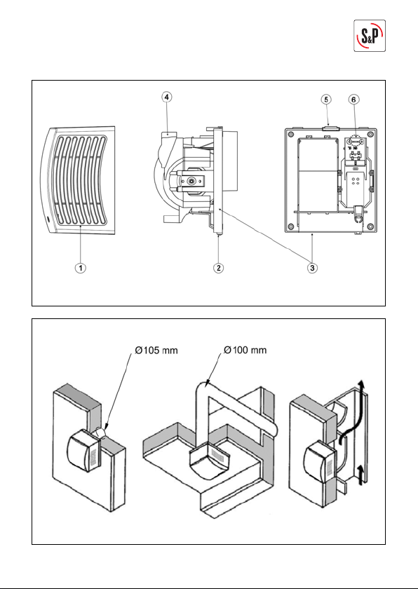
Fig. 1
Fig. 2
3
Page 3

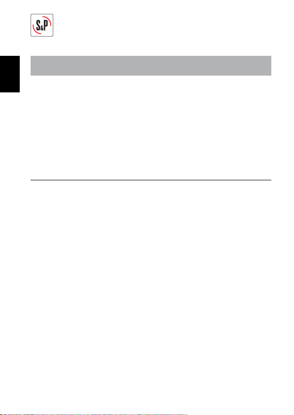
Fig. 3
Fig. 4
N
L
N
L
N
L
-
+
t
Fig. 5
4
Page 4
N
L
Fig. 6
N
L
-
+
-
+
t
%RH
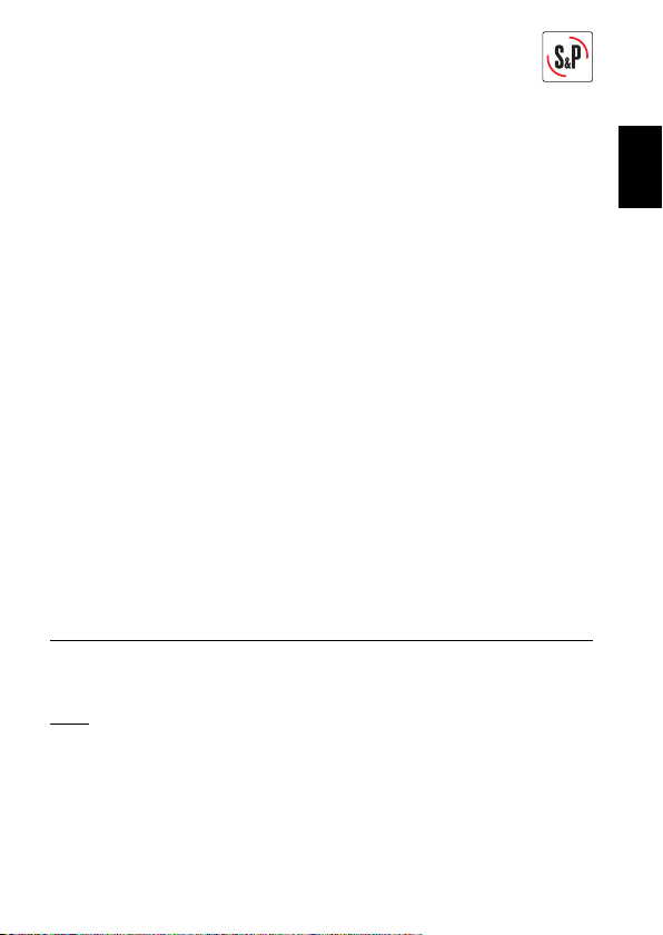
Fig. 7
N
L
Fig. 8
Fig. 6
Fig. 7
Fig. 8
5
Page 5
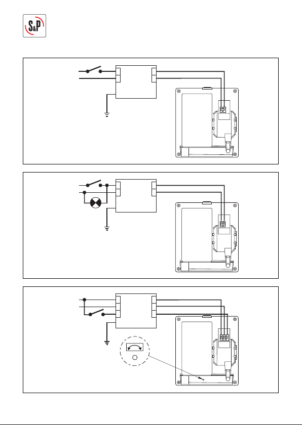
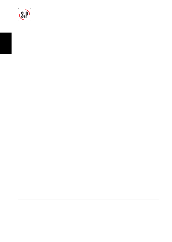
Fig. 9
N
L
N
L
N
L
230V
~50Hz
12V
~50Hz
CT-45/12
Fig. 10
N
L
N
L
N
L
230V
~50Hz
12V
~50Hz
CT-45/12
-
+
t
Fig. 11
N
L
N
L
N
L
230V
~50Hz
12V
~50Hz
Ls Ls
CT-45/12
6
Fig. 9
Fig. 10
Fig. 11
Page 6
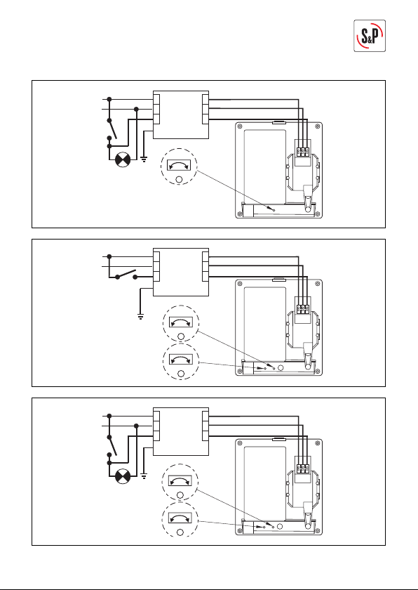
Fig. 12
-
+
t
N
L
N
L
N
L
230V
~50Hz
12V
~50Hz
Ls Ls
CT-45/12
Fig. 13
t
N
L
N
L
N
L
230V
~50Hz
12V
~50Hz
Ls Ls
CT-45/12
%RH
-
+
-
+
Fig. 14
N
L
N
L
230V
~50Hz
12V
~50Hz
Ls Ls
CT-45/12
t
-
+
-
+
%RH
N
L
Fig. 12
Fig. 13
Fig. 14
7
Page 7
ESPAÑOL
ESPAÑOL
Los extractores de la serie EB han sido fabricados bajo rigurosas normas de
producción y control de calidad como la ISO 9001. Todos los componentes han
sido verifi cados; todos los aparatos han sido probados a fi nal del montaje.
Antes de instalar y poner en funcionamiento este producto, lea atentamente el
presente libro de instrucciones pues contiene indicaciones importantes para su
seguridad y la de los usuarios durante la instalación, uso y mantenimiento de
este producto.
RECOMENDACIONES IMPORTANTES
• Compruebe el perfecto estado del aparato al desembalarlo ya que cualquier defecto de origen que presente, está amparado por la garantía S&P.Asimismo,
compruebe que el aparato es el que usted ha solicitado y que los datos que fi guran en la placa de instrucciones coincidan con sus necesidades.
• La instalación debe ser realizada por un profesional
califi cado.
• La instalación debe hacerse acorde con los reglamentos vigentes en cada país.
• Si el aparato funciona como extractor en una sala
donde haya instalada una caldera u otro tipo de sistema a combustión que necesita aire para su funcionamiento, comprobar que las entradas de aire de la
sala, sean correctamente dimensionadas.
• No se puede conectar la descarga del extractor a un
8
Page 8
conducto utilizado para evacuar los humos de aparatos alimentados a gas u otro combustible.
• Este aparato pueden utilizarlo niños con edad de
8 años y superior y personas físicas, sensoriales o
mentales reducidas o falta de experiencia y conocimiento, si se les ha dado la supervisión o formación
apropiadas respecto al uso del aparato de una manera segura y comprenden los peligros que implica.
• Los niños no deben jugar con el aparato.
• La limpieza y el mantenimiento a realizar por el usuario no deben realizarlos los niños sin supervisión.
• No introduzca ningún objeto a través de la rejilla de
protección.
• No extraer la reja frontal mientras el extractor cuando está en funcionamiento o rotación. El extractor
siempre tiene que funcionar con la reja frontal correctamente montada.
INSTALACIÓN
IMPORTANTE: Antes de proceder a la instalación i conexión del aparato, asegurarse de desconectar el suministro eléctrico.
Fig.1: 1- Reja 4- Tapa caja de bornes
2- Tornillo 5- Pasacable
3- Soporte 6- Muesca
El EB puede ser instalado en techo o pared, con descarga a conducto individual
o a un sistema de ventilación comunitario, (fi g.2).
Realizar un orifi cio en la pared o techo de diámetro 105 mm. Desenroscar el
tornillo (2) de sujeción de la reja (1).
ESPAÑOL
9
Page 9
ESPAÑOL
Si el montaje se hace con conducto individual, utilizar un conducto de diámetro
normalizado de 100 mm.
No se debe utilizar conductos de diámetro inferior. En caso de que el conducto
tenga que hacer un codo a la salida del extractor hacer lo con el radio más
grande posible.
Antes de fi jar el aparato, asegurarse que existe ninguna obstrucción al paso del
aire (conducto), que la compuerta situada en la boca de descarga del extractor
se abra fácilmente y que la turbina gira libremente.
Fijar el soporte (3) a la pared con los 4 tacos y tornillos suministrados en el
embalaje.
Desenroscar los tornillos de la tapa caja de bornes (4) para acceder a la fi cha
de conexiones.
Efectuar la conexión eléctrica tal como se indica a continuación.
CONEXIÓN ELÉCTRICA
El EB es un extractor preparado para alimentarse de una red monofásica, con
la tensión y la frecuencia que se indican en la placa de características situada
en el aparato.
Los extractores de la serie EB son de clase II (doble aislamiento eléctrico) y los
modelos EB 12V son clase III, por lo cual no precisan toma de tierra.
Nota: Los transformadores CT-45/12 utilizados para los modelos EB 12V, requieren de conexión a la toma de tierra.
En la instalación eléctrica deberá haber un interruptor omnipolar con una abertura entre contactos de al menos 3 mm.
El cable eléctrico puede introducirse en el EB sea por la muesca (6) si el cable
viene empotrado, sea por el pasacable (5) si la instalación es con cable visto.
Una vez introducido el cable realizar la conexión eléctrica a la fi cha de conexión
según el modelo de EB. Volver a montar la tapa de la caja de bornes (4), la reja
(1) y apretar el tornillo (2).
EB MODELOS S
Para estos modelos seguir los esquemas:
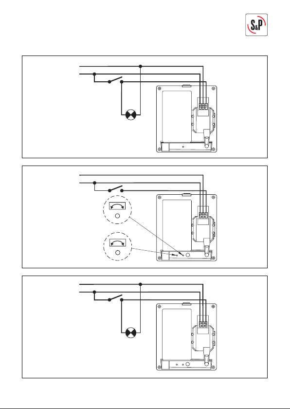
Fig. 3: Puesta en marcha del extractor con un interruptor independiente.
Fig. 4: Puesta en marcha del extractor con el mismo interruptor que el de la
luz.
10
Page 10
EB MODELOS S (12V~50Hz)
Estos modelos tienen que instalarse con un transformador CT 45/12.
Fig. 9: Conexión del transformador y el extractor a través de un interruptor
independiente.
Fig. 10: Conexión del transformador y el extractor a través del mismo inte-
rruptor de la luz.
EB MODELOS T
Modelos equipados con una temporización ajustable entre 1 y 30 minutos. La
temporización permite que el aparato siga funcionando el tiempo determinado
por la temporización, después que el interruptor haya sido cerrado.
El esquema fi g.5 muestra como conectar el aparato con temporización para que
se ponga en marcha con un interruptor independiente.
El esquema fi g.6 muestra como conectar el aparato con temporización para que
se ponga en marcha con el mismo interruptor que la luz.
Para ajustar esta temporización, girar el potenciómetro situado en la parte inferior del aparto (fi g.6) con un pequeño destornillador:
• Para aumentar el tiempo de temporización girar en el sentido horario (CW).
• Para disminuir el tiempo de temporización girar en el sentido anti-horario
(CCW).
EB MODELOS T (12V~50Hz)
Estos modelos tienen que instalarse con un transformador CT 45/12.
Fig. 11: Conexión del transformador y el extractor a través de un interruptor
independiente.
Fig. 12: Conexión del transformador y el extractor a través del mismo inte-
rruptor de la luz.
EB MODELOS HT
Los modelos HT son equipados con una temporización ajustable y un higrostato
electrónico regulable entre el 60 y el 90% RH (% humedad relativa). Las dos
funciones, temporización y control de humedad, son independientes.
ESPAÑOL
11
Page 11
ESPAÑOL
Los ajustes se efectúan por medio de los potenciómetros que se hallan en la
parte inferior de los extractores y que son accesibles después de desmontar
la reja (fi g.7).
Para ajustar la temporización, girar el potenciómetro de la izquierda con un
pequeño destornillador:
• Para aumentar el tiempo de temporización girar en el sentido horario (CW).
• Para disminuir el tiempo de temporización girar en el sentido anti-horario
(CCW).
Para ajustar el valor de humedad relativa encima del cual el aparato se pondrá
en marcha, girar el potenciómetro de la derecha situado en la parte inferior del
aparto, con un pequeño destornillador.
Funcionamiento
La temporización funciona cuando se cierra el interruptor que pilota el EB (interruptor independiente o interruptor de la luz).
Gracias al higrostato, el aparato se pone en marcha automáticamente cuando el
nivel de humedad es superior al valor ajustado con el potenciómetro.
Del mismo modo, se para cuando el nivel de humedad sea de nuevo inferior al
valor seleccionado.
El esquema fi g.7 muestra como conectar el aparato con temporización y higrostato con un interruptor independiente.
El esquema fi g.8 muestra como conectar el aparato con temporización y higrostato, con el mismo interruptor que la luz.
EB MODELOS HT (12V~50Hz)
Estos modelos tienen que instalarse con un transformador CT 45/12.
Fig. 13: Conexión del transformador y el extractor a través de un interruptor
independiente.
Fig. 14: Conexión del transformador y el extractor a través del mismo inte-
rruptor de la luz.
MANTENIMIENTO
IMPORTANTE: Antes de realizar cualquier operación de mantenimiento, asegúrese que el aparato está desconectado de la red eléctrica.
Sólo es necesaria una limpieza periódica del extractor con un paño impregnado
de detergente suave.
12
Page 12
ASISTENCIA TÉCNICA
La extensa red de Servicios Ofi ciales S&P garantiza una adecuada asistencia
técnica. En caso de observar alguna anomalía en el aparato, rogamos se ponga
en contacto con cualquiera de los servicios ofi ciales mencionados, donde será
debidamente atendido. Cualquier manipulación efectuada por personas ajenas
a los Servicios Ofi ciales S&P nos obligaría a cancelar su garantía.
Para aclarar cualquier duda con respecto a los productos S&P diríjase a la Red
de Servicios Post Venta si es en territorio español, o a su distribuidor habitual en el resto del mundo. Para su localización puede consultar la página WEB
www.solerpalau.com
RECICLAJE
La normativa de la CEE y el compromiso que debemos adquirir con
las futuras generaciones, nos obligan al reciclado de materiales,
le rogamos que no olvide depositar todos los elementos sobrantes
del embalaje en los correspondientes contenedores de reciclaje, así
como de llevar los aparatos sustituidos al Gestor de Residuos más
próximo.
S&P se reserva el derecho de modifi caciones sin previo aviso.
ESPAÑOL
13
Page 13
ENGLISH
The EB range extractors have been manufactured to the rigorous standards of
ENGLISH
production and quality as laid down by the international Quality Standards ISO
9001. All the components have been checked and all the fi nal products have
been tested at the end of the manufacturing process.
Please read this instructions booklet carefully before installing or starting up
the product. It contains important information on personal and user safety measures to be followed while installing, using and carrying out maintenance work
on the equipment.
IMPORTANT INFORMATION
• Check that the apparatus is in perfect condition whi-
le unpacking. Any fault or damage caused in origin is
covered by the S&P guarantee. Please make sure that
the apparatus coincides with the product you have
ordered and that the details on the instructions plate
fulfi l your necessities.
• Installation must only be carried out by qualifi ed per-
sons.
• Make sure that the installation complies with each
country’s current mechanical and electrical norms.
• If a ventilator is going to be installed to extract air
from premises where a boiler or other combustion
apparatus are installed, make sure that the building
has suffi cient air intakes to assure adequate combus-
tion.
14
Page 14
• The extractor outlet must not be connected to a duct
used to exhaust smoke or fumes from any appliance
that uses gas or any other type of fuel.
• This appliance can be used by children aged from 8
years and above and persons with reduced physical,
sensory or mental capabilities or lack of experienceand knowledge if they have been given supervision
or instruction concerning use of the appliance in a
safe way and understand the hazards involved.
• Children should not play with the product.
• Cleaning and user maintenance shall not be made by
children without supervision.
• Do not introduce any object through the protective grille.
• Do not remove the front grille while the fan is in operation or rotation. The extractor must always operate
with properly mounted front grille.
INSTALLATION
IMPORTANT: Before installing and wiring the EB, ensure that the main supply
is disconnected.
Fig.1: 1- Protection grille 4- Connection terminals cover
2- Fixing screw 5- Cable entry
3- Fan support 6- Slot
The EB can be wall or ceiling mounted, and it can discharge directly to the outside or through a duct (individual or common duct, Fig. 2).
The hole to be made in the wall or the ceiling must be 105 mm in diameter.
Loosen the screw (2) fi xing the protection grille (1).
ENGLISH
15
Page 15
If the installation is made to an individual ducting, use standard ducting of 100
mm diameter. Smaller diameter must not be used. If it is necessary to bend the
duct at the discharge of the fan, make the radius as large as possible.
Before fi xing the fan support (3), ensure that there are no obstructions to the
airfl ow, that the shutter mounted at the fan discharge opens easily and that the
ENGLISH
impeller turns freely.
Fix the fan support to the wall with the 4 plugs and screws supplied in the packaging. Loosen the screws of cover (4) to gain access to the connection terminals. Connect the electrical wiring as follows.
ELECTRICAL CONNECTION
The EB is an extractor designed for a single phase supply, with voltage and
frequency as indicated on the rating plate of the unit. The EB models are made
Class II (double electrical insulation) and the EB 12V are made Class III and
therefore they do not need an earth connection.
IMPORTANT: The safety isolating transformers CT-45/12 used with EB 12V
must be earth connected.
The electrical installation must include a double pole switch with a contact clearance of at least 3 mm.
The electrical cable must be introduced to the EB through the slot (6) if the wire
is within the wall or through the cable entry (5 if the installation is made with a
surface mounted cable.
Once the cable has been introduced, proceed to the appropriate electrical wiring
depending on the EB model.
EB MODELS S
For these models use the following diagrams:
Fig. 3: To switch the fan through an independent switch.
Fig. 4: Switching the extractor through the light switch.
EB MODELS S (12V~50Hz)
For these models use the CT-45/12 safety isolating transformer:
Fig. 9: To switch the transformer and the extractor through an independent switch.
Fig. 10: Switching the transformer and the extractor through the light switch.
16
Page 16
EB MODELS T
Models fi tted with an adjustable timer, variable between 1 and 30 minutes. The
timer enables the extractor to continue running during the time delay, after the
supply has been switched off.
The diagram on Fig. 5 shows how to connect a unit fi tted with timer using an
independent switch.
The diagram on Fig. 6 shows how to connect a unit fi tted with timer using the
light switch.
To adjust the timer, turn the potentiometer in the lower part of the fan with a
small screwdriver:
• To increase the time delay turn it Clockwise (CW).
• To decrease the time delay turn it Counter Clockwise (CCW).
EB MODELS T (12V~50Hz)
For these models use the CT-45/12 safety isolating transformer:
Fig. 11: To switch the transformer and the extractor through an independent
switch.
Fig. 12: Switching the transformer and the extractor through the light switch.
EB MODELS HT
This model is provided with an electronic hygrostat which can be adjusted from
60 to 90 % RH (% relative humidity).
The two functions, timer and humidity control, are independent The adjustments
are carried out with the potentiometer in the lower part of the appliance (fi g.7).
To adjust the timer, turn the right potentiometer with a small screwdriver:
• To increase the time delay turn it Clockwise (CW).
• To decrease the time delay turn it Counter Clockwise (CCW).
To adjust the humidity level above which the fan will operate automatically, turn
the left potentiometer with a small screwdriver.
Operation
The timer will operate when the Switch (independent switch or light switch) is
switched off.
The hygrostat causes the extractor to operate automatically when the humidity
ENGLISH
17
Page 17
level in the room is higher than the level selected with the potentiometer.
Likewise, the extractor will stop automatically when the humidity level drops
below the selected level.
The diagram on fi g.7 shows how to connect the unit through an independent
switch.
ENGLISH
The diagram on fi g.8 shows how to connect the unit through the light switch.
EB MODELS HT (12V~50Hz)
For these models use the CT-45/12 safety isolating transformer:
Fig. 13: To switch the transformer and the extractor through an independent
switch.
Fig. 14: Switching the transformer and the extractor through the light switch.
MAINTENANCE
IMPORTANT: Before manipulating the ventilator, make sure it is disconnected
from the mains supply even if it has previously been switched off. Prevent the
possibility of anyone else connecting it while it is being manipulated. The extractor needs only a periodical cleaning using a cloth lightly impregnated with
a soft detergent.
AFTER SALES SERVICE
The extensive network of S&P Offi cial Services guarantees good technical assistance all over Spain. If you observe any anomalies in the convector, please
contact any of the above mentioned Services, where you can get the correct
advice. Any modifi cation that is not strictly necessary for the installation of the
device and carried out by persons outside of the S&P Offi cial Services will invalidate the guarantee.
For any queries regarding the S&P Products go to the S&P After Sales Service
network if is Spanish territory or your dealer in the world. For the nearest location you can consult the webpage: www.solerpalau.com.
18
Page 18

RECYCLING
EEC Standards, together with the responsibility we should assume
with future generations in mind, oblige us to recycle all the materials
we can. Therefore, please deposit all left-over material and packaging in their corresponding recycling containers and hand in the replaced machines to the nearest handler of this type of waste product.
S&P reserves the right to alter specifi cations without notice.
ENGLISH
19
Page 19

FRANÇAIS
Les aérateurs de la série EB ont été fabriqués en respectant de rigoureuses
normes de fabrication et de contrôle qualité (ISO 9001). Tous les composants
ont été vérifi és; tous les appareils ont été testés en fi n de montage.
Avant d’installer et de mettre en marche ce produit, lire attentivement ces instructions car elles contiennent des informations importantes quant à votre sé-
FRANÇAIS
curité et celle des utilisateurs, pendant l’installation, l’utilisation et l’entretient
de ce produit.
RECOMMANDATIONS IMPORTANTES
• Dès réception, vérifi er le parfait état de l’appareil
étant donné que tout défaut d’origine est couvert par
la garantie S&P. De même, vérifi er que le type du ventilateur soit conforme à celui commandé et que les
caractéristiques inscrites sur la plaque signalétique
soient compatibles avec celles de l’installation.
• L’installation doit être effectuée par un professionnel
qualifi é.
• S’assurer que l’installation répond aux réglemen-
tations mécaniques et électrotechniques en vigueur
dans chaque pays.
• Si le ventilateur doit être installé dans un local équipé
d’une chaudière ou d’un autre type d’appareil à combustion, s’assurer que les entrées d’air dans le local
sont suffi samment dimensionnées pour garantir une
combustion correcte.
20
Page 20

• Ne pas raccorder l’aérateur à un conduit utilisé pour
évacuer les fumées d’appareils alimentés au gaz ou
autre combustible.
• Cet appareil peut être utilisé par des enfants âgés de
8 ans et plus, Cet appareil n’est pas prévu pour être
utilisé par des personnes (y compris les enfants) dont
les capacités physiques, sensorielles ou mentales
sont réduites ou des personnes dénuées d’expérience ou de connaissance, sauf si elles ont pu bénéfi cier,
par l’intermédiaire d’une personne responsable de
leur sécurité, d’une surveillance ou d’instructions
préalables concernant l’utilisation de l’appareil.
• Les enfants ne doivent pas jouer avec l’appareil.
• Les enfants ne doivent ni nettoyer l’appareil ni s’occuper de son entretien sans surveillance.
• Ne pas introduire d’objet au travers de la grille de
protection.
• Ne pas enlever la grille frontale lorsque l’extracteur
est en fonctionnement ou en mouvement. Le ventilateur doit toujours fonctionner avec la grille frontale
correctement installée.
INSTALLATION
IMPORTANT: Avant d’installer et de raccorder l’EDM, s’assurer que le câble
d’alimentation soit déconnecté du réseau électrique.
Schéma fi g.1: 1 - Grille de protection 4- Couvercle de boite à bornes
2 - Vis de fi xation 5- Passe-câbles
3- Support 6- Passe-câble arrière
FRANÇAIS
21
Page 21

L’EB peut être installé soit au mur soit au plafond, en rejet d’air directement
vers l’extérieur ou en conduit individuel ou collectif (fi g.2).
Pratiquer, dans le mur ou le plafond, une ouverture de diamètre 105 mm.
Dévisser la vis de maintient (2) de la grille de protection (1).
Si le montage est réalisé avec un conduit individuel, utiliser un conduit de
diamètre normalisé de 100 mm.
Ne pas utiliser de conduit ayant un diamètre inférieur à 100 mm.
S’il est prévu de faire un coude au souffl age du ventilateur, le faire le plus arrondi possible.
FRANÇAIS
S’assurer qu’il n’existe dans le conduit aucune obstruction au passage de l’air,
que le volet de surpression situé dans la bouche de souffl age s’ouvre facilement
et que la turbine tourne librement.
Placer le support (3) contre le mur ou au plafond et le fi xer à l’aide des 4 vis et
chevilles fournies dans l’emballage.
Dévisser les vis de maintien du couvercle de boite à bornes (4) pour pouvoir
accéder au bornier.
Raccorder le câble électrique comme indiqué ci-après.
RACCORDEMENT ÉLECTRIQUE
L’EB est un aérateur prévu pour être raccordé à un réseau monophasé dont
la tension et la fréquence sont indiquées sur la plaque signalétique placée à
l’arrière de l’appareil.
Les aérateurs EB sont Classe II (double isolation) et les aérateurs EB 12V sont
classe III ce qui fait qu’il n’est pas nécessaire de les raccorder à la terre.
IMPORTANT: Le transformateur de sécurité CT-45/12 utilisé avec les EB 12V
doit être raccordé à la terre.
Pour le raccordement, prévoir dans l’installation électrique un interrupteur
ayant une ouverture entre contacts d’au moins 3 mm.
Le câble électrique peut être introduit dans l’EB soit par le passe-câble à
l’arrière de l’appareil (6), soit par le passecâble (5).
Une fois le câble introduit dans l’EB réaliser le branchement au bornier suivant
la version de l’EB.
Remonter le couvercle de boite à bornes (4), la grille de protection (1) et serrer
la vis de fi xation (2).
22
Page 22

EB VERSIONS S
Pour ces modèles sont proposés deux schémas:
Fig.3: Mise en marche de l’EB par un interrupteur indépendant.
Fig.4: Mise en marche de l’EB par le même interrupteur que celui de la lumière.
EB VERSIONS S (12V~50Hz)
Ces modèles doivent être alimentés par le transformateur de sécurité CT-45/12:
Fig.9: Mise en marche du transformateur et de l’aérateur par un interrup-
teur indépendant.
Fig.10: Mise en marche du transformateur et de l’aérateur par le même inte-
rrupteur que celui de la lumière.
EB VERSIONS T
Modèles équipés d’une temporisation réglable entre 1 et 30 minutes.
La temporisation permet à l’appareil de continuer à fonctionner, le temps déterminé par la temporisation, après que l’interrupteur ait été fermé.
Le schéma de câblage fi g.5 montre comment commander l’appareil temporisé
avec un interrupteur indépendant Le schéma de câblage fi g.6 montre comment,
avec le même interrupteur, commander la lumière dans la pièce et la mise en
route de l’EB temporisé.
Pour régler cette temporisation agir sur le potentiomètre situé en partie inférieure de l’appareil (fi g.6), avec un petit tournevis:
• Pour augmenter le temps de fonctionnement tourner dans le sens horaire
(CW).
• Pour diminuer le temps de fonctionnement, tourner dans le sens anti-horaire (CCW).
EB VERSIONS T (12V~50Hz)
Ces modèles doivent être alimentés par le transformateur de sécurité CT-45/12:
Fig. 11: Mise en marche du transformateur et de l’aérateur par un interrup-
teur indépendant.
Fig. 12: Mise en marche du transformateur et de l’aérateur par le même inte-
rrupteur que celui de la lumière.
FRANÇAIS
23
Page 23

EB VERSIONS HT
Les versions HT sont équipées d’une temporisation réglable entre 1 et 30 minutes ainsi que d’un hygrostat électronique réglable entre 60 et 90 %RH (% d’humidité relative).
Les deux fonctions, temporisation et control de l’humidité sont indépendantes
l’une de l’autre.
Les réglages s’effectuent à l’aide d’un petit tournevis, en agissant sur les deux
potentiomètres situés en partie inférieure de l’EB et accessibles après avoir
FRANÇAIS
retiré la grille de protection (fi g.7).
Pour régler la temporisation tourner le potentiomètre de droite:
• Pour augmenter le temps de fonctionnement tourner dans le sens horaire
(CW).
• Pour diminuer le temps de fonctionnement, tourner dans le sens anti-horai-
re (CCW).
Pour régler la valeur d’humidité relative au-dessus de laquelle l’appareil se mettra automatiquement en marche, tourner le potentiomètre de gauche.
Fonctionnement
La temporisation fonctionnera dès que l’interrupteur pilotant l’appareil (indépendant ou de la lumière) sera fermé.
Grace à l’hygrostat, l’aérateur se mettra automatiquement en marche quand le
niveau d’humidité dans la pièce sera supérieur à la valeur préréglée.
De même, l’aérateur s’arrêtera automatiquement quand le niveau d’humidité
dans la pièce sera de nouveau inférieur à la valeur préréglée.
Le schéma fi g.7 montre comment raccorder l’appareil à un interrupteur indépendant.
Le schéma fi g.8 montre comment raccorder l’appareil au même interrupteur
que celui de la lumière.
EB VERSIONS HT (12V~50Hz)
Ces modèles doivent être alimentés par le transformateur de sécurité CT-45/12:
Fig.13: Mise en marche du transformateur et de l’aérateur par un interrup-
teur indépendant.
Fig.14: Mise en marche du transformateur et de l’aérateur par le même inte-
rrupteur que celui de la lumière.
24
Page 24

ENTRETIEN
IMPORTANT: Avant de manipuler le ventilateur, s’assurer qu’il est débranché du
réseau électrique, même s’il est arrêté, et que personne ne puisse le mettre en
marche pendant l’opération Nettoyer régulièrement l’aérateur avec un chiffon
imprégné d’un détergent doux.
Nous vous conseillons de ne pas démonter d’autres pièces que celles indiquées;
toutes autres manipulations pourraient entraîner la suppression de la garantie.
En cas de problème avec l’extracteur se mettre en contact avec son distributeur.
ASSISTANCE TECHNIQUE
En cas d’anomalie dans le fonctionnement de l’appareil, contacter votre distributeur. Toute manipulation, qui n’est pas strictement nécessaire à l’installation
de l’appareil, réalisée par des personnes non qualifi ées, nous obligerait à annuler la garantie.
RECYCLAGE
La norme de la CEE et l’engagement que nous devons prendre par
rapport aux nouvelles générations nous obligent à recycler les matériaux; nous vous prions donc de ne pas oublier de déposer tous les
éléments restants de l’emballage dans les containers de recyclage
correspondants, et d’emporter les appareils usagés au Point de Recyclage le plus proche.
S&P se réserve le droit de modifi er ces instructions sans préavis.
25
FRANÇAIS
Page 25

DEUTSCH
Die Herstellung von Ventilatoren der Serie EB unterliegt den strengen Normen
für Fertigungs- und Qualitätskontrolle ISO 9001. Alle Bauteile wurden einzeln
geprüft; alle Geräte werden nach Fertigstellung einer Endkontrolle unterzogen.
Vor dem Einbau und der Inbetriebnahme lesen Sie bitte diese Betriebsanleitung
aufmerksam durch. Sie enthält wichtige Hinweise für die Sicherheit während
Montage, Inbetriebsetzung und Instandhaltung dieses Produktes.
Nach der Installation und Inbetriebnahme übergeben Sie dieses Anweisungshandbuch bitte dem Betreiber.
DEUTSCH
WICHTIGE SICHERHEITSHINWEISE
• Bitte prüfen Sie das Gerät nach Erhalt auf einwan-
dfreien Zustand und Funktion. Kontrollieren Sie an
Hand des Typenschildes, ob Modell, Ausführung und
technische Daten mit Ihrer Bestellung übereinstim-
men.
• Die Installation muss grundsätzlich durch einen qua-
lifi zierten Fachbetrieb erfolgen.
• Stellen Sie sicher, dass die Installation den mecha-
nischen und elektrischen nationalen.
• Wenn das Produkt in einem Raum zusammen mit
schornsteinabhängigen Feuerungen (Heizkessel
usw.) betrieben wird, muss auf jeden Fall für ausrei-
chende Zuluft gesorgt werden.
• Der Ausblasstutzen des Ventilators darf nicht an einen
Schacht angeschlossen werden, der zum Rauchabzug
26
Page 26

von Gas oder Brennstoff betriebenen Geräten benutzt
wird.
• Dieses Gerät darf nur nach einer entsprechenden Unterweisung über eine sichere Handhabung von Kindern über 8 Jahre und körperlich bzw. geistig behinderten Personen benutzt werden.
• Kinder dürfen nicht mit diesem Gerät spielen.
• Wartung und Reinigung sollte nicht von unaufbesichtigten Kindern durchgeführt werden.
• Stecken Sie keine Gegenstände durch das Schutzgitter.
• Entfernen Sie das Schutzgitter nicht, während der Ventilator in betreib ist oder noch dreht. Betreiben Sie den
Ventilator nur mit korrekt montiertem Schutzgitter.
MONTAGE
ACHTUNG: Bevor der Lüfter installiert und angeschlossen wird, ist sicherzustellen, daß das Gerät vom Netz getrennt ist.
Abb. 1 und 2: 1 - Lüftungsgitter 4 - Klemmenkastendeckel
2 - Schraube 5 - Seitliche Kabeldurchführung
3 - Halterung 6 - Hintere Kabeldurchführung
Der Lüfter kann an der Decke oder an der Wand installiert werden. Dabei kann
er sowohl an einem einzelnen Schacht als auch an ein zentrales Lüftungssystem angeschlossen werden (Abb. 2).
An der Wand oder an der Decke ein Loch mit 105 mm NW anbringen.
Die Befestigungsschraube (2) des Lüftungsgitters (1) lösen.
Wird der Lüfter an einen Schacht angeschlossen, ist eine Nennweite von 100
mm. Schächte mit geringerer Nennweite dürfen nicht benutzt werden. Soll an
Ausblasseite des Lüfters ein Schacht mit einem Bogen angeschlossen werden,
ist diese mit dem größtmöglichen Radius auszuführen.
27
DEUTSCH
Page 27

Vor der Befestigung des Geräts ist der Schacht auf eventuelle Hindernisse zu
überprüfen. Weiters ist sicherzustellen, daß die Klappe des Ausblasstutzens
sich leicht öffnet und die Leichtgängkeit des Laufrades zu überprüfen.
Die Halterung (3) mit den 4 Schrauben und Dübeln, die in der Verpackung mitgeliefert werden, befestigen.
Die Schrauben des Klemmenkastendeckels
(4) lösen, damit die Anschlußleiste erreicht werden kann.
Den elektrischen Anschluß wie weiter unten beschrieben durchführen.
ELEKTRISCHER ANSCHLUSS
Die EB-Modelle sind für den Anschluß an ein Wechselstromnetz vorgesehen. Es
DEUTSCH
ist sicherzustellen, daß die Spannungs- und Frequenzwerte des Stromnetzes,
an das der Lüfter angeschlossen wird, mit den auf dem Typenschild des Gerätes
angegebenen Werten übereinstimmen.
Die Ventilatoren der Serie EB (230V) haben die Schutzklasse II (doppelte Isolierung zwischen Netzstromkreis und Ausgangsspannung) und die Modelle der
Serie EB mit 12V haben Schutzklasse III. Deswegen wird ein Anschluss an den
Schutzleiter (Erde) nicht benötigt.
Bemerkung: Die Transformatoren CT-45/12 die für das Modell EB 12V eingesetzt werden müssen an den Schutzleiter angeschlossen werden.
Bei der Installation ist ein Trennschalter mit einer Trenn-strecke von mind. 3
mm pro Pol vorzusehen (allpoliger Schutz).
Die Installation kann mit einem eingemauertem oder mit einem offen geführten
Kabel durchgeführt werden. Im ersten Fall ist zur Einführung des Kabels die
hintere Kabeldurchführung (6) zu öffnen, im zweiten Fall ist es durch die seitliche Kabeldurchführung (5) zu führen.
Darauf das Kabel an die Klemmenleiste anschließen. Beachten Sie dabei bitte den dem jeweiligen EB-Modell entsprechenden Schaltplan. Den Deckel des
Klemmenkastens (4) wieder anbringen, das Schutzgitter (1) aufsetzen und die
Schraube (2) anziehen.
EB MODELLE S
Bei diesen Modellen ist nach folgenden Schaltplänen vorzugehen:
Abb.3 Separater Schalter für die Inbetriebnahme des Ventilators
Abb.4 Inbetriebnahme des Ventilators mit dem Lichtschalter.
28
Page 28

EB MODELLE S (12V~50Hz)
Diese Modelle müssen mit einem Sicherheitstransformator CT 45/12 nach DIN
VDE 0570-2-6 bzw.
EN61558-2-6 installiert werden.
Abb.9 Anschlussschema des Transformators und des Ventilators an einen
separaten Schalter.
Abb.10 Anschlussschema des Transformator und des Lüfters an den Lichts-
chalter.
EB MODELLE T
Mit zwischen 1 und 30 Minuten einstellbarem Nachlauf ausgestattetes Modell.
Wird der Ventilator ausgeschaltet, läuft der Ventilator für die eingestellte Nachlaufzeit weiter.
In Abb. 5 ist der Schaltplan für Geräte mit Nachlaufrelais und Inbetriebnahme
über einen separaten Schalter dargestellt.
In Abb. 6 ist der Schaltplan für Geräte mit Nachlaufrelais und Inbetriebnahme
über den Lichtschalter dargestellt.
Die Nachlaufzeit an dem an der Unterseite des Geräts angebrachten Potentiometer (Abb. 6) mit einem kleinen Schraubenzieher einstellen.
• Zur Erhöhung der Nachlaufzeit das Potentiometer im Uhrzeigersinn (CW)
drehen.
• Zur Verringerung der Nachlaufzeit das Potentiometer entgegen den Uhrzeigersinn (CCW) drehen.
EB MODELLE T (12V~50Hz)
Diese Modelle müssen mit einem Sicherheitstransformator CT 45/12 nach DIN
VDE 0570-2-6 bzw. EN61558-2-6 installiert werden.
Abb.11 Anschlussschema des Transformators und des Ventilators an einen
separaten Schalter.
Abb.12 Anschlussschema des Transformator und des Lüfters an den Lichts-
chalter.
DEUTSCH
29
Page 29

EB MODELLE HT
Die Modelle HT sind mit einem einstellbaren Nachlaufrelais und mit einem elektronisch
zwischen 60 und 90% relativer Feuchte einstellbaren Hygrostat ausgestattet.
Die beiden Funktionen, Nachlauf und Feuchtigkeitsüberwachung, werden unabhängig voneinander durchgeführt.
Die Nachlaufzeit und die relative Feuchte werden über zwei an der Unterseite
des Lüfters angebrachte Potentiometer eingestellt.
Diese sind nach Abnahme des Schutzgitters zugänglich (Abb. 7).
Die Nachlaufzeit kann am linken Potentiometer mit einem kleinen Schraubenzieher eingestellt werden.
• Zur Erhöhung der Nachlaufzeit das Potentiometer im Uhrzeigersinn (CW)
DEUTSCH
drehen.
• Zur Verringerung der Nachlaufzeit das Potentiometer entgegen den Uhrzei-
gersinn (CCW) drehen.
Der relative Feuchtegrad, ab dem das Gerät in Betrieb genommen werden soll,
kann am rechten, an der Unterseite des Gerätes angebrachten Potentiometer
mit einem Schraubenzieher eingestellt werden.
Betrieb
Der Nachlauf wird eingeschaltet, sobald das Gerät über den separaten oder
den Lichtschalter ausgeschaltet wird. Das Gerät wird über den Hygrostat automatisch in Betrieb genommen, sobald die relative Luftfeuchtigkeit des Raumes
den mit dem Potentiometer vorgegebenen Wert überschreitet. Das Gerät wird
automatisch abgeschaltet, wenn die relative Luftfeuchtigkeit wieder unter den
eingestellten Wert fällt.
In Abb. 7 ist der Schaltplan für Geräte mit Nachlaufrelais und Hygrostat, die
über einen separaten Schalter in Gang gesetzt werden, dargestellt.
In Abb. 8 ist der Schaltplan für Geräte mit Nachlaufrelais und Hygrostat, die
über den Lichtschalter in Gang gesetzt werden, dargestellt.
EB MODELLE HT (12V~50Hz)
Diese Modelle müssen mit einem Sicherheitstransformator CT 45/12 nach DIN
VDE 0570-2-6 bzw.
EN61558-2-6 installiert werden.
Abb.13 Anschlussschema des Transformators und des Ventilators an einen
separaten Schalter.
30
Page 30

Abb.14 Anschlussschema des Transformator und des Lüfters an den Lichts-
chalter.
INSTANDHALTUNG
ACHTUNG: Wartungsarbeiten dürfen ausschließlich durch ausgebildetes Fachpersonal und nach den jeweils geltenden nationalen Vorschriften durchgeführt werden. Zur Instandhaltung ist nur eine regelmäßige Reinigung des Gerätes notwendig. Vor der Reinigung ist das Gerät vom Netz zu trennen.
Ein handelsübliches Reinigungsmittel und einen Putzlappen benutzen.
INSTANDHALTUNG
Wartungsarbeiten dürfen ausschließlich durch ausgebildetes Fachpersonal und
nach den jeweils geltenden nationalen Vorschriften durchgeführt werden. Zur
Instandhaltung ist nur eine regelmäßige Reinigung des Gerätes notwendig. Vor
der Reinigung ist das Gerät vom Netz zu trennen. Ein handelsübliches nicht
aggressives Reinigungsmittel und einen Putzlappen benutzen.
RECYCLING
Die CEE-Regelungen und unsere Verantwortung zukünftigen Generationen gegenüber verpfl ichten uns zum Materialrecycling. Deshalb bitten wir Sie, sämtliche Verpackungsreste in die entsprechenden Trenn-Müllbehälter zu entsorgen und die defekten Altgeräte bei
einem geigneten Entsorgungsbetrieb abzugeben.
S&P behält sich das Recht auf technische Änderungen ohne vorherige Ankündigung vor.
DEUTSCH
31
Page 31

NEDERLAND
De afzuigventilatoren van de EB-reeks worden volgens strenge normen voor
productie en kwaliteitscontrole zoals de norm ISO 9001 geproduceerd. De werking van alle componenten is gecontroleerd. Bij het einde van het montageproces worden alle apparaten getest.
Wij verzoeken u voordat u over gaat tot de installatie en de inbedrijfstelling van
dit product deze handleiding aandachtig te lezen. Deze bevat belangrijke aanwijzingen voor uw eigen veiligheid en die van de gebruikers tijdens de installatie,
het gebruik en het onderhoud.
BELANGRIJKE INFORMATIE
NEDERLAND
• Controleer de goede staat van het apparaat bij het ui-
tpakken. Elk fabrieksmatig defect of defect tengevol-
ge van het transport valt onder de S&Pgarantie, meld
dit dan ook onmiddellijk aan uw leverancier. Contro-
leer ook of het apparaat daadwerkelijk overeenkomt
met het door u bestelde model, zie hiervoor het type-
plaatje.
• De installatie moet worden uitgevoerd door een er-
kende installteur.
• De installatie moet voldoen aan de ter plaatse gelden
normen op mechanisch en elektrisch installaties.
• Indien u een ventilator gaat installeren die lucht af-
voert uit een ruimte met een verbrandingsapparaat,
moet u controleren of er voldoende toevoer van verse
lucht is om een correcte verbranding te kunnen ga-
randeren.
32
Page 32

• De ventilator is geschikt voor het afvoeren van vervuilde lucht via een kanaal, zijnde geen gookgaskanaal.
• Dit apparaat kan worden gebruikt door kinderen in
de leeftijd van 8 jaar en hoger en personen met verminderde lichamelijke, zintuiglijke of geestelijke mogelijkheden of gebrek aan ervaring en kennis als ze
toezicht of instructie hebben gekregen betreffende
het gebruik van het toestel op een veilige manier en
begrijpen de gevaren.
• Het is verboden voor kinderen om met het toestel te
spelen.
• Schoonmaak en onderhoud mogen niet door kinderen
uitgevoerd worden zonder toezicht.
• Steek geen voorwerpen door het beschermrooster.
• Verwijder het beschermrooster niet wanneer de ventilator in werking is. De ventilator mag alleen gebruikt
worden wanneer het beschermrooster goed gemonteerd is.
INSTALLATIE
IMPORTANT: Controleer voordat u onderhoud gaat plegen altijd eerst of dit
apparaat is losgekoppeld van het elektriciteits net alvorens dit te openen of te
demonteren, zelfs als dit is uitgeschakeld.
Fig.1: 1- Beschermrooster 4- Aansluitbeschermkap
2- Bevestigingsschroef 5- Kabelinover
3- Ventilatorhuis 6- Achterinvoer
De ventilatoren uit deze EB serie zijn zo geconstrueerd dat deze in iedere positie
geplaast kunnen worden. De afvoer kan direct naar buiten, via een eigen kanaal
NEDERLAND
33
Page 33

of gemeenschappelijk kanaal geschieden (fi g.2). het ventilatiekanal dient 100 Ø
inwendig te zijn.
Na het losdraaien van de schroef (2) kunt u de beschermkap (1) verwijderen,
waarna u het ventilatorhuis op e juiste plaatstegen wand of plafond kunt monteren dmv de bijgeleverde schroeven en pluggen.
Er mag geen smallere buis toegepast worden dan 100 mm Ø inwending, daar dit
het functioneren van ingebouwde terugslagklep en/of de ventilator belemmerd.
Indien achter de ventilator een bocht geplaatst moet worden dient deze zo ver
mogelijk achter de ventilator te liggen.
ELEKTRISCHE AANSLUITING
Verwijder de afdekkap van de elektrische aansluitpunten en sluit de ventilator
aan volgens één van de volgende schema’s.
The EB models are made Class II (double electrical insulation) and the EB 12V
are made Class III and therefore they do not need an earth connection.
IMPORTANT: The safety isolating transformers CT-45/12 used with EB 12V
NEDERLAND
must be earth connected.
The electrical installation must include a double pole switch with a contact clearance of at least 3 mm.
Het invoeren van de kabel kan geschieden door de achterinvoer (6) of door de
kabelinover bovenop de ventilator.
MODELLEN EB-S
Aansluiting geschiedt volgens schema:
Fig. 3: voor schakeling met een separate schakelaar.
Fig. 4: voor schakeling in combinative met de lichtschakelaar.
MODELLEN EB-S (12V~50Hz)
For these models use the CT-45/12 safety isolating transformer:
Fig. 9: To switch the transformer and the extractor through an independent
switch.
Fig. 10: Switching the transformer and the extractor through the light switch.
34
Page 34

MODELLENS EB-T
Deze modellen zijn voorzien van een instelbare nalooptimer, welke instelbaar
is van enkele tot max. 30 min. Na het uitschakelen van de ventilator blijft deze
gedurende de ingestelde tijd nalopen.
Aansluiting geschiedt volgens schema:
Fig. 7: voor schakeling met een separate schakelaar.
Fig. 8: voor schakeling in combinative met de lichtschakelaar.
Voor het verlengen van de nalooptijd wordt de potentiometer met de klok (CW)
mee gedraaid.
Voor het verkoten van de nalooptijd wordt de potentiometer tegen de klok (CCW)
in gedraaid.
MODELLEN EB-T (12V~50Hz)
For these models use the CT-45/12 safety isolating transformer:
Fig. 11: To switch the transformer and the extractor through an independent
switch.
Fig. 12: Switching the transformer and the extractor through the light switch.
MODELLEN EB-HT
Modellen EB-HT Deze modellen zijn voorzien van een instelbare hygrostat voor
een vochtigheidnivo tussen 60 en 90% RV en een instelbare nalooptimer, welke
instelbaar is van enkele tot max. 30 min.
De werking van de ventilator via de ingebouwde hygrostaat is primair aan de
andere schakelaars, na het bereiken van de ingestelde RV waarde stopt de ventilator automatisch.
Na het uitschakelen van de ventiltor blijft deze gedurende de ingestelde tijd
nalopen.
Aansluiting geschiedt volgens schema:
Fig. 5: voor schakeling met een separate schakelaar.
Fig. 6: voor schakeling in combinative met de lichtschakelaar.
Voor het verlengen van de nalooptijd wordt de potentiometer met de klok (CW)
mee gedraaid.
Voor het verkoten van de nalooptijd wordt de potentiometer tegen de klok (CCW)
in gedraaid.
Het instellen van de relatieve vochtigheid (RV) wijst zich vanzelf.
35
NEDERLAND
Page 35

MODELLEN EB-HT (12V~50Hz)
For these models use the CT-45/12 safety isolating transformer:
Fig. 13: To switch the transformer and the extractor through an independent
switch.
Fig. 14: Switching the transformer and the extractor through the light switch.
ONDERHOUD
IMPORTANT: Controleer altijd eerst of dit apparaat is losgekoppeld van het elektriciteitsnet alvorens het te demonteren, zorg er ook voor dat niemand het kan
in werking stellen tijdens de onderhoudsbeurt.
De ventilator dient regelmatig gereinigd te worden. Dit kan geschieden met een
vochtige doek met een niet agressief ontvettings og reinigingsmiddel, daarbij
oplettend dat er geen water in de motor of het elektrische gedeelte kan komen.
NEDERLAND
SERVICE
We bevelen aan om het toestel niet te demonteren. Elke manipulatie van het
toestel heeft automatisch de annulering van de S&P-garantie voor gevolg.
Als u een abnormaal gedrag van het apparaat of de structuur vaststelt, trek
dan onmiddellijk de stekker uit het stopcontact. Breng het apparaat naar een
gekwalifi ceerde reparatiedienstomzo gevaarlijke situaties te voorkomen.
RECYCLING
De regelgeving van de EG en onze verplichtingen t.o.v. de komende
generaties verplichten ons materialen te recycleren. Wij verzoeken u
dringend de verpakkingsresten in de overeenkomstige recyclingcontainer te deponeren; de afgedankte apparaten moeten via de geëigende afvalverwerkingkanalen verwerkt te worden.
S&P behoudt zich het recht voor wijzigingen aan te brengen zonder voorafgaande waarschuwing.
36
Page 36

PORTUGUÊS
Os exaustores da série EB são fabricados sob rigorosas normas de produção e
controlo de qualidade como a ISO 9001. Todos os componentes são verifi cados;
todos os aparelhos são testados no fi nal da montagem.
Antes de instalar e pôr em funcionamento este produto, leia com atenção o
presente manual de instruções pois contém indicações importantes para a sua
segurança e para a dos utilizadores durante a instalação, uso e manutenção
deste produto.
RECOMENDAÇÕES DE SEGURANÇA
• Verifi que o perfeito estado do aparelho no momento
da desembalagem pois qualquer defeito de origem
que este apresentar, estará coberto pela garantia
S&P. Igualmente verifi que que o aparelho é o que você
encomendou e que os dados que aparecem na placa
de instruções coincidem com as suas necessidades.
• A instalação deverá ser realizada por um profi ssional
qualifi cado.
• Certifi que-se que a instalação cumpre com os regulamentos mecânicos e eléctricos de cada país.
• Se tem de instalar um ventilador para extrair ar num
local onde foi instalada uma caldeira ou outro tipo de
aparelho de combustão, certifi que-se que no local
existem sufi cientes entradas de ar para garantir uma
correcta combustão.
• No se puede conectar la descarga del extractor a un
PORTUGUÊS
37
Page 37

conducto utilizado para evacuar los humos de aparatos alimentados a gas u otro combustible.
• Este dispositivo pode ser utilizado com crianças em
idade de 8 e acima e pessoas com defi ciências físicas, sensoriais ou mentais ou falta de experiência e
conhecimento, se tiverem recebido supervisão ou
treinamento sobre o uso adequado dos equipamentos
de uma maneira segura e compreender os perigos
envolvidos.
• As crianças não devem brincar com o aparelho.
• A limpeza e a manutenção a realizar pelo utente não
devem os realizar as crianças sem supervisão.
• Nao introduza nenhum objeto através da grelha de
proteção
• Nao extrair a grelha frontal enquanto o ventilador
PORTUGUÊS
esta em funcionamento ou rotação. O extrator tem de
funcionar sempre com a grelha frontal corretamente
colocada.
INSTALAÇÃO
IMPORTANTE: Antes de proceder à instalação e ligação do aparelho, assegurese que o desligou do fornecimento eléctrico.
Fig.1: 1- Grelha 4- Tampa de caixa de bornes
2- Parafuso 5- Passa-cabos
3- Suporte 6- Mosca
O eb pode ser instalado no tecto ou na parede. Com descarga para conduta
indivdual ou para um sistema de ventilação comum (fi g.2) fazer, na parede ou
no tecto, um orifi cio de 105 mm de diâmetro.
38
Page 38

Desatarraxar o parafuso (2) de aperto da grelha (1).
Se a montagem se faz com conduta individual, utilizar uma conduta de diâmetro
normalizado de 100mm. Não se deve utilizar condutas de diâmetro inferior. Se
a conduta tiver de fazer um cotovelo à saída do exaustor, fazê-lo com o maior
raio possível.
Antes de fi xar o aparelho, assegurar-se de que não existe qualquer obstrução
á passagem do ar (conduta), que a comporta situada na boca de descarga do
exaustor se abra facilmente e que a turbina rode livremente.
Fixar o soporte (3) à parede com os 4 tacos e parafusos fornecidos conjuntamente.
Desatarraxar os parafusos da tampa da caixa de bornes (4) para aceder à fi cha
de ligações.
Efectuar a ligação eléctrica, tal como se indica seguidamente.
LIGAÇÃO ELECTRICA
O exaustor EB está preparado para ser alimentado a uma rede monofásica,
com a tensão e frequência que se indicam na placa de características colocada
no aparelho.
Os exaustores da série EB estão de classe II (duplo isolamento eléctrico) e os
modelos EB 12V estão de classe III, portanto não precisam de ligação á terra.
Nota: Os transformadores CT-45/12 utilizados para os modelos EB-12 V, necessitam de conexão ao fi o terra.
Na instalação eléctrica deverá haver um interruptor omnipolar, com uma abertura, entre contactos, de pelo menos, 3 mm.
O cabo eléctrico deve introduzir-se no EB pela mosca (6), se ele vier embutido,
e pelo passa-cabos (5), se a instalação é com cabo à vista.
Uma vez introduzido o cabo, fazer a ligação eléctrica à fi cha de ligação, segundo
o modelo de exaustor. Voltar a montar a tampa dacaixa de bornes (4), a grelha
(1) e apertar o parafuso (2).
EB MODELO S
Para estes modelos, seguir os esquemas:
Fig. 3: Ligação do aparelho, com um interruptor independente.
Fig. 4: Ligação do aparelho, com o mesmo interruptor da luz.
PORTUGUÊS
39
Page 39

EB MODELO S (12V~50Hz)
Estes modelos devem ser instalados com um transformador CT-45/12.
Fig. 9: Conexão do transformador e do extractor através de um interruptor
independente.
Fig. 10: Conexão do transformador e do extractor através do mesmo interrup-
tor de luz.
EB MODELO T
Modelos equipados com um temporizador ajustável entre 1 e 30 minutos. A
temporização permite que o aparelho continue funcionando durante o tempo
determinado por ela, depois que o interruptor tenha sido desligado.
O esquema da fi g.5 mostra como ligar o exaustor com temporização, para que
seja ligado com um interruptor independente.
O esquema da fi g.6 mostra como ligar o exaustor com temporização, para que
seja ligado com o mesmo interruptor da luz.
Para ajustar a temporização pretendida, rodar o potenciómetro situado na parte
inferior do aparelho (fi g.5), com uma pequena chave de fenda:
• Para aumentar ao período de temporização, rodar no sentido dos ponteiros
PORTUGUÊS
do relógio (CW).
• Para diminuir ao período de temporização, rodar no sentido contrario (CCW).
EB MODELOS T (12V~50Hz)
Estes modelos devem ser instalados com um transformador CT-45/12.
Fig. 11: Conexão do transformador e do extractor através de um interruptor
independente.
Fig. 12: Conexão do transformador e do extractor através do mesmo interrup-
tor de luz.
EB MODELO HT
Os modelos HT estão equipados com temporização ajustável e um higrostato
electrónico regulável entre 60 e 90% HR (% humidade relativa). As duas funções,
temporização e control de humidade, são independentes.
40
Page 40

Os ajustamente fazem-se por intermédio dos potenciómetros que se situam
na parte inferior dos exaustores e que são acessíveis, após ter-se desmontado
grelha (1).
Para ajustar a temporização pretendida, rodar o potenciómetro da direita com
uma pequena chave de fenda:
• Para aumentar ao período de temporização, rodar no sentido dos ponteiros
do relógio (CW).
• Para diminuir ao período de temporização, rodar no sentido contrario (CCW).
Para ajustar o valor da humedade relativa, que determinará quando o aparelho
começa a trabalhar, auomaticamente, rodar o potenciómetro da esquerda, com
uma pequena chave de fenda.
Funcionamiento
A temporização funciona quando se desliga o interruptor que comanda o EB
(interruptor independente o da luz). Graças ao higrostato, o aparelho começa
a trabalhar automaticamente, quando o nível de humidade é superior ao valor
ajustado com o potenciómetro.
Igualmente parará automaticamente, quando o nivél da humidade é inferior ao
valor ajustado.
O esquema Fig.7 mostra como ligar o aparelho com temporização e higrostato,
com um interruptor independente.
Esquema Fig.8 mostra como ligar o aparelho com temporização e higrostato,
com o mesmo interruptor da luz.
EB MODELOS HT (12V~50Hz)
Estes modelos devem ser instalados com um transformador CT-45/12.
Fig. 13: Conexão do transformador e do extractor através de um interruptor
independente.
Fig. 14: Conexão do transformador e do extractor através do mesmo interrup-
tor de luz.
MANUTENÇÃO
Antes de manipular o ventilador, certifi que- se que está desligado da rede, embora esteja parado, e que ninguém pode pô-lo em funcionamento durante a
intervenção.
41
PORTUGUÊS
Page 41

Os exaustores EB não necessita uma manutenção especial. Apenas é necessária um limpeza periódica do aparelho, com um pano com detergente suave.
ASSISTÊNCIA TECNICA
A extensa rede de serviços ofi ciais S&P garante uma adequada assistência
técnica. No caso de observar alguma anomalia no funcionamento do aparelho,
pedimos que entre em contacto com qualquer um dos serviços mencionados,
onde será devidamente atendido. Qualquer manipulação, que não seja estritamente necessária para a instalação do aparelho, efetuada por pessoas alheias
aos serviços ofi ciais S&P, obriga-nos a cancelar a sua garantia.
Para esclarecer qualquer dúvida com respeito aos produtos S&P deve dirigir-se
á rede de serviços pós venda se é em território espanhol, ou ao seu distribuidor
habitual no resto do mundo. Para ver a sua localização pode consultar a página
WEB: www.solerpalau.com.
RECICLAGEM
A normativa da CEE e o compromisso que devemos adquirir com as
PORTUGUÊS
futuras gerações, obrigam-nos a realizar a reciclagem de materiais.
Não se esqueça de depositar todos os elementos restantes da embalagem nos correspondentes contentores de reciclagam nem de depositar os aparelhos que foram substituidos no Gestor de Resíduos
mais próximo.
(A S&P reserva o direito de modifi cações sem aviso prévio)
42
Page 42

ITALIANO
Gli aspiratori di questa serie sono stati fabbricati nel rispetto di rigorose norme
di produzione e controllo di qualità come la ISO 9001. Tutti i componenti sono
stati sottoposti a verifi ca e tutti gli apparecchi sono stati provati alla fi ne del
montaggio.
Prima di installare o mettere in funzione questo prodotto, legga attentamente
il presente libro di istruzioni poiché contiene indicazioni importanti per la sua
sicurezza e quella degli utenti durante l’installazione, uso e mantenimento di
questo prodotto.
RACCOMANDAZIONI DI SICUREZZA
• Verifi chi il perfetto stato dell’apparecchio al momento
del disimballaggio poiché qualsiasi difetto di origine
che presenti, è coperto dalla garanzia S&P. Verifi chi
anche che l’apparecchio è quello da Lei richiesto e
che i dati che fi gurano sulla targhetta d’istruzione
coincidono con le sue necessità.
• L’installazione deve essere realizzata da personale
qualifi cato.
• Verifi chi che l’installazione rispetta i regolamenti
meccanici ed elettrici di ogni paese.
• Se deve installare un ventilatore che estrae aria in un
locale dove sia stata installata una caldaia o un altro
tipo di apparecchio a combustione, si assicuri che nel
locale esistono suffi cienti entrate di aria che garantiscono una corretta combustione.
ITALIANO
43
Page 43

• Importante; non collegare l’estrattore ad un condotto
già utilizzato per l’estrazione di fumi di apparati alimentati a gas o altri combustibili.
• Questo apparecchio può essere utilizzato da bambini
di età superiore agli 8 anni e persone con capacità fi siche, sensoriali o mentali ridotte possono utilizzarlo
sotto la supervisione o formazione appropriata rispetto all’uso dell’apparecchio in modo sicuro in grado di
comprendere i pericoli che implica.
• I bambini non devono giocare con l’apparecchio.
• l prodotto può essere pulito periodicamente utilizzan-
do un panno umido.
• Non introdurre nessun oggetto attraverso la rete di
protezione
• Non estrerre la rete frontale mentre l’estrattore sta
funzionando o è in rotazione. L’estrattore deve funzionare sempre con la rete frontale montata.
INSTALLAZIONE
ITALIANO
IMPORTANTE: Prima di procedere all’installazione ed all’allacciamento elettrico dell’apparecchio, accertarsi che il contatto con la rete elettrica sia interrotto.
Fig.1: 1- Griglia de protezione 4- Coperchio della cassetta terminale
2- Vite di fi ssaggio 5- Passacavo laterale
3- Supporto 6- Incavo
L’EB può essere installato sul soffi tto o sulla parete, con scarico dell’aria ad un
condotto individuale o ad un sistema centrale di ventilazione (fi g.2).
Praticare nella parete o nel soffi tto un foro con un diametro di 105 mm.
Svitare la vite di fi ssaggio (2) della griglia di protezione (1).
44
Page 44

Se il montaggio si realizza con il condotto individuale, si dovrà utilizzare un condotto con un diametro normalizzato di 100 mm. Non si devono usare condotti
con diametri inferiori. Se all’uscita del aspiratore si deve prevedere un condotto
con una curva, il suo radio deve essere il più grande possibile.
Prima di fi ssare l’apparecchio, accertarsi che nel condotto di scarico non esista
nessun ostacolo al passaggio dell’aria, che nessun ostacolo impedisca il libero
movimento della ventola e che la valvola
collocata nella bocca d’uscita si apra facilmente. Fissare il supporto (3) alla parete con le 4 viti ed i 4 tasselli che vengono forniti nella scatola d’imballaggio.
Svitare le viti del coperchio della cassetta terminale (4) per permettere l’accesso alla morsettiera. Eseguire l’allacciamento elettrico secondo le istruzioni che
seguono a continuazione.
ALLACCIAMENTO ELETTRICO
L’EB è un aspiratore concepito per essere alimentato da una rete monofasica,
alla tensione ed alla frequenza indicate sulla targa delle specifi che tecniche
situata sull’apparecchio. Prima di collegare l’apparecchio accertarsi che i valori
di tensione e di frequenza della rete di distribuzione elettrica siano rispondenti
ai dati di targa dell’apparecchio.
Gli estrattori della serie EB sono in classe II (doppio isolamento elettrico); i
modelli EB 12 V sono in classe III e non necessitano la messa a terra.
Nota: I trasformatori CT-45/12 utilizzati per i modelli EB 12 V, richiedono la
messa a terra.
All’installazione elettrica dell’apparecchio occorre prevedere un interruttore
onnipolare con distanza d’ apertura dei contatti uguale o superiore a 3 mm.
L’installazione si può realizzare con il cavo sottotraccia forando l’incavo posteriore (6) previsto a tale scopo, oppure con il cavo a vista introducendolo attraverso il passacavo laterale (5).
Dopo aver introdotto il cavo, procedere all’allacciamento del cavo alla morsettiera secondo il modello dell’aspiratore.
Collocare il coperchio della cassetta terminale e la griglia di protezione. Fissarla con l’apposita vite (2).
ITALIANO
45
Page 45

EB MODELLI S
Nel caso di questi due modelli ci sono due possibilità d’allacciamento:
Fig. 3: Messa in funzione dell’aspiratore con un interruttore indipendente.
Fig. 4: Messa in funzione dell’aspiratore con l’interruttore della luce.
EB MODELLI S (12V~50Hz)
Questi modelli devono essere installati con il trasformatore modello CT 45/12.
Fig. 9: Collegamento del trasformatore e del ventilatore con un interruttore
indipendente.
Fig. 10: Collegamento del trasformatore e del ventilatore all’interruttore della
luce.
EB MODELLI T
Modelli dotati di un temporizzatore regolabile tra 1 e 30 minuti. La temporizzazione permette che l’apparecchio rimanga in funzione per il tempo impostato
con il temporizzatore dopo aver spento l’interruttore.
Lo schema della fi g. 5 indica come collegare l’apparecchio con temporizzatore
per metterlo in funzione con un interruttore indipendente.
Lo schema della fi g. 6 indica como collegare l’apparecchio con temporizzatore
per metterlo in funzione con l’interruttore della luce.
Per impostare la temporizzazione, girare il potenziometro sito nella parte inferiore dell’apparecchio (fi g. 6) con un piccolo cacciavite.
ITALIANO
• Se si desidera aumentare il tempo impostato, si dovrà girare il potenziometro
in senso orario.
• Per diminuire il tempo impostato si dovrà girare il potenziometro in senso
antiorario.
EB MODELLI T (12V~50Hz)
Questi modelli devono essere installati con il trasformatore modello CT 45/12.
Fig. 11: Collegamento del trasformatore e del ventilatore con un interruttore
indipendente.
Fig. 12: Collegamento del trasformatore e del ventilatore all’interruttore della
luce.
46
Page 46

EB MODELLI HT
I modelli HT sono dotati di un temporizzatore regolabile ed un igrostato elettronico regolabile tra 60 e 90 % di umidità relativa. Le due funzioni, la temporizzazione e il controllo dell’umidità, sono indipendenti.
Sia l’igrostato sia il temporizzatore s’impostano con i potenziometri situati nella
parte inferiore degli aspiratori.
Questi sono accessibili dopo aver smontato la griglia di protezione (fi g. 7).
Per impostare la temporizzazione, girare il potenziometro situato sul lato destro
con un piccolo cacciavite.
• Se si desidera aumentare il tempo impostato, si dovrà girare il potenziometro
in senso orario.
• Per diminuire il tempo impostato si dovrá girare il potenziometro in senso
antiorario.
Per impostare il valore d’umidità relativa oltre il quale l’apparecchio è messo
in funzione, girare il potenziometro situato sul lato sinistro della parte inferiore
dell’apparecchio con un piccolo cacciavite.
Funzionamento
La temporizzazione è messa in funzione quando si spegne l’interruttore (interruttore indipendente o interruttore della luce).
Grazie all’igrostato, l’apparecchio si mette in funzione quando il livello d’umidità
relativa è superiore al valore impostato con il potenziometro.
Quando il livello d’umidità è di nuovo inferiore al valore impostato, l’apparecchio
si ferma automaticamente.
Lo schema della fi g. 7 indica come collegare l’apparecchio con temporizzatore e
igrostato per metterlo in funzione con un interruttore indipendente.
Lo schema della fi g. 8 indica como collegare l’apparecchio con temporizzatore e
igrostato per metterlo in funzione con l’interruttore della luce.
EB MODELLI HT (12V~50Hz)
Questi modelli devono essere installati con il trasformatore modello CT 45/12.
Fig. 13: Collegamento del trasformatore e del ventilatore con un interruttore
indipendente.
Fig. 14: Collegamento del trasformatore e del ventilatore all’interruttore della
luce.
ITALIANO
47
Page 47

MANUTENZIONE
IMPORTANTE: Prima di manipolare il ventilatore, verifi care che è disinserito,
anche se è fermo e che nessuno possa metterlo in funzione durante l’intervento.
C’è unicamente bisogno di provvedera a una pulizia regolare dell’aspiratore.
Lavare l’apparecchio con una soluzione di acqua tiepida e detersivo neutro.
ASSISTENZA TECNICA
La rete di servizi uffi ciali S&P garantisce un’assistenza tecnica adeguata. In
caso di qualche anomalia nell’apparecchio, si prega di contattare uno dei servizi uffi ciali citati, dove sarà adeguatamente assistito. Qualunque manipolazione
effettuata per persone al di fuori dei servizi uffi ciali S&P ci obbligherà ad annullare la sua garanzia. Per qualsiasi domanda riguardante i prodotti di S&P si
prega di contattare il servizio di post vendita se in territorio spagnolo, o il rivenditore nel mondo. Per la posizione si può visitare il nostro sito web all’indirizzo
www.solerpalau.com
RICILAGGIO
La normativa della CEE e l’impegno che dobbiamo assumere con le
generazioni future, ci obliga al riciclaggio dei materiali, la preghiamo
di non dimenticare di depositare tutti gli elementi restanti dell’imballaggio negli appositi contenitori di riciclaggio, nonché di portare gli
ITALIANO
apparecchi sostituiti al Gestore di Residui più vicino.
S&P si riserva il diritto di introdurre modifi che senza preavviso.
48
Page 48

POLSKI
Instrukcja obsługi i montażu Wentylatory promieniowe serii EB są produktami wysokiej jakości wykonanymi zgodnie z międzynarodowym standardem ISO 9001.
Wszystkie komponenty są sprawdzane, a produkt nalny kontrolowany pod koniec
procesu produkcji.
Przed zainstalowaniem i uruchomieniem należy dokładnie przeczytać niniejszą instrukcję obsługi, ponieważ zawiera ona wskazówki dotyczące bezpieczeństwa podczas instalacji, pracy i obsługi tego produktu.
ZASADY BEZPIECZEŃSTWA
• Podczas rozpakowywania należy sprawdzić, czy stan urządzenia nie budzi żadnych zastrzeżeń, ponieważ uszkodzenie wynikające z winy producenta/ dostawcy objęte
są gwarancj. Prosimy sprawdzić czy dostarczone urządzenie i dane na tabliczce znamionowej są zgodne z zamówieniem.
• Instalacja powinna zostać wykonana przed wykwali kowanego pracownika (uprawnienia SEP).
• Sprawdź czy instalacja spełnia wymagania mechaniczne i
elektryczne obowiązujące w kraju.
• Jeżeli musisz zainstalować wentylator wyprowadzający
powietrze z pomieszczenia, w którym zainstalowany jest
kocioł lub innego rodzaju urządzenie spalające, upewnij
się, czy w tym pomieszczeniu jest wystarczająca liczba
wlotów powietrza, aby zagwarantować prawidłowe spalanie.
POLSKI
49
Page 49

• Króciec wylotowy nie może być podłączony do przewo-
du spalinowego.
• Urządzenie może być użytkowane przez: dzieci w wieku 8
lat oraz powyżej 8 roku życia, osoby niepełnosprawne (o
ograniczonych zdolnościach zycznych, sensorycznych
oraz psychicznych), osoby bez doświadczenia oraz wiedzy odnośnie urządzenia – tylko jeżeli zostały odpowiednio przeszkolone z zakresu bezpiecznego użytkowania
urządzenia oraz niebezpieczeństw jakie może ono generować.
• Dzieci nie mogą bawić się urządzeniem.
• Czyszczenie oraz konserwacja nie mogą być wykonywa-
ne przez dzieci.
• Nie wkładać żadnych przedmiotów przez kratkę ochron-
ną.
• Nie należy zdejmować przedniej osłony wentylatora po-
dczas jego pracy. Wentylator musi zawsze pracować z
odpowiednio zamontowaną osłoną.
INSTALACJA
UWAGA! Przed montażem wentylatora (zdjęciem kratki ochronnej (1)) odłącz zasilanie prądu od instalacji elektrycznej !
POLSKI
Budowa wentylatora (Fig. 1):
1: Kratka ochronna 4: Pokrywka puszki przyłączeniowej
2: Śruba mocująca 5: Boczne doprowadzenie kabla
3: Podstawa montażowa 6: Tylne doprowadzenie kabla
Wentylatory typu EB są przystosowane do montażu w ścianie lub su cie i mogą być
podłączane do indywidualnego lub centralnego systemu wentylacyjnego (Fig. 2).
50
Page 50

W przypadku montażu bezpośrednio w ścianie lub su cie należy wykonać otwór o
średnicy 105 mm.
Odkrącając śrubę mocującą (2) należy zdjąć kratkę (1). Jeżeli wentylator ma być zamontowany bezpośrednio w kanale wentylacyjnym należy użyć przewodu wentylacyjnego o średnicy 100 mm. Nie zaleca się stosowania kanałów o mniejszej średnicy.
Sprawdzić czy kanał wentylacyjny nie jest zablokowany, żaluzja otwiera się swobodnie
i czy wirnik wentylatora obraca się bez przeszkód. Wentylator należy przymocować
do ściany lub su tu czterema załączonymi śrubami. Mocowanie powinno być pewne, zapobiegające powstawaniu wibracji i umożliwiające swobodne obracanie wirnika. Puszka przyłączeniowa znajduje się pod pokrywką (4). Podłączenie elektryczne
wykonać zgodnie z niżej przedstawionym opisem.
INSTALACJA ELEKTRYCZNA
Wentylatory EB są przeznaczone do zasilania prądem zmiennym, jednofazowym (napięcie i częstotliwość jak na tabliczce znamionowej).
Silnik posiada zabezpieczenie przed porażeniem prądem w klasie II (podwójna izolacja elektryczna) w wersji EB 12V zastosowano klasę III przez co nie jest wymagane
uziemienie.
Uwaga: Transformator CT-45/12 w wersji EB12V wymaga uziemienia.
Przewód elektryczny może być doprowadzony do wentylatora od tyłu (6), jeżeli przewody są w murze lub z boku (5) jeżeli przewody są prowadzone po powierzchni
ściany. Przewód należy podłączyć zgodnie ze schematem odpowiednim dla danego
modelu.
MODELE EB WERSJA S
Instalacją elektryczną należy wykonać zgodnie z następującymi schematami:
Fig. 3: Podłączenie wentylatora do niezależnego wyłącznika.
Fig. 4: Podłączenie wentylatora do wyłącznika światła.
MODELE EB WERSJA S 12V~50Hz
Możliwości uruchomienia wentylatora:
Fig. 9: Uruchamianie wentylatora poprzez niezależny przełącznik.
Fig. 10: Uruchamianie wentylatora poprzez włacznik światła.
51
POLSKI
Page 51

MODELE EB WERSJA T
Powyższy model wyposażony jest w regulowany, elektroniczny wyłącznik czasowy
(timer), pozwalający na pracę wentylatora przez pewien czas po wyłączeniu (regulacja od 1 do 30 minut).
Fig. 5: schemat Podłączenia elektrycznego do niezależnego wyłącznika.
Fig. 6: schemat Podłączenia elektrycznego do wyłącznika światła.
Regulacją wyłącznika czasowego należy dokonać poprzez obrót małym śrubokrętem, potencjometru umieszczonego w dolnej części wentylatora:
• Aby wydłużyć czas pracy wentylatora- kierunek obrotu CW (zgodny z kierunkiem
ruchu wskazówek zegara).
• Aby skrócić czas pracy wentylatora - kierunek obrotu CCW (przeciwny do kierunku
ruchu wskazówek zegara).
MODELE EB WERSJA T 12V~50Hz
Możliwości uruchomienia wentylatora:
Fig.11: Uruchamianie wentylatora poprzez niezależny przełącznik.
Fig.12: Uruchamianie wentylatora poprzez włacznik światła.
MODELE EB WERSJA HT
Powyższy model jest wyposażony w elektroniczny hydrostat regulowany od 60 do
90% RH (wilgotności względnej), oraz regulowany wyłącznik czasowy. Funkcje te są
niezależne. Regulacja odbywa się przy użyciu potencjometrów umieszczonych w
dolnej części urządzenia (Fig. 7).
Regulacją wyłącznika czasowego należy dokonać analogicznie jak w modelu T, przy
pomocy potencjometru znajdującego się po prawej stronie.
Regulacją poziomu wilgotności przy którym wentylator włącza się automatycznie
POLSKI
umożliwia potecjometr znajdujący się po lewej stronie.
Hydrostat powoduje włączenie wentylatora po przekroczeniu w pomieszczeniu
poziomu wilgotności ustawionego potencjometrem.
Wentylator wyłącza się automatycznie po spadku wilgotności poniżej ustawionego
poziomu.
Fig. 7: schemat Podłączenia elektrycznego do niezależnego wyłącznika.
Fig. 8: schemat Podłączenia elektrycznego do wyłącznika światła.
52
Page 52

MODELE EB WERSJA H 12V~50Hz
Możliwości uruchomienia wentylatora:
Fig. 13: Uruchamianie wentylatora poprzez niezależny przełącznik.
Fig. 14: Uruchamianie wentylatora poprzez włacznik światła.
KONSERWACJA
Przed przystąpieniem do jakichkolwiek czynności serwisowych, upewnij się cz y urządzenie jest odłączone od sieci zasilającej nawet, jeżeli jest wyłączone oraz czy nikt nie
może go uruchomić podczas prac konserwacyjnych Przed rozpoczęciem czynności
konserwacyjnych należy odłączyć zasilanie od wentylatora.
Wentylatory wymagają tylko okresowego czyszczenia przy użyciu ściereczki i delikatnego detergentu.
Przed przystąpieniem do jakichkolwiek czynności serwisowych, upewnij się cz y urządzenie jest odłączone od sieci zasilającej nawet, jeżeli uprzednio zostało wyłączone
oraz czy nikt nie może go uruchomić podczas prac konserwacyjnych. Wentylatory
wymagają tylko okresowego czyszczenia przy użyciu ściereczki i delikatnego detergentu. Montaż wentylatora w sposób niezgodny z instrukcją, oraz praca wentylatora
w stanie zdemontowanym są zabronione. Próby samodzielnej naprawy powodują
utratę gwarancji. W przypadku wystąpienia uszkodzeń urządzenia prosimy o kontakt
z punktem sprzedaży.
UTYLIZACJA
Norma CEE oraz odpowiedzialność za przyszłe pokolenia, obligują nas do
recyklingu materiałów.
Dlatego też prosimy o zdawanie wszystkich pozostałych elementów
opakowania w odpowiednich kontenerach do recyklingu, a także o dostarczanie wymienionych urządzeń do najbliższej rmy zajmującej się
utylizacją odpadów.
POLSKI
53
Page 53

CESKY
Ventilátory EB byly vyrobeny podle přísných norem pro kvalitu, výrobu a bezpečnost
zařízení popsaných mezinárodním standardem ISO 9001. Všechny komponenty byly
před montáží zkontrolovány a všechny již hotové ventilátory byly otestovány.
Před tím nežli přistoupíte k instalaci zařízení, tak si prosím pečlivě pročtěte tuto uživatelskou příručku. Informace v ní obsažené jsou důležité pro správnou montáž a
údržbu zařízeni tak, aby nedošlo k újmě na zdraví či škodě na majetku.
DŮLEŽITÉ INFORMACE
• Po rozbalení prosím zkontrolujte úplný stav zařízení, jeli-
kož na všechny původní vady se vztahuje S&P záruka.
Zkontrolujte, zda je zařízení v požadovaném stavu, a že
se shodují údaje na štítku s vašimi požadavky.
• Instalace zařízení musí být provedena pouze způsobilou
osobou.
• Ujistěte se, že instalace odpovídá normám platným ve
vaší zemi.
• Pokud je ventilátor instalován v prostorech kde se na-
chází boiler, kotel nebo jakékoliv jiné zařízení tohoto
charakteru, tak se ujistěte, že místnost disponuje dostatečným přívodem vzduchu, aby vlivem nedostatku vzduchu nebylo ohroženo správné fungování zařízení.
• Výtlak ventilátoru nesmí byt připojen k odpadnímu po-
CESKY
trubí, ve kterém proudí kouř nebo jakýkoliv jiný odpadní
plyn ze spalovacího zařízení.
• Tento spotřebič není určen pro použití dětmi mladších 8 let,
54
Page 54

osobám se sníženou fyzickou, duševní a smyslovou schopností, nebo osobám s nedostatečnými znalostmi nebo
zkušenostmi. Tyto osoby smějí používat spotřebič pouze
pod dozorem osoby zodpovědné za jejich bezpečnost.
• Čištění a údržba by neměla být prováděna dětmi bez dozoru. (7.12, EN 6033S-1.).
• Dětem je zakázáno hrát si ze zařízením.
• Nesnažte se protlačit žádné předměty skrze mřížku.
• Nesnímejte mřížku v době když je ventilátor aktivní, na
sání ventilátoru musí být vždy připevněna mřížka.
INSTALACE
DŮLEŽITÉ: Před tím než přistoupíte k montáži zařízení, tak se ujistěte, zda je ventilátor odpojen od zdroje napětí.
Obr. 1 (Fig. 1):
1 - Ochranná mřížka. 4 - Kr yt svorkovnice.
2 - Upevňovací šroub. 5 - Vstup pro kabely.
3 - Skříň ventilátoru. 6 - Jistící svorka pro připojení kabelu.
EB ventilátor může být montován na stěnu nebo do podhledu a odvětrávat lze přímo
mimo bytový prostor nebo skrz odpadní potrubí (přímo, nebo v případě bytové jednotky přes společné odpadní potrubí/šachtu, Fig. 2, Obr. 2). Minimální průměr otvoru
pro montáž ventilátoru musí být alespoň 105 mm.
Uvolněte upevňovací šroub (2) a sejměte ochranou čelní mřížku (1). V případě
přímého odvodu vzduchu lze použít otvor ve zdi o průměru 100 mm, ne však menší.
Pokud je nutné, aby u výstupu z ventilátoru bylo zahnuté potrubí tak zajistěte, aby
byl poloměr ohybu tak velký, jak je to jen možné. Před montáži skříně (3) ventilátoru
na stěnu se ujistěte, že v místě kudy bude proudit vzduch se nenacházejí žádné překážky, Klapka je snadno otevíratelná a oběžné kolo se otáčí bez jakýchkoliv problémů. Připevněte skříň ventilátoru ke stěně pomocí čtyř šroubů dodávaných společně
s ventilátorem. Pro zpřístupnění svorkovnice uvolněte šrouby krytu svorkovnice (4) a
při elektrickém zapojení postupujte následovně.
CESKY
55
Page 55

ELEKTRICKÉ ZAPOJENÍ
EB ventilátory jsou navrženy pro jednofázové napětí. Parametry napětí, frekvence
atd. jsou uvedeny na štítku zařízení. Modely EB disponují dvojitou izolací (Class II)
a modely EB 12V disponují izolací třídy Class II. V rámci této ochrany není zapotřebí
použití uzemnění.
DŮLEŽITÉ: Bezpečnostní izolační transformátory CT – 45/12 používané modely
EB 12V musí být však uzemněny. Elektrická instalace musí zahrnovat dvou - pólový přepínač s mezerou mezi kontakty alespoň 3 mm na každém pólu.
Přívodní kabel musí být k ventilátoru zaveden přívodním otvorem (6).
Jakmile je el. kabel zaveden, tak při zapojovaní postupujte dle odpovídajícího schématu zapojení pro ventilátory EB.
EB100 N S
Pro tento typ použijte následující schéma zapojení:
Fig. 3 (Obr. 3): Pro zapojení ventilátoru s libovolným spínačem.
Fig. 4 (Obr. 4): Pro zapojení ventilátoru s přepínačem osvětlení.
EB 100 NS 12V~50Hz
U těchto modelů použijte bezpečnostní izolační transformátor CT – 45/12 (viz. schéma zapojení):
Fig. 9 (Obr. 9): Pro zapojení ventilátoru s libovolným spínačem.
Fig. 10 (Obr. 10): Pro zapojení ventilátoru se spínačem osvětlení.
EB 100 NT
Ventilátory EB opatřené vestavěným doběhem, který je nastavitelný od 1 do 30 minut. Doběh umožnuje ventilátoru běžet určitý čas po tom, co byl snímač odpojen
(světlo bylo vypnuto, ale ventilátor ještě chvíli poběží).
Schéma zapojení na Obr. 5 (Fig. 5) znázorňuje jak propojit ventilátor opatřený doběhem s libovolným spínačem. Schéma zapojení na Obr. 6 (Fig. 6) znázorňuje jak
CESKY
propojit ventilátor opatřený doběhem se spínačem osvětlení.
Pro nastavení doběhu použijte šroubovák a otočte s potenciometrem ve spodní části
ventilátoru.
56
Page 56

• Pro zvýšení časové prodlevy otáčejte po směru hodinových ručiček.
• Pro snížení časové prodlevy otáčejte proti směru hodinových ručiček.
EB 100 NT 12V~50Hz
U těchto modelů použijte bezpečnostní izolační transformátor CT – 45/12(viz. schéma zapojení):
Fig. 11 (Obr. 11): Pro připojení ventilátoru s libovolným spínačem.
Fig. 12 (Obr. 12): Pro připojení ventilátoru se spínačem osvětlení.
EB 100 N HT
Tento model je vybaven elektrickým hygrostatem, který může být nastaven, aby detekoval relativní vlhkost v rozmezí od 60 % do 90 %. Funkce doběhu a hygrostatu jsou
navzájem nezávislé. Nastavení hodnoty hygrostatu probíhá opět pomocí potenciometru ve spodní části ventilátoru.
• Pro zvýšení časového doběhu otáčejte po směru hodinových ručiček
• Pro snížení časového doběhu otáčejte proti směru hodinových ručiček.
Nastavení hygrostatu: Pro úpravu úrovně vlhkosti, při které se ventilátor spustí automaticky, otočte potenciometrem za pomoci šroubováku doleva.
PROVOZ
K aktivaci doběhu dojde po vypnutí světla nebo jakéhokoliv jiného nezávislého spínače, se kterým je propojen. Hygrostat automaticky spíná ventilátor, když je relativní
vlhkost vyšší než ta, která je nastavená na potenciometru. Obdobně dojde k zastavení ventilátoru, pokud hodnota vlhkosti v místnosti poklesne pod navolenou úroveň.
Na obr. 7 (Fig. 7) je znázorněno schéma zapojení pro připojení k libovolnému spínači.
Na obr. 8 (Fig. 8) je znázorněno schéma zapojení se snímačem osvětlení.
EB 100 N HT 12V~50Hz
U těchto modelů použijte bezpečnostní izolační transformátor CT – 45/12:
Fig. 13 (Obr. 13): Pro zapojení ventilátoru s libovolným spínačem.
Fig. 14 (Obr. 14): Pro zapojení ventilátoru se spínačem osvětlení.
CESKY
57
Page 57

ÚDRŽBA
Před manipulací s ventilátorem se ujistěte, zdali je zařízení odpojeno od zdroje napájení a že je vypnuté. Předejděte tomu, aby druhou osobou nedošlo k zapnutí zařízení
v průběhu manipulace s ním. Aby ventilátory pracovaly ve vhodných podmínkách a
nedocházelo ke zkracování životnosti produktu, je nutné pravidelně provádět prohlídku zařízení a pokud je to nutné vyčistit ventilátor od naakumulovaného prachu. Vše chny údržbové a opravářské práce musí být provedeny výhradně dle bezpečnostních
předpisů platných ve vaší zemi. V případě objasnění jakýchkoli dotazů ohledně S&P
produktů, neváhejte se obrátit na servisní sít, buď ve Španělsku, nebo ve své zemi.
Jejich umístění najdete na webových stránkách: www.solerpalau.com
RECYKLACE
Pokud neplánujete spotřebič používat po delší dobu, je doporučeno
vrátit spotřebič zpět do původního obalu a skladovat jej na suchém, bezprašném místě. Nařízení EU a odpovědnost vůči příštím generacím nás
zavazuje recyklovat použité materiály; prosím likvidujte veškerý obalový
materiál na vhodných recyklačních místech a odkládejte zastaralé vyba-
vení na nejbližších sběrných místech. Výrobce nenese žádnou odpovědnost za škody na zdraví a/nebo majetku vzniklé nedodržením těchto instrukcí. S&P si
vyhrazuje právo na modi kaci výrobku bez předchozího upozornění.
CESKY
58
Page 58

S&P SISTEMAS DE VENTILACIÓN, S.L.U.
C. Llevant, 4
Polígono Industrial Llevant
08150 Parets del Vallès
Barcelona - España
Tel. +34 93 571 93 00
Fax +34 93 571 93 01
www.solerpalau.com
Ref. 1441266-1
 Loading...