

Sole Fitness SOL0021, SOL0022, UPRIGHT, B94, R92 Owner's Manual
OWNER’S MANUAL
PLEASE CAREFULLY READ THIS ENTIRE MANUAL BEFORE OPERATING
YOUR NEW FITNESS BIKE!
-SOL0021/ SOL0022-
B94 UPRIGHT
R92 RECUMBENT

1
TABLE OF CONTENTS
Important Safety Instructions 3
Important Electrical Information 4
Important Operation Instructions 4
Assembly Instructions For Upright 6
Assembly Instructions For Recumbent 12
Fitness Bike Features 16
Operation of Your New Fitness Bike 17
Programmable Features 20
Using Heart Rate Monitor 25
General Maintenance 27
Upright Exploded View Diagram 28
Upright Parts List 29
Recumbent Exploded View Diagram 31
Recumbent Parts List 32
Manufacturer’s Limited Warranty 35
ATTENTION
THIS FITNESS BIKE IS INTENDED FOR RESIDENTIAL USE ONLY AND IS
WARRANTED FOR THE APPLICATION. ANY OTHER APPLICATION VOIDS THIS
WARRANTY IN ITS ENTIRETY.
B94-SPT0021 / R92-SPT0022_ver.A (2013)

2
Congratulations on your new fitness bike and welcome to the SOLE family!
Thank you for your purchase of this quality fitness bike from SOLE Manufacturing, Inc. Your
new fitness bike was manufactured by one of the leading fitness manufacturers in the world
and is backed by one of the most comprehensive warranties available. Through your dealer,
SOLE will do all we can to make your ownership experience as pleasant as possible for many
years to come. If not purchased direct from SOLE, the local dealership where you purchased
this fitness bike is your administrator for all SOLE warranty and service needs. Their
responsibility is to provide you with the technical knowledge and service personnel to make
your experience more informed and any difficulties easier to remedy.
Please take a moment at this time to record the name of the dealer, their telephone number,
and the date of purchase below to make any future, needed contact easy. We appreciate your
support and we will always remember that you are the reason that we are in business.
Please complete and mail your registration card today and enjoy your new fitness bike.
Yours in Health,
BOYLES FITNESS Equipment Pty Ltd.
Name of Dealer______________________________________
Purchase Date_______________________________________

3
IMPORTANT SAFETY INSTRUCTIONS
WARNING
- Read all instructions before using this appliance.
Do not operate fitness bike on deeply padded, plush or shag carpet. Damage to
both carpet and fitness bike may result.
Keep children away from the fitness bike. There are obvious pinch points and other
caution areas that can cause harm.
Keep hands away from all moving parts.
Never operate the fitness bike if it has a damaged cord or plug. If the fitness bike is
not working properly, call your dealer.
Keep the cord away from heated surfaces.
Never drop or insert any object into any openings.
Do not use outdoors.
To disconnect, turn all controls to the off position, remove tether cord, then remove
the plug from the outlet.
Do not attempt to use your fitness bike for any purpose other than for the purpose it
is intended.
The hand pulse sensors are not medical devices. Various factors, including the
user’s movement, may affect the accuracy of heart rate readings. The pulse sensors
are intended only as exercise aids in determining heart rate trends in general.
Wear proper shoes. High heels, dress shoes, sandals or bare feet are not suitable
for use on your fitness bike. Quality athletic shoes are recommended to avoid leg
fatigue or injury.
SAVE THESE INSTRUCTIONS - THINK SAFETY!

4
IMPORTANT ELECTRICAL INSTRUCTIONS
WARNING!
NEVER remove any cover without first disconnecting AC power.
If voltage varies by ten percent (10%) or more, the performance of your fitness bike
may be affected. Such conditions are not covered under your warranty. If you
suspect the voltage is low, contact your local power company or a licensed electrician
for proper testing.
NEVER expose this fitness bike to rain or moisture. This product is NOT designed for
use outdoors, near a pool or spa, or in any other high humidity environment. The
operating temperature specification is 40 to 120 degrees Fahrenheit, and humidity is
95% non-condensing (no water drops forming on surfaces).
IMPORTANT OPERATION INSTRUCTIONS
NEVER operate this fitness bike without reading and completely understanding the
results of any operational change you request from the computer.
NEVER use your fitness bike during an electrical storm. Surges may occur in your
household power supply that could damage fitness bike components. Unplug the
fitness bike during an electrical storm as a precaution.
Do not use excessive pressure on console control keys. They are precision set to
function properly with little finger pressure. If you feel the buttons are not
functioning properly with normal pressure contact your SOLE dealer.
5
ASSEMBLY PACK CHECK LIST FOR UPRIGHT
1
HARDWARE STEP 1
2
HARDWARE STEP 2
3
HARDWARE STEP 3
4
HARDWARE STEP 4
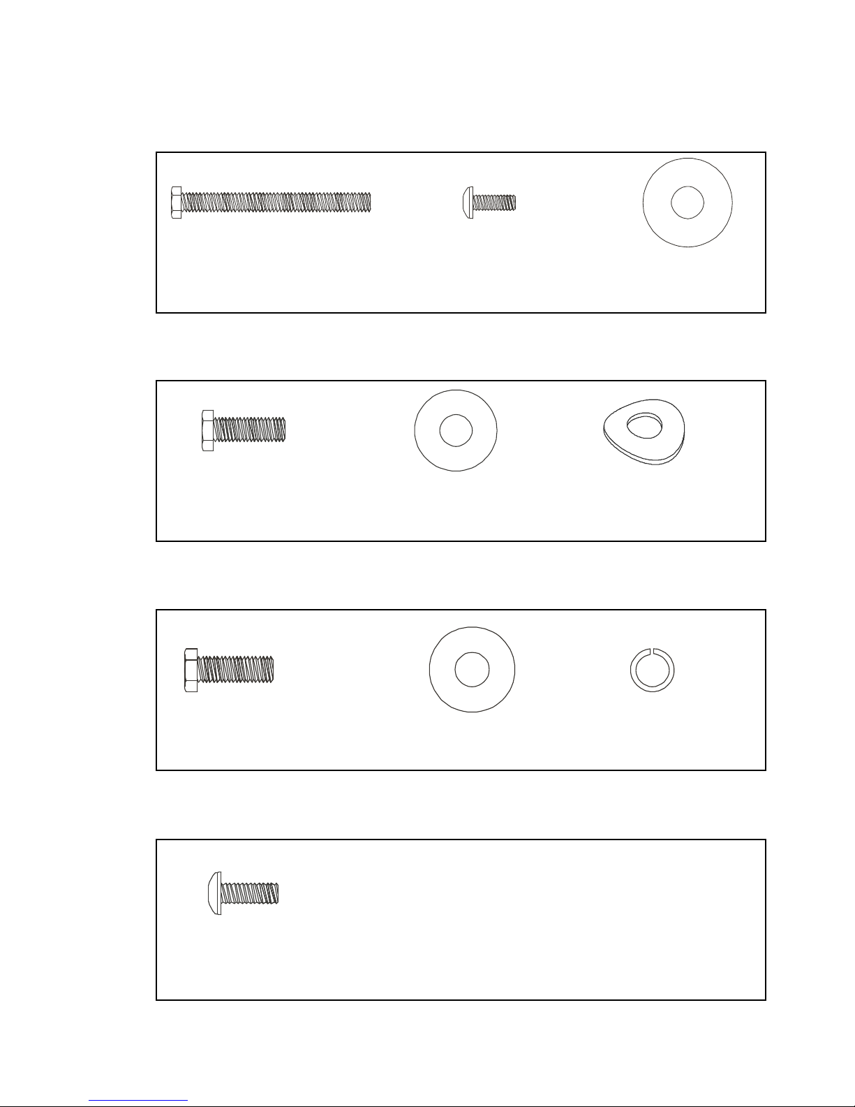
#50
. 3/8” x 2-1/4”
Hex Head Bolt (2 pcs)
#58
. M5 x 12mm
Phillips Head Screw
(2 pcs)
#71
. 3/8” x 25mm x 2T
Flat Washer (2 pcs)
#51
. 5/16” x 5/8”
Hex Head Bolt (7 pcs)
#72
. 5/16” x 18mm x 1.5T
Flat Washer (6 pcs)
#99
. 5/16” x 19mm x 1.5T
Curved Washer (1 pc)
#51
. 5/16” x 5/8”
Hex Head Bolt (2 pcs)
#72
. 5/16” x 18mm x 1.5T
Flat Washer (2 pcs)
#103
. 5/16” x 1.5T
Split Washer (2 pcs)
#58
. M5 x 12mm
Phillips Head Screw (6 pcs)
6
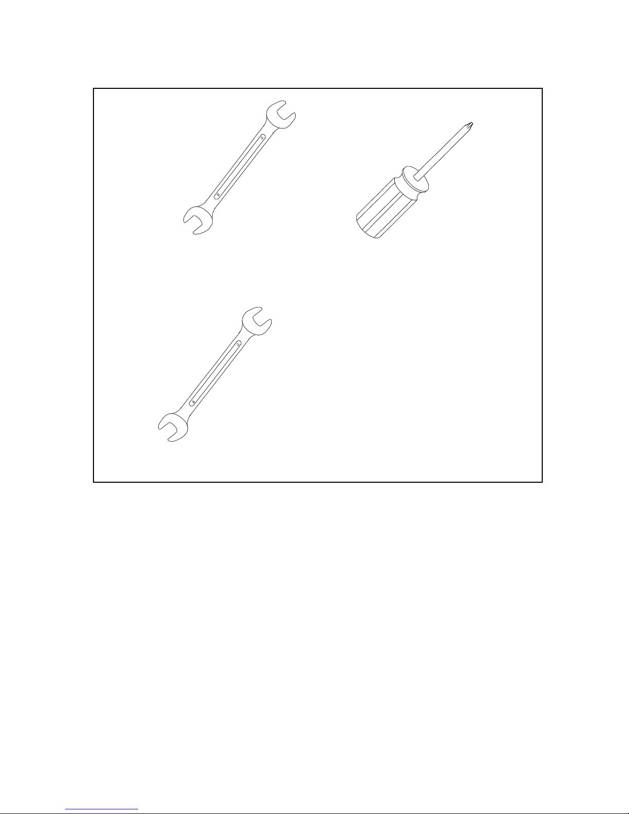
ASSEMBLY TOOLS
ASSEMBLY INSTRUCTIONS FOR UPRIGHT
PRE-ASSEMBLY
1. Using a razor knife (Box Cutter) cut the outside, bottom, edge of box along
the dotted Line. Lift Box over the unit and unpack.
2. Carefully remove all parts from carton and inspect for any damage or
missing parts. If damaged parts are found, or parts are missing, contact
your dealer immediately.
3. Locate the hardware package. Remove the tools first. Remove the
hardware for each step as needed to avoid confusion. The numbers in the
instructions that are in parenthesis (#) are the item number from the
assembly drawing for reference.
#92. 13/15mm Wrench #93. Phillips Head Screwdriver
#100. 12/14mm Wrench
7
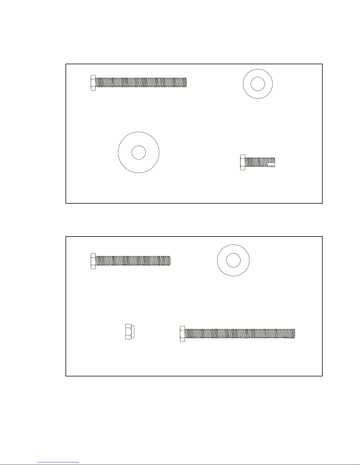
#50. 3/8” x 2-1/4”
Hex Head Bolt (2 pcs)
#58. M5 x 12mm Phillips
Head Screw (2 pcs)
#71. 3/8” x 25mm x 2T
Flat Washer (2 pcs)
#51. 5/16” x 5/8”
Hex Head Bolt (7 pcs)
#72. 5/16” x 18mm x 1.5T
Flat Washer (6 pcs)
#99. 5/16” x 19mm x 1.5T
Curved Washer (1 pc)
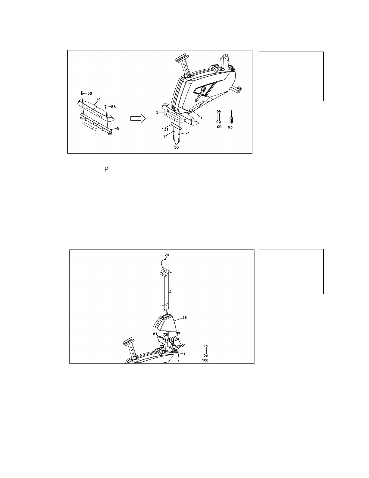
1
REAR STABILIZER
HARDWARE STEP 1
1. Attach the Rear Stabilizer Cover (41) to the Rear Stabilizer (5)
with two Phillips Head Screws (58). Tighten with the Phillips
Head Screw Driver (93).
2. Attach the Rear Stabilizer (5) to the Main Frame (1) by sliding
two Flat Washers (71) onto two Hex Head Bolts (50); insert
the bolts through the Rear Stabilizer Attachment Plate (131),
then into the rear stabilizer. Tighten using the 12/14 mm
Wrench (100).
2
CONSOLE MAST
HARDWARE STEP 2
1. Unravel the Computer Cable (29) and pull the twist tie wire
through the Console Mast Cover (38) (see illustration for the
correct orientation of the cover) and the Console Mast (2) until
the cable connector comes out the top opening of the Console
Mast.
2. Attach the Console Mast (2) onto the Main Frame (1) with
the seven Hex Head bolts (51). Place six Flat Washers (72)
on the side bolts and one Curved Washer (99) on the front
bolt. Tighten using the 12/14mm Wrench (100).
8
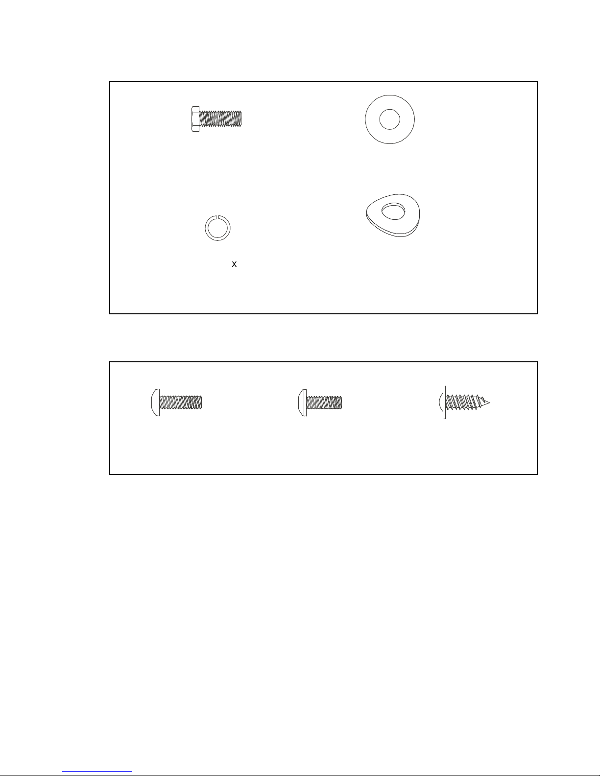
#51. 5/16” x 5/8”
Hex Head Bolt (2 pcs)
#72. 5/16” x 18mm x 1.5T
Flat Washer (2 pcs)
#103. 5/16” x 1.5T
Split Washer (2 pcs)
4
#58. M5 x 12mm Phillips
Head Screw (6 pcs)
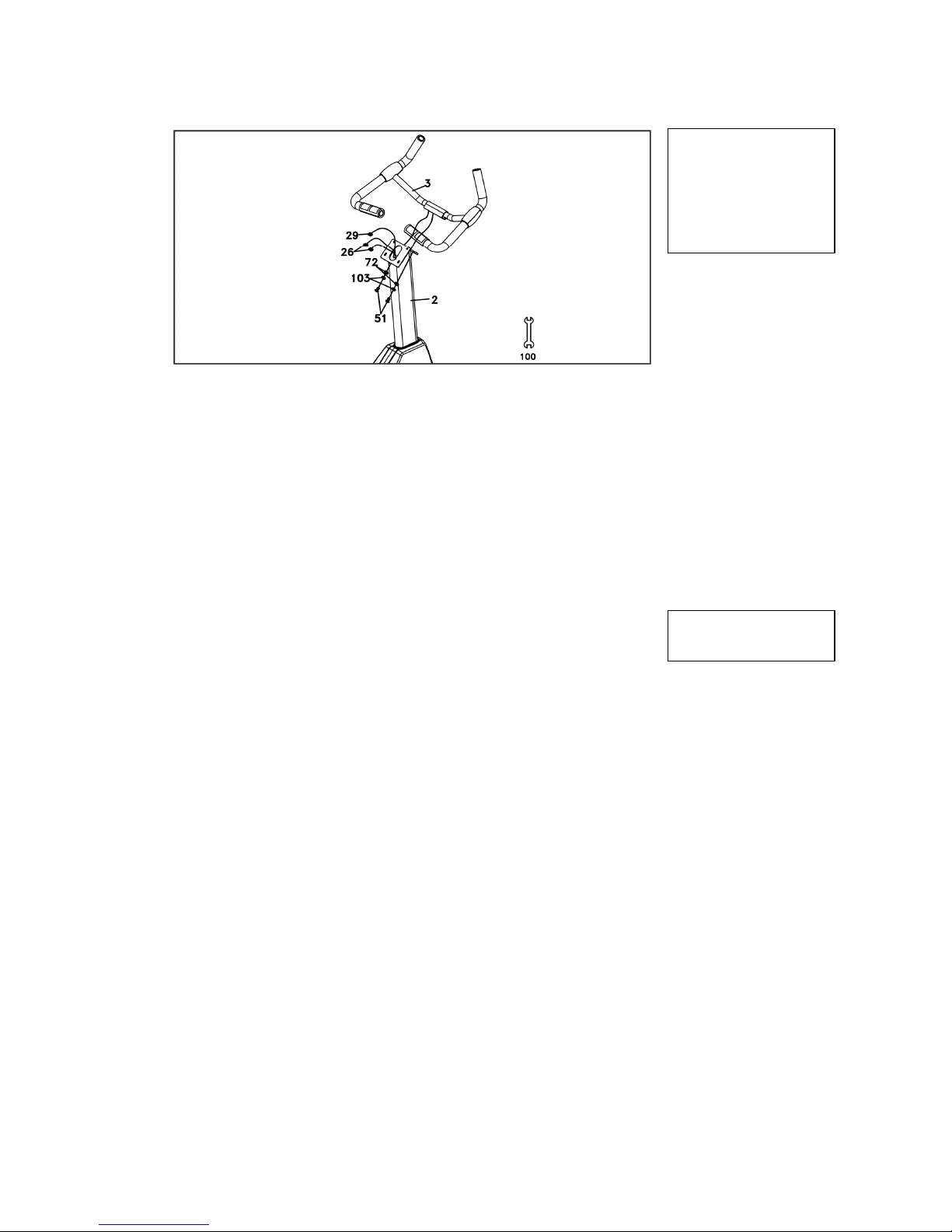
3
HANDLEBAR
HARDWARE STEP 3
1. Remove the plastic tie from the center of the handlebar (3).
Insert the two hand pulse cables (26) through the opening of
the handlebar mounting bracket on the front side of the
console mast tube (2). Pull the cables through the opening of
the console mounting bracket at the rear of the console mast
tube.
2. Attach the Handle Bar (3) to the Front Console Mast (2) with
the two Hex Head bolts (51), two Flat Washers (72) and two
Split Washers (103). Tighten using the 12/14mm Wrench
(100). Be careful not to pinch the cables when fastening.
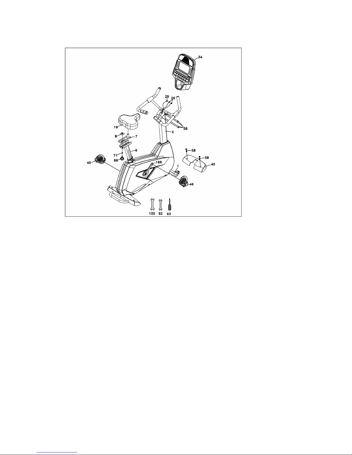
PLASTIC PARTS
HARDWARE STEP 4
1. Insert the Computer Cable (29) and two Hand pulse cables
(26) into the connectors in the back of the Console (34).
2. Attach the Console (34) onto the Console Mast (2) with four
Phillips Head Screws (58). Be careful not to pinch the cables
when fastening.
3. Attach the Front Stabilizer Cover (40) to the Main Frame (1)
with two Phillips Head Screws (58). Tighten with the Phillips
Head Screw Driver (93).
4. Install the Pedals (45 L, 46 R) onto the Cranks by using the
13/15mm Wrench (92). Remember that the left pedal has a
reverse thread and will be screwed into the crank in the
opposite rotation from normal threads. There is an L stamped
into the end of the threaded post of the left pedal and an R on
the end of the right post. Make sure to tighten the pedals as
much as you possibly can. It may be necessary to re-tighten the
pedals if you feel a thumping while pedaling the bike. A clicking
noise or thumping feeling is usually caused by loose pedals.
5. Install the Seat mount slide (7) onto the track on top of the seat
tube with the seat post facing forward. Place the nut plate (8)
onto the seat slide behind the seat post. Place the flat washer
(71) onto the fore/aft adjustment knob (86) and thread it into the
nut plate from underneath the seat tube track. Attach the seat
(19) to the seat post using the 12/14mm Wrench (100).
9
4
ASSEMBLY STEP 4
10
ASSEMBLY PACK CHECKLIST FOR RECUMBENT
1
HARDWARE STEP 1
2
HARDWARE STEP 2
#65
. 3/8” x 2-1/4”
Hex Head Bolt (4 pcs)
#77
. 3/8”
x 19mm x 1.5T
Flat Washer (6 pcs)
#84
. 3/8” x 25mm x 2T
Flat Washer (4 pcs)
#176
. 3/8” x 3/4”
Hex Head Bolt (6 pcs)
#71
. 3/8” x 1-3/4”
Hex Head Bolt (2 pcs)
#77
. 3/8”
x 19mm x 1.5T
Flat Washer (4 pcs)
#89. 3/8” x 7T
Nyloc Nut (4 pcs)
#175
. 3/8” x 2-3/4”
Hex Head Bolt (2 pcs)
11
3
HARDWARE STEP 3
4
HARDWARE STEP4
#68
. 5/16” x 5/8”
Hex Head Bolt (8 pcs)
#76
. 5/16” x 18mm x 1.5T
Flat Washer (6 pcs)
#82
. 5/16” x 1.5T
Split Washer (2 pcs)
#83
. 5/16” x 19mm x 1.5T
Curved Washer (2 pcs)
#98
. M6 x 15mm
Phillips Head Screw (4 pcs)
#99
. M5 x 12mm
Phillips Head Screw (8 pcs)
#105
. Ø4 x 16mm
Sheet Metal Screw (4 pcs)
 Loading...