

Sole Fitness FITNESS BIKE, Exercise Bike Owner's Manual
FITNESS BIKE O
WNER’S M
ANU
AL
PLEASE CAREFULLY READ THIS ENTIRE MANUAL BEFORE OPERATING YOUR NEW FITNESS BIKE

1
T
ABLE OF C
ONTEN
T
S
Important Safety Instructions
2
Important Operation Instructions
3
Transport Instructions
3
Assembly Instructions
4
Fitness Bike Features
10
Operation of Your New Fitness Bike
11
Programmable Features
14
Using Heart Rate Transmitter(Optional)
21
General Maintenance
23
Exploded View Diagram
24
Parts List
25
ATTENTION
THIS FITNESS BIKE IS INTENDED FOR
RESIDENTIAL USE ONLY
AND IS WARRANTED FOR
THE APPLICATION. ANY OTHER APPLICATION
VOIDS
THIS WARRANTY IN ITS ENTIRETY.
SR889-YB12_1111(SL)A

2
IMPOR
T
ANT SAFE
T
Y INSTR
UCTIONS
W
ARNING -
Read all instructions before using this appliance.
Do not operate fitness bike on deeply padded, plush or shag carpet. Damage to both carpet
and fitness bike may result.
Keep children away from the fitness bike. There are obvious pinch points and other caution
areas that can cause harm.
Keep hands away from all moving parts.
Do not operate where aerosol spray products are being used or where oxygen is being
administered. Sparks from the motor may ignite a highly gaseous environment.
Never drop or insert any object into any openings.
Do not use outdoors.
Do not attempt to use your fitness bike for any purpose other than for the purpose it is
intended.
The hand pulse sensors are not medical devices. Various factors, including the user’s
movement, may affect the accuracy of heart rate readings. The pulse sensors are intended
only as exercise aids in determining heart rate trends in general.
Wear proper shoes. High heels, dress shoes, sandals or bare feet are not suitable for use
on your fitness bike. Quality athletic shoes are recommended to avoid leg fatigue or injury.
SAVE
THESE INSTRUCTIONS - THINK SAFETY!

3
IMPOR
T
ANT OPER
A
TION INSTR
UCTIONS
NEVER
expose this fitness bike to rain or moisture. This product is NOT designed for use
outdoors, near a pool or spa, or in any other high humidity environment. The operating
temperature specification is 40 to 120 degrees Fahrenheit, and humidity is 95%
non-condensing (no water drops forming on surfaces).
NEVER
operate this fitness bike without reading and completely understanding the results
of any operational change you request from the computer.
Understand that changes in resistance do not occur immediately. Set your desired
resistance on the computer console and release the adjustment key. The computer will obey
the command gradually.
Use caution while participating in other activities while pedaling on your fitness bike; such as
watching television, reading, etc. These distractions may result in serious injury.
Do not use excessive pressure on console control keys. They are precision set to function
properly with little finger pressure. If you feel the buttons are not functioning properly with
normal pressure contact your dealer.
TR
ANSPOR
T
INSTR
UCTIONS
The fitness bike is equippped with two transport wheels which are engaged when the rear of the
fitness bike is lifted.
4
ASSEMBL
Y P
A
CK CHECKLIST
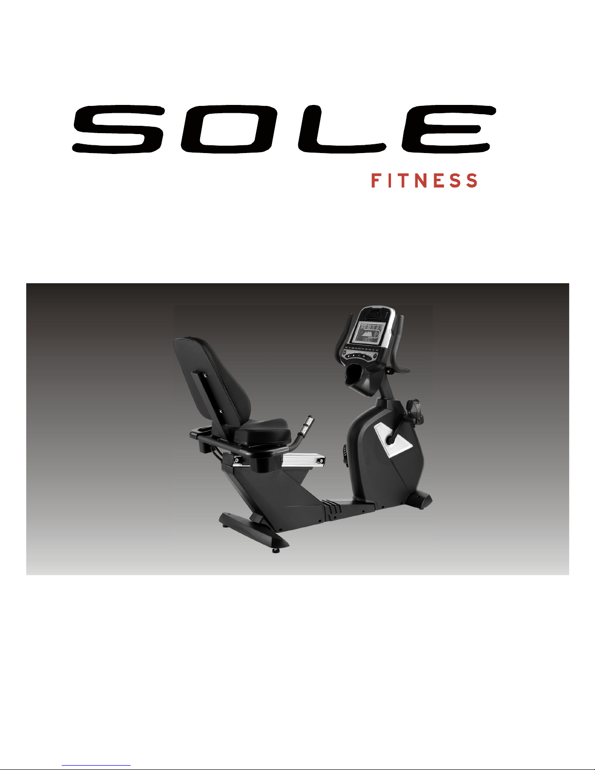
1
HARDW
ARE STEP 1
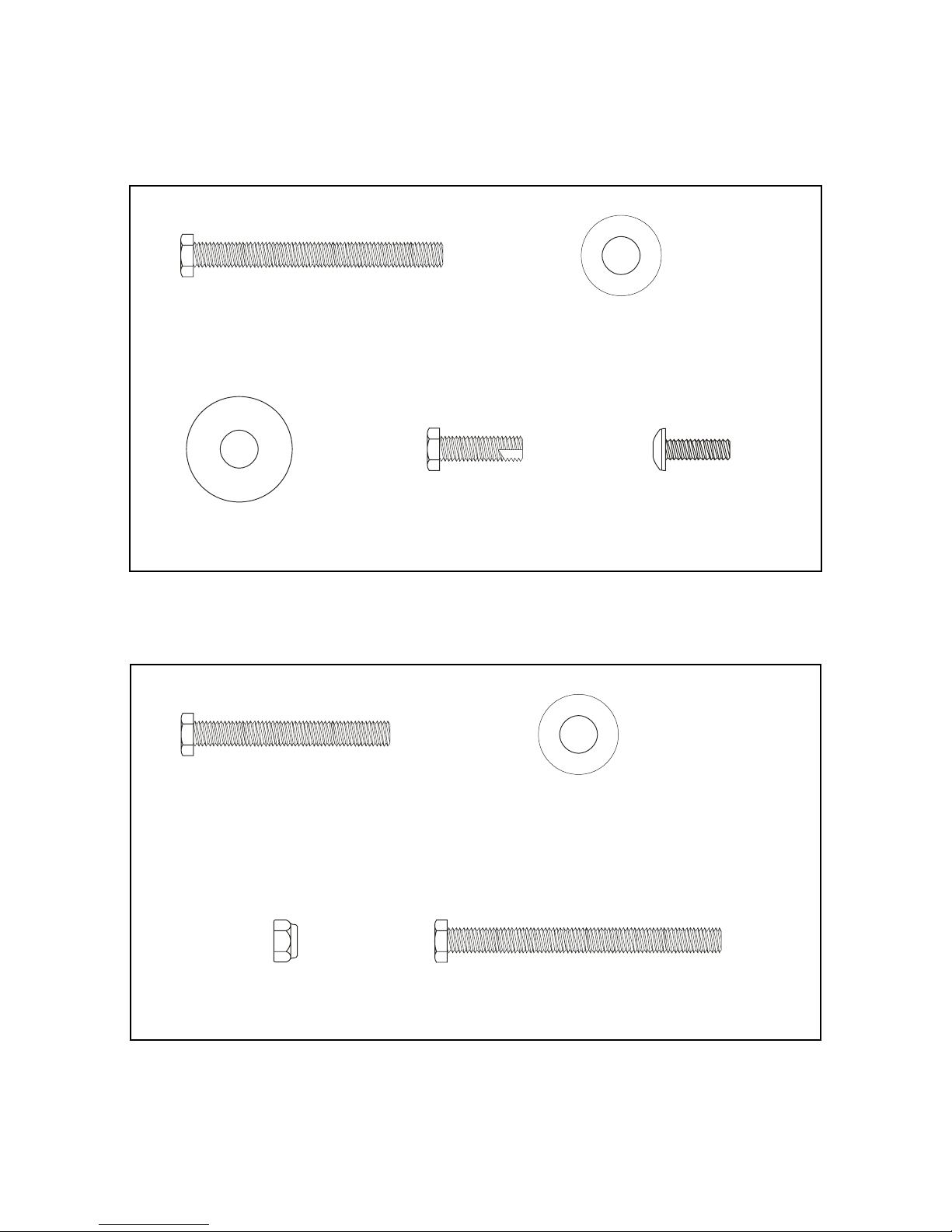
2
HARDW
ARE STEP 2
#65
. 3/8
”
x 2-1/4”
Hex Head Bolt (4 pcs)
#77
. 3/8
”
x 19 x 1.5T
Flat Washer (6 pcs)
#84
. 3/8
”
x 25 x
2T
Flat Washer (4 pcs)
#176
. 3/8
”
x 3/4”
Hex Head Bolt (6 pcs)
#136
. M5 x 15mm
Phillips Head Screw (4 pcs)
#71
. 3/8
”
x 1-3/4”
Hex Head Bolt (2 pcs)
#77
. 3/8
”
x 19 x 1.5T
Flat Washer (4 pcs)
#89
. 3/8
”
x 7T
Nyloc Nut (4 pcs)
#175
. 3/8
”
x 2-3/4”
Hex Head Bolt (2 pcs)
5
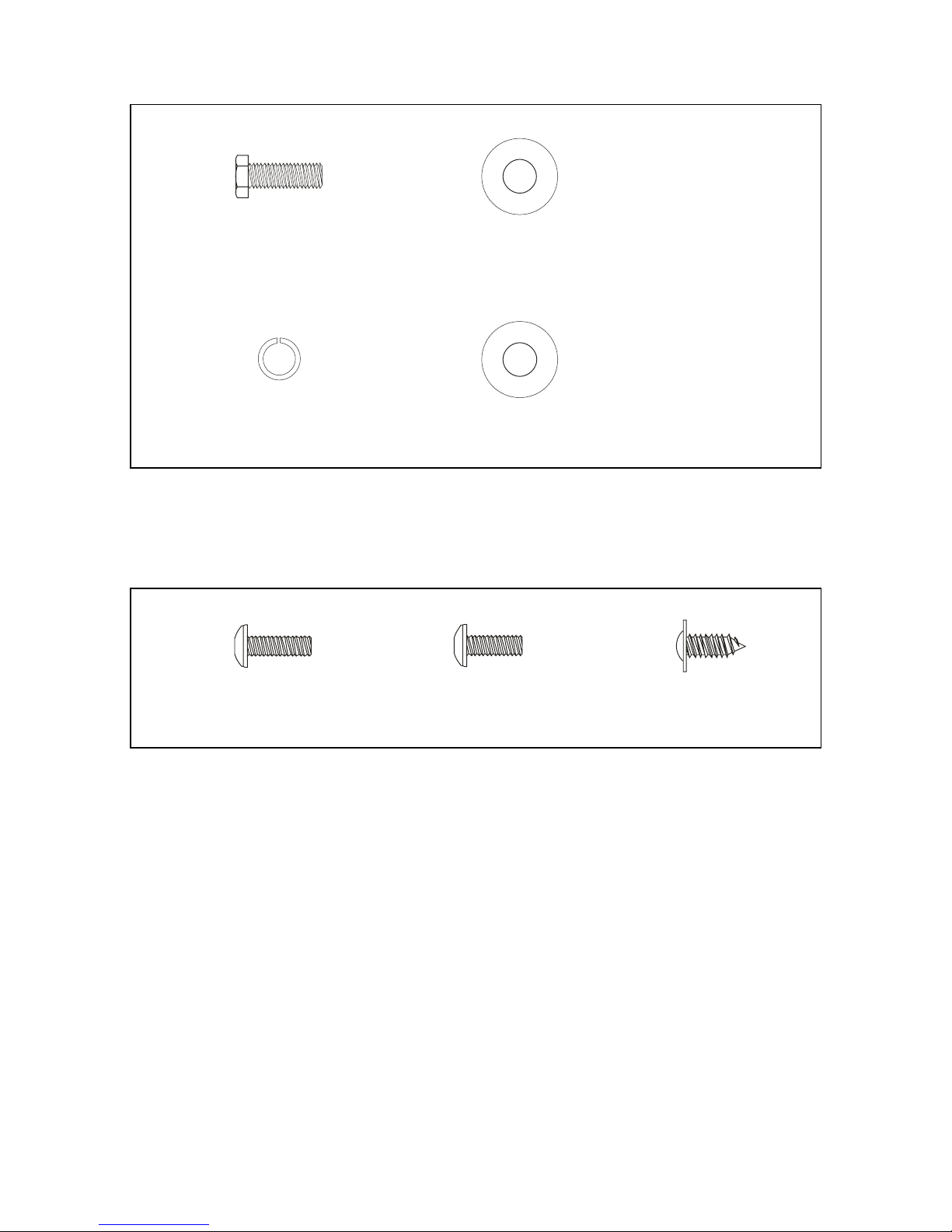
3
HARDW
ARE STEP 3
4
HARDW
ARE STEP 4
#68
. 5/16
”
x 5/8”
Hex Head Bolt (8 pcs)
#76
. 5/16
”
x 18 x 1.5T
Flat Washer (6 pcs)
#82
. 5/16
”
x 1.5T
Split Washer (2 pcs)
#83
. 5/16
”
x 19 x 1.5T
Curved Washer (2 pcs)
#98
. M6 x 15mm
Phillips Head Screw (4 pcs)
#99
. M5 x 12mm
Phillips Head Screw (8 pcs)
#105
. 4 x 16mm
Sheet Metal Screw (4 pcs)
6
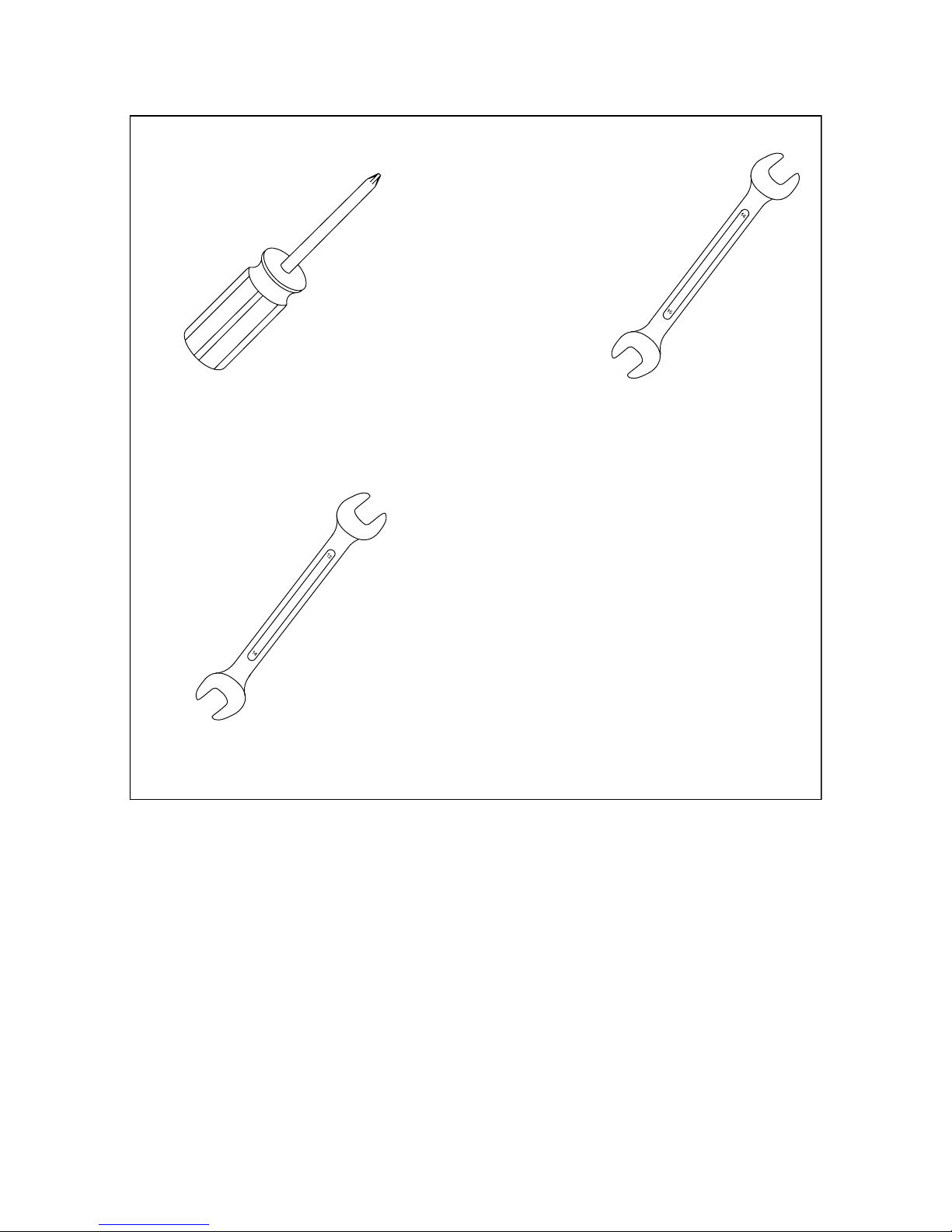
ASSEMBLY TOOLS
ASSEMBL
Y INSTRUC
TIONS
PRE-ASSEMBLY
1. Using a razor knife (Box Cutter) cut the outside, bottom, edge of box along the dotted Line. Lift Box over the
unit and unpack.
2. Carefully remove all parts from carton and inspect for any damage or missing parts. If damaged parts are
found, or parts are missing, contact your dealer immediately.
3.
Locate the hardware package. Remove the tools first. Remove the hardware for each step as needed to
avoid confusion. The numbers in the instructions that are in parenthesis (
#
) are the item number from the
assembly drawing for reference.
#114
. Phillips Head Screwdriver
#132
. 14/15mm Wrench
#112
. 12/14mm Wrench
7
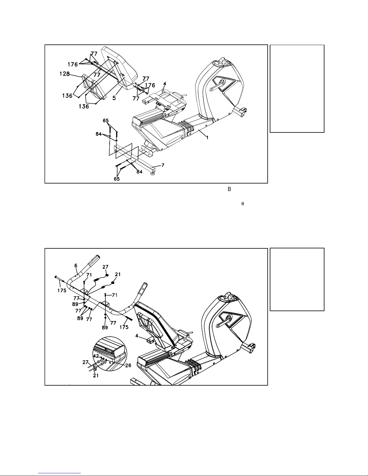
1. Install the Seat Handle Bar (6) onto the Seat Carriage (4) with four Hex Head Bolts (2 - 71
& 2 -
175
), four Flat Washers (77) and four Nyloc Nuts (89) using the 12/14mm Wrench
(
112
) and 14/15mm Wrench (
132
).
2. Plug the two Hand pulse Cables (21 & 27) into the two rear receiver ports (26) located on
the left side rear cover, just under the seat.
3. Be sure the connectors are plugged into the correct ports. Each connector has a tag that
indicates either L for Left, which plugs into port (
42
) in the drawing, and R for right, plugs
into port (26).
#65
. 3/8” x 2-1/4”
Hex Head Bolt (4 pcs)
#77
. 3/8” x 19 x 1.5T
Flat Washer (6 pcs)
#84
. 3/8” x 25 x 2T
Flat Washer (4 pcs)
#176
. 3/8” x 3/4”
Hex Head Bolt (6 pcs)
#136
. M5 x 15mm
Phillips Head Screw
(4 pcs)
#71
. 3/8” x 1-3/4”
Hex Head Bolt (2 pcs)
#77
. 3/8” x 19 x 1.5T
Flat Washer (4 pcs)
#89
. 3/8” x 7T
Nyloc Nut (4 pcs)
#175
. 3/8” x 2-3/4”
Hex Head Bolt (2 pcs)
1
REAR
STABILIZER
& SEAT
BACK
HARDWARE
STEP 1
2
SEAT
HANDLE BAR
HARDWARE
STEP
2
1. Install the Rear Stabilizer (7) onto the Main Frame (1) with four Hex Head Bolts (65) and
four Flat Washers (84) using the 12/14mm Wrench (
112
).
2. Install the Seat Back Cover (
128
) onto Seat Back Bracket (5) with four Phillips Head
Screws (
136
) using the Phillips Head Screw Driver(
114
).
3. Install Seat Back Bracket (5) onto the Seat Carriage (4) with six Hex Head Bolts (
176
) and
six Flat Washers (77) using the 12/14mm Wrench (
112
).
8
#68
. 5/16” x 5/8”
Hex Head Bolt (8 pcs)
#76
. 5/16” x 18 x 1.5T
Flat Washer (6 pcs)
#82
. 5/16” x 1.5T
Split Washer (2 pcs)
#83
. 5/16” x 19 x 1.5T
Curved Washer (2 pcs)
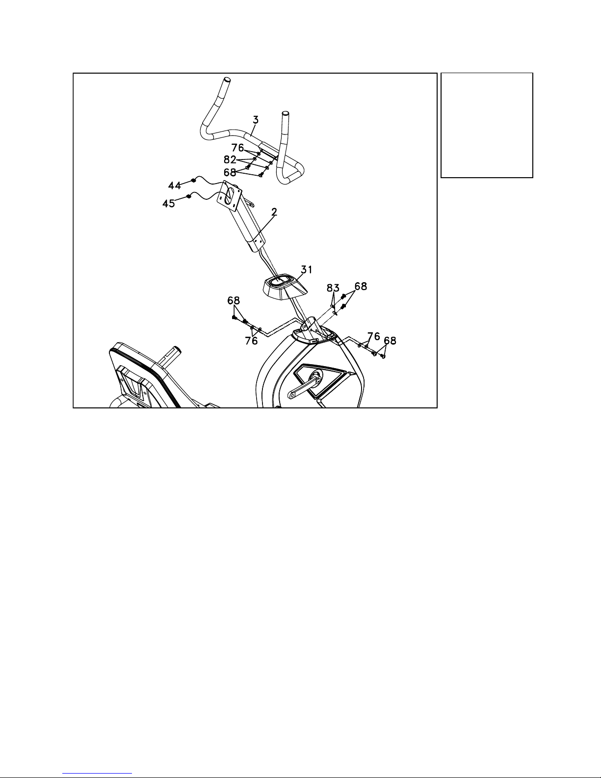
1. Slide the Console Mast Cover (31) onto the Console Mast (2). Make sure the plastic cover
is in the correct orientation.
2. Feed the twist tie that is connected to the Computer Cable (44) and Hand pulse Cable (45)
through the bottom of the Console Mast (2) and out through the opening at the top.
3. Insert the Console Mast (2) into the receiving tube (make sure it is oriented like the
illustration; be careful not to pinch the cables between the tubes, as damage to the
electronics could occur) of the Main Frame (1) with six Hex Head Bolts (68), four Flat
Washers (76) on the sides of the tube and two Curved Washers (83) on the front of the
tube. Tighten using the 12/14mm Wrench (
112
).
4. Remove the white Styrofoam pad (factory installed to prevent bolts from being accidentally
dropped into the Bike).
5. Remove the plastic tie that holds the plastic cover on the center of the handlebar (3).
Attach the Console Mast Handle bar Assembly (3) onto the Console Mast (2) with two Hex
Head Bolts (68), two Flat Washers (76) and two Split Washers (82) using the 12/14mm
Wrench (
112
).
3
CONSOLE MAST
HARDWARE
STEP
3
 Loading...