

Sole Fitness E98 Owner's Manual

PLEASE CAREFULLY READ THIS ENTIRE MANUAL BEFORE
OWNER’S MANUAL

2
T
ABLE OF C
ONTENTS
I
mportant Safety Instructions
3
I
mportant Electrical Informa
tion
4
I
mportant Opera
tion I
nstructions
5
Transport I
nstructions
5
A
ssembly I
nstructions
8
Elliptical Features
13
Opera
tion of Y
our New Elliptical
14
Programmable Features
17
U
sing Heart Rate Monitor
23
G
eneral Main
tenance
25
Exploded View Diagram
26
Parts List
27
ATTENTION
THIS ELLIPTICAL IS INTENDED FOR RESIDENTIAL USE ONLY AND IS W
ARRANTED FOR THE
APPLICA
TION. ANY O
THER APPLICA
TION V
OIDS THIS W
ARRANT
Y IN ITS ENTIRETY.
XE869A-YE21_1111(N)A
3
IMPORTANT SAFETY INSTR
UCTIONS
W
ARNING
- R
ead all instruc
tions before using this appliance.
D
ANGER - To r
educ
e the r
isk of elec
tric shock disc
onnec
t y
our SOLE elliptical fr
om the elec
trical
outlet
pr
ior t
o cleaning and/or ser
vice work.
W
ARNING - To r
educ
e the risk of burns, fire, elec
tric shock, or injur
y t
o persons
, install
the elliptical on a flat lev
el sur
fac
e with access to a 110-volt
, 15-amp grounded outlet with only
the
elliptical plugged into the cir
cuit.
DO NO
T USE AN EX
TENSION CORD UNLESS IT IS A 14AWG OR BETTER, WITH ONLY ONE
OUTLET ON THE END: DO NO
T ATTEMPT T
O DISABLE THE GR
OUNDED PL
UG B
Y USING
IMPR
OPER AD
APTERS, OR IN ANY WAY MODIFY THE C
ORD SET.
A ser
ious shock or fir
e hazar
d ma
y r
esult along with c
omput
er malfunctions
. S
ee Gr
ounding I
nstructions
, page 3.
Do not operat
e elliptical on deeply padded
, plush or shag car
pet
. Damage to both car
pet
and
elliptical ma
y r
esult.
Keep children awa
y fr
om the elliptical. Ther
e ar
e obvious pinch points and other caution areas tha
t
can cause harm.
Keep hands awa
y fr
om all mo
ving parts.
Nev
er operat
e the elliptical if it has a damaged cor
d or plug
. I
f the elliptical is not work
ing properly,
call y
our dealer.
Keep the c
ord awa
y fr
om heated surfaces.
Do not operat
e wher
e aerosol spray pr
oduc
ts ar
e being used or wher
e oxy
gen is being
administered
. Spar
ks fr
om the mot
or ma
y ig
nit
e a highly gaseous en
vir
onment.
Nev
er dr
op or inser
t an
y object into any openings.
Do not use outdoors.
T
o disc
onnect
, tur
n all controls t
o the off position, then r
emove the plug fr
om the outlet.
Do not a
ttempt t
o use your elliptical f
or any pur
pose other than f
or the pur
pose it is
intended.
The hand pulse sensors ar
e not medical devices. V
arious factors
, including the user’s mov
ement
,
ma
y aff
ect the ac
curac
y of hear
t rat
e r
eadings. The pulse sensors are in
tended
only as exer
cise
aids in determining hear
t rat
e tr
ends in general.
Wear pr
oper shoes
. H
igh heels
, dr
ess shoes, sandals or bar
e f
eet ar
e not suitable for use on your
elliptical
. Q
ualit
y a
thletic shoes ar
e recommended t
o avoid leg fa
tigue.
SAVE
THESE INSTRUCTIONS - THINK SAFETY!
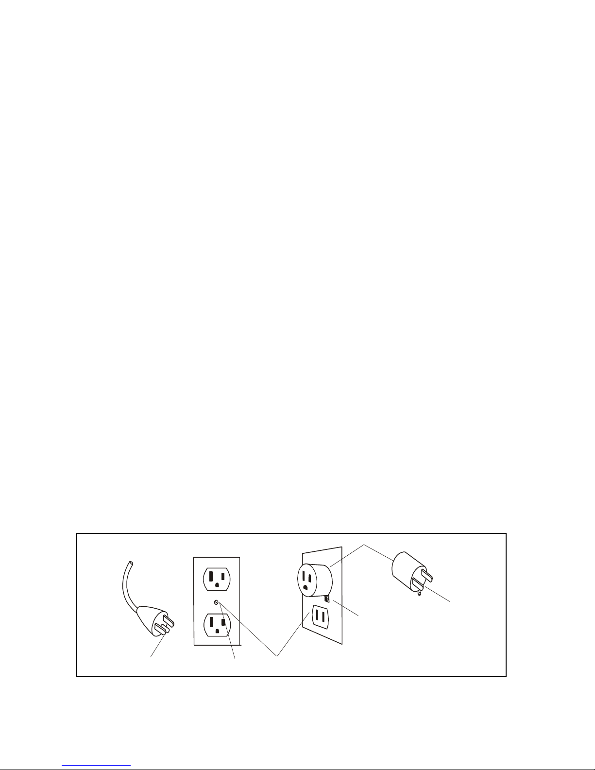
Grounded Outlet
Grounding Pin
Grounded Outlet Box
Adapter
Metal Screw
Tab of
Grounding Screw

4
IMPORTANT ELEC
TRICAL INSTR
UCTIONS
W
ARNING!
NE
VER remove an
y cover without first disc
onnec
ting A
C power.
I
f v
oltage v
aries b
y t
en percen
t (10%) or more, the perfor
manc
e of y
our elliptical ma
y be affec
ted.
Such
c
onditions ar
e not covered under your warranty. I
f y
ou suspec
t the v
oltage is low
, contac
t y
our
local power c
ompan
y or a lic
ensed elec
trician for pr
oper t
esting.
NE
VER expose this elliptical t
o r
ain or moisture. This pr
oduc
t is NOT desig
ned f
or use out
doors, near a
pool or spa, or in an
y other high humidit
y en
vir
onment. T
he oper
ating tempera
ture specification is 40 t
o
120 deg
r
ees F
ahr
enheit, and humidit
y is 95% non-condensing
(no wat
er dr
ops for
ming on sur
fac
es).
GR
OUNDING INSTRUC
TIONS
T
his produc
t must b
e gr
ounded. If the elliptical should malfunc
tion or br
eakdo
wn, ground- ing
provides a pa
th of least r
esistanc
e f
or electr
ic current
, r
educing the r
isk of elec
tric shock. T
his pr
oduc
t is
equipped with a cor
d having an equipment-gr
ounding plug. The plug must be
plugged int
o an
appr
opriat
e outlet tha
t is pr
oper
ly installed and grounded in accor
danc
e with
all local c
odes and
or
dinances.
D
ANGER - Improper connection of the equipment-grounding conductor can result in a
risk of electric shock. Check with a qualified electrician or serviceman if you are in doubt
as to whether the product is properly grounded. Do not modify the plug provided with
the product if it will not fit the outlet; have a proper outlet installed by a qualified
electrician. T
his pr
oduc
t is f
or use on a nominal 230-volt cir
cuit
, and has a grounding plug tha
t looks like
the plug illustrat
ed below. A t
emporary adapt
er that looks like the adapt
er illustrat
ed below ma
y be used
to c
onnec
t this plug t
o a 2-pole receptacle as sho
wn belo
w if a pr
oper
ly grounded
outlet is not available.
T
he t
emporary adapt
er should be used only un
til a pr
oper
ly grounded
outlet
, (sho
wn belo
w) can be
installed b
y a qualified electr
ician. T
he green c
olor
ed rigid ear
-lug, or the like
, extending fr
om the adapter,
must be c
onnect
ed t
o a per
manen
t ground such as a proper
ly grounded outlet bo
x cover. Whenev
er
the adapt
er is used
, it must be held in place b
y a
metal screw.

5
IMPORTANT OPER
A
TION INSTR
UCTIONS
NEVER
operat
e this elliptical without r
eading and c
omplet
ely understanding the r
esults of any
operational change y
ou request fr
om the c
omputer.
Understand tha
t changes in resistanc
e and incline do not oc
cur immediately
. S
et y
our de- sir
ed
r
esistance on the c
omput
er c
onsole and r
elease the adjustmen
t key. The c
omput
er will
obey the
c
ommand gradually.
NEVER
use y
our elliptical during an electrical storm. Sur
ges ma
y occur in your facilit
y or
household pow
er supply tha
t c
ould damage elliptical c
omponents. Unplug the elliptical
dur
ing
an electrical storm as a pr
ecaution.
U
se caution while par
ticipa
ting in other activities while pedaling on y
our elliptical; such as
wat
ching t
elevision, r
eading
, etc. T
hese distractions ma
y r
esult in ser
ious injury.
Alway
s hold on t
o a handr
ail or hand bar while making contr
ol changes (incline
, r
esistance, etc.).
Do not use exc
essiv
e pressure on c
onsole control keys. T
hey are precision set t
o func
tion proper
ly
with little finger pressure. P
ushing har
der is not going to make the unit go fast
er
or slower
. I
f y
ou
f
eel the butt
ons ar
e not func
tioning proper
ly with nor
mal pr
essur
e contact y
our dealer.
PO
WER C
ONNECTOR - FR
ONT
, LEFT SIDE OF UNIT
TR
ANSPORT INSTR
UCTIONS
T
he elliptical is equippped with two tr
anspor
t wheels which ar
e engaged when
the rear
of the elliptical is lif
ted.
ASSEMBL
Y P
A
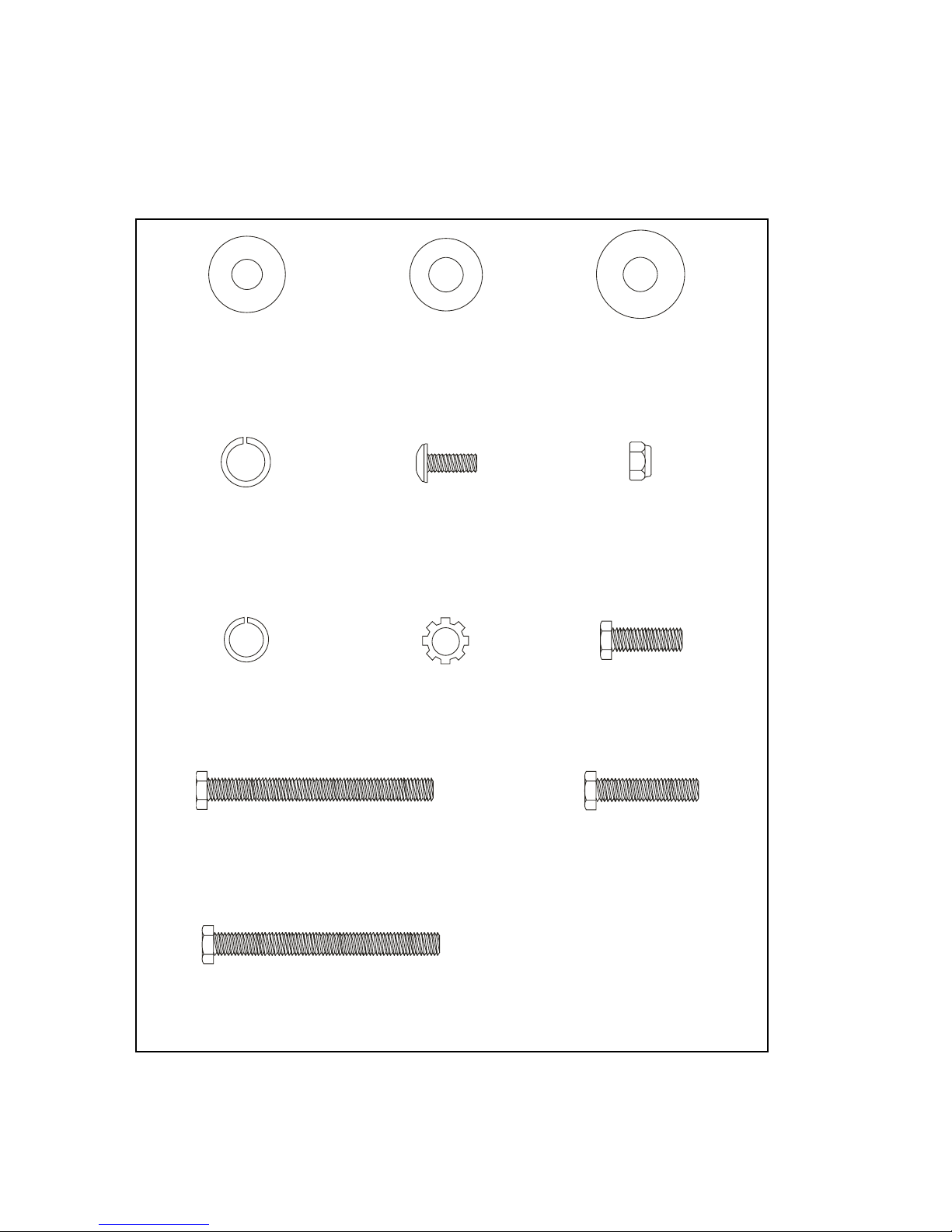
CK CHECKLIST
1
HARDW
ARE STEP 1
#158. 3/8”
x 19 x 1.5T
Flat W
asher (2 pcs)
#154
. 5/16”
x 20 x 1.5T
Flat W
asher (4 pcs)
#164
. 3/8”
x 23 x 2T
Curved Washer (2 pcs)
#167
. 3/8”
x 2T
Split W
asher (1 pc)
#128.
M5 x 10mm
P
hillips Head Screw (4 pcs)
#145
. 3/8”
x 7T
Nyloc Nut (2 pcs)
#166
. 5/16”
x 1.5T
Split W
asher (4 pcs)
#168
. 5/16”
S
tar W
asher (4 pcs)
#116
. 3/8” x 3/4”
He
x Head B
olt (2 pcs)
#115
. 5/16”
x 2-1/4”
He
x Head B
olt (4 pcs)
#117
. 3/8”
x 1-1/2”
He
x Head B
olt (2 pcs)
#118
. 3/8”
x 2-1/4”
He
x Head B
olt (1 pc)
7
2
HARDW
ARE STEP 2
3
HARDW
ARE STEP 3
4
HARDW
ARE STEP 4
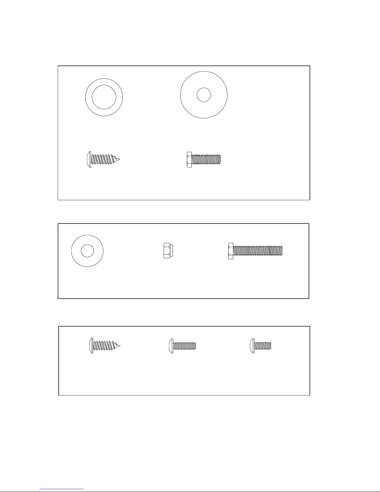
#163
. 25mm
Wave W
asher (4 pcs)
#160
. 3/8”
x 30 x 2T
F
lat Washer (2 pcs)
#132
. 3.5 x 12mm
Sheet M
etal Screw (8 pcs)
#116.
3/8”
x 3/4”
He
x Head B
olt (2 pcs)
#154
. 5/16”
x 20 x 1.5T
Flat W
asher (2 pcs)
#143
. 5/16”
x 7T
Nyloc Nut (2 pcs)
#114
. 5/16”
x 1-1/4”
He
x Head B
olt (2 pcs)
#132
. 3.5 x 12mm
Sheet M
etal Screw (10 pcs)
#129
. M5 x 15mm
P
hillips Head Screw (29 pcs)
#131
. M6 x 10mm
P
hillips Head Screw (4 pcs)

8
ASSEMBLY TOOLS
#171
. P
hillips Head Screwdriver
#170
. Shor
t P
hillips Head Screwdriver
#172
. 12/14mm Wrench
#169
. 13/14mm Wrench
ASSEMBL
Y INSTRUC
TIONS
PRE-ASSEMBLY
1. Using a razor k
nif
e (Box C
utt
er) cut the outside
, bottom, edge of box along
the
dott
ed Line
. Lif
t Box over the unit and unpack.
2. Carefully r
emove all par
ts fr
om carton and inspec
t f
or an
y damage or missing parts. I
f
damaged par
ts ar
e f
ound
, or parts ar
e missing
, contac
t y
our dealer
immediat
ely.
3. L
ocate the hardwar
e pack
age
. R
emo
ve the t
ools first
. R
emo
ve the hardware f
or each
st
ep as needed to avoid c
onfusion. T
he numbers in the instructions
tha
t ar
e in
parenthesis (#) ar
e the it
em number fr
om the assembly drawing for refer
ence.

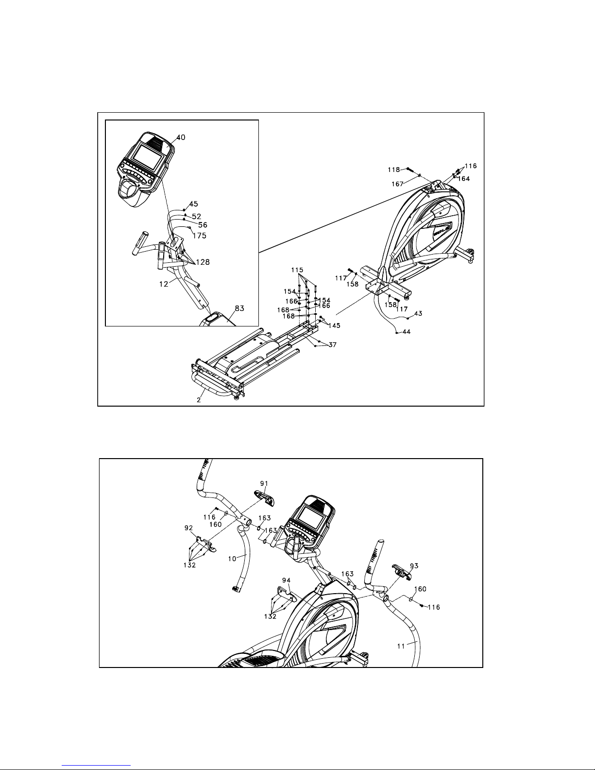
9
1
INCLINE R
AIL
& C
ONSOLE M
AST
HARDW
ARE STEP 1
1.
I
nstall the Incline R
ail A
ssembly (2) into the U-
channel br
acket of the M
ain Fr
ame (1). S
ecur
e
with the six bolts & associated hardwar
e as f
ollows: From the sides install two He
x Head Bolts
(
117
) with two Flat W
ashers (
158
) and two N
ylon Nuts (
145
). From the t
op install four He
x
Head Bolts (
115
), f
our Split W
ashers (
166
), f
our Flat W
ashers (
154
), and four S
tar W
ashers
(
168
), and tight
en with the Wrenches provided (
169 &
172).
2.
C
onnec
t the thr
ee I
ncline Motor Pow
er lines b
y matching the Red, W
hit
e and Black c
olor
c
odes of the wir
es (43) and the 3-pin position Sensor C
onnector (44). L
ocate the C
onsole
M
ast (12) and C
onsole M
ast Cov
er (83) and slide the Cover onto the M
ast as far as it will go.
M
ake sure the C
onsole M
ast Cov
er is facing the corr
ect way
. A
t the t
op opening of the M
ain
Frame of the elliptical is a C
omput
er C
able (45); S
ecur
e the fr
ee end of the twist tie that
e
xits thebott
om of the console mast (12) t
o this cable
. P
ull the opposite end of this t
wist tie
up thr
ough the c
onsole mast (12) until the cable e
xits the top. I
nstall the C
onsole M
ast (12)
into the receiving bracket on the top of the M
ain Fr
ame (1). P
ull slightly on the c
omput
er
cable a
t the t
op of the mast while installing. This will ensur
e the cable does not get pinched
and shorted dur
ing c
onsole mast assembly.
3.
P
ut one Split W
asher (
167
) onto the L
ong He
x Head B
olt (
118
) and install through the lef
t
side of the r
eceiving bracket into the C
onsole M
ast (12). Put
the two Curved Washers (
164
)
onto the two Shor
t He
x Head Bolts (
116
) and install thr
ough the front of the c
onsole mast
.
U
sing Wrench (
172
), tigh
ten the (
116
) bolts first
, then the (
118
) bolt
, and lastly the f
our
th
bolt
, which is pre-installed
, fir
mly. These bolts should be tightened as much as y
ou possibly
can. T
his is the main joint of the unit
. I
f not tightened sufficien
tly
, this c
ould
lead t
o noise
and instabilit
y issues
.
4.
P
lug the C
omput
er C
able (45), two Hand pulse C
ables (52 & 56
), and green Ground C
able
(
175
) into the back of the c
onsole . S
ecur
e the C
onsole (40) on the c
onsole moun
ting
plate with four Phillips Head Screw
s (
128).
2
HANDLEBAR
HARDW
ARE STEP 2
1. Install two Washers (163) onto the Left and Right sides of the Handle Bar axle.
2. Slide the Left (10) and Right (11) Handle Bars onto the appropriate side of the axle. The
handlebars have a small sticker on them indicating L (left) and R(right). Make sure the
handlebars are facing the correct direction – see illustration.
3. Install two Flat Washers (160) onto the two Hex Head Bolts (116). Insert and and tighten in
the threaded holes at the ends of each axle.
4. Install the Handle Bar Covers (91 to 92) and (93 to 94) over the Console Mast axle
connections and secure with the eight Sheet Metal Screws (132).
#158. 3/8’’ x 19 x 1.5T
Flat Washer (2 pcs)
#154. 5/16’’ x 20 x 1.5T
Flat Washer (4 pcs)
#164. 3/8’’ x 23 x 2T
Curved Washer (2 pcs)
#167. 3/8’’ x 2T
Split Washer (1 pc)
#128. M5 x 10mm
Phillips Screw (4 pcs)
#145. 3/8’’ x 7T
Nylon Nut (2 pcs)
#166. 5/16’’ x 1.5T
Split Washer (4 pcs)
#168. 5/16’’
Star Washer (4 pcs)
#116. 3/8’’ x 3/4’’
Hex Head Bolt (2 pcs)
#115. 5/16’’ x 2-1/4’’
Hex Head Bolt (4 pcs)
#117. 3/8’’ x 1-1/2’’
Hex Head Bolt (2 pcs)
#118. 3/8’’ x 2-1/4’’
Hex Head Bolt (1 pc)
#163. 25mm
Wave Washer (4 pcs)
#160. 3/8’’ x 30 x 2T
Flat Washer (2 pcs)
#132. 3.5 x 12mm Sheet
Metal Screw (8 pcs)
#116. 3/8’’ x 3/4’’
Hex Head Bolt (2 pcs)
10
1
ASSEMBLY
STEP 1
2
ASSEMBLY
STEP 2
 Loading...