

SkyWay Series Multi-Point Operator’s Guide
SkyWay Series
Multi-Point
Operator’s Guide
for SkyWay-Net and SkyMate
Wireless Bridge/Routers
i

About This Manual
About This Manual
The information contained in this document is subject to change without notice.
Solectek Corporation shall not be liable for errors contained herein or for
incidental or consequential damage in connection with the furnishing,
performance, or use of this material. Reproduction, adaptation, or translation
without prior written permission is prohibited, except as allowed under the
copyright laws.
Solectek Corporation makes no warranty of any kind with regard to this material,
including, but not limited to, the implied warranties or merchantability and fitness
for a particular purpose.
Document Version: 1.00
Part Number: 1288601
For use with SkyWay-Net and SkyMate software versions 3.0 and higher.
Trademarks & Copyrights
SkyWay is a registered trademark of Solectek Corporation
Solectek is a trademark of Solectek Corporation.
IBM and AT are registered trademarks of International Business Machines
Corporation.
Microsoft and MS-DOS are registered trademarks of Microsoft Corporation.
Novell and NetWare are registered trademarks of Novell, Inc.
Other trademarks are the property of their respective holders.
Copyright Solectek Corporation 2000. All rights reserved.
Contacting Technical Support
Contact SOLECTEK Corporation’s Technical Support Department during normal
business hours: Monday through Friday, 8:00 a.m. to 5:00 p.m., Pacific Time or
submit questions to our 24-hour fax number or by e-mail.
Voice support: (858) 450-1220
24-hour fax number: (858) 457-2681
Web support: http://www.solectek.com/support/
E-mail address: support@solectek.com
Please have the following information ready when you call:
• Model Number
• Type of Ethernet connection your SkyWay Series Bridge/Router
• Network operating system, e.g., Novell Netware, etc.
• Application using when problem was encountered, e.g., MS-Excel, etc.
ii

Safety
SkyWay Series Multi-Point Operator’s Guide
• Symptoms and/or error codes that accompanied the problem
• Most recent bench test results
Electrical Guidelines
Observe the following electrical guidelines when working on the SkyWay Series
Bridge/Router.
• Do not work on the system or connect or disconnect cables under these
conditions:
- During a thunderstorm
- When wearing a wool sweater or other heavy wool clothing
- When power is applied
• Always ensure the power is off before connecting or disconnecting the 3
pin power cord connector.
• Do not touch the SkyWay Series power supply when the power cord is
connected. Because the SkyWay Series Bridge/Router does not have a
power switch, line voltages are present within the power supply when the
power cord is connected to the Bridge/Router.
• The SkyWay Series Bridge/Router relies on the building’s installation for
short-circuit (overcurrent) protection. Make sure that a fuse or circuit
breaker not larger than 120 VAC, 15A U.S. (240 VAC, 10A international)
is used on the phase conductors (all current-carrying conductors).
• Before working on the SkyWay Series chassis, unplug the power cord
from the AC outlet or disconnect the fuse or circuit breaker.
• Locate the emergency power-off switch for the AC source connected to
the SkyWay Series Bridge/Router. If an electrical accident occurs, use this
switch to turn off power to the bridge.
• Identify possible hazards in your work area, such as moist floor,
ungrounded power extension cables, and missing safety grounds. Do not
work alone if potentially hazardous conditions exist.
• Ungrounded or improperly grounded antennas constitute a hazard to
personnel and equipment. A lightning strike on or near an improperly
grounded antenna can cause severe injury or death as well as equipment
destruction.
iii

About This Manual
Regulatory Information
The SkyWay Series Wireless Bridge/Routers operate in the 2.4 GHz band,
complies with the IEEE 802.1D MAC bridging standard and supports SNMP
monitoring if IP routing is enabled.
FCC Radio Frequency Interference Statement
These devices are certified to comply with Part 15 of Federal Communications
Commission (FCC) Rules. Operation are subject to the following two conditions:
1. May not cause harmful interference.
2. Must accept any interference that may cause undesired operation.
Industrie Canada Radio Frequency Interference Statement
These devices are certified to comply with Industrie Canada (IC) RSS/CNR 139.
Operation are subject to the following two conditions:
1. May not cause harmful interference.
2. Must accept any interference that may cause undesired operation.
U.S. Government Restricted Rights Legend
The SkyWay Series products are provided with Restricted Rights. Use,
duplication, reproduction or disclosure by the Government is subject to
restrictions in subdivision (c)(1)(ii) of the Rights in Technical Data and Computer
Product clause at 252.227-7013 and in subparagraphs (a) through (d) of the
Commercial Product-Restricted Rights Clause at 52.227-19. Contractor/
Manufacturer is Solectek, 6370 Nancy Ridge Drive, Suite 109, San Diego,
California.
In order to comply with FCC RF exposure requirements, a minimum
separation distance of 27 in. must be maintained between the antenna and
any persons. When installing the antenna, ensure that this clearance is maintained
while the product is in operation.
These devices must be installed and used in strict accordance with the
manufacturer's instructions. However, there is no guarantee that interference to
radio communications will not occur in a particular commercial installation. In
case these devices do cause harmful interference with an authorized radio service,
the user/operator shall promptly stop operating these devices until harmful
interference has been limited. Solectek Corporation is not responsible for any
radio or television interference caused by unauthorized modification of these
devices or the substitution or attachment of connecting cables and equipment other
than specified by Solectek Corporation. The correction of interference caused by
such unauthorized modification, substitution, or attachment will be the
responsibility of the user.
iv

SkyWay Series Multi-Point Operator’s Guide
Radio Transmission Notice
These products are low power (less than 1 Watt), direct-sequence, spreadspectrum radio systems pre-set to transmit and receive signals in the 2.4-2.4835
GHz frequency band. These products have been certified by the U.S. Federal
Communications Commission for use in the United States of America in that
band. The manufacturer makes no representation as to the availability of the
above-mentioned frequency band for such use in other countries.
Any prospective user of these products outside the United States of America
should, prior to such use, contact the government department or other agency
responsible for assigning radio frequencies in the country in which use is proposed
to determine whether such department or agency has any objection to operation of
these products in the 2.4-2.4835 GHz band, and whether there are any other local
devices generating signals in that band which might be expected to interfere with
the operation of these products.
Solectek shall not be responsible for any operation of these products which is in
violation of local law, creates interference harmful to other local devices, or results
in a malfunction of these products caused by outside interference.
v

About This Manual
vi

SkyWay Series Multi-Point Operator’s Guide
Table of Contents
About This Manual.....................................................................ii
Trademarks & Copyrights..........................................................ii
Contacting Technical Support....................................................ii
Safety.........................................................................................iii
Electrical Guidelines..........................................................................iii
Regulatory Information.............................................................iv
FCC Radio Frequency Interference Statement .............................. iv
Industrie Canada Radio Frequency Interference Statement ........ iv
U.S. Government Restricted Rights Legend ................................... iv
Radio Transmission Notice .................................................................v
Preface.................................................................. xiii
Intended Audience...................................................................xiii
Using This Guide ....................................................................xiv
Chapter 1:Getting to Know Your SkyWay Series...1
General Description....................................................................1
Navigating Through Menus and Screens ...................................2
Dot Commands ...........................................................................3
vii

Table of Contents
How Screens Display Information.............................................4
Editing Fields........................................................................................4
Field Types ......................................................................................4
Saving Configuration Changes...........................................................5
Changes that Require Cycling or Resetting ......................................5
Cycling a port...................................................................................5
Resetting the Unit ............................................................................5
Chapter 2:Configuring Your SkyWay Series Unit(s)7
Basic Configuration....................................................................8
Configuring User Access .....................................................................8
Adding a User..................................................................................9
Viewing Users..................................................................................9
Changing a User’s Password ...........................................................9
Accessing the SkyWay Series Bridge/Router..................................10
Local Access using the Console ....................................................10
Connecting the Console.................................................................11
Opening a Console session using Hyperterminal ..........................12
Remote Access Using Telnet .............................................................12
WCOPP-AP Modes............................................................................13
Standby ..........................................................................................13
Standard .........................................................................................13
Manual ...........................................................................................13
Promiscuous...................................................................................14
Configuring the SkyWay-Net as a Base Station............................14
Configuring the SkyWay-Net as a Substation...............................16
Configuring SkyMate Substation(s). .............................................17
Bridging and Routing........................................................................18
IP Routing......................................................................................19
Configuring for Routing Only .......................................................20
Configuring for Bridging Only......................................................23
Configuring ALC/ADFC...................................................................26
Advanced Configuration ..........................................................27
viii

SkyWay Series Multi-Point Operator’s Guide
Dynamic Routing ...............................................................................27
RIP Protocol......................................................................................27
RIP Protocol Configuration ...........................................................27
RIP Port Configuration..................................................................29
Configuring for RIP.......................................................................29
IGMP...................................................................................................30
Network Management..............................................................31
Filters ..................................................................................................31
Bridge Filters .................................................................................31
IP Filters .........................................................................................34
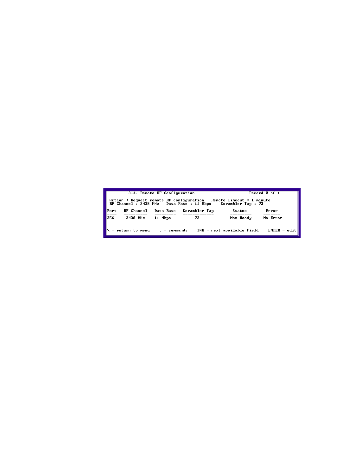
Remote RF Configuration.................................................................36
Using Remote RF Configuration...................................................36
Confirming RF Changes on the Base ............................................37
Confirming RF changes on the SkyWay Subs...............................37
Confirming RF changes on the SkyMate Subs..............................37
Bandwidth Management...................................................................38
Configuring Bandwidth Management ...........................................39
Verifying Bandwidth Management Changes.................................39
SNMP..................................................................................................40
Setting Network Management Security Parameters......................40
SNTP...................................................................................................41
SNTP Configuration ......................................................................42
Changing SNTP Modes .................................................................42
BootP/DHCP Server-Client Protocols .............................................43
Configuring BootP/DHCP on SkyWay-Net..................................43
Configuring BootP and DHCP on SkyMate..................................47
File Transfer Utilities ...............................................................48
TFTP...................................................................................................48
TFTP Server Configuration ...........................................................49
Configuring Skyway as TFTP Server............................................50
Configuring Skyway as TFTP Client.............................................51
Y Modem ............................................................................................51
X Modem ............................................................................................52
ix

Table of Contents
Chapter 3:Monitoring SkyWay Series Network....53
Monitoring Ports ......................................................................53
RF Port................................................................................................53
Connecting the RF Link....................................................................53
Checking the WCOPP-AP Configuration......................................54
Checking the WCOPP-AP Status..................................................54
Checking the WCOPP Sub Port Status..........................................55
Checking the RF Port Status..........................................................55
Monitoring Traffic on your RF Link...............................................56
ALC/ADC ...........................................................................................61
Ethernet ..............................................................................................61
Monitoring the Ethernet Port Status ..............................................62
Monitoring the Ethernet Transceiver Status..................................63
Routing.....................................................................................63
IP Status..............................................................................................63
Checking IP Protocol Status..........................................................63
Checking IP Address Table ...........................................................65
Checking the IP Address Forward Table.......................................65
Checking the RIP Status ...................................................................66
Bridging....................................................................................67
Checking Spanning Tree Status and Bridge Status........................68
Checking Spanning Tree Port Status .............................................68
Checking Transparent Bridging Table Status................................69
Checking Bridge Port Status/Statistics..........................................69
Management.............................................................................70
Systems Tasks - Status & Control....................................................70
Task Status and Control Screens ...................................................70
Task Interdependencies..................................................................70
Checking SNMP Status and Trap History......................................71
SNMP Status..................................................................................71
x

SkyWay Series Multi-Point Operator’s Guide
SNMP Trap History.......................................................................73
Protocols & Applications .........................................................73
TCP Statistics.....................................................................................73
Checking UDP Status ........................................................................74
IGMP...................................................................................................75
Checking IGMP Activity...............................................................75
Checking ICMP Status...................................................................76
Checking BOOTP and DHCP Status...............................................77
Monitoring BOOTP Status ............................................................77
Monitoring DHCP Declines...........................................................78
Monitoring DHCP Statistics..........................................................78
Monitoring DHCP Client Protocol Status .....................................79
Monitoring SNTP ...............................................................................79
Monitoring the ARP Cache ...............................................................80
Appendix A:RunTime & Bios Application Menu Trees81
Run Time Application Menu Tree ...........................................81
Bios Application Menu Tree....................................................84
Appendix B:SNMP - MIB & Trap Messages........87
MIB Definitions .......................................................................87
SNMP Traps.............................................................................87
Appendix C:Glossary and Basic Concepts............89
Glossary of Terms and Abbreviations......................................89
xi

Table of Contents
Basic Concepts.........................................................................94
Connection Types.....................................................................99
Antennas...................................................................................99
Protocols.................................................................................102
Equipment ..............................................................................103
Site Survey .............................................................................103
Index ....................................................................107
xii

Preface
This operator’s guide is designed to help you configure and operate your SkyWayNet Wireless Bridge/Router.
Intended Audience
This document contains information required for configuring and operating for
your SkyWay-Net Wireless Bridge/Router. The information in this manual written
for a technical audience that meets the following requirements:
• You are functioning in an Information Services or Building Facilities
capacity.
• You have more than one year’s experience with networking, either
wireless or traditional.
• You are familiar with basic networking concepts such as bridging, IP
routing, WAN protocols, etc.
• You are familiar with your LAN or WAN’s topology, configuration, and
design.
• If you will be using Simple Network Management Protocol to manage
SkyWay, you are familiar with the protocol’s terms and usage.
• You are familiar with basic RF/wireless network design, even if you are
not familiar with the particulars of any specific system.
Note If you do not meet these requirements, we recommend that you hire a
consultant to assist you with configuring and operating your SkyWay-Net
and network.
xiii

Preface
Using This Guide
This guide contains the following chapters and appendixes:
• Chapter 1: Getting to Know Your SkyWay Series
Provides an overview of features and physical elements of the SkyWayNet Wireless Bridge/Router, including how to use the Administrative
Console.
• Chapter 2: Configuring Your SkyWay Series Unit(s)
Discusses how to configure SkyWay-Net as a bridge, a router, or both,
including instructions for setting up base and substations.
• Chapter 3: Monitoring SkyWay Series Network
Describes the SkyWay-Net utilities you can use to monitor transmission
and routing performance.
• Appendix A: RunTime & Bios Application Menu Trees
This appendix provides a list of the SkyWay-Net Runtime application
menu structure, including all screen titles and numbering.
• Appendix B: SNMP - MIB & Trap Messages
This appendix lists the standard and enterprise SNMP traps.
• Appendix C: Glossary and Basic Concepts
This appendix lists and defines important terms used in this manual.
• Index
xiv

Chapter 1: Getting to Know Your SkyWay Series
This book is the second guide in the SkyWay Series documentation. It focuses on
the operation of the SkyWay Series of products: SkyWay-Net and SkyMate
wireless bridge/routers.
For installation and set up information on SkyWay-Net and SkyMate products,
refer to the SkyWay Series Multi-Point Installation Guide for detailed instructions.
For basic information, refer to the SkyWay-Net Quick Start Guide or the SkyMate
Quick Start Guide. These guides are for quick reference use and contain the basic
information required to set up the unit.
This chapter focuses on basic access and interface information for the SkyWay
Series bridge/router units. This information was discussed in the SkyWay Series
Multi-Point Installation Guide. If you are familiar with the SkyWay console,
commands, and interface, skip this chapter and proceed to “Chapter 2:
Configuring Your SkyWay Series Unit(s)” on page7.
This information is described in the following sections:
General Description .......................................................... 1
Navigating Through Menus and Screens.......................... 2
Dot Commands ................................................................. 3
General Description
SkyWay Series -- The Long Distance Connection. The SkyWay Series of
bridge/routers: SkyWay-Net and SkyMate, allow you to set up high-speed, wide
area networks over long distances. These products give you the power to establish
LAN-to-LAN connections over distances of up to 30 miles (48 km) using SkyWay-Net to SkyWay-Net and up to 10 miles using SkyWay-Net to SkyMate - with
superior performance.
Point-to-Point or Multi-Point Application. These units can be used anywhere
high speed data transfer or Internet access is required including corporate offices,
educational campuses, healthcare facilities, manufacturing, or retail.
Configurations can be set for Point-to-Point or Multi-Point applications.
1
Chapter 1: Getting to Know Your SkyWay Series
Each SkyWay-Net can function as a base station (central site) or a substation
(remote site). The SkyMate functions as substation and must have a SkyWay-Net
as the base station.
Remote Operations. With all SkyWay Series units, all management functions,
monitoring, and software updates can be performed remotely from any desired
location.
Support. Solectek offers a world-wide network of factory trained resellers as well
as onsite and online technical assistance programs.
Navigating Through Menus and Screens
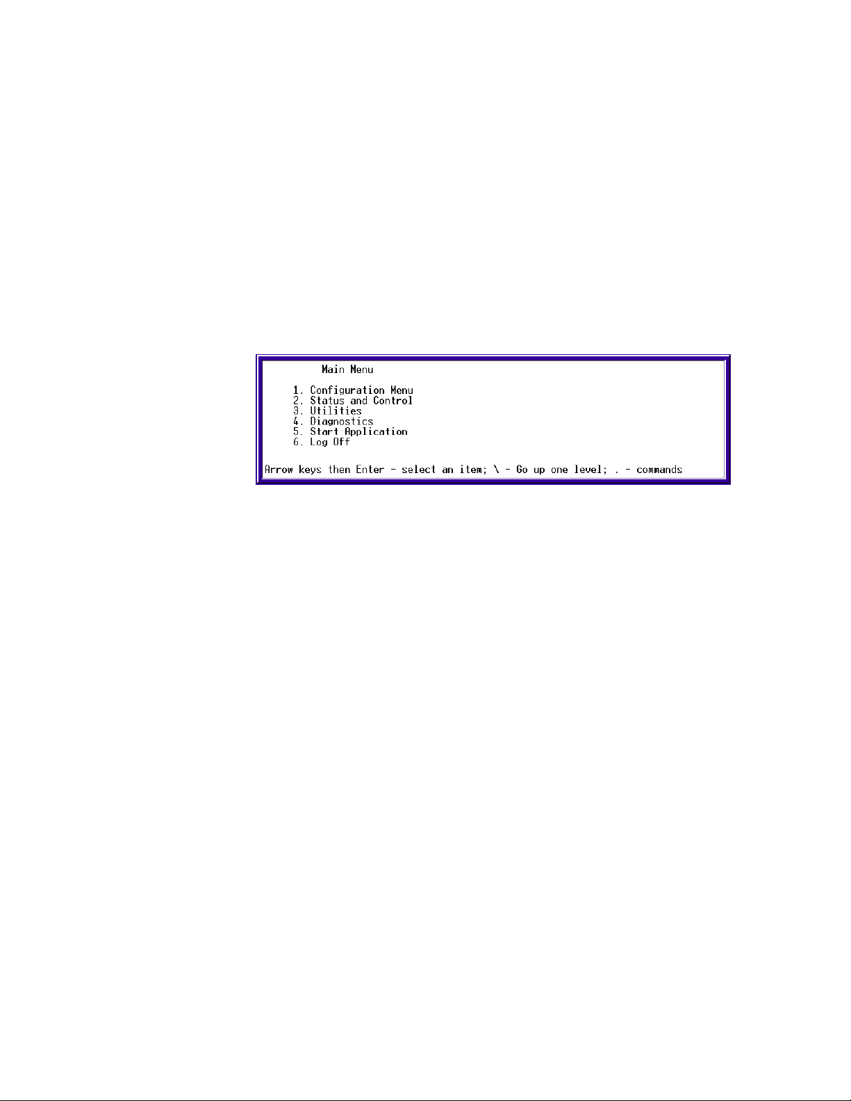
Once you have opened the console, the Main Menu appears, as shown in the
following:
Use the keys in the following table to navigate through the menus:
To… Press This Key…
Move down or up through menu
options
Move through list of field entries
Select an item or edit a field Enter
Go up one menu level
Move between fields Tab key, Up or Down Arrows
Enter a command
Go directly to a particular screen if
you know the screen number
Down or Up Arrows
Right- or Left-Arrows or Space Bar
\ (Backslash)
.(dot) followed by the command (see Dot
Commands in the following section).
From the Main Menu, enter the screen number.
From all other screens, press . (period/dot) and
type the number of the screen. The screen title
appears above the number, e.g.,
System Configuration
>11
If this is the screen you want, press Enter.
2

Dot Commands
SkyWay Series Multi-Point Operator’s Guide
You can access commands from all non-menu screens. When they are available,
.commands appear at the bottom of the screen. Press . to display the command
line which lists the available commands for that screen, that is, not all commands
are available on every screen. The following table describes the commands:
Dot Cmnd Command Description
.a
.c
.f
.g
.h
.m
.n
.p
Add Add a new record to a table
Cancel Cancel any changes made to this screen before
you press .W
Flush Flushes table entries. Available for these screens:
• 2.1.3 Error Log Screen
• 2.3.4 Transparent Bridging Table
• 2.4.1.5 ARP Table
This is functionally the same as accessing the 3.3
Flush utility, which allows you to flush one or more
of the preceding tables at a time.
Go To Go to the specific table record by key value (for
example, port number).
Help
Go to the HELP screen, which lists arrow keys and
. commands.
Monitor Monitor Mode ON or OFF. Monitor mode
continuously refreshes the data displayed, allowing
you to see the system operating in real time.
Next Display the next record in a table.
Previous Display the previous record in a table.
.r
.w
.z
Read Update screen data (refresh).
Write Save screen data to the database (write). This is
usually required after you make a configuration
change before the change takes affect.
Zero Clears the statistics on the current status screen
(zero).
.(dot) Use to go to a particular screen number. Type .
(dot), then type the screen number you want to go
to (for example, 224) and press Enter. You cannot
use this method at a menu screen.
3

Chapter 1: Getting to Know Your SkyWay Series
How Screens Display Information
Configuration and status records are displayed in the following formats:
• As a static variable
• As a table with many rows or records
• As a table with one row or record
Screens Displaying One Record. On some screens, one row or record of the
table appears at a time (see screen 2.2.1. for an example). All of the data displayed
is from a single record in the table. The record you are looking at is indicated at
the top right of the screen (for example, Record 1 of 2 means you are looking at
the first record (row) of data in a two-record table). Press .N to view the next
record or .P to see the previous record.
Scrolling Screens. Some screens display information that does not fit on one
screen. Press .N to see the next screen, or .P for the previous screen.
Common Rows. Common fields appear only on screens containing tables with
many rows. Common rows display in the 4-row space above the command line at
the bottom of the screen. These rows display field data for the record at the cursor
position.
Editing Fields
Fields that you can edit or configure display the current value with a blinking
cursor. To change the value, position the cursor on the field and press Enter or just
begin editing the field.
Field Types
The types of field data in a record are:
• Numeric - Enter a number within a certain range. If the number you enter
is outside the range, the field redisplays the original value and the cursor
remains on the field.
• Text - Enter alphanumeric characters up to the maximum length allowed.
• Select from a List - Select values using the arrow keys or Space Bar to
scroll through the list of valid entries for that field (brackets appear around
the field value).
To finish editing the field, press Enter to remove brackets and accept the new
value, or just move to another field with the arrow keys.
To save all changes, type “.w” to write the changes to the database.
To back out all changes, type “.c” to cancel.
Note: Access to certain screens and fields may be restricted for certain users.
4

SkyWay Series Multi-Point Operator’s Guide
Saving Configuration Changes
Save any changes you make by using the Write “.w” command. This updates the
database immediately, the screen refreshes and displays the new values.
Sometimes you must cycle the port or reset the unit for the changes to take affect.
(See “Changes that Require Cycling or Resetting” on page5.)
If you make changes to a screen and try to leave it without saving, the screen
warns you “Data has been modified. Write or Cancel changes.” Type .w to write
(or save) the modification or .c to cancel the modification, remove the warning
and return to the screen.
Note: Sometimes the Write and Cancel commands do not appear in the list of
commands (at the bottom of screen) unless you make a change to a field.
Changes that Require Cycling or Resetting
Cycling a port
If you edit any port-level configuration parameters, you must cycle the port for the
changes to take affect immediately (for example, those in the 1.2 menu tree).
To cycle the port:
1. Go to 2.2.1 Generic Port Status and Control.
2. Type 3, press Enter and type “.g” (or .n until the port 3 is displayed).
3. Set the Administrative Status field to Cycle.
4. Type “.w” to execute the command.
Cycle evacuates the port, reinstalls the driver, reads the database, and brings
up the port.
Resetting the Unit
If you download an update to the SkyWay Series software using the file transfer
utilities or change any global parameter (enabling or disabling bridging/routing),
you must reset the unit.
Caution: If you are resetting the base station, all substation links also go
down.
To reset the unit:
1. Go to the Main Menu.
2. Type 5 (Start Application).
3. Choose Run Time Application as the Application to Start.
4. Type “.w” to execute the command.
This reloads the updated database containing the new configuration
parameters.
5

Chapter 1: Getting to Know Your SkyWay Series
6

Chapter 2: Configuring Your SkyWay Series Unit(s)
You configure your SkyWay Series Bridge/Router from either local or remote
access. The local console provides a menu-based user interface you can use to set
SkyWay Series configuration features and run diagnostics.
This chapter provides the following sections for configuring and managing the
SkyWay Series Bridge/Router:
Basic Configuration .......................................................... 8
Advanced Configuration................................................. 27
Network Management ..................................................... 31
File Transfer Utilities...................................................... 48
Each of these section are divided into subsections. These subsections are “taskoriented” with step-by-step procedures designed to guide you through the
configuration process. The following describes the basic content of each major
section in this chapter:
Basic Configuration. This section discusses the basic aspects of configuring the
unit(s) for operation. These include:
• User Access
• Accessing the SkyWay Series Bridge/Router
• Remote Access Using Telnet
• WCOPP-AP Modes
• Bridging and Routing
• ALC/ADC
7

Chapter 2: Configuring Your SkyWay Series Unit(s)
Advanced Configuration. This section discusses protocols the SkyWay Series
units use, including:
• RIP
• IGMP
Network Management. This section focuses on methodology to maximize your
wireless network. This includes:
• Filters
• Remote RF Configuration
• Bandwidth Management
• SNMP
• SNTP
• BootP/DHCP Server-Client Protocols)
File Transfer Utilities. This section discusses how to configure utilities for
transferring files to and from your unit(s). This includes:
• TFTP
• X Modem
Basic Configuration
This section of the chapter discusses the basic requirements to configure your
SkyWay Series Bridge/Router units, including your SkyWay-Net Base unit,
SkyWay-Net Substation unit(s), and your SkyMate Substation units. Basic
configuration includes:
Configuring User Access
There are two types of user access for the SkyWay-Net:
Super Users. Super users have the capability of configuring and viewing all the
screens of the SkyWay unit. This is a System Administrator level; once this level
is granted to a user, they can change all settings.
• Y Modem
• Configuring User Access
• Accessing the SkyWay Series Bridge/Router
• Remote Access Using Telnet
• WCOPP-AP Modes
• Bridging and Routing
• Super
• Standard
Standard Users. Standard users can view most screens - with a few exceptions.
Screens that are viewable to a Standard user does not mean Standard user can
modify the configuration.
8

SkyWay Series Multi-Point Operator’s Guide
Adding a User
The Add a User (1.1.3.1) screen allows Super users to add additional users, either
Standard or Super. To access this screen, you must have an access level of Super.
Note: This screen is not accessible via SNMP.
1. Go to Add a User screen (1.1.3.1)
2. Under Username, enter the user's name.
3. Under Password, enter the password of the user.
4. Under Confirm Password, re-enter the password of the user.
5. Under User Level, Select Standard or Super by typing the right arrow key.
6. Type “.w” (Write) when finished.
To confirm the user has been added:
7. Go to the User screen (1.1.3.2).
8. All the users should be listed with their user level.
Viewing Users
The User (1.1.3.2) screen can be viewed by both Standard and Super users.
However, Standard user can only view Standard users in this screen. Super user
can view and modify both Standard users and Super users.
Changing a User’s Password
1. Go to the User screen (1.1.3.2).
2. Under Password of the specific user, type the new password.
3. Under Confirm Password of the specific user, re-enter the new password.
9

Chapter 2: Configuring Your SkyWay Series Unit(s)
Accessing the SkyWay Series Bridge/Router
There are two ways to connect to your SkyWay Series:
• Console
• Remote
The following two section describe these two methods and how to use them.
Local Access using the Console
Accessing the console is a direct connection. This configuration is where a
terminal directly connected to the unit's RS-422 port. This is called the local
console - it allows you to directly access all of the configuration and management
screens. There are two screens associated with the set-up of this connection:
• Serial Port Configuration
• Serial Port Transceiver Configuration
Serial Port Configuration
Settings for this screen are:
Title Settings Description
Port Number 1 The serial port number is 1
Configuration Status On-line or Offline Whether this port
configuration initializes upon
reset. On-line means the
port comes up as a serial
port when the unit is reset;
Off-line means the port does
not initialize upon reset.
Buffers 80 Serial port buffers
Transmit Buffers 18 Serial port transmit buffers
Receive Buffers 10 Serial port receive buffers
Maximum Frame Size 512 Largest frame that can be
transmitted via the serial
port.
10
SkyWay Series Multi-Point Operator’s Guide
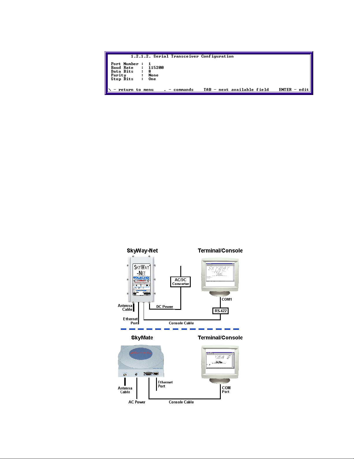
Serial Port Transceiver Configuration
Settings for this screen are:
Field Title Settings Description
Port Number 1 The serial port number is 1
Baud Rate 115200 The transfer or baud rate of
the local serial port.
Data Bits 8 The number of data bits for
the serial port.
Parity NONE The parity setting for the
serial port.
Stop Bits One The number of stop bits for
the serial port.
Connecting the Console
The following illustration shows the cabling connections from the SkyWay-Net to
the Console or SkyMate to Console.
11

Chapter 2: Configuring Your SkyWay Series Unit(s)
Opening a Console session using Hyperterminal
Once your system is connected, open a HyperTerminal™ session on your PC.
In MS-Windows®, choose: Start/Programs/Accessories/Communications/
HyperTerminal/Hypertrm.exe.
In HyperTerminal, create and name a new connection for the attached SkyWay-
Net unit, (for example, SkyWay-Net Base).
Select the applicable COM port (COM1, COM2...).
Change Settings to the following:
• Bits per second = 115200
• Data Bits = 8
• Parity = None
• Stop bits = 1
• Flow Control = None
Under the File Menu, select Properties. Click on the Settings Tab and set
Emulation to VT100.
Save, exit, and restart your HyperTerminal session.
Press Enter and login (user & password = solectek).
Remote Access Using Telnet
Telnet is the standard Internet application protocol for remote login. It provides
the encoding rules to link a user's keyboard/display on a client with a command
interpreter on a remote server system.
Telnet uses a single TCP connection, and its normal data stream (“Network
Virtual Terminal” or “NVT” mode) is 7-bit ASCII with escape sequences to
embed control functions.
There is no user console screen for this task on SkyWay. Use the following steps
to access your SkyWay Series wireless network using Telnet.
1. SkyWay Telnet server should already have a working Ethernet or RF IP
address.
2. From a remote Telnet client log on to the Telnet server host IP address.
3. It should connect the Telnet client to the Telnet server.
4. The SkyWay Telnet server supports a single Telnet session.
12

SkyWay Series Multi-Point Operator’s Guide
WCOPP-AP Modes
There are four modes of operation in WCOPP-AP you can set for each SkyWay
Series unit (SkyWay-Net or SkyMate):
• Standby (default)
• Standard
• Manual
• Promiscuous
Standby
In Standby mode (default mode), the SkyWay-Net base will ask for permission to
add a “searching” sub-station to the network. This mode adds a checkpoint before
accepting new members to the base's network. This checkpoint can be
accomplished by the base-station in one of two ways: manual or automatic.
Manual checking will require operator intervention in accepting or declining the
sub-station. Automatic checking will attempt to verify the existence of the
“configuration” file to be downloaded to the sub-station for the SkyMate's of
“plug-n-play” feature. If this configuration file exists, then the substation will be
accepted. If this configuration file does not exist, then the substation will be
declined.
Note: The configuration file used for “plug-n-play” follows the naming
convention as follows. Using the lower 10 hex digits of the 12 hex digit
RF MAC address of the sub-station to be added, append the upper 7 to the
letter “C” for the prefix and the remaining lower three hex digits for the
suffix. Thus, a MAC address with the following value,
“0x123456789ABC”, would have the following configuration file name,
“C1234567.ABC”.
Standard
In this mode, the SkyWay-Net base station will only accept sub stations that have
specifically been added to the base station's acceptance list (controlled by
substation's MAC address). This mode offers a balance between easy
configuration and security being that the base will easily add specific, new
members to its network.
Manual
In this mode, the user manually configures both the SkyWay-Net base station and
the Skymate sub station in order for a wireless link to be established. Specifically,
the RF channel, scrambler tap, and bridging or routing are configured on each end
of the link. This mode requires the most configuration by a installer, but it can be
the most reliable way to configure your network if you have specific desired set of
network settings.
13

Chapter 2: Configuring Your SkyWay Series Unit(s)
Promiscuous
In this mode, the SkyWay-Net base station will allow any Skymate substation
within its range to connect to the base's network. This process is as follows:
• The substation turns on and begins channel searching starting at the lowest
frequency.
• The first base found set to promiscuous mode would accept the substation
and add it to its network.
Note: Careful consideration should be given to this mode as environments with
overlapping coverage of base stations may result in an over-used base (at
lower frequency) and under-used base(s) (at higher frequency).
Configuring the SkyWay-Net as a Base Station
1. Invalidate the RF Diagnostic Port (if present).
a. Go to the RF Diagnostic Port Configuration screen (1.2.3.2).
b. Under Record Type field, change Valid to Invalid and press Enter.
c. Type “.w” to write the record. Once the Write command is executed, your
screen will change to blank entries, as shown in the following:
14
2. Configure the RF Transceiver Settings.
a. Go to the RF Transceiver Configuration screen (1.2.3.3)
b. Under Frequency, change the value to the desired frequency then press
Enter.
c. Under RF Data Rate, change the value to the desired rate, then press Enter.
Note: The Scrambler Tap field is currently being updated.
d. Under Modulation, select either MBOK or CCK (SkyMate only supports
CCK). For this example, we will use the SkyMate configuration.
e. Type “.w” to write the record. Depending on your settings, your screen
should look like the following:

SkyWay Series Multi-Point Operator’s Guide
3. Configure the RF Base Port.
a. Go to the RF Base Port Configuration screen (1.2.3.1.1).
b. Type “.a” to add a base port configuration. You should see the following:
4. Configure the appropriate WCOPP-AP mode.
Standby Mode (default)
a. Under WCOPP Mode field, change to Standby Mode and press Enter.
b. Type “.w” to write the record.
c. Proceed to Configuring the SkyWay Net as a Sub station or Configuring
the SkyMate Substation.
d. When finished configuring the SkyWay-Net or SkyMate Substation, go to
the WCOPP-AP Status screen (2.6.5).
e. Type “.r” to view each Sub station that is trying to associate with the Base
station.
f. Under the Association Control field, change to Accept and press Enter.
g. Type “.w” to write the record.
h. Repeat procedure f and g for each additional Substation that you want to
accept.
Standard Mode
a. Under WCOPP Mode field, change to Standard Mode and press Enter.
b. Type “.w” to write the record.
c. Go to the WCOPP-AP Configuration screen (1.2.3.1.3).
d. Type “.a” to add a Substation configuration.
e. Under MAC Address insert the RF MAC address of the Substation.
f. Type “.w” to write the record.
g. Repeat steps d through f for each additional Substation.
15

Chapter 2: Configuring Your SkyWay Series Unit(s)
Manual Mode
a. Under WCOPP Mode field, change to Manual Mode and press Enter.
a. Type “.w” to write the record.
b. Go to the WCOPP-AP Configuration screen (1.2.3.1.3).
c. Type “.a” to add a Sub station configuration.
d. Under MAC Address insert the RF MAC address of the Substation.
e. Under Logical Port Number insert the logical port number of the
Substation starting with 256.
f. Type “.w” to write the record.
g. Repeat procedures d through g for each additional Substation and
increment the logical port number.
Promiscuous Mode
Note: This setting is recommended for use where there is only one SkyWay-
Net network - other SkyWay-Net networks may cause system problems.
a. Under WCOPP-AP Mode field, change to Promiscuous Mode and press
Enter.
b. Type “.w” to write the record.
5. Configure SkyWay-Net Base in Bridging or Routing Network
To Configure SkyWay in Bridging Network, go to “Configuring for Bridging
Only” on page23.
To Configure SkyWay in Routing Network, go to “Configuring for Routing
Only” on page20.
Configuring the SkyWay-Net as a Substation.
1. Invalidate the RF Diagnostic Port (if present).
a. Go to the RF Diagnostic Port Configuration screen (1.2.3.2).
b. Under Record Type field, change Valid to Invalid then press enter.
c. Type “.w” to write the record.
2. Invalidate the RF Base Port (if present).
a. Go to the RF Base Port Configuration screen (1.2.3.1.1).
b. Under Record Type field, change Valid to Invalid then press Enter.
c. Type “.w” to write the record.
3. Configure the RF Transceiver Settings (only for Manual Mode).
16
a. Go to the RF Transceiver Configuration screen (1.2.3.3).
b. Under Frequency, change the value to the same frequency as the Base
station and press Enter.
c. Under RF Data Rate, change the value to the desired rate and press Enter.

SkyWay Series Multi-Point Operator’s Guide
Note: The Scrambler Tap field is currently being updated.
d. Under Modulation, select either MBOK or CCK to match the Base.
e. Type “.w” to write the record.
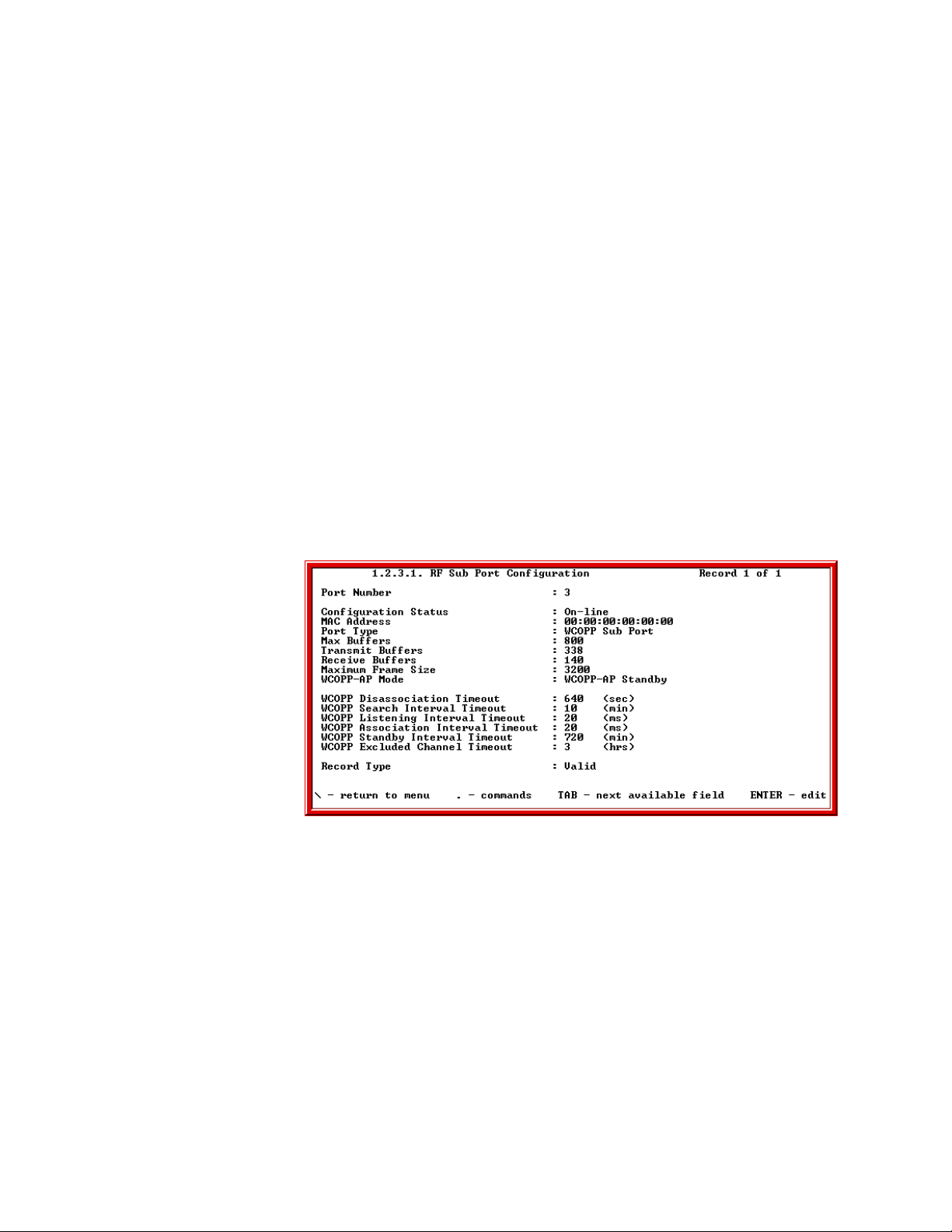
4. Configure the RF Sub Port.
a. Go to the RF Sub Port Configuration screen (1.2.3.1.2).
b. Type “.a” to add a Sub port configuration.
c. If the Base is in Manual Mode, change the WCOPP Mode field to Manual
Mode.
d. If the Base is in Standard or Promiscuous Mode, change the WCOPP
Mode field to Standard Mode.
e. Type “.w” to write the record.
f. If the Base is in Standby Mode, change the WCOPP Mode field to
Standby Mode.
g. Type “.w” to write the record.
5. Configure SkyWay-Net Sub in Bridging or Routing Network.
To Configure SkyWay in Bridging Network, go to “Configuring for Bridging
Only” on page23.
To Configure SkyWay in Routing Network, go to “Configuring for Routing
Only” on page20.
Configuring SkyMate Substation(s).
1. Invalidate the RF Diagnostic Port (if present).
a. Go to the RF Diagnostic Port Configuration screen (1.2.3.2).
b. Under Record Type field, change Valid to Invalid and press Enter.
c. Type “.w” to write the record and you should see the following:
SkyMate Example Screen
2. Configure the RF Transceiver Settings (only for Manual Mode).
17
Chapter 2: Configuring Your SkyWay Series Unit(s)
a. Go to the RF Transceiver Configuration screen (1.2.3.3).
b. Under Frequency, change the value to the same frequency as the Base
station and press Enter.
c. Under RF Data Rate, change the value to the desired rate and press Enter.
Note: The Scrambler Tap field is currently being updated.
d. Type “.w” to write the record.
3. Configure the RF Sub Port.
a. Go to the RF Sub Port Configuration screen (1.2.3.1)
b. Type “.a” to add a Sub port configuration.
c. If the Base is in Manual Mode, change the (SkyMate) WCOPP Mode field
to Manual Mode.
d. If the Base is in Standard or Promiscuous Mode, change the (SkyMate)
WCOPP Mode field to Standard Mode.
e. If the Base is in Standby Mode, change the (SkyMate) WCOPP-AP Mode
field to Standby Mode. For this example, we will set the SkyMate to
Standby (default setting) mode.
f. Type “.w” to write the record and you should see the following:
SkyMate Example Screen
4. Configure SkyMate in Routing or Bridging Network. To Configure SkyMate
in Routing Network, proceed to “Configuring for Routing Only” on page20.
To Configure SkyMate in Bridging Network, proceed to “Configuring for
Bridging Only” on page23.
Bridging and Routing
18
The SkyWay-Net Bridge/Router can function as a bridge or router. When a packet
arrives at the bridge, SkyWay-Net examines it and determines its protocol type.
The packet is then forwarded or discarded, depending on the following functions
enabled on the bridge:
SkyWay Series Multi-Point Operator’s Guide
• Routing only - Only IP suite packets are forwarded; all other protocols are
discarded
• Bridging only - All packets are forwarded without regard to protocol
If IP packets are sent to the bridge itself (its own IP address), it will accept them
even if it is configured for bridging only.
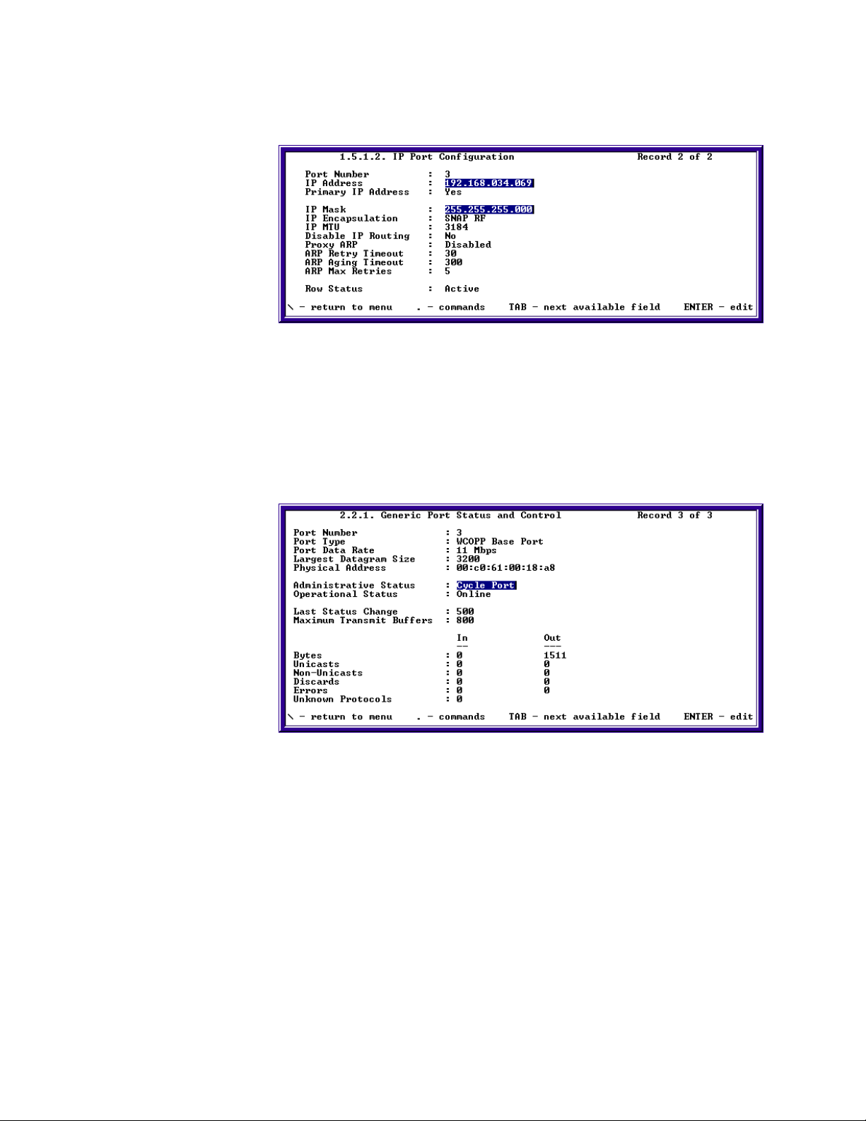
IP Routing
IP routing is a global parameter. It is disabled by default. If you choose to enable
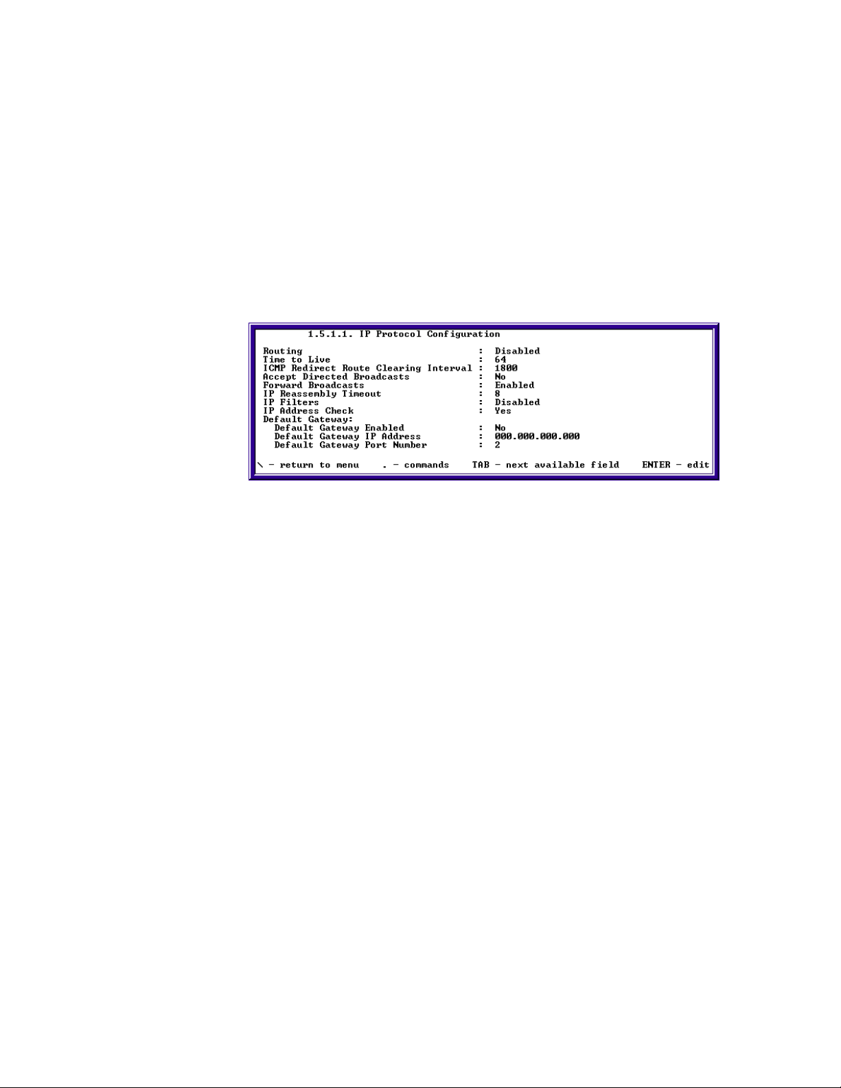
routing, you must disable bridging. Also, you cannot configure routing on a portby-port basis.The IP Protocol Configuration screen is where you begin the process
of configuring for Routing Only.
The IP Protocol Configuration screen 1.5.1.1 has nine setting:
• Routing
• Time to Live
• ICMP Redirect Route Clearing Interval
• Accept Directed Broadcasts
• IP Reassembly Timeout
• IP Filters
• Default Gateway
- Default Gateway Enabled
- Default Gateway IP address
- Default Gateway Port number
The following section describes each setting and their functions.
Routing. Enable or Disable. This field enables or disables IP routing on the
system. If routing is disabled on this screen, it is disabled for all ports. If this
parameter is changed, the unit must be reset.
Time to Live. 1-100 seconds. Specifies the number of hops a packet can be
forwarded before it is discarded.
ICMP Redirect Route Clearing Interval. 1-65535 seconds. The interval of
time, in seconds, in which routes learned from ICMP redirect messages are
cleared.
19
Chapter 2: Configuring Your SkyWay Series Unit(s)
Accept Directed Broadcasts. Yes or No. This field allows receiving directed
broadcast messages. When set to (No), messages will be discarded.
Forward Broadcasts. Enable or Disable. Enable or disable indicates whether
directed IP broadcast messages are forwarded.
IP Reassembly Timeout. 1-15 seconds. Determines how many seconds to wait
before discarding a packet when all fragments have not yet arrived.
IP Filters. Enable or Disable. Enables or disables IP Filtering.
Default Gateway. Next three fields determine if default gateway is set or not.
Default Gateway Enabled. Yes or No. Set to yes to set a default gateway. If this
field is set to no it will remove a default gateway entry from the forwarding table.
Default Gateway IP Address. Enter the IP address to send IP datagrams for
which no route was found.
Default Gateway Port Number. port number 1-9. Use the base port number
when forwarding IP datagrams with unknown routes.
Configuring for Routing Only
When you configure for routing, you must also disable bridging. Use the
following procedures to enable routing and disable bridging.
Enable Routing
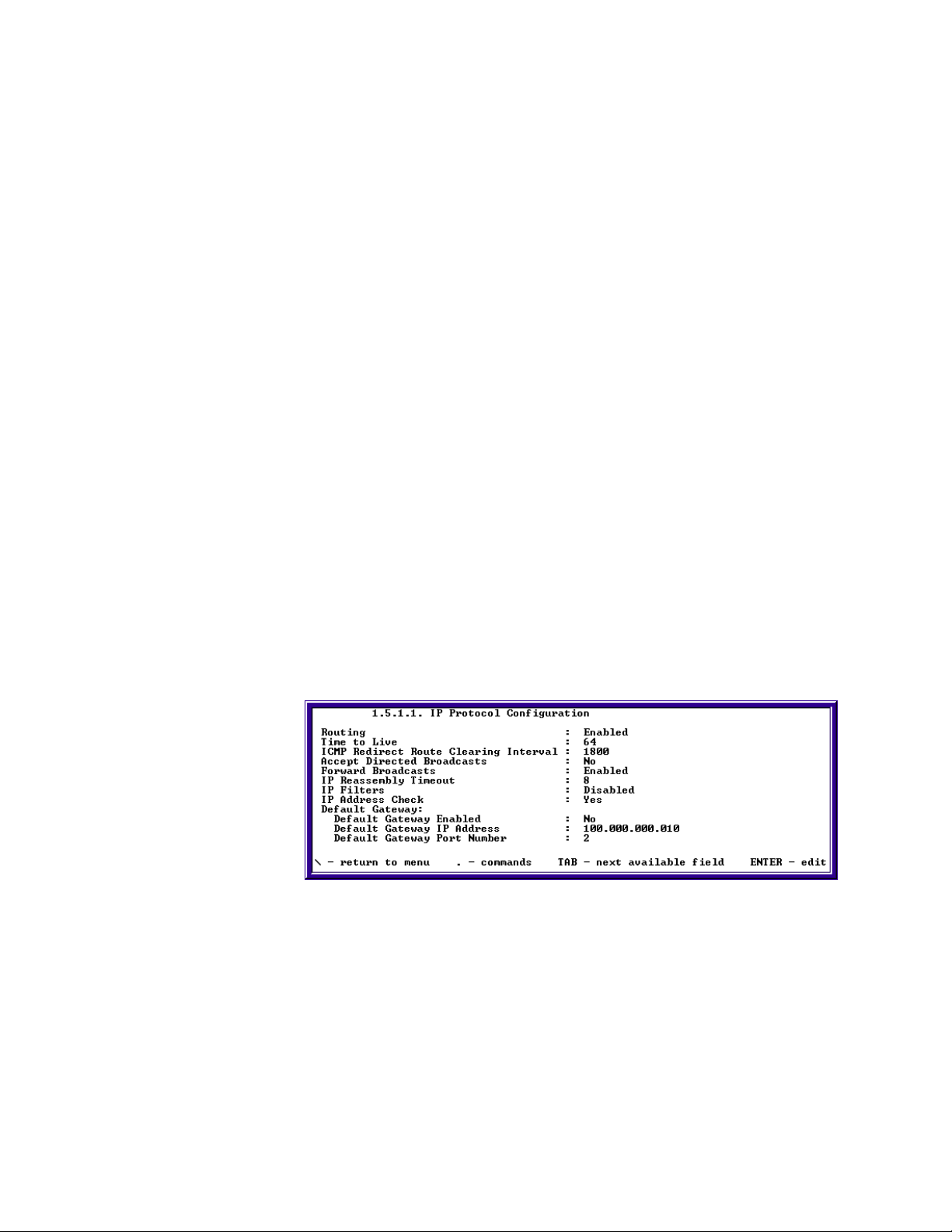
Use the 1.5.1.1 IP Protocol Configuration screen to enable routing.
1. For SkyWay-Net BASE - use the following settings to configure for Routing.
a. Set Routing field to Enable.
b. Type “.w” to write the changes, and you should see the following:
2. For SkyMate SUBSTATION, use the following settings to configure for
Routing.
a. Set Routing field to Enable.
b. Set Default Gateway Enabled to yes.
c. Assign the IP address of the base in default gateway IP address.
20
d. Set the default gateway port number to 3.
SkyWay Series Multi-Point Operator’s Guide
e. Type “.w” to write changes, and you should see the following:
SkyMate Example Screen
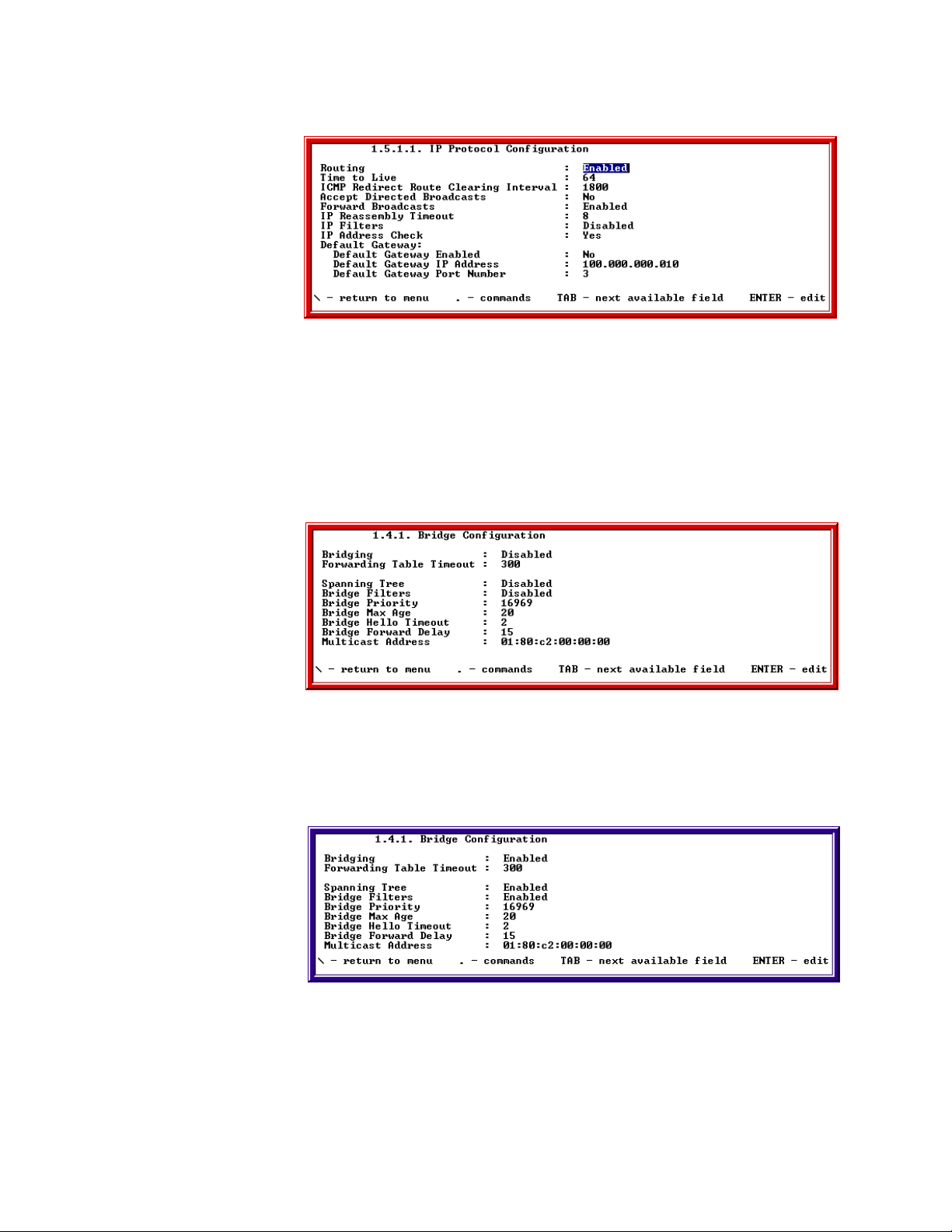
Disable Bridging
When you choose Routing Only, you must disable Bridging. Use the 1.4.1 Bridge
Configuration screen to disable bridging.
1. For disabling bridging, go to screen 1.4.1
2. Set Bridging field value to disabled.
3. Type “.w” to write changes and you should see the following:
SkyMate Example Screen
For more information on Bridging, proceed to the next section.
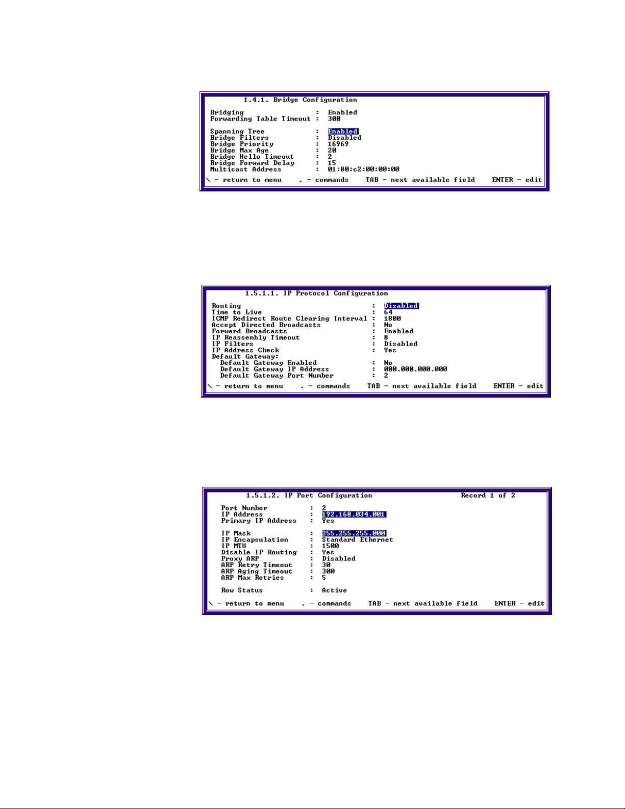
Bridging
When you choose to enable Bridging, you must disable Routing. The 141 Bridge
Configurations is where you begin the Bridging Only process.
21

Chapter 2: Configuring Your SkyWay Series Unit(s)
The Bridging Configuration screen has the following fields:
• Bridging
• Forwarding Table Timeout
• Spanning Tree
• Bridge Filters
• Bridge Priority
• Bridge Max Age
• Bridge Hello Timeout
• Bridge Forward Delay
• Multicast Address
The following sections describe each field, their settings and functions.
Bridging. Enabled or Disabled. Enables or disables bridging on the system. If
you disable bridging on this screen, it is disabled for all ports. If you change this
parameter, you must reset the unit. Bridging supersedes Spanning Tree function,
i.e., if you disable Bridging - you also disable Spanning Tree.
Spanning Tree. Enabled or Disabled. Spanning Tree allows the bridge to
determine which ports to shut down (Blocking mode) and break loops that occur
in the topology. It uses an algorithm that calculates the best route and determines
which ports will be included (or excluded) in the Spanning Tree. If the Spanning
Tree algorithm sets the port state to Blocking, the port will not allow duplicate
frames to be transmitted (caused from multiple paths or loops in the active
topology of the bridge). If you disable bridging, you also disable Spanning Tree. If
Spanning Tree is disabled and bridging is enabled, you can set the ports manually.
22
Fowarding Table Timeout. Range of seconds: 10-1000000. The timeout period
in seconds for aging out dynamically-learned forwarding information.
Bridge Filters. Enabled or Disabled. All frames can be checked against the
filters defined in the system.
Bridge Priority. 32768. This allows you to influence the choice of root bridge
and designated bridge. A lower numerical value means the bridge is closer to
becoming the root, thereby change the topology of the Spanning Tree.
Bridge Max Age. 20. The amount of time in seconds the bridge waits before it
discards configuration BPDUs.
Bridge Hello Timeout. 2. The amount of time in seconds before the bridge
issues a configuration BPDU.
BPDU Forward Delay. 15. The amount of time a port waits before going into a
forwarding state.
Multicast Address. The spanning tree multicast address contained in the
configuration BPDU (message). This is the MAC address of packets intended for a
bridge.
SkyWay Series Multi-Point Operator’s Guide
Configuring for Bridging Only
Ensure unit is configured as a Base or Sub. If not, see “Configuring the SkyWayNet as a Base Station” on page14, “Configuring the SkyWay-Net as a
Substation.” on page16 or “Configuring SkyMate Substation(s).” on page17.
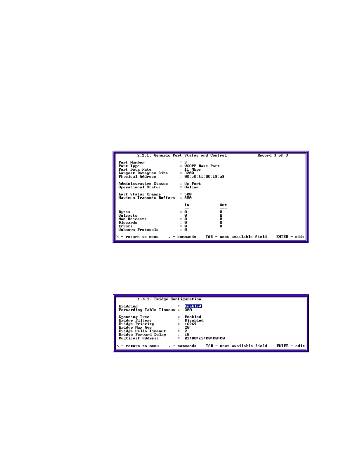
1. Cycle RF Port
a. Go to screen 2.2.1 Generic Port Status and Control.
b. Type “.n” and press Enter twice to change to the RF port.
The port number should be 3.
The port type should be either WCOPP Base Port or WCOPP Sub Port.
c. Change the administrative status to cycle.
d. Type “.w” and press Enter to cycle the port - you should see the following:
2. Enable Bridging.
a. Go to screen 1.4.1 Bridging Configuration.
b. Verify bridging is enabled.
c. Type “.w” and press Enter. You should see the following:
Note: If no changes are made, a write request (.w) is not required.
3. Optional Step: Enable Spanning Tree.
a. On screen 1.4.1 Bridging Configuration.
b. Enable spanning tree if disabled.
23
Chapter 2: Configuring Your SkyWay Series Unit(s)
c. Type “.w” and press Enter to updated database, as shown in the following:
4. Disable Routing.
a. Go to screen 1.5.1.1 IP Configuration.
b. Verify routing is disabled.
c. Type “.w” and Enter, as shown in the following:
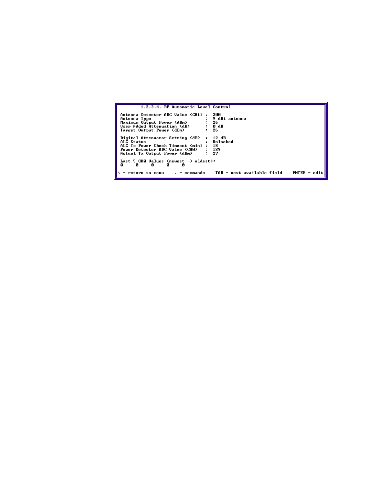
5. Configure IP Address.
a. Go to screen 1.5.1.2 IP Port Configuration.
b. Configure IP address and IP Mask for Port 2 given by the network
administrator.
c. Type “.n” to change to Port 3.
24
SkyWay Series Multi-Point Operator’s Guide
d. Configure IP address and IP Mask for Port 3 given by the network
administrator.
e. Type “.w” and press Enter to update database.
6. Cycle the Port (or restart the RunTime application).
a. Go to screen 2.2.1 Generic Port Status and Control.
b. Type “.n” and press Enter twice to change to the RF port.
c. Change the administrative status to Cycle Port.
d. Type “.w” and press Enter to cycle the port as shown in the following:
If cycling the port does not update the status, try restarting the RunTime
application by typing “.5” select RunTime, and type “.w” - this will restart the
unit.
25
Chapter 2: Configuring Your SkyWay Series Unit(s)
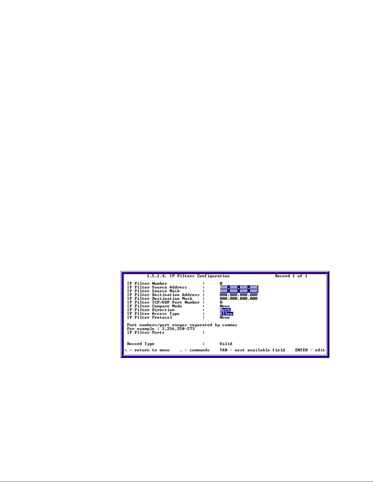
Configuring ALC/ADFC
The purpose of ALC is to periodically adjust the output power to the target output
power if it has changed due to environmental or configuration changes
(temperature, antenna, user added attenuation.) to ensure that the unit output
power complies with the rules and mandates of the FCC, and other regulatory
bodies.
The fields and settings are:
Antenna Detector ADC Value. This is a reading of the chip code for Solectek
antennas.
Antenna Type. This is the antenna type based on the channel 1 value.
Maximum Output Power. This is the maximum output power this unit can
transmit, for the type of antenna it is connected to, under the current country's
laws.
User Added Attenuation. 0-31 dB (Read/Write). This is the amount of extra
attenuation the user has specified to decrease the transmit output power
Target Output Power. This is the power in which the ALC will automatically
adjust to. This target is equal to the maximum output power subtracted by the user
added attenuation.
Digital Attenuator Setting. This is the current amount of dB that the digital
attenuator is adding to the transmit output power signal. Less dB means a higher
output power signal is being sent, more dB means a lower output power is being
sent.
ALC Status. OFF, Unlocked, Locked, and Locked checking. Off indicates the
port is down and ALC will do nothing. Unlocked indicates that the system is
currently adjusting the power to meet the target. Locked indicates that the actual
output power and the target output power are equal, and the power is stable.
Locked checking indicates that the timer has expired, and although it is currently
locked, the ALC will check to ensure that the output power has not changed.
ALC Tx Power Check Timeout. 1 to 30,000 seconds; defaulted to 1800
seconds (30 mins) (Read-Write). This is the timeout value in seconds that the ALC
will check its transmit output power.
26
Power Detector ADC Value. This is the ADC value read from channel 0 which
is the transmit output power level.

Actual Transmit Power. This is the actual output power level (dBm) that
SkyWay is transmitting at. This value is converted from the swALCADCCH0
value.
SkyMate Specific Fields:
CR31 Manual Tx Power Setting. This is the BBP register that actually controls
the output power. It will vary from 0-254 by even numbers. The value of highest
power is 128 and increments up to 254, wraps to zero and increments to the lowest
power at 126.
Power Detector ADC Value. For the SkyMate this value is coming out of the
BBP register 58.
Advanced Configuration
Dynamic Routing
Dynamic Routing Protocols use dynamic routing algorithms to exchange the
routing and link information, from which the best paths to reach destinations are
calculated. The SkyWay-Net and SkyMate bridge/routers use distance vector
routing dynamic routing protocol.
SkyWay Series Multi-Point Operator’s Guide
The distance vector routing protocol maintains and exchanges with other neighbor
routers a distance vector table that consists of a series of destinations (vectors) and
costs (distances) to reach them. The cost of the directly connected networks is
normally fixed at 1, reflecting a single hop, but also can reflect some other
measurement taken for the link such as the traffic, speed, etc. The cost of nondirectly connected network is calculated by adding the cost reported to it in a
neighbor's distance vector table to the cost of the link to that neighbor.
This section focuses on Routing Information Protocol (RIP). These include:
• RIP Protocol
• IGMP Protocol
RIP Protocol
RIP protocol uses a distance vector algorithm and has three versions: RIP, V1compatible, and RIP 2. The following sections are applicable for all versions of
RIP.
RIP Protocol Configuration
The RIP Protocol Configuration screen has eight settings:
27

Chapter 2: Configuring Your SkyWay Series Unit(s)
• RIP
• Propagate Static Routes
• Propagate Local Routes
• Triggered Update
• Poisoned Reverse
• Regular Update Interval
• Route Expire Age
• Route Holddown Age
The following sections describe each setting and their functions.
Use this screen to display and configure the RIP protocol. When the RIP protocol
is enabled, the SkyWay-Net routers will learn and propagate routes to their
neighbors.
The following sections describe each field, settings and their functions:
RIP. Enabled or Disabled. Enables or disables the RIP protocol.
Note: The RIP protocol will not run if routing is disabled no matter that RIP is
enabled or disabled.
Propagate Static Routes. Yes or No. Determines if RIP is propagating static
routes.
Propagate Local Routes. Yes or No. Determines if RIP is propagating local
routes.
Note: No matter whether this setting is yes or no, the RIP will not advertise a
local route to its directly connected network.
RIP Triggered Update. Enabled or Disabled. If Triggered Update is enabled,
RIP will send out an update packet when learned routes change. After the update
packet is sent a timer will be started. The expiration time of the timer is set
randomly to 1-5 sec. If there is another triggered update coming during this period,
it will not be sent out until the timer expires.
RIP Poisoned Reverse. Enabled or Disabled. If Reverse Poison is enabled, RIP
will send all route information learned from this port, with the metric set to
infinity(16). This happens when the RIP routing table is being broadcasted, in
order to eliminate loops.
28
Regular Update Interval. 5 - 180 seconds. The interval (seconds) between RIP
sending out two regular updates.

SkyWay Series Multi-Point Operator’s Guide
Route Expire Age. 10 - 300 seconds. If the route has not been refreshed or
changed during this period of time (seconds), the route expires. When the route
expires the metric is changed to infinity(16).
Route Holddown Age. 0 - 300 seconds. The period of time in seconds after a
route has expired before it is deleted.
RIP Port Configuration
RIP port configuration defines the RIP running policy on different physical ports.
Port IP Address. The IP address of the physical port on which a RIP running
policy is defined. It selects automatically by RIP and user can not change it.
Auth Type. No Authentication, Simple Password or MD5. The type of
authorization used on this interface. RIP Authorization only supported by RIP II.
If it's enabled, the RIP route will only accept routes with the same authorization
key as that of itself.
Note: The MD5 is not fully supported on current software version.
Authorization Key. Max length is 16, letter or digit. The value to be used as the
Authorization Key whenever the corresponding Authorization type has a value
other than No Authentication. A modification of the corresponding Authorization
type does not modify the authorization key value. The Authorization key.
Send Mode. doNotSend, RIP1 (implies sending IP updates compliant with RFC
1058), V1-Compatible (implies broadcasting RIP2 updates using RFC 1058 route
subsumption rules) or RIP2 (Implies multicasting RIP2 updates). Indicates what
the router sends on this interface. The border RIP1 router will not send out internal
subnets information.
Receive Mode . RIP1, RIP2, RIP1orRIP2 or doNot Receive. This indicates
which versions of RIP updates are to be accepted. Note that RIP2 and RIP1orRIP2
implies reception of multicast packets.
Metric. The default RIP route cost of the physical connected network.
Configuring for RIP
Ensure the IP routing is enabled before configure the RIP. If not, see “Configuring
for Routing Only” on page20.
After IP routing is enabled, a default RIP port configuration record will be added
for each physical port.
29

Chapter 2: Configuring Your SkyWay Series Unit(s)
1. Enable RIP protocol.
a. Go to screen 1.5.5.1 change the RIP from disable to enable.
b. Type “.w” to save the change.
2. Configuring for RIP Port.
a. Go to screen 1.5.5.2 RIP Port Configuration
b. Configure RIP send mode.
c. Configure RIP receive mode.
d. Configure RIP Authorization Type and password (if required).
e. Type “.w” to save the change.
f. Type “.n” to configure next RIP port.
IGMP
IGMP (Internet Group Management Protocol) can be configured on a per port
basis. To access this screen, type “.152” and press Enter.
30
This screen configures the general parameters of IGMP ports.
Port Number. The physical port for which the configuration applies.
IGMP Querier. Enables or Disables IGMP querying.
Version. The IGMP version used.

Robustness Variable. The IGMP Robustness Variable.
Query Interval. The time, in seconds, between sending of IGMP General
Queries.
Query Response Interval. The time, in seconds, used for the Max Response
Time variable that inserted into IGMP General Queries.
Last Member Query Interval. The time, in seconds, used for the Max Response
Time variable that inserted into IGMP Group-Specific Queries and the time
between sending of IGMP Group-Specific Queries.
Startup Query Interval. The time, in seconds, between sending of IGMP
General Queries upon startup.
Unsolicited Report Interval. The time, in seconds, between repetitions of a
host's initial report of membership in a group.
Startup Query Count. The number of IGMP General Queries sent upon startup.
Last Member Query Count. The number of IGMP Group-Specific Queries sent
before router assumes that there are no local members.
Network Management
SkyWay Series Multi-Point Operator’s Guide
This part of the chapter focuses on methodology to maximize your wireless
network. The sections includes:
• Filters
• Remote RF Configuration
• Bandwidth Management
• SNMP
• SNTP
• BootP/DHCP Server-Client Protocols)
Filters
There are to types of filters you can use on your SkyWay Series units: Bridge and
IP Address.
Bridge Filters
There are several options for creating and using of Bridge Filters. These include:
• Creating Source Filter
• Creating Destination Filter
• Creating Source and Destination Filter
• Creating Filters SNAP, Ethernet, LSAP Frames
• Creating Filter Bridge Ports
The following sections describe how to create and use these filters.
31

Chapter 2: Configuring Your SkyWay Series Unit(s)
Creating Source Filter
1. Add MAC address of the Source in which you would like to Filter.
2. Add the Source Mask of the Source IP address.
3. Set the Access Direction to Input, Output, or Both. This will filter out traffic
coming in, going out, or both in and out of the Filter.
4. Set the Filter Access to Allow or Deny. Allow or Deny traffic going through
the filter from the Source IP address.
Creating Destination Filter
1. Add MAC address of the Destination in which you would like to Filter.
2. Add the Destination Mask.
3. Set the Access Direction to Input, Output, or Both. This will filter out traffic
coming in, going out, or both in and out of the Filter.
32
4. Set the Filter Access to Allow or Deny. Allow or Deny traffic going through
the filter from the Destination MAC address.
5. Type “.w” to save the changes.

SkyWay Series Multi-Point Operator’s Guide
Creating Source and Destination Filter
1. Add MAC addresses of the Source and Destination in which you would like to
Filter.
2. Add the Source and Destination Masks of the Source and Destination IP
address.
3. Set the Access Direction to Input, Output, or Both. This will filter out traffic
coming in, going out, or both in and out of the Filter.
4. Set the Filter Access to Allow or Deny. Allow or Deny traffic going through
the filter from the Destination MAC address.
5. Type “.w” to save the changes.
Creating Filters SNAP, Ethernet, LSAP Frames
These filters will allow the user to filter out frames with SNAP, Ethernet, and
LSAP type of headers.
1. Create SNAP, Ethernet and LSAP frames in the 802.3 formats.
2. SNAP Data Type: Enter SNAP for the Data type.
3. The Data Value should be the Protocol Identification of the IPX SNAP header.
4. Ethernet Data Type: Enter Ethernet for the Data type.
5. Enter the Frame type of the IPX Ethernet header for the Data Value.
6. LSAP Data Type: Enter LSAP data type.
7. Enter the DSAP and SSAP bytes for the Data Value.
8. All Data Values should be in hexadecimal format
9. Set the Data Mask. To deny the entire Frame, set the Data Mask to FFFF.
10. Set the Filter Direction Input, Output, or Both.
11. Set the Filter to access Allow or Deny.
Note: Source and Destination features can be used in accordance with this
feature.
33
Chapter 2: Configuring Your SkyWay Series Unit(s)
12. Type “ .w” to save the changes.
Creating Filter Bridge Ports
1. The use of the IP Port mode can be done in conjunction with the Source and
Destination Field on the Bridge Screen.
2. Set the Access Direction to Input, Output, or Both.
3. Set the Bridge Port to for example 2, 256, 256-273.
4. Set the Access to Allow* or Deny.
Note: * Allow filters have priority over Deny filters.
5. Type “.w” to save the changes.
IP Filters
There are several options for creating IP Filters. These include:
• Creating Source Filter
• Creating Destination Filter
• Creating Source and Destination Filter
• Creating Filters For UDP/TCP Compare Mode
• Creating Filters For Protocols ICMP, TCP, And UDP
• Creating Filter IP Ports
The following section describe how to create and use these filters.
Creating Source Filter
1. Add IP address of the Source in which you would like to Filter.
2. Add the Source Mask.
34
3. Set the Access Direction to Input, Output, or Both. This will filter out traffic
going in, out, or both in and out of the Filter.
4. Set the Filter Access to Allow or Deny. Allow or Deny traffic going through
the filter from the Source IP address.

SkyWay Series Multi-Point Operator’s Guide
5. Type “.w” to save the changes.
Creating Destination Filter
1. Add IP address of the Destination in which you would like to Filter.
2. Add the Destination Mask of the Destination IP address.
3. Set the Access Direction to Input, Output, or Both. This will filter out traffic
coming in, going out, or both in and out of the Filter.
4. Set the Filter Access to Allow or Deny. Allow or Deny traffic going through
the filter.
5. Type “.w” to save the changes.
Creating Source and Destination Filter
1. Add IP addresses of the Source and Destination in which you would like to
Filter
2. Add the Source and Destination Masks.
3. Set the Access Direction to Input, Output, or Both. This will filter out traffic
going in, out, or both in and out of the Filter.
4. Set the Filter Access to Allow or Deny. Allow or Deny traffic going through
the filter from the Destination IP address.
5. Type “.w” to save the changes.
Creating Filters For UDP/TCP Compare Mode
1. The use of the Compare Mode can be done in conjunction with the Source and
Destination Fields on the IP Filter Screen.
2. Set the UDP/TCP Port to a corresponding UDP/TCP Port number.
3. Set the Compare Mode to Filter the traffic Greater Than, Less Than, Equal, or
Not Equal to the Port number specified above.
4. Set the Access Direction to Input, Output, or Both.
5. Set the Access to Allow, or Deny.
6. Type “.w” to save the changes.
Creating Filters For Protocols ICMP, TCP, And UDP
1. The use of the Protocol mode can be done in conjunction with the Source and
Destination Fields on the IP Filter Screen.
2. Set the Access Direction to Input, Output, or Both.
3. Set the IP Protocol to ICMP, TCP, or UDP.
4. Set the Access to Allow or Deny.
5. Type “.w” to save the changes.
35
Chapter 2: Configuring Your SkyWay Series Unit(s)
Creating Filter IP Ports
1. The use of the IP Port mode can be done in conjunction with the Source and
Destination Field on the IP Filter Screen.
2. Set the Access Direction to Input, Output, or Both.
3. Set the IP Port to for example 2, 256, 256-273.
4. Set the Access to Allow or Deny.
5. Type “.w” to save the changes.
Remote RF Configuration
Remote RF Configuration can be used to remotely configure each field on the RF
Transceiver (RF frequency, scrambler tap, modulation) of all SkyWay or SkyMate
sub stations. This feature can only be used to configure all sub stations on the
network at one time. It is not possible to remotely configure one sub at a time.
Using Remote RF Configuration
1. On the Base, go to the Remote RF Configuration (3.4) screen
2. Change the Remote Timeout, RF Channel, Data Rate, and Scrambler Tap field
to the desired value, then press enter
3. Change the Action field to “Request remote RF configuration”
4. Type “.w” and then type “.r”
5. Check the Status field and make sure that it says Ready.
6. If the Status is “Not Ready”, you will need to troubleshoot your link to make
sure that the Base is able to communicate to each of the Subs.
7. Check the Error field and make sure that there are no errors.
8. If you receive an error in the Error field, you will need to troubleshoot your
link according to the error that was received.
9. If the Status is “Ready” and there are no errors, change the Action field to
“Confirm remote RF configuration”
10. Type “.w” and wait 1 second.
11. Type “.r”
36

SkyWay Series Multi-Point Operator’s Guide
The RF Channel, Data Rate, and Scrambler Tap should have changed to the
desired values.
Confirming RF Changes on the Base
1. Go to the RF Transceiver Configuration screen.
2. Check to see that the RF Frequency, RF Data Rate, and Scrambler Tap values
have changed to the desired values that were set using Remote RF
Configuration.
3. If everything is correct, go to the RF Port Status (2.2.4.1) screen.
4. Check to see that the RF Data Rate and RF Channel values have changed to
the desired values that were set using Remote RF Configuration.
5. If everything is correct, go to the WCOPP Sub Port Status (2.6.2) screen.
6. Check to see that the Subs are in NRM status and that RRs are being both
transmitted and received.
If everything is correct, remote RF configuration has been successful.
Confirming RF changes on the SkyWay Subs
1. Go to the RF Transceiver Configuration (1.2.3.3) screen.
2. Check to see that the RF Frequency, RF Data Rate, and Scrambler Tap values
have changed to the desired values that were set using Remote RF
Configuration.
3. If everything is correct, go to the RF Port Status (2.2.4.1) screen.
4. Check to see that the RF Data Rate and RF Channel values have changed to
the desired values that were set using Remote RF Configuration.
5. If everything is correct, go to the WCOPP Sub Port Status (2.6.2) screen.
6. Check to see that the Sub is in NRM status and that RRs are being both
transmitted and received.
If everything is correct, remote RF configuration has been successful.
Confirming RF changes on the SkyMate Subs
1. Go to the RF Transceiver Configuration (1.2.3.3) screen.
37

Chapter 2: Configuring Your SkyWay Series Unit(s)
2. Check to see that the RF Frequency, RF Data Rate, and Scrambler Tap values
have changed to the desired values that were set using Remote RF
Configuration.
3. If everything is correct, go to the RF Port Status (2.2.4.1) screen.
4. Check to see that the RF Data Rate and RF Channel values have changed to
the desired values that were set using Remote RF Configuration.
5. If everything is correct, go to the WCOPP Sub Port Status (2.6.1) screen.
6. Check to see that the Sub is in NRM status and that RRs are being both
transmitted and received.
If everything is correct, remote RF configuration has been successful.
Bandwidth Management
WCOPP-AP Bandwidth Management allows you to define the bandwidth
allocated for a particular logical link. This logical link consists of the RF link
between one base station and one associated sub station. All bandwidth
management configurations are entered on the base station. This bandwidth
information will then be conveyed to the sub-stations through XID packets. This
exchange could take several minutes to complete since the base must acknowledge
that the sub has truly received the XID packet. The three different modes of
bandwidth allocation are mutually exclusive.
There are two choices for the Bandwidth Management setting:
• No Bandwidth Limitations
• Limited Bandwidth
No Bandwidth Limitations. This is the default scheme that has currently been
running over WCOPP. Bandwidth is not measured and is divided evenly by the
nature of the polling protocol. Each logical link is serviced in a round-robin
fashion and the full capacity of the line is given to that logical link while it is being
serviced. The line will be relinquished when the data queued has been sent.
Limited Bandwidth. This mode allows the user to limit the bandwidth of a
logical link to up to 11Mb/s in 64Kb/s allocation blocks. This bandwidth
allocation will place a ceiling on the bandwidth allowed on the logical link. The
total bandwidth available is the physical bandwidth of the base RF port. When
limiting the bandwidth every station need not be limited. Logical links can be
assigned to have a limited bandwidth of no max, meaning they will implement no
control over their bandwidth. The sum of the logical link allocations can be greater
than the total available physical bandwidth, thus putting the system in an overallocated state. This can be done because in a real life network scenario each sub
will not be using the max bandwidth available to it.
38

SkyWay Series Multi-Point Operator’s Guide
The limited management scheme limits the bandwidth by measuring the total
throughput of a station; this entails measuring both the I-frames received and the Iframes sent. The scheme runs with one-second cumulative windows, which are
leveled out over 5 second blocks. Starvation is avoided by using RNR's to throttle
the bandwidth of the hogging side.
Bandwidth management can be used to configure the amount of bandwidth that
each Sub station will be limited to. The bandwidth can only be configured using
the Base. All Subs can be configured at once or each Sub can be configured
individually.
Configuring Bandwidth Management
Base
1. Go to the RF Bandwidth Management Configuration (1.2.3.5) screen
2. Change the Bandwidth Management Mode to “Limited”
Subs - All Set Simultaneously
1. Change the Default Bandwidth value to a desired amount
2. Change the Set all Subs to Default field to “Yes”
3. Type “.w”
Subs - Each Set Individually
1. Go to the Station Bandwidth and change each value as desired.
2. Type “.w”
Verifying Bandwidth Management Changes
Base
1. On the Base unit, go to the RF Bandwidth Management Configuration
(1.2.3.5) screen and verify all Subs have changed to the desired amount.
2. Go to the RF BW Management Status (2.2.4.1) screen, verify Bandwidth
Mode is “Limited” and each Sub has the correct configured amount.
39

Chapter 2: Configuring Your SkyWay Series Unit(s)
Sub(s)
3. On the sub unit, go to the RF BW Management Status (2.2.4.1) screen, verify
Bandwidth Mode is “Limited” and the Sub has the correct configured amount.
SNMP
Setting Network Management Security Parameters
Use the Network Management Security Configuration screen to set up security
parameters for network management. To access his screen, you must have an
access level of Super.
Note: This screen is not accessible via SNMP.
This screen allows a user of Super User status to configure the SNMP Community
Names and management tool addresses.
Read Community Name. The read-only community name of the SkyWay agent.
Must match the read community name configured on the Network Management
Station (NMS) to be able to perform get and/or get-next requests from the NMS.
Write Community Name. The read-write community name of the SkyWay
agent. Must match the write community name configured on the NMS in order to
perform set requests from the NMS to the Skyway.
Trap Community Name. The trap community name of the SkyWay agent. If
you set Enable Traps to Yes and the NMS expects SNMP traps with community
name, this field must match community name configured on the NMS.
Enable Traps. Set to Yes to enable SkyWay to log and transmit SNMP traps. Set
a Trap Destination Address to send traps to the NMS.
Authentication Traps. Set to Yes to cause a trap when an SNMP packet is
received with an incorrect community name.
NMS IP Address 1. The IP address of the first NMS. This address setting is
optional when using a NMS. This provides an extra layer of security by forcing the
IP addresses to match.
NMS IP Address 2. The IP address of the second Network Management station.
This address setting is optional when using a NMS. This provides an extra layer of
security by forcing the IP addresses to match.
40
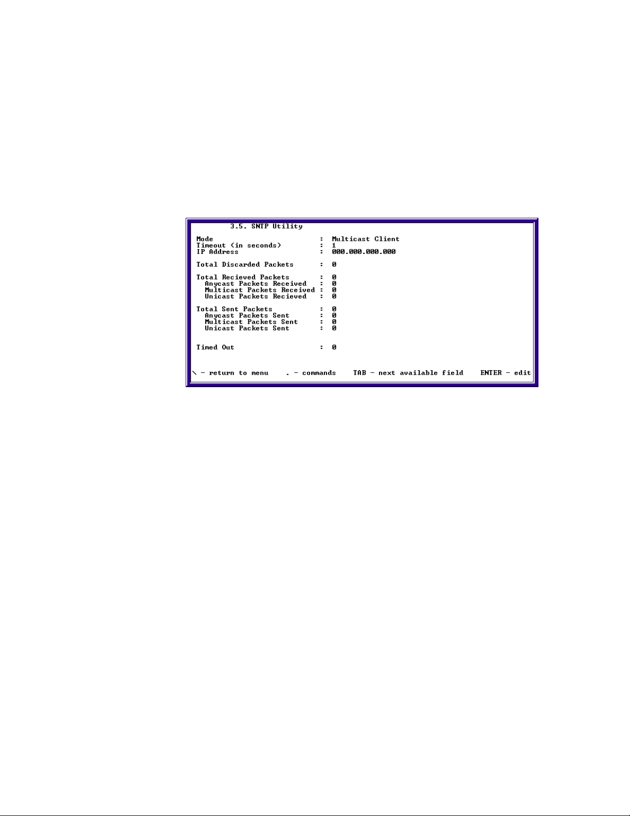
SkyWay Series Multi-Point Operator’s Guide
Trap Destination IP Address 1. The IP address of the first NMS to receive
SkyWay SNMP traps. Enable Traps must be set to Yes.
Trap Destination IP Address 2. The IP address of the second NMS to receive
SkyWay SNMP traps. Enable Traps must be set to Yes.
SNTP
SNTP (Simple Network Time Protocol) is a utility/application used to synchronize
clocks on subs or clients with bases or servers. It is assigned screen 3.5 on
SkyWay Net and 3.4 on SkyMate.
The SNTP screen 3.5/3.4 has three setting:
• Mode
• Timeout
• IP Address
The following section describes each setting and their functions.
Mode. Choose a value between following modes:
• Not installed
• Disable
• Anycast server
• Multicast server
• Unitcast server
• Anycast Multicast server
• Anycast Unicast server
• Multicast Unicast server
• Anycast Multicast Unicast server
• Anycast client
• Multicast client
• Unicast client
41

Chapter 2: Configuring Your SkyWay Series Unit(s)
This field lets a user choose if the unit will be a client or a server or have this
utility disabled on that unit.
Timeout. 1-14400 seconds. The interval of time in seconds a periodic timeout
value.
IP Address. 000.000.000.000. Enter the IP address of the server where a request
for a time stamp is sent.
SNTP Configuration
Use 3.5/3.4 SNTP utility screen for setting values for fields.
1. Check and document the time and date of the unit on screen 1.1.4 System
Clock Configuration.
2. Select a mode based on three criteria described below from different values.
Default mode is Multicast client.
3. Set a timeout value if mode is Anycast client, Unicast client, Multicast server
or any combination of Multicast server.
4. Set IP address of a SNTP server if mode is set to Unicast client.
5. Type “.w” to write changes.
6. Check to verify the time and date of the client unit on screen 1.1.4 System
Clock Configuration has synchronized.
Changing SNTP Modes
Anycast Mode
1. On the Server:
• Change mode to either Anycast server or any combination of Anycast
server.
• Type “.w” to write changes.
2. On the Client:
• Change the mode to Anycast client.
• Set a timeout value to receive a packet.
• Type “.w” to write changes.
Multicast Mode
1. On the Server:
• Change mode to either Multicast server or any combination of Multicast
server.
42
• Set a timeout value to send a periodic multicast SNTP packet after initial
write.
• Type “.w” to write changes.
2. On the Client:

SkyWay Series Multi-Point Operator’s Guide
• Change the mode to Multicast client.
• Type “.w” to write changes.
C.Unicast Mode
1. On the Server:
• Change mode to either Unicast server or any combination of Unicast
server.
• Type “.w” to write changes.
2. On the Client:
• Change to mode to Unicast client.
• Set a timeout value to receive a packet.
• Type “.w” to write changes.
BootP/DHCP Server-Client Protocols
Configuring BootP/DHCP on SkyWay-Net
The BOOTP (BOOTstrap Protocol) Relay Agent, DHCP (Dynamic Host
Configuration Protocol) Server, and DHCP Client can be configured using the
following four screens:
• 1.5.4.1 BOOTP Protocol Configuration
• 1.5.4.2 DHCP Client Configuration
• 1.5.4.3 DHCP Server Protocol Configuration
a. 1.5.4.3.1 DHCP Server Protocol Configuration
b. 1.5.4.3.2 DHCP Address Pool Configuration
c. 1.5.4.3.3 DHCP Manual Configuration
BOOTP Protocol Configuration
This screen configures the general parameters of the BOOTP Relay Agent, the
DHCP Server, and the DHCP Client.
Relaying. Enables or Disables the BOOTP Relay Agent.
Destination Address. The IP address that the BOOTP Relay Agent forwards
BOOTP Requests to.
Maximum Hops. The maximum number of BOOTP hops that a BOOTP Request
may have before being discarded by the BOOTP Relay Agent.
43

Chapter 2: Configuring Your SkyWay Series Unit(s)
Broadcast Reply. Determines whether the BOOTP Relay Agent will forward
BOOTP Replies with the broadcast bit set.
DHCP Client Configuration
DHCP Client. Enables and disables the DHCP client. When enabled, IP port 3
can only be configured via DHCP.
DHCP Client DB Version. The DHCP client database version number. When a
new DHCP client database is being created, this field must be changed to a
number greater than the DHCP client's DHCP Client DB Header Tag, which is 0
by default.
DHCP Client DB Header Tag. The current DHCP client database version
number. When the DHCP client is contacting the next server to use in its bootstrap
process, it will compare its current DHCP Client DB Header Tag to the DHCP
Client DB Header Tag of the database located on the next server in its bootstrap
process. If the tag of the database located on the next server in its bootstrap
process is greater than the DHCP client's current tag, the database will be
downloaded and the DHCP client's tag will be changed to the downloaded
database's tag; otherwise, the database will not be downloaded.
DHCP Server Configuration
This section has three screens to configure the DHCP Server. These are:
• 1.5.4.3.1 DHCP Server Protocol Configuration
• 1.5.4.3.2 DHCP Address Pool Configuration
• 1.5.4.3.3 DHCP Manual Configuration
The following screens and descriptions define the fields and settings.
DHCP Server Protocol Configuration
DHCP Server. Enables or Disables the DHCP Server.
TFTP Remote DB Agent. Enables or Disables the TFTP Remote Database
Agent. This feature allows the DHCP server's database of current bindings to be
stored offline on a TFTP server. Upon a reboot, the DHCP server downloads and
restores its saved database of current bindings.
44

SkyWay Series Multi-Point Operator’s Guide
TFTP Remote DB Agent IP. The IP address of the TFTP Remote Database
Agent.
DB File Name. The name of the database file to be saved to and read from the
Remote DB Agent.
DB Agent Write Delay. The time, in seconds, between writes to the Remote DB
Agent.
Number of ICMP Requests. The number of times that the DHCP server should
probe an IP address before offering it to a DHCP client.
ICMP Request Timeout. The time, in seconds, that the DHCP server will wait to
receive a reply to its probe.
Check Network. Enables or disables a process of insuring that a DHCP client is
assigned an address consistent with the subnet it is attached.
DHCP Address Pool Configuration
The DHCP server will search address pools that have been configured on this
screen when choosing a configuration to assign to a DHCP client if a manual
configuration was not found for the client. When creating a pool, only the First IP
Address, Last IP Address, Subnet Mask, and Lease Duration are required.
First IP Address. The first available IP address of the pool.
Last IP Address. The last available IP address of the pool.
Subnet Mask. The subnet mask of the pool.
Default Router. The default gateway of the pool.
Lease Duration (DD, HH, MM). The length of the lease in days, hours, and
minutes for the pool. A lease of 0 days, 0 hours, and 0 minutes is an infinite lease.
DNS Server 1. The first DNS server of the pool.
DNS Server 2. The second DNS server of the pool.
NetBIOS WINS IP Address. The IP address of the NetBIOS name server for the
pool.
NetBIOS Node Type. The NetBIOS node type for the pool. The following are
acceptable entries: “p”=peer-to-peer, “b”=broadcast, “m”=mixed, “h”=hybrid.
Domain Name. The domain name for the pool.
45

Chapter 2: Configuring Your SkyWay Series Unit(s)
TFTP Server. The IP address of the next server to use in bootstrap for the pool.
This is the server that the SkyMate or SkyWay Net Substation will download its
configuration database from.
Row Status. The status of the pool. When first adding the pool, “Create and go”
should be used; the state will then be changed to active. If the pool is to be deleted,
then the status should be changed to “Destroy.”
DHCP Manual Configuration
The DHCP server will search manual configurations that have been configured on
this screen when choosing a configuration to assign to a DHCP client. A manual
configuration is a binding of a configuration to a hardware type and hardware
address or a client identifier. When creating a manual configuration, only the First
IP Address, Last IP Address, Subnet Mask, Lease Duration, and Client ID or
Hardware Type and Hardware Address are required.
IP Address. The IP address of the configuration.
Subnet Mask. The subnet mask of the configuration.
Hardware Type. The physical network type that the client is using, e.g.
“1”=Ethernet or RF. For a complete list, refer to the ARP section of the “Assigned
Numbers” RFC.
Hardware Address. The MAC address or hardware address of the client in
hexadecimal.
Client ID. The client identifier used by the client. Typically, this is the hardware
type followed by the Hardware Address. For example, a Solectek product or
Windows operating system with a hardware type of 1 and hardware address of
0x00-01-02-03-04-05 would use a client identifier of 01-00-01-02-03-04-05.
Default Router. The default gateway of the configuration.
Lease Duration (Days, Hours, Minutes). The length of the lease in days,
hours, and minutes for the configuration. A lease of 0 days, 0 hours, and 0 minutes
is an infinite lease.
46
DNS Server 1. The first DNS server of the configuration.
DNS Server 2. The second DNS server of the configuration.

SkyWay Series Multi-Point Operator’s Guide
NetBIOS WINS IP Address. The IP address of the NetBIOS name server for the
configuration.
NetBIOS Node Type. The NetBIOS node type for the configuration. The
following are acceptable entries: “p”=peer-to-peer, “b”=broadcast, “m”=mixed,
“h”=hybrid.
Domain Name. The domain name for the configuration.
TFTP Server. The IP address of the next server to use in bootstrap for the
configuration. This is the server that the SkyMate or SkyWay Net Substation will
download its configuration database from.
Database File Name. The file name of the configuration file to download from
the next server to use in bootstrap for the configuration.
Row Status. The status of the configuration. When first adding the configuration,
“Create and go” should be used; the state will then be changed to active. If the
configuration is to be deleted, then the status should be changed to “Destroy.”
Configuring BootP and DHCP on SkyMate
The BOOTP (BOOTstrap Protocol) Relay Agent and DHCP Client (Dynamic
Host Configuration Protocol) can be configured using the following two screens:
1.5.4.1 BOOTP/DHCP Protocol Configuration
1.5.4.2 DHCP Client Protocol Configuration
BOOTP/DHCP Protocol Configuration
SkyMate Example Screen
This screen configures the general parameters of the BOOTP Relay Agent and the
DHCP Client.
Relaying: Enables or Disables the BOOTP Relay Agent.
Destination Address: The IP address that the BOOTP Relay Agent forwards
the BOOTP Requests.
Maximum Hops: The maximum number of BOOTP hops that a BOOTP Request
may have before being discarded by the BOOTP Relay Agent.
Broadcast Reply: Determines whether the BOOTP Relay Agent will forward
BOOTP Replies with the broadcast bit set.
DHCP Client: Enables and disables the DHCP client. When enabled, IP port 3
can only be configured via DHCP.
47

Chapter 2: Configuring Your SkyWay Series Unit(s)
DHCP Client Protocol Configuration
SkyMate Example Screen
This screen can be used to configure the DHCP client.
DHCP Client DB Version: The DHCP client database version number. When a
new DHCP client database is being created, this field must be changed to a
number greater than the DHCP client's DHCP Client DB Header Tag, which is 0
by default.
DHCP Client DB Header Tag: The current DHCP client database version
number. When the DHCP client is contacting the next server to use in its bootstrap
process, it will compare its current DHCP Client DB Header Tag to the DHCP
Client DB Header Tag of the database located on the next server in its bootstrap
process. If the tag of the database located on the next server in its bootstrap
process is greater than the DHCP client's current tag, the database will be
downloaded and the DHCP client's tag will be changed to the downloaded
database's tag; otherwise, the database will not be downloaded.
File Transfer Utilities
There are three types of file transfer utilities:
• TFTP
• X Modem
• Y Modem
The following sections describe these utilities and procedures to use them.
TFTP
Trivial File Transfer Protocol (TFTP) transfers files via the Ethernet connection.
There are two TFTP screens:
• TFTP Server Configuration
• TFTP File Transfer
48

SkyWay Series Multi-Point Operator’s Guide
TFTP Server Configuration
The TFTP Server Configuration screen the following settings:
Server Status. Enabled, Send only, or Disabled. Set as Enabled or Send only to
configure as a TFTP server. The Send only setting allows files to be sent and
cannot receive files.
Timeout. 20. The amount of time in seconds the TFTP Server will wait before a
timeout occurs. For example, if the server sends a packet and it is not
acknowledged by the client before the timeout expires, the server shuts down the
connection.
Current State. Receiving, Sending, Idle.
Current File. The type of file currently being transferred. See Table1: File
Names on page50 for a list of file names and their descriptions.
Read Requests. Number of read requests received by the TFTP Server.
Write Requests. Number of write requests received by the TFTP Server.
Aborted Sessions. Number of times an upload was aborted since the last reboot.
The TFTP File Transfer screen has the following settings:
IP Host Address. 000.000.000.000. This is the IP Address of the PC that is
running the server.
File Type. The type of file to be transferred. See Table1: File Names on page50
for a list of file names and their descriptions.
File Name. The name of the file to be transferred. See Table1: File Names on
page50 for a list of file names and their descriptions.
Timeout. 20. Tells the server what the timeout parameter will be, how long the
server should wait to receive an acknowledgement before retransmit (up to 5
retries) and then terminating the connection.
49
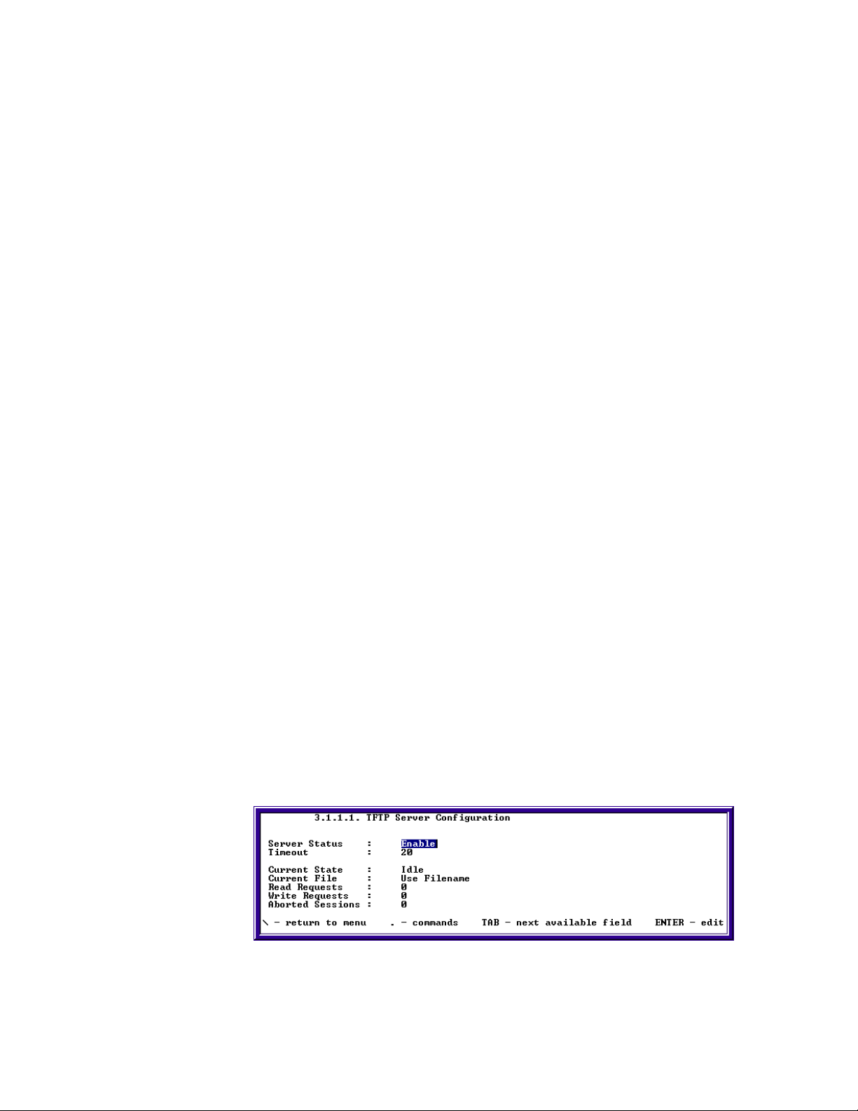
Chapter 2: Configuring Your SkyWay Series Unit(s)
Block Size. Range: 128 to 1400 bytes. The amount of data that is sent over at one
time (128 to 1400 bytes).
Session Type. Receive, Send, Abort. The action to be performed by the client,
i.e., either send a file to the server or receive a file from the server.
Status. Receiving, Transmitting, Failed, Idle, Flashing, Not Installed. The
current status of the transfer.
Bytes Transferred. 0. Counts the number of bytes as the file is currently
transferring and dynamically displays it. If a file isn't currently transferring, this
field displays the number of bytes transferred in the last file transfer.
Number of Retries. 0 (only after an error). The number of retries for the current
of last file transfer.
Error Message. A text message which displays the reason the file transfer failed.
The following table lists the file names to enter as the remote file name in the
TFTP client software on your workstation when transferring files to or from the
Skyway-Net TFTP Server.
Table 1: File Names
File Name Description
BOOTLDR.BIN Boot Loader
FPGA.BIN FPGA
CRSHDUMP.BIN Crash Dump
ERRORLOG.BIN Error Log
BIOS_DB.BIN Bios Database
DATABASE.BIN Run Time Database
DBDEFLT.BIN Default Database
BIOS_APP.BIN Bios Application
RT_APP.BIN Run Time Application
Configuring Skyway as TFTP Server
50
1. Go to screen 3.1.1.1 TFTP Server Configuration

SkyWay Series Multi-Point Operator’s Guide
2. Enable Server Status.
3. Type “.w” to save change.
4. Select “Send Only” mode when you want to deny Server to receive files.
Configuring Skyway as TFTP Client
1. Go to screen 3.1.1.2 TFTP File Transfer.
2. Enter the IP address of the host workstation.
3. Select the File Type to send.
4. Type in the file name (See file definition table above). Bin files have to be in
the format used above.
5. Select Receive (or Send) in the Session Type field.
6. Type “.w” to begin file transfer.
7. Select Abort and type “.w” when halting file transfer already in progress.
Note: TFTP Server software must be running on the PC and configured to send
(or receive) files. On both PCs Server and Client TFTP software the path
must be clearly defined in both applications in order for the file to be
accessed or sent to the intended areas.
Y Modem
51
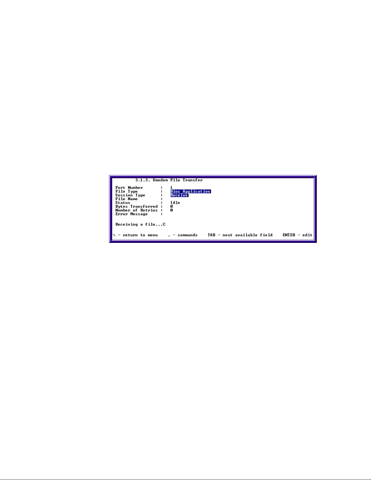
Chapter 2: Configuring Your SkyWay Series Unit(s)
1. Set the File Type to the bin file that you wish to upload or download to the
Skyway or SkyMate Unit.
2. Choose Session type. To download file from Skyway or SkyMate Unit choose
Send.
3. Under “File Name” type in the name in which you want the file to be called.
4. Type “.w” to begin file transfer.
5. Use the Terminal's Application “Receive” mode to receive the file transfer
onto the PC.
6. To Verify that the file is transferring by viewing the “Status” mode as
“Receiving” and the “bytes transferred”.
X Modem
1. Set the File Type to the bin file that you wish to upload or download to the
Skyway or SkyMate Unit.
2. Choose Session type: To download file from Skyway or SkyMate Unit choose
Send.
3. Type “.w” to begin file transfer.
4. Use the Terminal's Application “Receive” mode to receive the file transfer
onto the PC.
5. Verify that the file is transferring by viewing the “bytes transferred” category
on the X Modem screen.
6. To upload file to Skyway or SkyMate Unit choose Receive.
7. Type “.w” to begin file transfer.
52

Chapter 3: Monitoring SkyWay Series Network
This chapter focuses on monitoring your SkyWay Series wireless network. The
following sections describe the screens and their fields. From these fields, you can
determine the status of your RF Link(s) and protocols.
This chapter provides information on:
Monitoring Ports............................................................. 53
Routing............................................................................ 63
Bridging .......................................................................... 67
Management.................................................................... 70
Protocols & Applications................................................ 73
Monitoring Ports
RF Port
There are three sections that focus on RF Ports:
• Connecting the RF Link
• Checking the WCOPP-AP Configuration
• Monitoring Traffic on your RF Link
Connecting the RF Link
After you have configured both your SkyWay-Net Base, SkyWay-Net substations,
and SkyMates, there are several steps that should be taken to ensure that a clean
RF connection has been established. Following these steps will help confirm that
SkyWay-Net and SkyMate configuration has been done correctly.
53
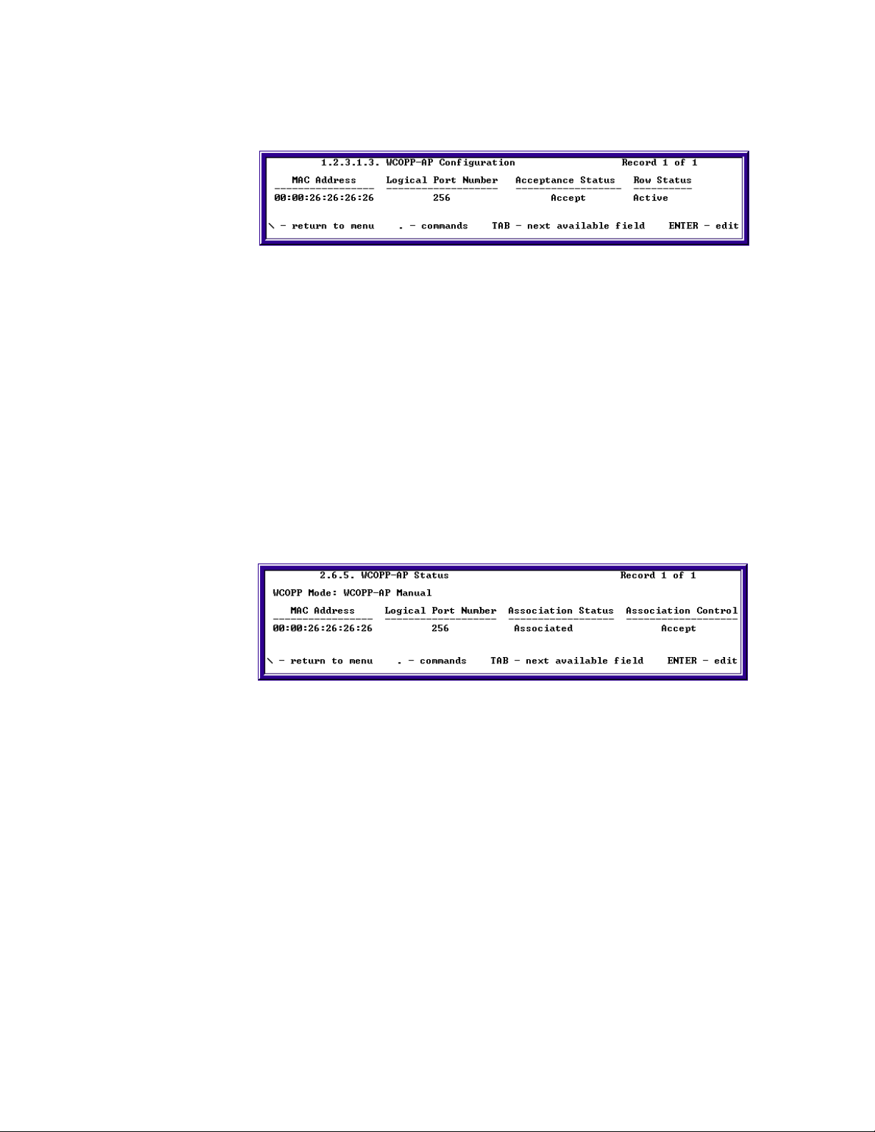
Chapter 3: Monitoring SkyWay Series Network
Checking the WCOPP-AP Configuration
1. On the Base, type “.12313” to go to the WCOPP-AP Configuration screen.
2. Check to see that the correct MAC address is associated with the correct
logical port number.
3. Also check to see that the Association Status is “Accept” and the Row Status
is Active.
4. If the MAC address is incorrect, your base may be in Promiscuous Mode and
might have associated with a random Substation without your knowledge.
5. If the Association Status is “Not Associated” the substation may not have
established a link with a base yet. Check your configuration of both the Base
and Substation to make sure that everything is correct.
Checking the WCOPP-AP Status
1. On the base, type “.265” and press Enter to go to the WCOPP-AP Status
screen.
2. Check to see that the correct MAC address is associated with the correct
logical port number.
3. Also check to see that the Association Status and Association Control are both
set to Accepted.
If the MAC address is incorrect, your base may be in Promiscuous Mode and
might have associated with a random sub-station without your knowledge.
If the Association Status is “Not Associated”, the sub-station may not have
established a link with a base yet. Check your configuration of both the base
and sub to make sure that everything is correct.
54
If the Association Control field says “Standby”- you have the choice to either
“Accept” or “Decline” the sub that is trying to associate with the base.
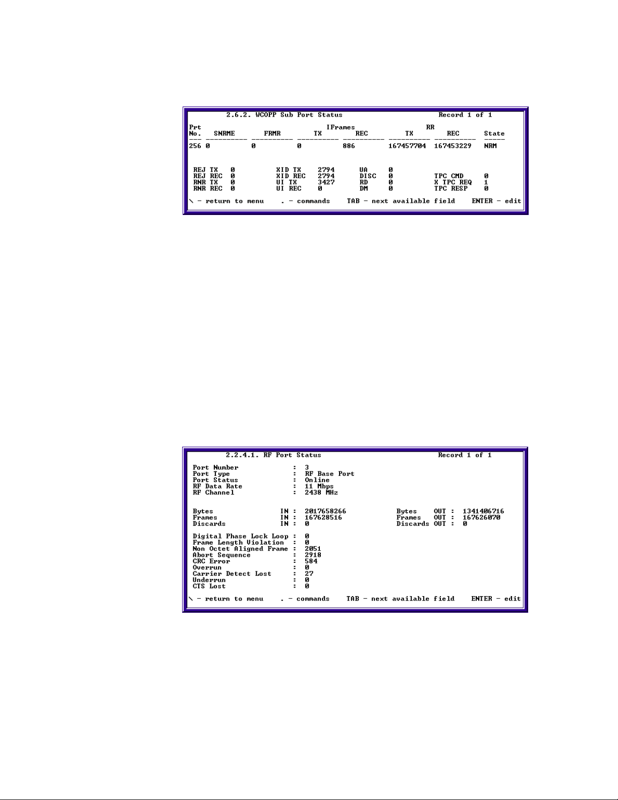
SkyWay Series Multi-Point Operator’s Guide
Checking the WCOPP Sub Port Status
1. On the base, go to the WCOPP Sub Port Status (2.6.2) screen
2. Put the base in monitor mode by typing “.m”
3. Zero out the statistics by typing “.z”
4. Check to see that the Status for the sub is NRM.
5. If any of the following conditions are met, re-check your configuration:
a. Status is NRM-W, NRD, or NDM
b. SNRME counter is incrementing
c. FRMR counter is incrementing
d. The amount of RR TX and RR REC are not similar
Checking the RF Port Status
1. On the base, go to the RF Port Status (2.2.4.1) screen
2. Put the base in monitor mode by typing “.m”
3. Zero out the statistics by typing “.z”
4. Allow to run for 1 minute.
55
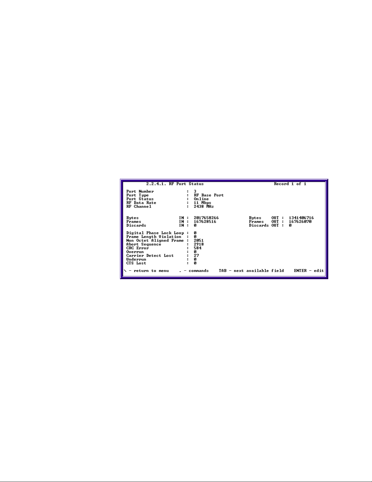
Chapter 3: Monitoring SkyWay Series Network
5. Check to see that the amount of errors is equal to or less than 1 percent of the
amount of frames received
If the error count is very high, your RF connection is too dirty and steps should
be taken to clean your RF connection/link.
Monitoring Traffic on your RF Link
After configuring your SkyWays and SkyMates, you will need to monitor your RF
connection to see that you were able to establish a link and that your link has a
minimum amount of errors. Understanding the RF Status screens will help you
quickly troubleshoot problems with your RF link. When monitoring this screen,
you should look to see that the error count is low. The percentage of errors should
be below 1% of the frames received on the port.
Checking RF Port Status
56
Port Number. RF physical port number
Port Type. The type of port (driver) this status is displaying:
• RF Base Port
• RF Sub Port
• RF Base Port Diag
• RF Sub Port Diag
Port Status. The operational status of the port:
• On-line
• Off-line
RF Data Rate. The RF data rate for the port:
• 2 Mbps
• 5.5 Mbps
• 11 Mbps
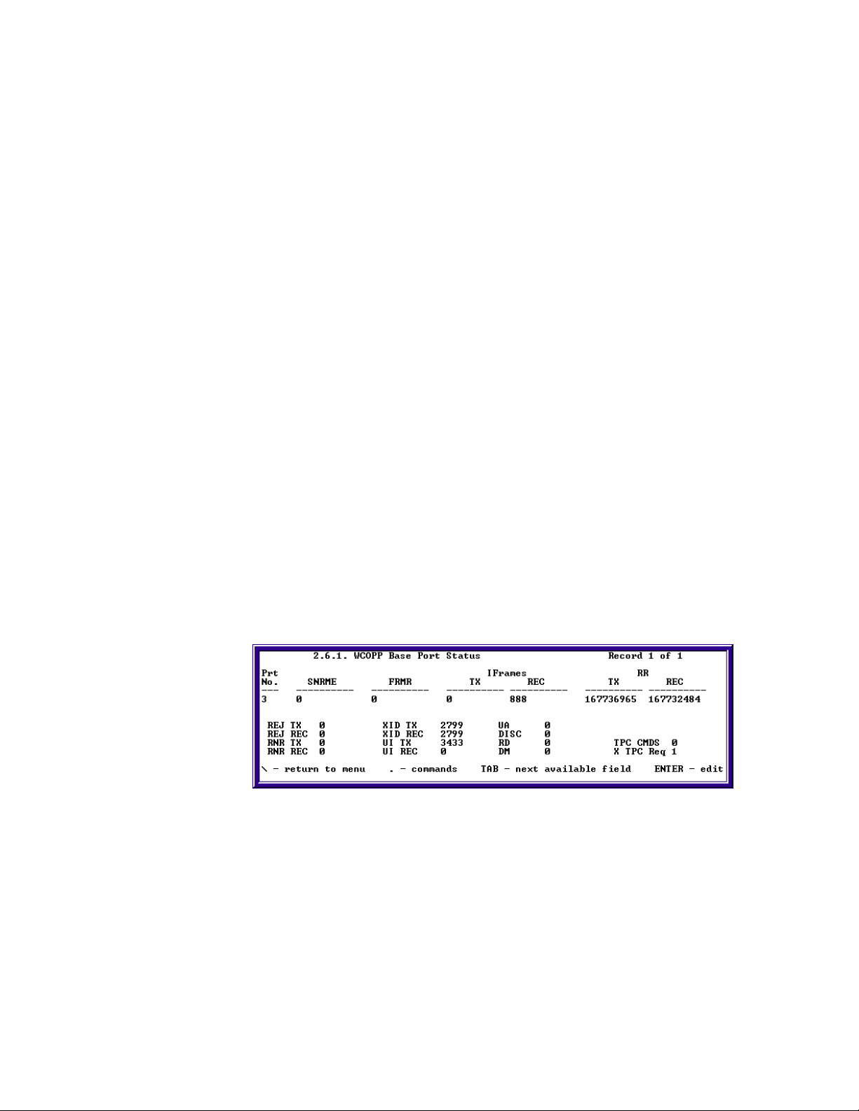
SkyWay Series Multi-Point Operator’s Guide
RF Channel. The channel frequency in MHz:
• 2408 - 2468 MHz
Bytes IN and OUT. The total number of incoming and outgoing bytes on the
port.
Frames IN and OUT. The total number of incoming and outgoing bytes on the
port.
Discards IN and OUT. The total number of incoming and outgoing discarded
frames on the port.
Digital Phase Lock Loop. The number of Digital Phase Lock Loop errors that
occurred on the port.
Frame Length Violation. The total number of frames with Frame Length
received on the port.
Non Octet Aligned Frame. The total number of Framing Alignment errors on
the port.
Abort Sequence. The total number of frames aborted for any reason on the port.
CRC Error. The total number of CRC errors on this port.
Overrun. The number of buffer overflows for the port.
Carrier Detect Lost. The number of times carrier detect was lost.
Underrun. The number of incomplete buffer errors in the communication
processor for the port.
CTS Lost. The number of times clear to send was lost for the port.
Checking WCOPP Base Port Status
Port Number. RF physical port number.
SNRME (Set Normal Response Mode Extended). Command that places the
sub-station in Normal Response Mode (NRM).
FRMR (Frame Reject). A sub-station in NRM transmits this response only when
it receives an invalid frame.
IFrames - TX. The number of Information frames transmitted.
IFrames - REC. The number of Information frames received.
57

Chapter 3: Monitoring SkyWay Series Network
RR (Receive Ready) - TX. The number of Receive Ready frames transmitted.
Indicates that the originating station is ready to receive.
RR (Receive Ready) - REC. The number of Receive Ready frames received.
Indicates that the originating station is ready to receive.
REJ (Reject) - TX. The number of Reject commands sent to all sub-stations.
Rejects are transmitted to request the retransmission of numbered information
frames.
REJ (Reject) - REC. The number of Reject responses received from all sub-
stations.
RNR (Receive Not Ready) - TX. The total number of Receive Not Ready
commands sent to all sub-stations. RNR indicates a temporary busy condition.
RNR (Receive Not Ready) - REC. The total number of Receive Not Ready
responses received from all sub-stations.
UI (Unnumbered Information) - TX. The total number of Unnumbered
Information commands sent to all sub-stations. Used to transmit unreliable
information. Used primarily by WCOPP to transmit bridging and routing
broadcasts.
UI (Unnumbered Information) - REC. The total number of Unnumbered
Information responses received by all sub-stations.
XID (Exchange Station Identification) - TX. The total number of Exchange
Station Identification commands sent to all sub-stations. Allows base and sub to
share information about each others configuration.
XID (Exchange Station Identification) - REC. The total number of Exchange
Station Identification responses received by all sub-stations.
UA (Unnumbered Acknowledgement). This is the affirmative response to a
SNRME, DISC, or SIM command.
DISC (Disconnect). This command terminates other modes and places the sub-
station in disconnected mode.
RD (Request Disconnect). A sub-station desiring to be disconnected by a DISC
command sends this request.
DM (Disconnect Mode). This response is sent by the sub-station to indicate that
it is in disconnected mode.
58

SkyWay Series Multi-Point Operator’s Guide
Checking WCOPP Sub Port Status
Port Number. RF physical port number or sub-station number.
SNRME (Set Normal Response Mode Extended). The number of Set Normal
Response Mode Extended commands sent to the sub-station. Command that
places the sub-station in Normal Response Mode (NRM).
FRMR (Frame Reject). The number of Frame Reject responses sent from the
sub-station when it received an invalid frame. A sub-station in NRM transmits this
response only when it receives an invalid frame.
IFrames - TX. The number of Information frames transmitted.
IFrames - REC. The number of Information frames received.
RR (Receive Ready) - TX. The number of Receive Ready commands sent to the
sub-station. Indicates that the originating station is ready to receive.
RR (Receive Ready) - REC. The number of Receive Ready commands received
from the sub-station. Indicates that the originating station is ready to receive.
REJ (Reject) - TX. The number of Reject commands sent to the sub-station.
Rejects are transmitted to request the retransmission of numbered information
frames.
REJ (Reject) - REC. The number of Reject responses received from the sub-
station.
RNR (Receive Not Ready) - TX. The total number of Receive Not Ready
commands sent to the sub-station. RNR indicates a temporary busy condition.
RNR (Receive Not Ready) - REC. The total number of Receive Not Ready
responses received from the sub-station.
UI (Unnumbered Information) - TX. The total number of Unnumbered
Information commands sent to the sub-station. Used to transmit unreliable
information. Used primarily by WCOPP to transmit bridging and routing
broadcasts.
UI (Unnumbered Information) - REC. The total number of Unnumbered
Information responses received by the sub-station.
XID (Exchange Station Identification) - TX. The total number of Exchange
Station Identification commands sent to the sub-station. Allows base and sub to
share information about each others configuration.
59

Chapter 3: Monitoring SkyWay Series Network
XID (Exchange Station Identification) - REC. The total number of Exchange
Station Identification responses received by the sub-station.
UA (Unnumbered Acknowledgement) . This is the affirmative response to a
SNRME, DISC, or SIM command.
DISC (Disconnect). This command terminates other modes and places the sub-
station in disconnected mode.
RD (Request Disconnect). A sub-station desiring to be disconnected by a DISC
command sends this request.
DM (Disconnect Mode). This response is sent by the sub-station to indicate that
it is in disconnected mode.
Checking WCOPP Sub Poll Status
The WCOPP Sub Poll Status screen contains the substation number, MAC
address, and polling status of each sub that is associated with the base. All subs
begin on the Fast Poll list and work their way down to the Inactive Poll list. Subs
that are constantly exchanging Information frames with the base should be on the
Fast Poll list. After Information frames have not been transmitted for a certain
period of time, or if the sub has not responded to a poll by the base for a certain
number of times, the sub will then move to the Slow Poll list. If while on the Slow
Poll list and Information frames have not been transmitted for a certain period of
time, or if the sub has not responded to a poll by the base for a certain number of
times, the sub will then move to the Inactive Poll list.
While on the Fast Poll list, each sub is constantly polled by the base. When on the
Slow Poll or Inactive Poll list, each sub is polled periodically based on a
configurable value that is set on the WCOPP Base Port Configuration (1.2.3.1.1)
screen.
WCOPP Signal Status
60
Port Number. The port number of the unit for which you are viewing the status.

SkyWay Series Multi-Point Operator’s Guide
Signal Level (-dBm). The detected signal level for the port.
Noise Level (-dBm). The detected noise level for the port.
Signal/Noise (dB). The signal to noise ration.
Rcv Timeouts/sec. The rate of receiver timeouts.
This screen is useful in finding out how much noise may be on your RF link. You
can also see if your receiver is constantly timing out. Monitoring this status screen
will allow you to more quickly solve any problems with your RF link you may
have run into.
ALC/ADC
Automatic Level Control (ALC) is used to periodically adjust the output power to
the target output power if it has changed due to environmental or configuration
changes (temperature, antenna, user added attenuation). It also ensures the unit
output power complies with the rules and mandates of the FCC, and other
regulatory bodies. To access this screen, type “.1234” and press Enter.
Settings changeable by users are:
User Added Attenuation. This setting is used if the maximum output power is
not wanted due to a customer's particular site requirements. For example, the
customer has a short link, and doesn't need full power.
ALC Transmit Power Check Timeout. This setting is the interval between the
ALC checks and adjustments.
Ethernet
Monitoring the Ethernet activity on your SkyWay Series wireless network consists
of two parts:
• Monitoring the Ethernet Port Status
• Monitoring the Ethernet Transceiver Status
The following two sections describe the screens and fields for monitoring Ethernet
activity.
61

Chapter 3: Monitoring SkyWay Series Network
Monitoring the Ethernet Port Status
To monitor the status of the Ethernet Port for the Base unit, type “.2231” and press
Enter. The following screen will be displayed:
This screen displays Ethernet port information on errors and collisions.
The key items to view in this screen are:
Alignment Errors. The number of frames received that are not an integral
number of octets in length and do not pass the FCS check.
FCS Errors. The number of frames received that are an integral number of octets
in length but do not pass the FCS check.
Single Collision Frames. The number of successfully transmitted frames for
which transmission is inhibited by exactly one collision.
Multiple Collision Frames. The number of successfully transmitted frames for
which transmission is inhibited by more than one collision.
SQE Test Errors. The number of times that the SQE TEST ERROR message is
generated by the PLS sublayer.
Deferred Transmissions. The number of frames that experience a delay for the
first transmission attempt because the medium is busy.
Late Collisions. The number of times a collision is detected later than 512 bit-
times into the transmission of a packet.
Excessive Collisions. The number of frames that could not be transmitted due
to excessive collisions.
Internal MAC Transmit Errors. The number of frames that could not be
transmitted due to an internal MAC sublayer transmit error.
Carrier Sense Lost. The number of times that the carrier sense condition was
lost or never asserted when attempting to transmit a frame.
Frames Too Long. The number of frames received that exceed the maximum
permitted frame size.
Internal MAC Received Errors. The number of frames for which reception fails
due to an internal MAC sublayer receive error.
62

Routing
SkyWay Series Multi-Point Operator’s Guide
Monitoring the Ethernet Transceiver Status
To monitor the Ethernet Transceiver Port status, type “.2232” and press Enter to
access the screen. The following screen will be displayed:
This screen displays 3 fields to monitor for Ethernet Port status:
Link Status. Link state of Ethernet port. State is either up or down.
Chip Speed. Link speed of Ethernet port. If Ethernet transceiver is configured as
auto-negotiate, it will automatically determine the chip speed is either 10 Mbps or
100 Mbps.
Duplex Mode. Displays the configuration status of the Ethernet transceiver at
either Full or Half duplex.
Monitoring the routing status consists of two main sections:
• IP Status
• RIP Status
The following sections describe screens and fields for monitoring routing status.
IP Status
Checking IP Protocol Status
Use the IP Protocol Status screen to check the IP protocol status, if packets are
being forwarded correctly, and to troubleshoot routing problems. This screen also
provides you with information on the number and type of packets being routed. To
access this screen, type “.2511” and press Enter.
63

Chapter 3: Monitoring SkyWay Series Network
Incoming Packets. Total number of datagrams received from interfaces,
including those in error.
Incoming Deliveries. The total number of input datagrams successfully
delivered to IP user-protocols (including ICMP).
Forwarding Requests. The number of input datagrams for which this entity was
not their final IP destination, and an attempt was made to find a route toward final
destination.
Outgoing Requests. The total number of IP datagrams that local IP user-
protocols (including ICMP) supplied to IP in requests for transmission.
Incoming Discards. The total number of incoming packets that are discarded
due to header, address, unknown protocol or reassemble failure errors.
Header Errors. The total number of input datagrams discarded due to errors in
their IP headers, including bad checksums, version number mismatches, other
format errors, time-to-live exceeded, errors discovered in processing their IP
options, etc.
Address Errors. The number of input datagrams discarded because the IP
address in their IP header's destination field was not a valid address to be received
at this entity.
Unknown Protocol. The number of locally addressed datagrams received
successfully but discarded because of an unknown or unsupported protocol.
Reassembly Failures. The number of packets that could not be reassembled.
Outgoing Discards. The total number of IP datagrams for which no problem
was found to prevent their transmission to their destination, but which were
discarded (e.g., for lack of buffer space).
No Route Errors. The number of IP datagrams discarded because no route could
be found to transmit them to their destination.
Fragmentation Failures. The number of IP datagrams that have been discarded
because they could not be fragmented as required.
Fragments Created. The number of IP datagram fragments that have been
generated as a result of fragmentation at this entity.
Packets Fragmented OK. The number of IP datagrams that have been
successfully fragmented at this entity.
Reassembly Requests. The number of IP fragments received that need to be
reassembled at this entity.
Packets Reassembled OK. The number of IP packets successfully
reassembled.
Reassembly Timeout. The maximum number of seconds that received
fragments are held while they are awaiting reassembly at this entity.
64
Default Time-to-Live. The Default Time-to-Live (TTL) that is configured in the
IP protocol configuration screen.

SkyWay Series Multi-Point Operator’s Guide
Routing. Indicates that routing is enabled or disabled in the IP protocol
configuration screen.
Checking IP Address Table
Use the IP Address Table to see a summary of the IP Port Configuration. To access
this screen, type “.2512” and press Enter.
IP Port. The physical port configured for IP routing. The Ethernet port is 2; the
RF port is 3.
IP Address. The IP address used to route packets on this port.
IP Mask. The IP Subnet Mask to be used for the IP address.
IP Broadcast. Indicates the least significant bit of the broadcast address for this
interface.
Reassembly Size. The maximum size a reassembled packet can reach.
Checking the IP Address Forward Table
Use the IP Forward Table to view the routing table and make adjustments to route
costs. To access this screen, type “.2513” and press Enter.
Destination IP Address. The network IP address of the destination network.
Next Hop IP Address. The address of the gateway to the destination network.
Destination IP Mask. The network prefix (subnet mask) of the destination
network.
Port Number. Identifies the local interface through which the next hop of this
route can be reached.
Protocol Learned. The method that a route was learned. The possible values are
the following:
• Other - static route with override
• Local - local interface
• Netmgmt - static route
• RIP - Berkeley RIP or RIP-II
65
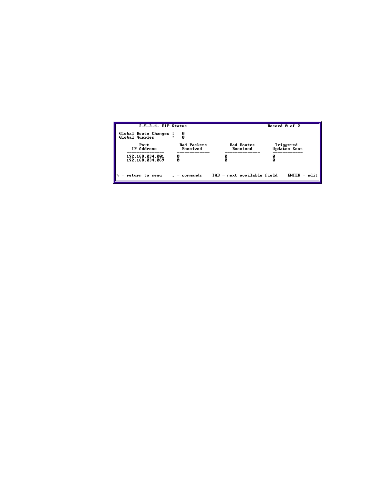
Chapter 3: Monitoring SkyWay Series Network
Age. The number of seconds since this route was last updated or otherwise
determined to be correct. The value for static routes and local routes should be
disregarded.
Cost. The primary routing metric for this route. The semantics of this metric are
determined by the routing protocol specified in the protocol learned field.
Checking the RIP Status
To access this screen, type “.2534” and press Enter.
(On SkyMate - Screen 2.5.3.2)
The following table provides a list of field names and settings:
Global Route Changes. The number of route changes made to the IP Route
Database by RIP. This does not include the refresh of a route's age.
Global Queries. The number of responses sent to RIP queries from other
systems.
Port IP address. The IP Address of this system on the indicated subnet. For
unnumbered interfaces, the value 0.0.0.N, where the least significant 24 bits (N) is
the if Index for the IP Interface in network byte order.
Bad Packets Received. The number of RIP response packets received by the
RIP process which were subsequently discarded for any reason (e.g., a version 0
packet or an unknown command type).
Bad Routes Received. The number of routes, invalid RIP packets, which were
ignored for any reason (e.g. unknown address family or invalid metric).
Triggered Updates Received. The number of triggered RIP updates actually
sent on this interface. This explicitly does NOT include full updates sent
containing new information.
66
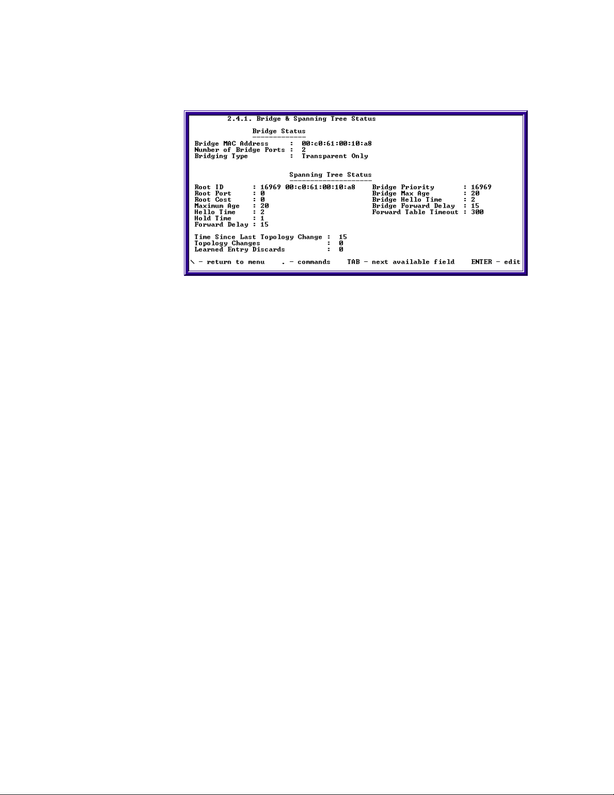
Bridging
SkyWay Series Multi-Point Operator’s Guide
To monitor Bridge and Spanning Tree Status, type “.241” and press Enter.
Bridge Status (Top Half)
Bridge MAC Address. The MAC address used by the bridge as its unique
identifier. The bridge MAC Address concatenated with Bridge Priority creates a
unique Bridge ID used by the Spanning Tree Protocol.
Number of Bridge Ports. Minimum of 2 per unit, the Ethernet and the RF ports.
On the base station, the number of bridge ports is equal to one plus the number of
base sub ports.
Bridging Type. Status is Transparent Only
Bridge Status with Spanning Tree Enabled Status (Bottom Half)
If Spanning Tree is disabled, all fields will have value of zero.
Root ID. The first value is the Bridge Priority of the Root Bridge. The second
value is the bridge identifier of the root of the Spanning Tree. This value is used as
the Root Identifier in all Configuration Bridge PDUs originating from this node.
Root Port. The number of the port offering the lowest cost path from this bridge
to the root bridge.
Root Cost. The cost of the path to the root bridge from this bridge.
Maximum Age. The maximum age (in seconds) set by the Root Bridge.
Hello Time. The hello time (in seconds) set by the Root Bridge.
Hold Time. The interval length (in hundredths of a second) during which no more
than two CBPDUs can be transmitted by this node.
Forward Delay. The forward delay (in seconds) set by the Root Bridge.
Bridge Priority. Bridge priority of this particular bridge configured in Bridge
Configuration screen (1.4.1)
Bridge Max Age. Max age of this particular bridge configured in Bridge
Configuration screen (1.4.1)
67

Chapter 3: Monitoring SkyWay Series Network
Bridge Hello Time. Hello time of this particular bridge configured in Bridge
Configuration screen (1.4.1)
Bridge Forward Delay. Forward delay of this particular bridge configured in
Bridge Configuration screen (1.4.1)
Forward Table Timeout. The timeout period in seconds for aging out
dynamically learned forwarding information on Bridge Forwarding Table screen
(2.4.4) of this bridge. It is configured in Bridge Configuration screen (1.4.1).
Time Since Last Topology Change. The time (in seconds) since the last time a
topology change was detected by the Bridge entity.
Topology Changes. The total number of topology changes detected by the
bridge since the management entity was the last reset or initialized.
Checking Spanning Tree Status and Bridge Status
Checking Spanning Tree Port Status
The Spanning Tree Port Status screen (2.4.3) contains information for each
individual port state if Spanning Tree is enabled. To access this screen, type “.243”
and press Enter. To view the state of the next port, type “.n”
68
Port Number. The physical port number or base sub port number. On a
substation, the bridge ports are 2, Ethernet port, and 3, RF port. On a base station,
the bridge ports are 2, the Ethernet port, and each individual substation number.
Port State. The current state of this bridge port. Either in Blocking, Forwarding,
Listening or Learning.
Port Status. This port will be enabled when configured for bridging.
Port Path Cost. The contribution to the path cost towards the Spanning Tree root
that includes this port.
Designated Root ID. The unique Bridge ID of the root bridge in the
Configuration BPDUs transmitted by the Designated Bridge for the segment to
which the port is attached.
Designated Cost. The path cost of the Designated port of the segment connected
to this port. This value is compared to the Root Path cost field in received bridge
PDUs.
Designated Bridge. The Bridge ID of the bridge that this port considers to be the
Designated Bridge for this port's segment.
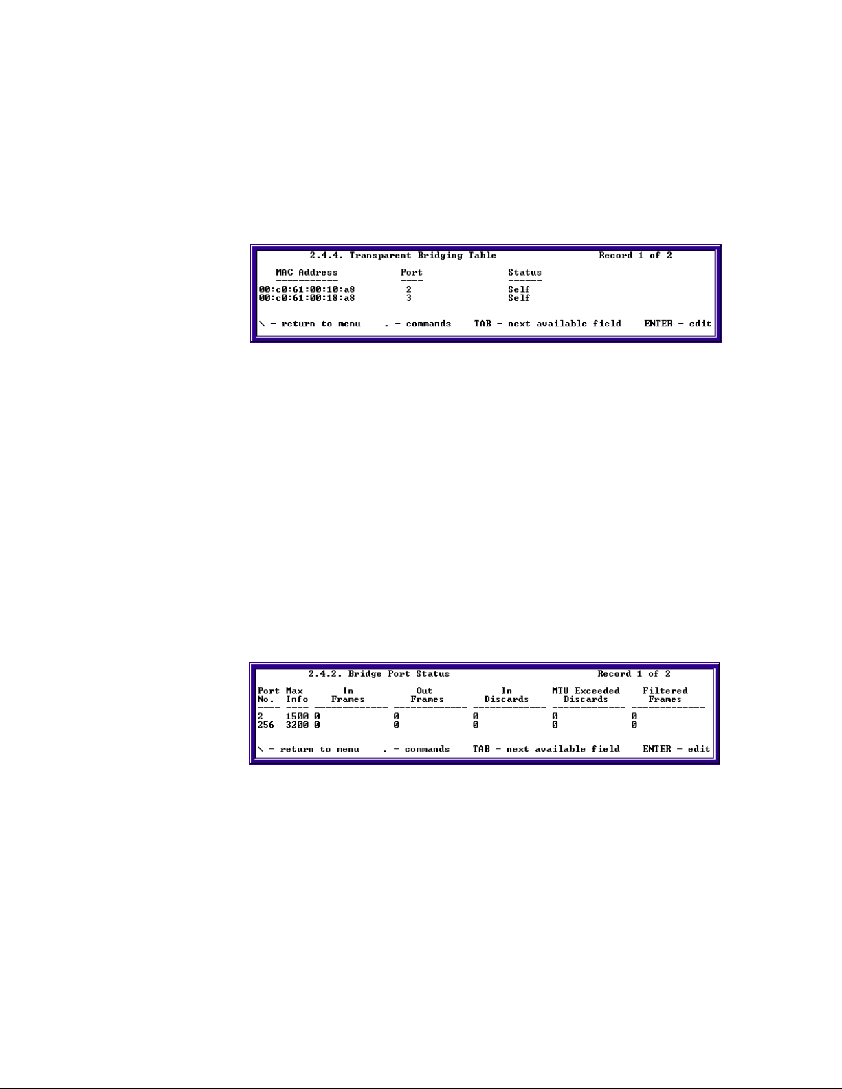
SkyWay Series Multi-Point Operator’s Guide
Designated Port. The Port Identifier of the port on the Designated Bridge for
this port's segment.
Port Forward Transitions. The number of times this port has transitioned from
the Learning state to the Forwarding state.
Checking Transparent Bridging Table Status
The Transparent Bridging Table Status screen (2.4.4) contains information of
host's MAC address, port, and status that the bridge learned.
MAC Address. The MAC address learned from the bridge
Port. The port number where the MAC address was learned
Status. The status of each entry in the table.
Invalid. This entry is no longer valid, but has not been flushed from the table.
Learned. The MAC address was learned from the network.
Self. The MAC address of the ports on the bridge.
Mgmt. This entry was statically entered.
Other. None of these above.
Checking Bridge Port Status/Statistics
The Bridge Port Status screen (2.4.2) contains information on frames in, out,
discarded, or filtered of each individual port of the bridge.
Port No. The physical port number or base sub port number. On a substation, the
bridge ports are 2, Ethernet port, and 3, RF port. On a base station, the bridge ports
are 2, the Ethernet port, and each individual substation number.
Max Info. Maximum size of the information field that this port can transmit or
receive.
In Frames. Total number frames received on this port.
Out Frames. Total number of frames transmitted on this port.
69

Chapter 3: Monitoring SkyWay Series Network
In Discards. The number of frames received on this port that are not forwarded
or destined for a non-forwarding port.
MTU Exceeded Discards. The number of frames that were discarded because
they exceeded the maximum transfer unit size.
Filtered Frames. The total number of frames that are filtered by filters defined in
the Bridge Filter Configuration screen (1.4.3).
Management
Systems Tasks - Status & Control
Task Status and Control Screens
A task is a semi-independent program segment with a dedicated purpose. Because
some tasks are dependent upon other tasks, they cannot be evacuated - only
cycled. Tasks without any dependents can be cycled, evacuated and installed. If
you try to apply an action that does not fit the characteristics, an error message will
appear on the 2.1.3. Error Log Screen.
Task Interdependencies
For tasks that do not have any dependents, they can be cycled, evacuated and
installed in general. However, there are exceptions for some tasks, refer to the
table below for more information. Tasks that are dependants cannot be evacuated
because the depending tasks would be affected.
The following table provides a list of tasks by dependency:
Tasks without Dependants Tasks with Dependents
BOOTP ARP
Bridging Checking Queues
(cannot be Cycled or Evacuated)
Console
(cannot be Cycled or Evacuated)
Diagnostics Ethernet
Ethernet 100 bios diagnostic
(in Bios App)
Init Manager
(cannot be Cycled or Evacuated)
Ram bios diag (in Bios App) ICMP (Ping)
DNS
Fast Ethernet
Flash Manager
70
WCOPP base diag IGMP
WCOPP sub diag IP
RF Management SMC
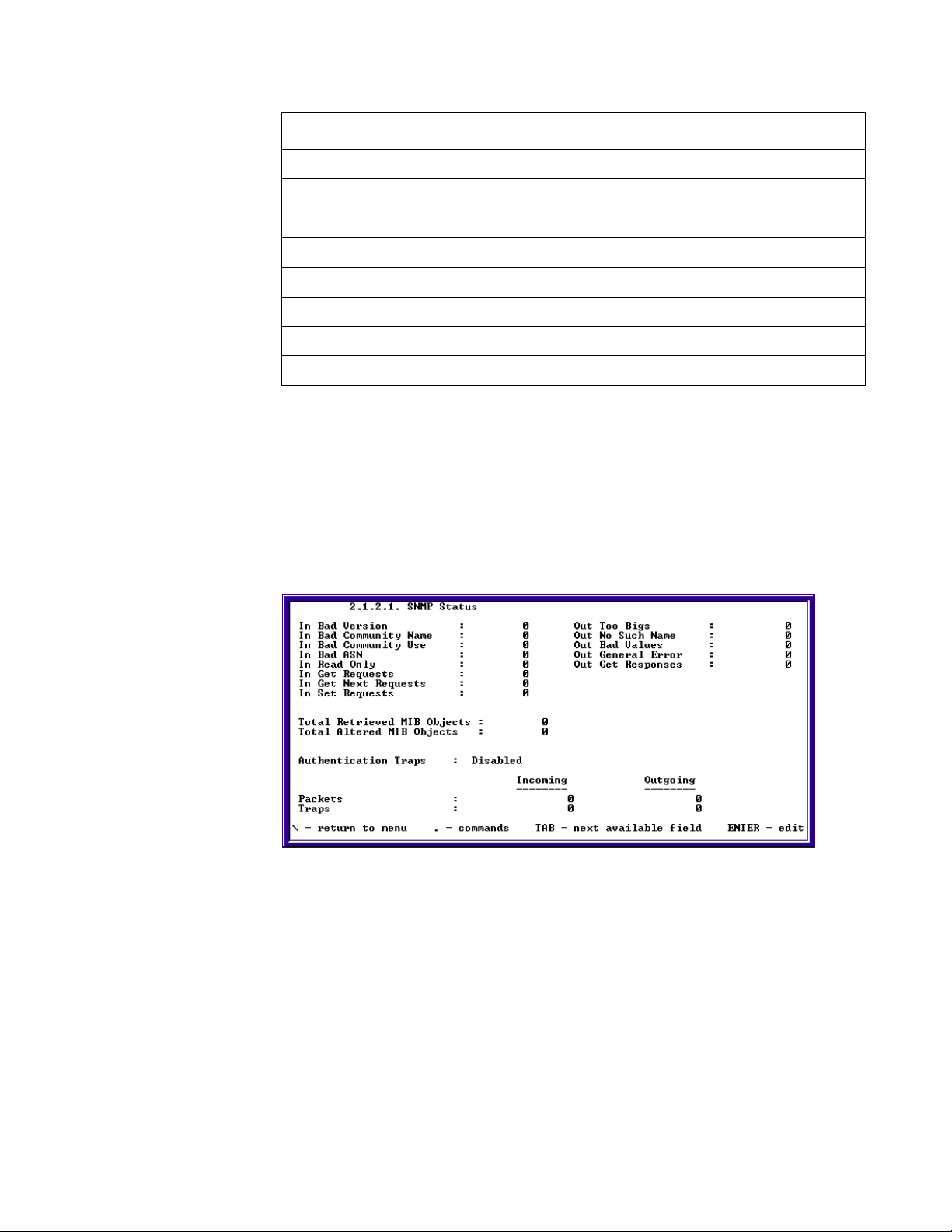
SkyWay Series Multi-Point Operator’s Guide
Tasks without Dependants Tasks with Dependents
Router Redundancy SNMP
RIP TCP
SNTP TFTP
SPI UDP
Task Cycle WCOPP base
Telnet WCOPP sub
Watchdog
Xmodem
Checking SNMP Status and Trap History
You can monitor SNMP traffic and SNMP traps using the following two screens.
• SNMP Status
• SNMP Trap History
SNMP Status
To access this screen, type “.2121” and press Enter.
This screen shows all SNMP traffic. You can see counters for the various SNMP
operations; get, get-next, set etc. The counters on this screen are in direct
correlation with the SNMP group in RFC 1213. All counters are incremented since
the last reset. Typing “.z” will zero or clear all the counters and they will start over
again. At the bottom of the screen, the fields list the number of incoming and
outgoing SNMP packets and traps.
In Bad Version. The total number of SNMP Messages which were delivered to
the SNMP protocol entity and were for an unsupported SNMP version.
71

Chapter 3: Monitoring SkyWay Series Network
In Bad Community Name. The total number of SNMP Messages delivered to
the SNMP protocol entity which used a SNMP community name not known to
said entity.
In Bad Community Use. The total number of SNMP Messages delivered to the
SNMP protocol entity, which represented a SNMP operation that was not allowed
by the SNMP community name in the Message.
In Bad ASN. The total number of ASN.1 or BER errors encountered by the
SNMP protocol entity when decoding received SNMP Messages.
In Read Only. The total number of valid SNMP PDUs which were delivered to
the SNMP protocol entity and for which the value of the error-status field is readonly. It should be noted that it is a protocol error to generate an SNMP PDU which
contains the value readOnly in the error-status field, as such this object is provided
as a means of detecting incorrect implementations of the SNMP.
Out Too Bigs. The total number of SNMP PDUs which were delivered to the
SNMP protocol entity and for which the value of the error-status field is tooBig.
Out No Such Name. The total number of SNMP PDUs which were delivered to
the SNMP protocol entity and for which the value of the error-status field is
noSuchName.
Out Bad Values. The total number of SNMP PDUs which were delivered to the
SNMP protocol entity and for which the value of the error-status field is badValue.
Out General Error. The total number of SNMP PDUs which were delivered to
the SNMP protocol entity and for which the value of the error-status field is
genErr.
Total Retrieved MIB Objects. The total number of MIB objects which have
been retrieved successfully by the SNMP protocol entity as the result of receiving
valid SNMP Get-Request and Get-Next PDUs.
Total Altered MIB Objects. The total number of MIB objects which have been
altered successfully by the SNMP protocol entity as the result of receiving valid
SNMP Set-Request PDUs.
In Get Requests. The total number of SNMP Get-Request PDUs which have
been accepted and processed by the SNMP protocol entity.
In Get Next Requests. The total number of SNMP Get-Next PDUs which have
been accepted and processed by the SNMP protocol entity.
In Set Requests. The total number of SNMP Set-Request PDUs which have
been accepted and processed by the SNMP protocol entity.
Out Get Responses. The total number of SNMP Get-Response PDUs which
have been generated by the SNMP protocol entity.
72
Authentication Traps. Indicates whether the SNMP agent process is permitted
to generate authentication-failure traps
Packets In . The total number of Messages delivered to the SNMP entity from
the transport service.

SkyWay Series Multi-Point Operator’s Guide
Packets Out. The total number of SNMP Messages which were passed from the
SNMP protocol entity to the transport service.
Traps. The total number of SNMP Trap PDUs which have been generated by the
SNMP protocol entity.
SNMP Trap History
This screen displays the trap number, description, value (OID), and date and time
the trap occurred. Authentication Traps must be enabled on the Network
Management Security Configuration screen before the SNMP agent process is
permitted to generate authentication traps.
Trap #. A number that corresponds to the trap log table index.
Trap Description. A description of the type of trap that occurred.
Value. The value of the first trap variable or zero.
Date & Time. The date and time the trap occurred.
Protocols & Applications
TCP Statistics
To check Transmission Control Protocol (TCP) Configuration, type “.153” and
press Enter. The following screen will appear.
Max TCP Connection. Range: 1-10. Maximum number of TCP connection
permitted; range is between 1-10.
Max Retransmissions. Value is 3. Maximum number of segments that can be
retransmitted within a session. Value is 3.
Max Segment Life. Value is 600. Maximum number of connection maintained
throughout a session's lifetime by the acknowledgement of each octet of data
transmitted
73

Chapter 3: Monitoring SkyWay Series Network
Max Retransmit Time. Range is 50-40000. Maximum time given to a segment
after it has been lost due to network failure or where the segment is received
corrupted.
Min Retransmit Time. Range is 10-20000. Minimum time given to a segment
after it has been lost due to network failure or where the segment is received
corrupted.
Acknowledge Delay Time. Range is 0-1000. The time it takes for the receiving
TCP to acknowledge the segment being transmitted.
Max Persist Time . Range is 100-99999. Maximum time allowed to sending a
packet out.
Max Segment Size. Range is 256-1000. Maximum received segment size that
the transmitting TCP is willing to accept. Note that the Maximum segment size is
always 32 bits in length.
Max Packet Size. Range is 256-3000. Maximum received packet size that the
transmitting TCP is willing to accept.
Checking UDP Status
You can check the UDP (user datagram protocol) status using the following
screen:
Incoming Datagrams. The total number of UDP datagrams received.
Outgoing Datagrams. The total number of UDP datagrams sent.
Errors. The number of received UDP datagrams that could not be delivered for
reasons other than the lack of an application at the destination port (e.g. bad UDP
header checksum.)
No Port. The total number of received UDP datagrams for which there was no
application at the destination port.
74
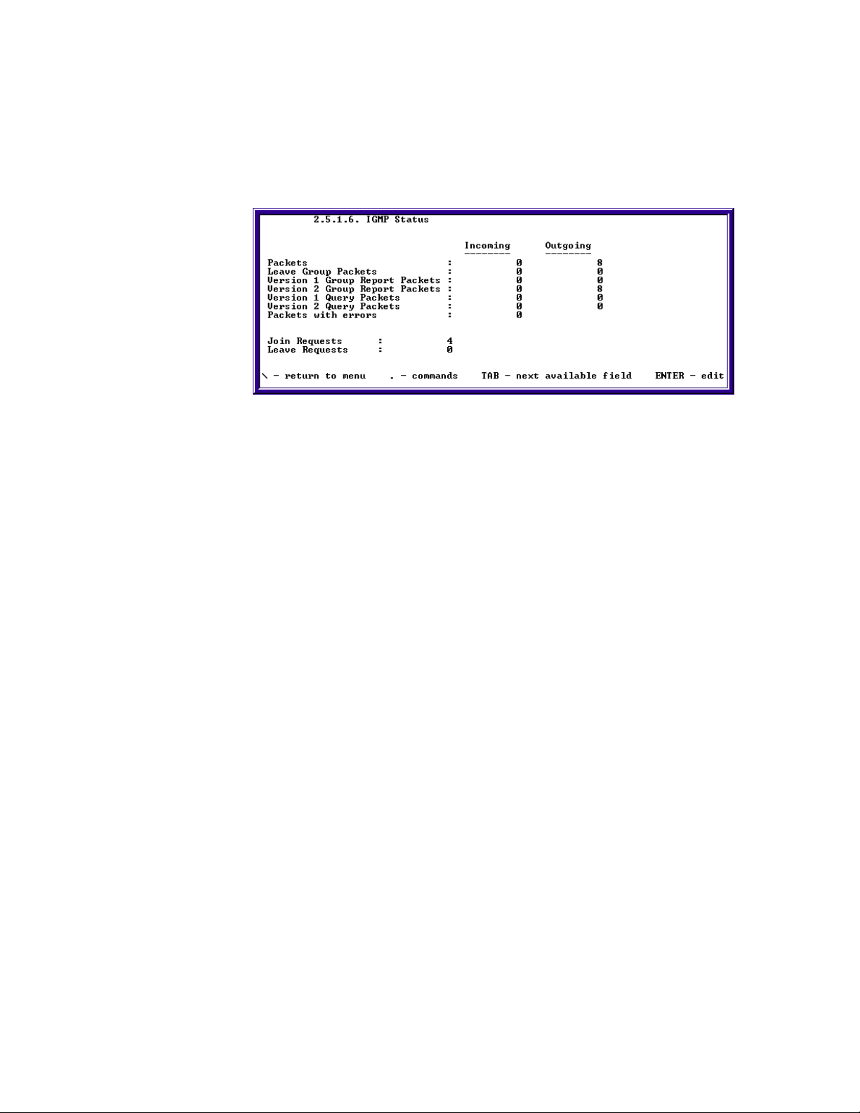
SkyWay Series Multi-Point Operator’s Guide
IGMP
Checking IGMP Activity
You can check the IGMP (Internet Group Management Protocol) status by typing
'.2516” and pressing Enter. The following screen will be displayed:
Checking the IGMP Status allows you to monitor incoming and outgoing requests
and replies, incorrect lengths and opcodes, exceeded HOPS, and timeouts to the
system.
Incoming Packets. The number of IGMP packets received.
Outgoing Packets. The number of IGMP packets sent.
Incoming Version 1 Group Report Packets. The number of IGMP version 1
group report packets received.
Outgoing Version 1 Group Report Packets. The number of IGMP version 1
group report packets sent.
Incoming Version 2 Group Report Packets. The number of IGMP version 2
group report packets received.
Outgoing Version 2 Group Report Packets. The number of IGMP version 2
group report packets sent.
Incoming Version 1 Query Packets. The number of IGMP version 1 query
packets received.
Outgoing Version 1 Query Packets. The number of IGMP version 1 query
packets sent.
Incoming Version 2 Query Packets. The number of IGMP version 2 query
packets received.
Outgoing Version 2 Query Packets. The number of IGMP version 2 query
packets sent.
Incoming Packets with Errors. The number of IGMP packets containing errors
received.
Join Requests. The number of IGMP Join Requests sent.
Leave Requests. The number of IGMP Leave Requests sent.
75

Chapter 3: Monitoring SkyWay Series Network
Checking ICMP Status
The ICMP Status screen provides details on the type of ICMP datagrams that are
received and transmitted. To access this screen, type '.2515” and press Enter.
In this screen, the Incoming column reflects the number of ICMP packets received
by the SkyWay unit, and the Outgoing column displays the number transmitted.
This screen is read-only.
Packets. This is the total of all ICMP events (Incoming and Outgoing) listed in
the rest of this table.
Timestamp Requests. The number of ICMP Timestamp request messages sent
and received.
Timestamp Replies. The number of ICMP Timestamp reply messages sent and
received.
ICMP-Specific Errors. The number of ICMP messages determined as having
ICMP-specific errors (bad ICMP checksums, bad length, etc.) sent and received.
Destination Unreachable Errors. The number of ICMP Destination
Unreachable messages sent and received.
Time Exceeded Errors. The number of ICMP Time Exceeded messages sent
and received.
Address Mask Requests. The number of ICMP Address Mask Request
messages sent and received.
Address Mask Replies. The number of ICMP Address Mask Reply messages
sent and received.
Echo Requests. The number of ICMP Echo Request messages sent and
received.
Echo Replies. The number of ICMP Echo Reply messages sent and received.
Source Quenches. The number of ICMP Source Quenches messages sent and
received.
76
Router Redirects. The number of ICMP Redirect messages sent and received.
Parameter Problems. The number of ICMP Parameter Problem messages sent
and received.
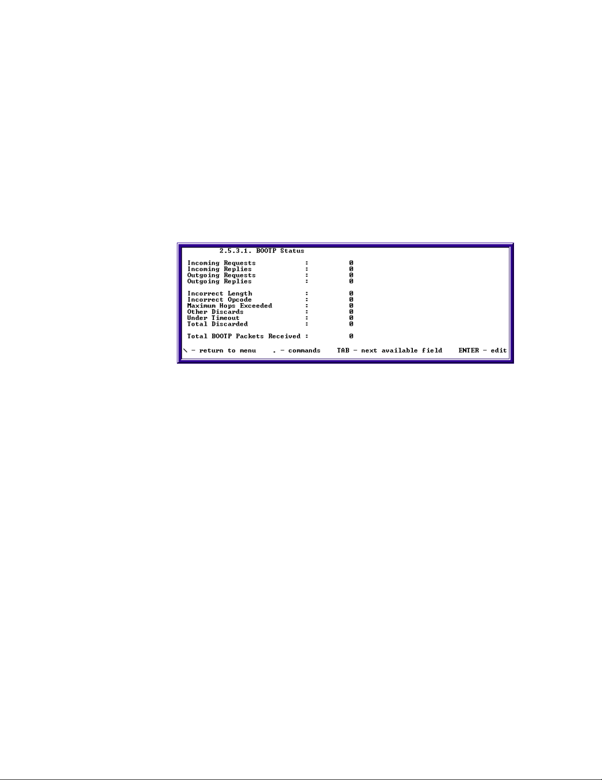
SkyWay Series Multi-Point Operator’s Guide
Checking BOOTP and DHCP Status
You can check the BOOTP (BOOTstrap Protocol) and DHCP (Dynamic Host
Configuration Protocol) status using the following three screens:
• BOOTP Status
• DHCP Declines
• DHCP Statistics
Monitoring BOOTP Status
Checking the BOOTP Status allows you to monitor incoming and outgoing
requests and replies, incorrect lengths and opcodes, exceeded HOPS, and timeouts
to the system. To access this screen, type '.2531” and press Enter.
Incoming Requests. The number of incoming BOOTP requests received.
Incoming Replies. The number of incoming BOOTP replies received.
Outgoing Requests. The number of BOOTP requests forwarded.
Outgoing Replies. The number of BOOTP replies forwarded.
Incorrect Length. The number of BOOTP packets received that were of
incorrect length.
Incorrect Opcodes. The number of BOOTP packets received that contained an
incorrect opcode.
Maximum Hops Exceeded. The number of BOOTP packets received that
exceeded the maximum hop count.
Other Discards. The number of BOOTP packets received that were discarded
for other reasons.
Under Timeout. The number of BOOTP packets received that timed out.
Total Discards. The total number of BOOTP packets received that were
discarded.
Total BOOTP Packets Received. The total number of BOOTP packets
received.
77

Chapter 3: Monitoring SkyWay Series Network
Monitoring DHCP Declines
Checking the DHCP Declines table allows you to monitor the addresses removed
from the DHCP server's address pool due to DHCPDECLINE messages received
from DHCP clients. This screen also allows you to return declined addresses to the
DHCP server's address pool. To access this screen, type '.2532” and press Enter.
Assign Type. The type of pool that the address was obtained from, (Automatic or
Manual).
IP Address. The IP address declined by a DHCP client.
Status. The current state of the address as viewed by the DHCP server. The state
can be changed to (Accept) to return the IP address to the DHCP server's address
pool.
Monitoring DHCP Statistics
Checking the DHCP Statistics allows you to monitor the DHCP server
configuration and activity. To access this screen, type '.2533” and press Enter.
Number of Pools. The number of configured address pools.
Number of Declined Addresses. The number of addresses declined by DHCP
clients.
Number of Manual Bindings. The number of clients configured via the DHCP
Manual Configuration that are bound to the server.
Number of Automatic Bindings. The number of clients configured via the
standard DHCP Address Pools that are bound to the server.
Number of Failed Requests. The number of requests not fulfilled by the DHCP
server (e.g. the address pools are exhausted.).
78

SkyWay Series Multi-Point Operator’s Guide
Monitoring DHCP Client Protocol Status
This screen can be used to configure the DHCP client. To access this screen, type
“.1542” and press Enter.
DHCP Client DB Version. The DHCP client database version number.
When a new DHCP client database is being created, this field must be changed to
a number greater than the DHCP client's DHCP Client DB Header Tag, which is 0
by default.
DHCP Client DB Header Tag. The current DHCP client database version
number.
When the DHCP client is contacting the next server to use in its bootstrap process,
it will compare its current DHCP Client DB Header Tag to the DHCP Client DB
Header Tag of the database located on the next server in its bootstrap process. If
the tag of the database located on the next server in its bootstrap process is greater
than the DHCP client's current tag, the database will be downloaded and the
DHCP client's tag will be changed to the downloaded database's tag; otherwise,
the database will not be downloaded.
Monitoring SNTP
SNTP is a utility (application) used to synchronize clocks on subs or clients with
bases or servers. SNTP is monitored by checking time and date of the unit on
screen 1.1.4 System Clock Configuration. Only SNTP clients will reflect any
change in time. However, clients should synchronize their clock with server
clocks. This can be done in the following three steps:
1. From the Main Menu, type “114” and go to the System Clock Configuration
screen.
2. Monitor and record time of the unit.
3. Exchange SNTP packets as described in “SNTP Configuration” on page42.
4. Return to the System Clock Configuration screen (1.1.4) and monitor and
record time of the unit.
79

Chapter 3: Monitoring SkyWay Series Network
Monitoring the ARP Cache
To access this screen, type “.2514” and press Enter.
This screen will contain all the ARP entries learned.
Port. The port which the ARP entry learned from, either port 2, Ethernet port or
port 3, RF port.
MAC. The MAC address of the host learned.
IP Address. The IP address of the host learned.
80

Appendix A: RunTime & Bios Application Menu
Trees
Run Time Application Menu Tree
Main Menu
1. Configuration Menu
1. System Configuration
1. Network Management Security Configuration
2. Network Management System Configuration
3. User Access Configuration
1. Add a User
2. Users
4. System Clock Configuration
5. Activation Key Configuration
2. Port Configuration
1. Serial Port Configuration
1. Serial Port Configuration
2. Serial Transceiver Configuration
2. Ethernet Port Configuration
1. Ethernet Port Configuration
2. Ethernet Transceiver Configuration
3. RF Port Configuration
1. RF Link Layer Configuration
1. RF Base Port Configuration
2. RF Sub Port Configuration
3. WCOPP-AP Configuration
2. RF Diagnostic Port Configuration
3. RF Transceiver Configuration
81

Appendix A: RunTime & Bios Application Menu Trees
4. RF Automatic Level Control
5. RF Bandwidth Management Configuration
3. Task Configuration
4. Bridge Configuration
1. Bridge Configuration
2. Bridge Ports Configuration
3. Bridge Filters Configuration
5. Router Configuration
1. IP Configuration
1. IP Protocol Configuration
2. IP Port Configuration
3. IP Static Routes Configuration
4. IP Filters Configuration
2. IGMP Port Configuration
3. TCP Configuration
4. BOOTP/DHCP Configuration
1. BOOTP Protocol Configuration
2. DHCP Client Configuration
3. DHCP Server Configuration
1. DHCP Server Protocol Configuration
2. DHCP Address Pool Configuration
3. DHCP Manual Configuration
5. RIP Configuration
1. RIP Protocol Configuration
2. RIP Port Configuration
6. Configuration Summary
82
2. Status and Control
1. System Status and Control
1. General Status and Control
2. Network Management Status
1. SNMP Status
2. SNMP Trap History
3. Event Log Screen
2. Port Status and Control
1. Generic Port Status and Control
2. Serial Port Status
3. Ethernet Port Status
1. Ethernet Port Status
2. Ethernet Transceiver Status
4. RF Port Status
1. RF Port Status

SkyWay Series Multi-Point Operator’s Guide
2. RF BW Management Status
3. Task Status and Control
4. Bridge Status
1. Bridge & Spanning Tree Status
2. Bridge Port Status
3. Spanning Tree Port Status
4. Transparent Bridging Table
5. Router Status
1. IP/ARP/ICMP/IGMP
1. IP Protocol Status
2. IP Address Table
3. IP Forward Table
4. ARP Table
5. ICMP Status
6. IGMP Status
2. UDP/TCP
1. UDP Status
2. UDP Listen Table
3. TCP Status
3. BOOTP/DHCP/RIP
1. BOOTP Status
2. DHCP Declines
3. DHCP Statistics
4. RIP Status
6. Wireless Connection Oriented Polling Protocol Status
1. WCOPP Base Port Status
2. WCOPP Sub Port Status
3. WCOPP Sub Poll Status
4. WCOPP Signal Status
5. WCOPP-AP Status
7. Status Summary
3. Utilities
1. File Transfer Utilities
1. TFTP File Transfer
1. TFTP Server Configuration
2. TFTP File Transfer
2. Ymodem File Transfer
3. Xmodem File Transfer
4. File Directory
2. Ping Utility
83

Appendix A: RunTime & Bios Application Menu Trees
3. Flush Tables
4. Remote RF Configuration
5. SNTP Utility
4. Diagnostics
1. RF Base Radio Test
2. RF Sub Radio Test
5. Start Application
6. Log Off
Bios Application Menu Tree
1. Configuration Menu
1. System Configuration
2. Port Configuration
1. Serial Configuration
1. Serial Port
2. Serial Transceiver
2. Ethernet Configuration
1. Ethernet Port
2. Ethernet Transceiver
3. Task Configuration
2. Status and Control
1. Task Status and Control
3. Diagnostics
1. DRAM Diagnostics
2. Flash Diagnostics
3. Ethernet Diagnostics
4. Loop Through All Diagnostics
4. Files
5. Utilities
84
1. YMODEM Receive/Send
2. XMODEM Receive/Send
3. Configuration Database Service
4. Real Time Clock

6. Event Log
7. User Screens
1. Add a User
2. Users
8. Reset SkyWay
9. Start Application
A. Log Off
SkyWay Series Multi-Point Operator’s Guide
85

Appendix A: RunTime & Bios Application Menu Trees
86
 Loading...