

Page 1
www.solectek.com
SOLECTEK CORPORATION
6370 Nancy Ridge Dr.
Suite 109
San Diego, CA 92121
858-450-1220
fax 858-457-2681
i
Page 2

Copyright Solectek Corporation 2000
All rights reserved. Reproduction, adaptation, or translation without prior written permission is prohibited, except as allowed under the copyright laws.
Revision number 1.01
First edition, March 2000
Printed in USA
The information contained in this document is subject to change without notice.
Solectek Corporation makes no warranty of any kind with regard to this material,
including, but not limited to, the implied warranties or merchantability and fitness for a
particular purpose.
Solectek Corporation shall not be liable for errors contained herein or for incidental or
consequential damage in connection with the furnishing, performance, or use of this
material.
ii
Page 3

Regulatory Information
The SkyWay Series Wireless Bridge/Router operates in the 2.4 GHz band, complies
with the IEEE 802.1D MAC bridging standard and supports SNMP monitoring if IP
routing is enabled.
Federal Communications Commission (FCC) Radio Frequency Interference Statement
This device complies with Part 15 of FCC Rules. Operation of this device is subject to
the following two conditions:
• It may not cause harmful interference.
• It must accept any interference that may cause undesired operation.
Information to the User
In order to comply with FCC RF exposure requirements, a minimum separation distance of 27 in. must be maintained between the antenna and any persons. When
installing the antenna, ensure that this clearance is maintained while the product is in
operation.
This device must be installed and used in strict accordance with the manufacturer's
instructions. However, there is no guarantee that interference to radio communications will not occur in a particular commercial installation. In case the device does cause
harmful interference with an authorized radio service, the user/operator shall promptly
stop operating the device until harmful interference has been limited. Solectek Corporation is not responsible for any radio or television interference caused by unauthorized modification of this device or the substitution or attachment of connecting cables
and equipment other than specified by Solectek Corporation. The correction of interference caused by such unauthorized modification, substitution, or attachment will be
the responsibility of the user.
i
Page 4

Steps for
minimizing or
eliminating radio
and television
interference:
• Change the channel
• Reorient the radio or TV receiving antenna.
• Relocate the computer and SkyWay Series Wireless Bridge/Router unit with
respect to the receiver.
• Plug the computer and SkyWay Series Wireless Bridge/Router into a different
outlet so the computer and bridge/router are on different branch circuits.
If necessary, consult the dealer or an experienced radio/TV technician for additional
suggestions. You may find the booklet called “How to Identify and Resolve Radio-TV
Interference Problems” prepared by the Federal Communications Commission helpful. The booklet is available from the U.S. Government Printing Office, Washington,
D.C., 20402, as stock number 004-000-00345-4.
This product was FCC certified under test conditions that included the use of shielded
I/O cables and connectors between system components. To be in compliance with
FCC regulations, the user must use shielded cables and connectors and install them
properly.
Point-to-Point (CFR 15.247 b)
Solectek ensures that its intentional radiators that operate in the ISM band (2.4 GHz)
and that are configured with directional antennas for point-to-point use will always
comply with FCC transmitter power mandates.
This transmitter output power control does not diminish user’s or installer’s responsibility to ensure that the point-to-point system is used in the manner prescribed by the
Code of Federal Regulations. This directive forbids and excludes the use of point-tomultipoint systems and omni-directional applications as well as multiple co-located
intentional radiators.
Radio Transmission Notice
This product is a low power (less than 1 Watt), direct-sequence, spread-spectrum
radio system pre-set to transmit and receive signals in the 2.4-2.4835 GHz frequency
band. This product has been certified by the U.S. Federal Communications Commission for use in the United States of America in that band. The manufacturer makes no
representation as to the availability of the above-mentioned frequency band for such
use in other countries.
Any prospective user of this product outside the United States of America should, prior
to such use, contact the government department or other agency responsible for
assigning radio frequencies in the country in which use is proposed to determine
whether such department or agency has any objection to operation of the product in
the 2.4-2.4835 GHz band, and whether there are any other local devices generating
signals in that band which might be expected to interfere with the operation of this
product.
ii
Page 5

Regulatory Information
The manufacturer shall not be responsible for any operation of this product which is in
violation of local law, creates interference harmful to other local devices, or results in a
malfunction of this product caused by outside interference.
End User License Agreement
Notice: Read below before installing and using this device. Installing and using this
device indicates your acceptance of these terms and conditions. If you do not accept
the terms, you must return the unused device and all related software immediately.
You may not use, copy, modify, or transfer the enclosed device, related documentation, or any software programs residing in or included with the device (collectively, the
“product”), except as expressly provided in this license.
License. The technology and intellectual property embodied in the Product (the
“Technology”) are licensed, not sold, to you. You have a nonexclusive and nontransferable right only to connect the Product to and to use the Technology with a single
license control utility. You may not modify or make inoperable authorization keys or
license control utilities. You may not transfer, sublicense or assign a license to the Product or the Technology to another party except in accordance with Solectek's Product
License Transfer Policy in effect at the time of such license grant.
You understand that the Technology belongs to Solectek or its third party licensors (collectively, “Solectek”), and they have the right to enforce this license. You agree to keep
confidential and use your best efforts to prevent and protect the contents of the Technology from unauthorized disclosure or use. Solectek reserves all rights not expressly
granted to you.
Limitations on use. You may not disclose or make available the Product or the
Technology to any other party or permit others to use it except your employees and
agents who use it on your behalf and who have agreed to these license terms. You
may not do any of the following with or to the Product or the Technology: (a) make
copies (except for backup or archival copies); (b) rent, lease or distribute copies; (c)
make any alteration, modification, translation or the like without the prior written consent of Solectek; or (d) reverse engineer, reverse assemble, reverse compile or otherwise engage in similar manipulation. Any full or partial copy of the Product must include
all copyright and other proprietary notices which appear on or in the Product.
You must maintain adequate records to be able to control use of the Product and the
Technology according to these license terms. These records must match the use of the
Product and the Technology to the license grants. Solectek may require you to make
these records available to Solectek or the third party developer or owner of the applicable portion of the Product.
The term “authorization key” includes any unique series of data elements that is to be
installed and enabled in a license control utility to allow use of the Product. Authorization keys may be installed and enabled for use in only one license control utility at any
one time. Authorization keys are non-transferable and confidential and must be
destroyed on termination of this license. Unless otherwise specified, you may print
electronic Product documentation as reasonably necessary to exercise your right to
use the Product.
iii
Page 6

Terms and Limitations. This license is effective until terminated. You may terminate
this license at any time by returning the Product to Solectek. This license automatically
terminates if you fail to comply with its terms and conditions. You agree that upon such
termination you will return the Product to Solectek, together with any other material
you have received from Solectek in connection with the Product.
U.S. governing law and export restrictions. This license will be governed by
the laws (other than choice of law principles) of the State of California, and in no event
will it be governed by the U.N. convention of the international sale of goods. You
acknowledge that the laws and regulations of the United States restrict the export and
re-export of the Product and any related technical data. You agree that you will not
export or re-export the Product or any related technical data in any form without first
obtaining the appropriate United States and foreign government approval.
U.S. Government Restricted Rights Legend
The Product is provided with Restricted Rights. Use, duplication, reproduction or disclosure by the Government is subject to restrictions in subdivision (c)(1)(ii) of the Rights
in Technical Data and Computer Product clause at 252.227-7013 and in subparagraphs (a) through (d) of the Commercial Product-Restricted Rights Clause at 52.227-
19. Contractor/Manufacturer is Solectek, 6370 Nancy Ridge Drive, Suite 109, San
Diego, California.
iv
Page 7

Introduction
Introduction
The products and software programs described in this Users’ Guide are licensed products of SOLECTEK and are fully copyrighted. The information within this Operator’s
Guide is proprietary and also is copyrighted.
Information in this Operator’s Guide is subject to change without notice. While every
precaution has been taken in the preparation of this Guide, SOLECTEK assumes no
responsibility for inaccuracies. The Operator’s Guide may not be reproduced or transmitted in any form or by any means, electronic or mechanical, including photocopying,
recording, or information retrieval systems, for any purpose other than the purchaser’s
personal use, without the expressed, written permission of SOLECTEK.
It is the policy of SOLECTEK to improve its products as new technology, components,
software, and firmware become available. SOLECTEK Corporation, therefore,
reserves the right to change specifications without prior notice. Furthermore, all features, functions, and operations described herein may not be marketed by SOLECTEK
in all parts of the world.
SOLECTEK is the name and trademark of SOLECTEK Corporation. SkyWay is a
trademark of SOLECTEK Corporation.
SOLECTEK does not warrant that the hardware and software of its product will function as intended in every environment and application, and makes no warranty and
representation, either implied or expressed, with respect to the quality, performance,
merchantability, or fitness for every purpose.
Other trademarks:
IBM and AT are registered trademarks of International Business Machines Corporation.
Microsoft and MS-DOS are registered trademarks of Microsoft Corporation. Novell
and NetWare are registered trademarks of Novell, Inc. Other trademarks are the
property of their respective holders.
Copyright January 2000 SOLECTEK Corporation, San Diego, California, U.S.A.
All Rights Reserved. Printed in the U.S.A.
Tel: (858)450-1220
Web Site: www.solectek.com
Part Number:
v
Page 8

Contact Information
If the information in this Users’ Guide does not answer your questions, please contact
SOLECTEK Corporation’s Technical Support Department. Our friendly and knowledgeable Technical Support staff is available to answer your questions Monday through
friday, 8:00 a.m. to 5:00 p.m., Pacific Time. If you prefer, you can submit questions to
our 24-hour fax number or by e-mail.
Voice support: (858)450-1220
24-hour fax number: (858)457-2681
E-mail address: support@solectek.com
To handle your call as quickly and effectively as possible, please have the following
information ready before you call.
• The model you are using (SkyWay Bridge/Router).
• The type of Ethernet connection your SkyWay Bridge/Router has (10BaseT or
100BaseF).
• The network to which you are connected (for example, Novell NetWare,
version xx).
• The application you were using when you encountered the problem (for
example, Word for Windows, version 7.0).
• Any symptoms or error codes that accompanied the problem (for example,
activities were suspended or a “123ABC” error code appeared.).
• The results of the most recent bench test (see Chapter 3).
vi
Page 9

Warranty
Warranty
One Year Limited Warranty
Subject to the conditions and procedures set forth below during the warranty period,
Solectek will repair or replace, at Solectek’s option, such Solectek products or parts
thereof which, on inspection by Solectek, are found to be covered by the limited warranties set forth below. The warranty period for new hardware products, which are
listed on Solectek’s MSRP Price List at time of purchase, is twelve months from the
date of shipment from Solectek. The warranty period for spare parts and R- part numbers is ninety days from the date of shipment from Solectek. If you think there is a
problem or defect with your Solectek product:
• Contact Solectek’s Technical Support Department between 8:00 a.m. and
5:00 p.m., Pacific Time at (858) 450-1220, or via fax at (858) 457-2681, or via
e-mail at support@solectek.com. The Solectek Technical Support Representative will discuss your problem to confirm the defect. After business hours,
please leave a voicemail or send an e-mail or fax. A Technical Support Representative will respond to you the next business day.
• If warranty or return service is needed, you will receive a Return Material
Authorization (RMA) number. At no time should Solectek products be sent
back without a valid RMA number. Solectek accepts no responsibility for unauthorized returns.
You agree to pay for shipping to Solectek. If the product is under warranty, Solectek
You agree to pay for shipping to Solectek. If the product is under warranty, Solectek
You agree to pay for shipping to Solectek. If the product is under warranty, Solectek You agree to pay for shipping to Solectek. If the product is under warranty, Solectek
will pay for shipping of the repaired or replacement product to you via ground trans-
will pay for shipping of the repaired or replacement product to you via ground trans-
will pay for shipping of the repaired or replacement product to you via ground trans-will pay for shipping of the repaired or replacement product to you via ground transportation to your location in the United States. For installations outside the continental
portation to your location in the United States. For installations outside the continental
portation to your location in the United States. For installations outside the continental portation to your location in the United States. For installations outside the continental
U.S., Solectek will pay for shipping via ground transportation to the freight forwarder of
U.S., Solectek will pay for shipping via ground transportation to the freight forwarder of
U.S., Solectek will pay for shipping via ground transportation to the freight forwarder of U.S., Solectek will pay for shipping via ground transportation to the freight forwarder of
your choice located in the continental United States. Any other freight arrangements
your choice located in the continental United States. Any other freight arrangements
your choice located in the continental United States. Any other freight arrangements your choice located in the continental United States. Any other freight arrangements
will be at customer expense.
will be at customer expense.
will be at customer expense.will be at customer expense.
Solectek shall not be liable for any damage caused to the product in transit. You
Solectek shall not be liable for any damage caused to the product in transit. You
Solectek shall not be liable for any damage caused to the product in transit. You Solectek shall not be liable for any damage caused to the product in transit. You
acknowledge and agree you will bear all risk of loss or damage to the product while
acknowledge and agree you will bear all risk of loss or damage to the product while
acknowledge and agree you will bear all risk of loss or damage to the product while acknowledge and agree you will bear all risk of loss or damage to the product while
in transit.
in transit.
in transit.in transit.
Send return shipments to:
Solectek Corporation
6370 Nancy Ridge Drive, Suite 109
San Diego, CA 92121-3212
ATTN: RMA # ________
• Pack products securely, to prevent damage in transit. Be sure the RMA number is clearly visible on the outside of the return shipping carton.
• Returned Solectek products must include all other components from the original package, including the hardware, cables, connectors, software diskettes,
and user manual(s) unless otherwise stipulated by Solectek.
• Enclose a copy of the original purchaser’s proof of purchase, if needed to support warranty claim. (See details in LIMITATIONS section below.)
vii
Page 10

After inspecting the failed unit, Solectek will repair or replace materially defective parts
or components. All products that are replaced become the property of Solectek. If
upon inspection by Solectek, a unit returned under warranty is deemed to be damaged
or out of warranty for any reason, (see LIMITATIONS section below), Solectek will
contact the customer with a price for the repair or replacement unit. Upon receipt of
payment (wire transfer, certified check, credit card, etc.) for the replacement unit plus
outbound shipping fees, Solectek will send a repaired or replacement unit to the customer. Customers who do not accept the repair offer may receive their failed equipment back by prepaying an inspection fee of $300 and the return freight cost.
If upon inspection by Solectek, a unit returned under warranty is found to be defect
free, Solectek reserves the right to charge the customer a $500 test fee.
SOLECTEK’S SOLE AND EXCLUSIVE OBLIGATION, AND YOUR SOLE AND
EXCLUSIVE REMEDY, UNDER THIS LIMITED WARRANTY SHALL BE THE REPAIR
OR REPLACEMENT OF THE APPLICABLE SOLECTEK PRODUCT IN ACCORDANCE WITH THE TERMS SET FORTH HEREIN.
LIMITATIONS
As the original purchaser, you receive these warranties from Solectek Corporation,
subject to the terms and limitations set forth below.
Solectek warrants that your Solectek products will be free from defects in material and
workmanship and will perform in substantial compliance with the operator’s guide(s)
accompanying Solectek products. Warranty is given for twelve (12) months from the
date of product shipment from Solectek for new hardware products and ninety (90)
days for spare parts and R- part numbers. Solectek will honor this warranty upon
receiving proof of purchase. “Proof of purchase” is a copy of the original sales transaction, showing complete name and address of seller, complete name and address of
purchaser, date of purchase, model number, and serial number.
viii
Solectek does not cover or accept liability for any injury, damage or failure caused by
misuse, misapplication, abuse, acts of nature, accidents (e.g., dropping the Solectek
products or software diskettes), electrical mishaps, causes beyond our control, or
claims by other than the original purchaser.
Solectek will not honor, and will consider this limited warranty voided, if, in Solectek’s
reasonable judgment, there has been any (1) tampering with the Solectek product’s
external label or serial number, (2) attempt to open the Solectek product’s case without prior written consent from Solectek, (3) attempted or actual repair by anyone
other than an authorized Solectek technician, (4) installation or use with any power
supply component(s) other than the original Solectek power supply components provided in the product package, (5) for installations within the U.S., installation or use
with any cables or antenna(s) other than original Solectek products, (6) installation or
use in environmental conditions that are outside Solectek’s published environmental
specifications (including but not limited to temperature range, humidity, cable lengths,
proximity to other devices, etc.).
This warranty is available only to the initial end user purchaser of the product and is not
transferable. This warranty is applicable only to products purchased using Solectek’s
Page 11

Warranty
MSRP Price List. Warranty is void if a Solectek product is installed at a destination other
than the stated destination at time of purchase.
DISCLAIMER OF WARRANTIES
EXCEPT AS EXPRESSLY SET FORTH HEREIN, SOLECTEK HEREBY EXPRESSLY
DISCLAIMS ANY AND ALL WARRANTIES, EXPRESS OR IMPLIED, INCLUDING
WITHOUT LIMITATION THE IMPLIED WARRANTIES OF MERCHANTABILITY
OR FITNESS FOR A PARTICULAR USE.
WAIVER OF CONSEQUENTIAL DAMAGES
SOLECTEK HEREBY DISCLAIMS ANY AND ALL SPECIAL, INDIRECT, OR CONSEQUENTIAL DAMAGES (INCLUDING WITHOUT LIMITATION, LOST PROFITS,
LOSS OF OR DAMAGE TO ANY OTHER COMPUTER EQUIPMENT OR RELATED
DATA) WHICH MAY RESULT FROM BREACH OF ANY WARRANTY, OR ARISING
OUT OF THE USE OR INABILITY TO USE ANY SOLECTEK PRODUCT, EVEN IF
SOLECTEK HAS BEEN ADVISED OF THE POSSIBILITY OF SUCH DAMAGES.
ix
Page 12

x
Page 13

Table of Contents
Table of Contents
Table of ContentsTable of Contents
Regulatory Information: ...................................... i
Federal Communications Commission (FCC) Radio Frequency
Interference Statement .............................................................i
Information to the User................................................................i
Radio Transmission Notice ..........................................................ii
End User License Agreement ......................................................ii
U.S. Government Restricted Rights Legend ..............................iv
Introduction.........................................................v
Contact Information ...........................................vi
Warranty ............................................................vii
One Year Limited Warranty ...................................................... vii
LIMITATIONS ........................................................................... viii
DISCLAIMER OF WARRANTIES................................................... ix
WAIVER OF CONSEQUENTIAL DAMAGES ............................... ix
xi
Page 14

Chapter 1:
Introducing Skyway.............................1
Intended Audience.............................................. 2
Using this Guide .................................................. 3
Conventions, warnings........................................ 5
Menu and Command Names .......................................................5
Typed Text ...................................................................................5
Notes ............................................................................................5
Warnings.......................................................................................5
Hyperjumps ..................................................................................5
How to Proceed .................................................. 6
Chapter 2:
Getting to Know the SkyWay
Bridge/Router ......................................7
General Description ............................................ 8
Product Features ................................................ 9
Contents of the SkyWay Package ..................... 10
Component Identification ................................. 11
Specifications..................................................... 12
xii
Understanding the Menu Structure.................. 13
Page 15

Navigating Through Menus and Screens ..................................13
Dot Commands ..........................................................................14
How Screens Display Information .............................................15
Editing Fields ..............................................................................15
Field Types.................................................................................... 15
Saving Configuration Changes ...................................................16
Understanding the Configuration Database .............................16
Changes that Require Cycling or Resetting ..............................16
Resetting the Unit ......................................................................... 16
Bios Application ................................................ 18
Bios Main Menu ..........................................................................18
Bios Main Menu ............................................................................ 18
Bios Configuration Menu .............................................................. 19
Bios System Configuration ............................................................ 20
Configuration Database Service.................................................... 21
Accessing the SkyWay Bridge/Router ............... 22
Modem Settings for Dial-up Connection ...................................... 22
Configuring the Serial Port and Serial Transceiver ..................23
1.2.1.1 Serial Port Configuration .................................................. 24
1.2.1.2 Serial Transceiver Configuration....................................... 25
Chapter 3:
Preparing for Installation.................. 27
Before Installing ................................................ 28
Safety Considerations ....................................... 29
General Safety Guidelines..........................................................29
Electrical Safety Guidelines........................................................29
Pre-installation Procedures.............................. 30
xiii
Page 16

Site Considerations ....................................................................30
Step One: Assess Your Network Requirements .......................... 30
Step Two: Map Wireless Network Pre-Design ............................ 30
Step Three: Perform a Site Survey ............................................... 31
Step Four: Finalize the Design ...................................................... 31
Bench Test......................................................... 32
Minimum Configuration Settings and Factory Defaults for Bench
Test ..........................................................................................32
Performing the Bench Test........................................................33
Chapter 4:
Installing Skyway ...............................41
Mounting the SkyWay Unit ............................... 42
Mounting to a Mast ....................................................................42
Mounting to a Wall.....................................................................44
Setting Up the Antenna .................................... 45
Selecting the Antenna ...............................................................45
Before You Mount the Antenna ................................................45
Mounting the Antenna ...............................................................46
Grounding Skyway and the Antenna ................ 47
Connecting Cabling............................................ 48
Routing Connected Cables ........................................................48
Connecting an Antenna .............................................................49
Connecting to Power .................................................................50
Connecting to the Administration Console ..............................51
xiv
Connecting to Your LAN ...........................................................53
Page 17

Antenna Alignment and RF Link Verification ... 55
Chapter 5:
Configuring and Managing SkyWay....57
Configuring SkyWay........................................... 58
Configuration Features Available ..............................................58
Setting System Configuration Parameters ....... 59
Setting Network Management Security Parameters...............59
1.1.1 Network Management Security Configuration.................... 59
Setting Network Management System Parameters ................61
1.1.2 Network Management System Configuration ..................... 61
Adding Users and Setting Access Levels ...................................62
1.1.3.1 Add a User ........................................................................ 62
Displaying a List of Users ...........................................................63
1.1.3.2 Users................................................................................. 63
Setting the System Date and Time ...........................................64
1.1.4 General Parameters Configuration ...................................... 64
Understanding RF-DLC...................................... 65
The RF-DLC Protocol.................................................................65
Automatic Discovery Protocol...................................................65
Enabling ADP ................................................................................ 65
Disabling ADP ............................................................................... 66
ADP Discovery Process ................................................................ 66
RF-DLC Frame Types .................................................................67
RF-DLC Commands and Responses............................................. 67
Polling .........................................................................................67
Error Detection and Recovery...................................................... 68
xv
Page 18

Configuring the Ports........................................ 69
Before you Begin ........................................................................69
Obtaining IP Addresses..............................................................69
Setting up IP Addresses.............................................................69
Configuring the SkyWay as a Base Station ...............................69
1.2.3.3 RF Transceiver Configuration ........................................... 72
RF Diagnostics Port....................................................................... 73
1.2.3.2 RF Diagnostic Port Configuration ..................................... 73
1.2.3.1.1 RF Base Port Configuration ........................................... 74
Configuring the SkyWay as a Sub Station.................................77
1.2.3.1.2 RF Sub Port Configuration ............................................. 78
Configuring the Base Sub Ports .................................................... 80
Validating Accept Status of a Sub Station ................................81
1.2.3.1.4 ADP Substation Configuration ....................................... 81
Configuring the Ethernet Port...................................................83
1.2.2.1 Ethernet Port Configuration ............................................. 83
Configuring the Ethernet Transceiver.......................................85
1.2.2.2 Ethernet Transceiver Configuration ................................. 85
Bridging ............................................................. 88
Enabling and Disabling Bridging ................................................88
Port States..................................................................................... 88
Spanning Tree ............................................................................89
1.3.1 Bridge Configuration............................................................ 90
1.3.2 Bridge Port Configuration.................................................... 92
IP Routing.......................................................... 93
Configuring IP.............................................................................93
1.4.1 IP Protocol Configuration .................................................... 93
Configuring the IP Ports ............................................................95
1.4.2 IP Port Configuration ........................................................... 95
Setting up Static Routing...........................................................97
1.4.3 IP Static Routes Configuration ............................................. 97
xvi
Page 19

BOOTP .......................................................................................98
Obtaining a Configuration Summary ........................................99
1.5 Configuration Summary ........................................................ 100
Internet Control Message Protocol ................ 102
SNMP ............................................................... 103
SNMP Features Available ........................................................103
Diagnostics ...................................................... 104
BIOS Diagnostics......................................................................104
RunTime Diagnostics ...............................................................104
4.1 RF Base Radio Test ............................................................... 105
4.2 RF Sub Radio Test ................................................................. 107
Ping Utility................................................................................108
3.2 Ping Utility............................................................................. 109
File Directory............................................................................111
3.1.4 File Directory ..................................................................... 111
File Transfer Utilities ...................................... 112
Xmodem...................................................................................112
YModem ...................................................................................113
3.1.2 YModem ............................................................................ 114
Uploading a New Software Version ........................................115
Trivial File Transfer Protocol ...................................................116
TFTP Clients and Server............................................................. 117
Sending and Receiving Files......................................................... 117
File Definitions ............................................................................ 118
TFTP Status ................................................................................ 119
Configuring the TFTP Server on SkyWay ................................... 119
3.1.1.2 TFTP File Transfer .......................................................121
xvii
Page 20

Security ........................................................... 123
Multi-level Password Security .................................................123
SNMP Security .........................................................................123
Chapter 6:
Monitoring SkyWay..........................125
Monitoring Features Available........................ 126
System Status and Control Screens ................ 127
Taking a System Snap Shot .....................................................127
2.1.1 General Status and Control ............................................... 127
Checking SNMP Status and Trap History ..............................128
2.1.2.1 SNMP Status ................................................................... 128
2.1.2.2 SNMP Trap History ........................................................ 129
Checking the Error Log............................................................130
Port Status and Control Screens .................... 132
Checking the Serial Port Status ..............................................132
2.2.2 Serial Port Status ................................................................ 132
Checking the Ethernet Port Status.........................................134
2.2.3.1 Ethernet Port Status ....................................................... 134
2.2.3.2 Ethernet Transceiver Status............................................ 136
Checking the RF Port...............................................................137
2.2.4 RF Port Status .................................................................... 137
RF-DLC Screens ............................................... 140
Checking RF-DLC Base Port Status ........................................140
2.5.1 RF-DLC Base Port Status................................................... 140
Checking the Sub Port Status .................................................143
2.5.2 RF-DLC Sub Port Status .................................................... 143
xviii
Checking the Polling Status .....................................................146
Page 21

2.5.3 RF-DLC Sub Poll Status ..................................................... 146
Checking the RF Signal Status.................................................147
2.5.4 RF Signal Status .................................................................. 147
Bridging Screens.............................................. 149
Checking Bridge and Spanning Tree Status ...........................149
2.3.1 Bridge and Spanning Tree Status ....................................... 149
Checking Bridge Port Status ...................................................152
2.3.2 Bridge Port Status .............................................................. 152
Checking Spanning Tree Port Status ......................................154
2.3.3 Spanning Tree Port Status.................................................. 154
Transparent Bridging Table.....................................................156
2.3.4 Transparent Bridging Table ............................................... 156
IP Routing Screens .......................................... 157
Checking IP Routing Status .....................................................157
2.4.1.1 IP Protocol Status ........................................................... 157
2.4.1.2 IP Address Table ............................................................. 160
Checking ICMP Activity ...........................................................161
2.4.1.4 ICMP Status .................................................................... 161
Checking the Address Resolution Protocol Table ..................163
2.4.1.5 ARP Table ....................................................................... 163
Base Station States ......................................... 164
Sub Station States ...................................................................166
Status Summary .............................................. 168
Checking the Status Summary ................................................168
2.6 Status Summary .................................................................... 168
xix
Page 22

Chapter 7:
Troubleshooting Skyway ................. 171
Symptom/Action Flowchart ............................ 172
Before You Call Solectek Tech Support.......... 173
Detailed description of the problem........................................... 173
2.1.1 General Status and Control Information............................ 173
Network Configuration .............................................................. 174
RF Network Configuration ......................................................... 174
Logical Network Map ................................................................. 174
Bench Test Results...................................................................... 174
Appendix A:
Run-time Menu Tree ....................... 175
Appendix B:
BIOS Menu Tree Summary Table.....179
Appendix C:
Interface Specifications and
Pinouts.............................................181
DC Power Cable (Female DC Jack).................. 182
Console Cable (Serial RS-422: DB9)................ 183
10 Base-T/100 Base-TX (Ethernet Cable:
RJ-45) ............................................................ 184
xx
Page 23

Appendix D:
Detailed Product Specifications ...... 185
Appendix E:
Supported Protocols .......................187
Bridged Protocols.....................................................................187
Routed Protocols......................................................................187
Management Protocols ............................................................187
Appendix F:
Error Codes .....................................189
Appendix G:
SNMP Trap Messages.......................191
Appendix H:
Installation Recording Form............193
Appendix I:
Sources of SNMP Management
Software .......................................... 195
xxi
Page 24

Appendix J:
Glossary and Basic Concepts ........... 197
Basic Concepts ................................................ 198
Units of Measure............................................. 201
Connection Types............................................ 203
Antennas ......................................................... 204
Protocols ......................................................... 208
Equipment ....................................................... 209
Site Survey ...................................................... 210
Appendix K:
Skyway Antennas ............................213
7002301: 6 dBi Omni Directional Antenna..... 214
Specifications............................................................................214
Wall Mount ...............................................................................215
Mast Mount ..............................................................................215
7002401: 11 dBi Omni Directional Antenna... 216
Specifications............................................................................216
Wall Mount ...............................................................................217
Mast Mount ..............................................................................217
xxii
7002501: 16 dBi Outdoor Flat Panel Directional
Page 25

Antenna......................................................... 218
Specifications............................................................................218
Wall Mount ...............................................................................219
Mast Mount ..............................................................................219
7002601: 17 dBi Outdoor Flat Panel Directional
Antenna......................................................... 220
Specifications............................................................................220
Wall Mount ...............................................................................221
Mast Mount ..............................................................................221
7002701: 22 dBi Outdoor High gain Flat Panel Di-
rectional Antenna ......................................... 222
Specifications............................................................................222
Wall Mount ...............................................................................223
Mast Mount ..............................................................................223
7002801: 8 dBi Indoor/Outdoor Patch Antenna ..
224
Specifications............................................................................224
Wall Mount ...............................................................................225
Mast Mount ..............................................................................225
7002901: 12 dBi 110 ° Outdoor Sectorial Antenna
226
Specifications............................................................................226
Wall Mount ...............................................................................227
Mast Mount ..............................................................................227
xxiii
Page 26

Index .................................................229
xxiv
Page 27

Chapter 1:
Chapter 1:
Chapter 1: Chapter 1: Introducing Skyway
Introducing Skyway
Introducing SkywayIntroducing Skyway
This User's Guide helps you install, configure, and manage the SkyWay Wireless
Bridge/Router. This Guide also covers selected SkyWay Bridge/Router maintenance
and troubleshooting procedures.
This chapter includes the following information:
Intended Audience.............................................................. 2
Using this Guide ................................................................. 3
Conventions, warnings ....................................................... 5
How to Proceed................................................................. 6
1
Page 28

Intended Audience
This Users’ Guide contains everything you need to know to prepare for installation,
install, and configure a SkyWay Wireless Bridge/Router. It assumes the following:
• You are functioning in an Information Services or Building Facilities capacity
• You have more than one year’s experience with networking, either wireless or
traditional
• You are familiar with basic networking concepts such as bridging, IP routing,
WAN protocols, etc.
• You are familiar with your LAN or WAN’s topology, configuration, and design
• If you will be using Simple Network Management Protocol to manage SkyWay,
you are familiar with the protocol’s terms and usage
• You are familiar with basic RF/wireless network design, even if you are not
familiar with the particulars of any specific system
Note If you do not have the knowledge listed above, we recommend that you hire a con-
sultant to assist you with installing and configuring your SkyWay and network.
2
Page 29

Using this Guide
Using this Guide
This guide contains the following chapters and appendixes:
•Chapter 1 (this chapter)
• Chapter 2: Getting to Know the SkyWay Bridge/Router
This chapter provides an overview of the features and physical elements of the
SkyWay Wireless Bridge/Router, including how to use the Administrative Console.
• Chapter 3: Preparing for Installation
This chapter explains how to plan a successful SkyWay installation, including a
brief discussion of site design and detailed bench testing instructions.
• Chapter 4: Installing Skyway
This chapter discusses how to mount and connect SkyWay.
• Chapter 5: Configuring and Managing SkyWay
This chapter discusses how to configure SkyWay as a bridge, a router, or both,
including instructions for setting up base and substations.
•Chapter 6: Monitoring SkyWay
This chapter describes the SkyWay utilities you can use to monitor transmis-
sion and routing performance.
• Chapter 7: Troubleshooting Skyway
This chapter presents a method for diagnosing problems you may have with
the unit. It also includes instructions for contacting Solectek Technical Support.
• Appendix A: Run-time Menu Tree
This appendix provides a summary of the SkyWay menu structure, including
cross-reference to more detailed information.
• Appendix B: BIOS Menu Tree Summary Table
This appendix provides a list of the BIOS menu tree, including cross-reference
to more detailed information.
• Appendix C: Interface Specifications and Pinouts
This appendix explains the pins and wire color for each of the SkyWay connec-
tors, in case you ever need to repair a cable.
• Appendix D: Detailed Product Specifications
This appendix lists the specifications for SkyWay components and connectors.
• Appendix E: Supported Protocols
This appendix details the routing and bridging protocols SkyWay supports.
• Appendix F: Error Codes
This appendix describes the error codes the SkyWay administration console
may provide.
3
Page 30

• Appendix G: SNMP Trap Messages
This appendix lists the standard and enterprise SNMP traps.
• Appendix H: Installation Recording Form
This appendix provides the forms you should use to record installation param-
eters.
• Appendix I: Sources of SNMP Management Software
This appendix explains where to obtain SNMP management software.
• Appendix J: Glossary and Basic Concepts
This appendix lists and defines important terms used in this manual.
• Appendix K: Skyway Antennas
This appendix lists antenna specifications.
• Index
4
Page 31

Conventions, warnings
Conventions, warnings
The following conventions are used in this Operator's Guide.
Menu and Command Names
Menu and command names appear in a bold typeface
bold typeface.
bold typefacebold typeface
Typed Text
Screen commands and text you are to type appear in a Courier typeface.
Notes
Notes are information requiring your attention.
Warnings
Warnings are statements that, if you ignore them, can damage the SkyWay
Bridge/Router or cause injury to yourself or others.
Hyperjumps
This guide contains hyperjumps to make it easy to navigate the PDF version of this
book. Click on cross-references, TOC listings, or index entries to go to the appropriate page. The chapter number and names under “Using this Guide” on page 3, are
examples of hyperjumps. For example, if you click “Chapter 2: Getting to Know the
SkyWay Bridge/Router” you go to the first page in Chapter 2.
5
Page 32

How to Proceed
Review this manual before proceeding further. The chapters present the information
you need to begin in the order you will need it.
6
Page 33

Chapter 2:
Chapter 2:
Chapter 2: Chapter 2:
Getting to Know the SkyWay
Getting to Know the SkyWay
Getting to Know the SkyWay Getting to Know the SkyWay
Bridge/Router
Bridge/Router
Bridge/RouterBridge/Router
Before setting up, configuring, and testing your new bridge/router, take a minute to
review its components and features.
This chapter includes the following information:
General Description ........................................................... 8
Product Features................................................................. 9
Contents of the SkyWay Package....................................... 10
Component Identification ................................................. 11
Specifications .................................................................... 12
Understanding the Menu Structure ................................... 13
Bios Application ................................................................ 18
Accessing the SkyWay Bridge/Router................................. 22
7
Page 34

General Description
SkyWay -- The Long Distance Connection. The SkyWay series of products
allows you to set up high-speed, wide area networks over long distances. SkyWay
gives you the power to establish LAN-to-LAN connections over distances of up to 30
miles (48 km) - with superior performance. Each SkyWay unit is a compact, single,
integrated outdoor unit designed to withstand harsh environments—there is no need
for an indoor unit. SkyWay can be mounted on a mast or tower up to 4,000 feet
(1200m)away from the LAN. This reach enables you to deploy far less equipment to
cover your service area.
Point-to-Point or Multi-Point Application. SkyWay products can be used any-
where high speed data transfer or Internet access is required including corporate
offices, educational campuses, healthcare facilities, manufacturing, or retail. Configurations can be set for Point-to-Point or Multi-Point applications.
Each SkyWay can function as a base station (central site), a substation (remote site), or
either end of a point-to-point link. Solectek’s broad selection of certified antennas
ensures that you get exactly the radio coverage you need.
Remote Operations. With SkyWay Series products, all management functions,
monitoring, and software updates can be performed remotely from any desired location.
Support. Solectek offers a world-wide network of factory trained resellers as well as
on-site and on-line technical assistance programs.
8
Page 35

Product Features
Product Features
The SkyWay Bridge/Router include the following key features:
• Up to 11 Mbps wireless data rate (up to 64 sub-stations)
• Links of distances up to 30 miles (48 km)
• Single, ruggedized, mast-mounted unit (UL Outdoor rated)
• Fiber-optic and copper Ethernet options
• Bridging and static IP routing
• SNMP compliant
• Optional fiber link for extra long distances or EMI protection
• Remote software updates via TFTP, Xmodem, or Ymodem
• FCC, Industrie Canada, ETSI, and UL certified
• Milspec connectors/industrial components for ultra-reliable service
• Secure Authentication Features
• Spanning Tree Configurations
• Supports DC voltage
9
Page 36

Contents of the SkyWay Package
Before unpacking the SkyWay, examine the shipping containers and contents for damage. If you spot container damage, notify your shipper immediately.
Report any missing parts and any damage not related to shipping to your place of purchase immediately.
The SkyWay shipment includes three packages:
• The SkyWay Bridge/Router (including pole or wall mounting kit)
• The SkyWay cable kit:
a. A DC power cable and AC/DC converter
b. A console cable (RS-422 cable and RS-422 to RS-232 converter)
c. An Ethernet cable (either 10 Base-T/100 Base-TX or 100 Base-FX,
depending on the configuration ordered)
d. A LMR-400 RF cable
• The SkyWay antenna kit (omni or directional, as ordered by customer) and a
test antenna
This User’s Guide will also be enclosed.
Note: Keep the packing materials for future use. All components returned under warranty
must be packed in their original packing materials.
10
Page 37
Component Identification
Component Identification
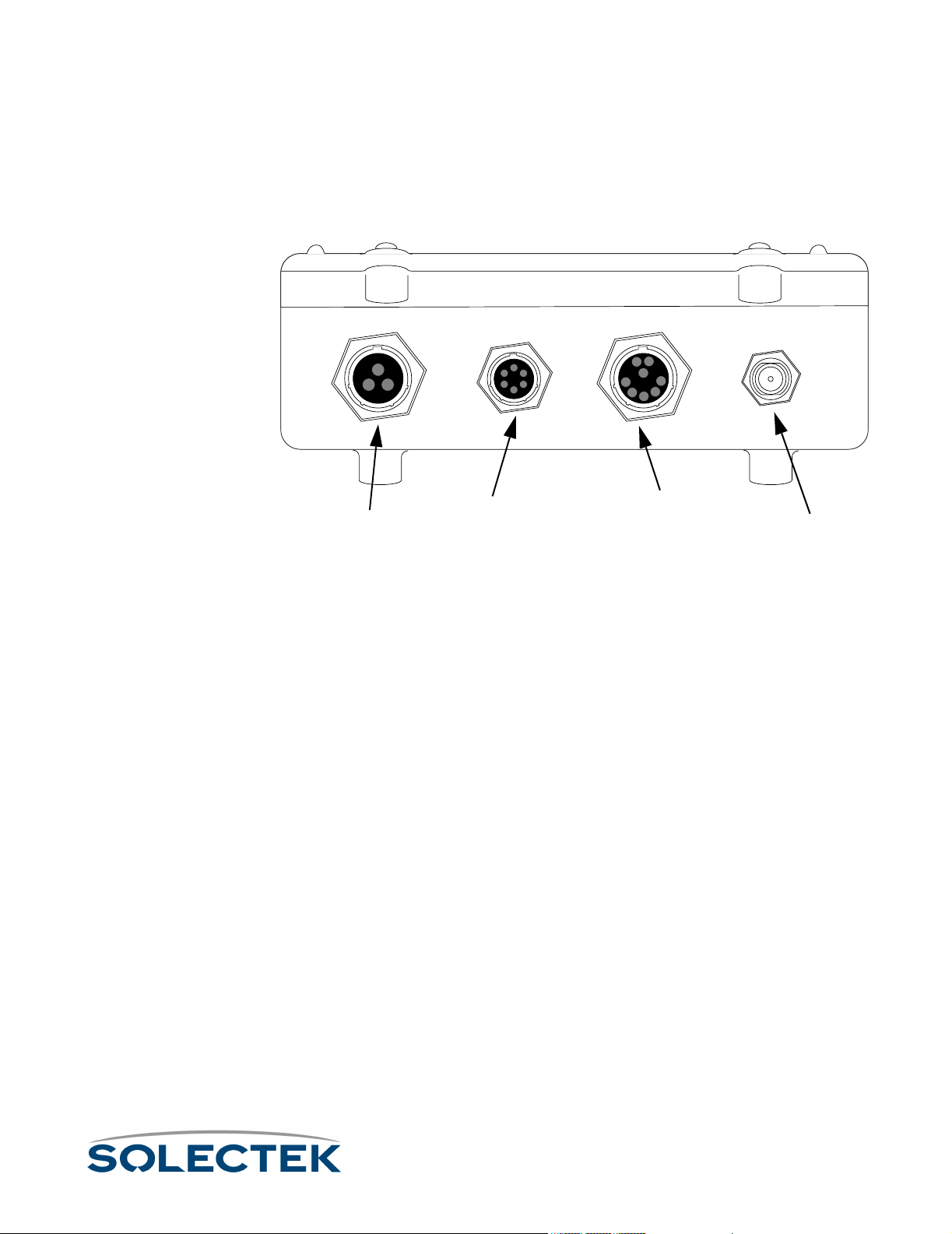
The Skyway wireless bridge/router includes the following components:
• a ruggedized, weatherproof casing
• four connectors:
Administration
Administration
Power
Power
PowerPower
AdministrationAdministration
Console
Console
ConsoleConsole
Ethernet
Ethernet
EthernetEthernet
10 /100 Base-TX (shown)
10 /100 Base-TX (shown)
10 /100 Base-TX (shown)10 /100 Base-TX (shown)
or 100 Base-FX
or 100 Base-FX
or 100 Base-FXor 100 Base-FX
RF Antenna
RF Antenna
RF Antenna RF Antenna
Bottom View of the SkyWay Bridge/Router
Bottom View of the SkyWay Bridge/Router
Bottom View of the SkyWay Bridge/RouterBottom View of the SkyWay Bridge/Router
Power. The power receptacle (3 pin) accommodates the DC power cable supplied
with the SkyWay; it accepts 48 V DC. To apply or remove power, connect or disconnect the power cord to or from the AC/DC power converter.
Administration Console. The EIA/TIA-422 console connector (6 pin) accommo-
dates the console cable supplied with the SkyWay. The opposite end of the cable has a
DB-9 RS-422 connector that connects to a supplied RS-422 to RS 232 converter that
you connect to the RS-232 port of your PC or terminal. You can also connect the converter to your modem. For a diagram, see “Accessing the SkyWay Bridge/Router” on
page 22.
Ethernet Port. The Data/Ethernet connector accommodates one of the following
two cables depending on the SkyWay model you ordered:
• 10/100 Base-TX (twisted pair) (8 pin)
• 100 Base-FX (fiberoptic) (2 pin)
The opposite end of either cable connects to your LAN or WAN server’s Ethernet
port.
RF. The RF connector (“N” type female) accommodates an LMR-400 RF coaxial cable
that connects to an RF antenna. For more information about antennas, see “Appendix
K: Skyway Antennas” on page 213.
For pinout information, see “Appendix C: Interface Specifications and Pinouts” on
page 181.
11
Page 38

Specifications
For a list of SkyWay Bridge/Router specifications, see “Appendix D: Detailed Product
Specifications” on page 185.
12
Page 39

Understanding the Menu Structure
Understanding the Menu Structure
The SkyWay screens are organized by function, and are hierarchically numbered. The
Run Time Main Menu is shown below:
The Configuration menu, option 1, shows you a list of 5 options. For example, 1.1
System Configuration, 1.2 Port Configuration, etc. For a complete list of the screens in
the menu tree, refer to “Appendix A: Run-time Menu Tree” on page 175, and “BIOS
M enu Tr ee S u mma r y Tab le ” on pa ge 1 79 .
For information on the Bios Application, see
Navigating Through Menus and Screens
Use the keys in the following table to navigate through the menus:
To …
To … Press This Key…
To …To …
Move down or up through menu
options
Move through list of field entries
Select an item or edit a field
Go up one menu level
Move between fields
Enter a command
Go directly to a particular screen if
you know the screen number
Press This Key…
Press This Key…Press This Key…
Down- or Up-Arrow
Right- or Left-Arrow or space bar
Enter
\ (Blackslash)
Tab, Up- or Down-Arrow
.(dot) followed by the command. (see “Dot
Commands” on page 14)
From the Main Menu, enter the screen number. From other screens where commands are
available, press
of the screen. The screen title appears above
the number. If this is the screen you want,
press Enter.
. (dot), then type the number
13
Page 40

Dot Commands
You can access commands from all non-menu screens. When they are available,
. - commands appears at the bottom of the screen. Press
mand line which lists the available commands for that screen, that is, not all commands
are available on every screen. The following table describes the commands:
. to display the com-
.H
.M
.R
.W
.A
.N
.P
.C
.G
Go to the HELP screen, which lists arrow keys
and
. commands.
Monitor Mode on or off. Monitor mode continuously refreshes the data displayed, allowing
you to see the system operating in real time.
Update screen data (refresh)
Save screen data to the database (write). This
is usually required after you make a configuration change before the change takes affect.
Add a new record to a table
Display the next record in a table.
Display the previous record in a table.
Cancel any changes made to this screen
before
before you press
beforebefore
Go to the specific table record by key value
(for example, port number).
.W
14
.Z
.F
.(dot)
Clears the statistics on the current status
screen (zero)
Flushes tables. Available for these screens:
• 2.1.3 Error Log Screen
• 2.3.4 Transparent Bridging Table
• 2.4.1.5 ARP Table
This is functionally the same as accessing the
3.3 Flush utility, which allows you to flush one
or more of the above tables at a time.
Use to go to a particular screen number. Type
. (dot), then type the screen number you
want to go to (for example, 224) and press
Enter. You cannot use this method at a menu
screen.
Page 41

Understanding the Menu Structure
How Screens Display Information
Configuration and status records are displayed in the following formats:
Screens Displaying One Record. On some screens, one row or record of the
table appears at a time (see screen 2.2.1. for an example). All of the data displayed is
from a single record in the table. The record you are looking at is indicated at the top
right of the screen (for example, Record 1 of 2 means you are looking at the
first record (row) of data in a two-record table). Press .N to see the next record, or
to see the previous record.
Scrolling Screens. Some screens display information that does not fit on one screen
(for example, the summary screens, such as 1.6 Configuration Summary). Press .N to
see the next screen, or
Common Rows. Common fields appear only on screens containing tables with many
rows. Common rows display in the 4-row space above the command line at the bottom of the screen. These rows display field data for the record at the cursor position.
For example, in screen “2.5.1 RF-DLC Base Port Status” on page 140, when the cursor points to the first row, the field data at the bottom of screen are for that record.
• As a static variable
• As a table with many rows or records
• As a table with one row or record
.P
.P for the previous screen.
Editing Fields
Fields that you can edit or configure display the current value with a blinking cursor. To
change the value, position the cursor on the field, and press
Field Types
The types of field data in a record are:
• Numeric - Enter a number within a certain range. If the number you enter is
outside the range, the field redisplays the original value and the cursor remains
on the field.
• Text - Enter alphanumeric characters up to the maximum length allowed.
• Select from a List - Enter or select values using the arrow keys or Space Bar to
scroll through the list of valid entries for that field (brackets appear around the
field value).
To finish editing the field, press Enter to accept the new value, remove the brackets,
and move to the next field.
To back out all changes, press
To save all changes, press
.C to cancel.
.w to write the changes to the database.
´.
Note Access to certain screens and fields may be restricted for certain users. See “Adding
Users and Setting Access Levels” on page 62.
15
Page 42

Saving Configuration Changes
Save any changes you make by using the .W command. This updates the database
immediately, and the screen refreshes, displaying the new values. Sometimes, however, you must reset the unit, or cycle the port for the changes to take affect (see
“Changes that Require Cycling or Resetting” on this page).
If you make changes to a screen, and try to leave it without saving, the screen warns
you “Data has been modified. Write or Cancel changes.” Press
.W or .C to remove the warning and return to the screen.
Note Sometimes the Write and Cancel commands do not appear in the list of commands (at
the bottom of screen) unless you make a change to a field.
Understanding the Configuration Database
Default configuration settings are stored in a non-volatile configuration database on the
SkyWay. When the unit is started or reset, the configuration database is loaded and
determines the runtime characteristics of each port.
The SkyWay allows you to make configuration changes to the Ethernet and RF ports
without disrupting operations. The changes are stored in the configuration database,
allowing you to change Skyway’s runtime port characteristics without resetting the unit,
by ‘cycling’ the port. This allows you to make minor changes on a port by port basis
without affecting operations on the other ports. This is very important on a base station
supporting many sub stations, where you need to avoid breaking the communications
link between the base station and any sub station.
Changes that Require Cycling or Resetting
You must cycle the port for the changes to take affect immediately if you edit any port
level configuration parameters (for example, those in the 1.2 menu tree).
To cycle the port: 1. Go to 2.2.1 Generic Port Status and Control.
2. Type 3 ( o r .N until the port number is the one you want).
3. Set the Administrative Status
Administrative Status field to Cycle.
Administrative StatusAdministrative Status
4. Ty p e .W
Cycle evacuates the port, reinstalls the driver, reads the database, and brings up the
port.
Resetting the Unit
You must reset the unit if you download an update to the SkyWay software using the
file transfer utilities, or if you change any global parameter, such as:
• enabling or disabling bridging
• enabling or disabling routing
16
Page 43

Understanding the Menu Structure
• changing the RF frequency
• changing the data rate
Caution If you are resetting the base station, all the sub station links also go down. The sub sta-
tions then go into ADP mode.
To reset the unit: 1. Go to the Main Menu.
2. Type 5 (Start Application).
3. Choose Runtime as the Application to Start
Application to Start.
Application to StartApplication to Start
4. Press .W.
This reloads the updated database containing the new configuration parameters.
17
Page 44

Bios Application
The Bios application is mainly used for diagnostic purposes and is not available through
SNMP. There are two ways to start the Bios application:
Starting the Bios
Application from
Reset
Starting the Bios
Application from
Runtime
1. When you reset the unit, a message displays asking you to press any key to start
the Bios Application before the time out occurs and Run time starts. Press any key,
which starts the Bios application and displays the Bios Login screen.
2. Enter your username and password.
3. The Bios Main Menu displays.
1. From the Runtime Main Menu, press 5 (Start Application).
2. Choose Bios Application as the Application to Start. It takes several seconds before
the “Press any key to start Bios application” message displays.
3. Press any key before the timeout occurs (or the system restarts the Runtime appli-
cation). The Bios Login screen displays.
4. Enter your username and password.
5. The Bios Main Menu displays.
Bios Main Menu
The Bios menu consists of 9 options:
Bios Main Menu
18
Bios Main Menu
1. Configuration Menu
2. Diagnostics
3. Files
4. Utilities
5. Error Log
6. User Screens
7. Reset SkyWay
8. Start Application
9. Log Off
Use arrow keys to select an item, then press ENTER; \ - Go up one level
Since many of the options here are similar to those in the Runtime application, the following table tells you where to find further information:
Page 45

Bios Application
Bios Menu Option For information, see...
1. Configuration Menu “Bios Configuration Menu” on
page 19
2. Diagnostics “ BIOS Diagnostics” on
page 104
3. Files “ File Directory” on page 111
4. Utilities
4.1 YMODEM and
4.2 XMODEM
4.3 Configuration
Database Service
4.4 Real Time Clock “ Setting the System Date and
5. Error Log “ Checking the Error Log” on
6. User Screens “ Adding Users and Setting
The remaining options are:
Bios Menu Option Function
7. Reset SkyWay Immediately resets the
8. Start Application Starts the Runtime appli-
“ 3.1.2 YModem” on
page 114
“ Configuration Database Service” on page 21
Time” on page 64
page 130
Access Levels” on page 62
unit.
cation.
9. Log Off Exits SkyWay
Bios Configuration Menu
The Configuration options are:
Option See Runtime Screen
System None (see “Bios System
Configuration” on this
page)
19
Page 46

Option See Runtime Screen
Serial Port “1.2.1.1 Serial Port Con-
figuration” on page 24
Serial Transceiver “1.2.1.2 Serial Transceiver
Configuration” on
page 25
Ethernet Port “1.2.2.1 Ethernet Port
Configuration” on
page 83
Ethernet Transceiver “1.2.2.2 Ethernet Trans-
ceiver Configuration” on
page 85
Bios System Configuration
Use this screen to check your system configuration and to change the Bios Timeout
default.
1.1. System
Product Code : SkyWay Bridge
Board Revision : Version 1
Software Version : Bios Version 00.31A-T
Media Type : Twisted-pair
RF Power Type : Low Power
VCO Type : Package
SDRAM Size : 16 Megabytes
Flash Size : 4 Megabytes
Serial Number : 0
Country Code : U.S.
MAC Address : 00:c0:61:00:00:00
Bios Timeout (sec) : 5
20
\ - return to menu . - commands TAB - next available field ENTER - edit
The Bios Timeout sets the default number of seconds the system waits to allow you to
press a key to load the Bios Application. The range is 5 to 120 seconds.
Page 47

Bios Application
Configuration Database Service
This utility allows you to work with the Bios and Runtime configuration databases.
4.3. Configuration Database Service
Bios DB Action : None
Runtime DB Action: None
Bios DB Status : Present
Runtime DB Status: Present
Saved DB Status : Absent
\ - return to menu . - commands TAB - next available field ENTER - edit
Field Name MIB Default Setting
Bios DB Action ••••None
None • Initialize
NoneNone
Select Initialize to clear out the present Bios configuration database and restore the
default shipped configuration.
Runtime DB Action ••••None
None
NoneNone
•Initialize
•Save
•Restore
Select Initialize to clear out the present Runtime configuration database and load the
default factory configuration database. Select Save to save the current Runtime configuration database as the new default Runtime configuration database. Select
Restore to clear out the present Runtime configuration database and load the Saved
Runtime configuration database.
Bios DB Status ••••Present
Present •Absent
PresentPresent
A status field which tells you whether the Bios database is loaded.
Runtime DB Status ••••Present
Present • Absent
PresentPresent
A status field which tells you whether the Runtime database is loaded.
Saved DB Status ••••Absent
Absent •Present
AbsentAbsent
A status field which tells you whether a Saved database is loaded.
21
Page 48
Accessing the SkyWay Bridge/Router
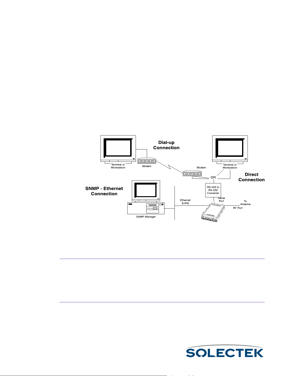
There are three ways to access the SkyWay Bridge/Router:
• Direct Connection.
Direct Connection. Use a terminal that is directly connected to the unit's
Direct Connection.Direct Connection.
RS-422 port. This is called the local console, and it allows you to directly
access all of the Skyway’s configuration and management screens.
• Dial-up Connection.
Dial-up Connection. Use a dial-up modem attached to the SkyWay to access
Dial-up Connection.Dial-up Connection.
the local console. Functionally, it is the same as being directly connected.
•SNMP Connection.
SNMP Connection. Use an SNMP Manager to access most of the Skyway’s
SNMP Connection.SNMP Connection.
configuration screens. The SNMP Manager accesses the SkyWay over Ethernet or a SkyWay’s RF link with another SkyWay. For Configuration and Status
screens not accessible via SNMP, see “Appendix A: Run-time Menu Tree” on
page 175.
The following diagram shows these three methods:
To configure a
modem attached to
the SkyWay
To c o nf i g u r e t h e
Terminal for dialing
to the SkyWay
22
For more information about connecting the SkyWay to a console, see “Connecting to
the Administration Console” on page 51.
Modem Settings for Dial-up Connection
Set the modem to Auto Answer.
1.
2. Set the modem’s RS-232 port speed to Fixed. It cannot follow the connection
speed, because SkyWay’s serial port is a manually configurable fixed speed.
3. Set DTR to High to Always On. This is necessary for some modems.
1. Set the terminal to type VT-100.
2. Set the baud rate to the SkyWay-configured baud rate (default is 115200 bps). To
change the SkyWay’s baud rate, go to “1.2.1.1 Serial Port Configuration” on
page 24.
Page 49

Accessing the SkyWay Bridge/Router
3. Set the terminal to 8-bits, No Parity, 1 Stop Bit.
4. Dial the modem attached to the SkyWay.
Example AT
Commands
You may need to write a command line to configure your modem for use with the
SkyWay. The example command line below is listed for your convenience and is not
configured through a screen on the SkyWay. The following is an example of the AT
command settings for a USRobotics V.Everything modem attached to the SkyWay.
The AT command line reads: ATQ1&A0&B1&D0&F0&H0&R1S0=1&W
Where…
Where… Means…
Where…Where…
Q1 Suppress result codes
&A0 Don’t display ARQ result codes
&B1 Fixed DTE speed
&D0 Ignore DTR
&F0 Load no flow control template settings
&H0 Disable transmit data flow control
&R1 Ignore RTS
S0=1 Answer on first ring
&W Write to NVRAM
Means…
Means…Means…
The above command line disables any flow control, fixes the speed of the serial port,
and disables any response codes back to the SkyWay unit. Make adjustments or additions to these settings based on your local configuration.
These change the default configuration; however, the modem should then boot from
the NVRAM settings.
Configuring the Serial Port and Serial Transceiver
Go to the 1.2.1.1 Serial Port Configuration, or 1.2.1.2 Serial Transceiver Configuration
screen.
23
Page 50

1.2.1.1 Serial Port Configuration
1.2.1.1 Serial Port Configuration
Port Number : 1
Configuration Status : On-line
Buffers : 80
Transmit Buffers : 12
Receive Buffers : 12
Maximum Frame Size : 512
\ - return to menu . - commands TAB - next available field ENTER - edit
Field Name MIB Default Setting
Port Number [swSerialPortIndex] 1
The serial port number is 1.
Configuration Status [swSerialPortConfigSta-
On-line
tus]
Whether this port configuration initializes upon reset. On-line means the port
comes up as a serial port when the unit is reset; Off-line means the port does not
initialize upon reset.
Buffers [swSerialPortMaxBuffers] 80
Serial port buffers.
Transmit Buffers [swSerialPortTransDesc] 16
Serial port transmit buffers.
Receive Buffers [swSerialPortRecvDesc] 16
Serial port receive buffers.
Maximum Frame Size [swSerialPortMaxFrame-
512
Size]
Largest frame that can be transmitted vial the serial port
24
Page 51

Accessing the SkyWay Bridge/Router
1.2.1.2 Serial Transceiver Configuration
1.2.1.2 Serial Transceiver Configuration
Port Number : 1
Baud Rate : 115200
Data Bits : 8
Parity : NONE
Stop Bits : One
\ - return to menu . - commands TAB - next available field ENTER - edit
Field Name MIB Default Setting
Port Number [swSerialPortIndex] 1
The serial port number is 1.
Baud Rate [swSerialPortBaudRate] 115200
The baud rate of the local serial port.
Data Bits [swSerialPortDataBits] 8
The number of data bits for the serial port.
Parity [swSerialPortParity] NONE
The parity setting for the serial port.
Stop Bits [swSerialPortStopBits] One
The number of stop bits for the serial port.
25
Page 52

26
Page 53

Chapter 3:
Chapter 3:
Chapter 3: Chapter 3: Preparing for Installation
Preparing for Installation
Preparing for InstallationPreparing for Installation
Since the Skyway bridge/router is a ruggedized device installed outside the building,
Solectek recommends spending some time planning the installation and testing the
configuration before permanently mounting the units.
This chapter contains the following information:
Before Installing ................................................................ 28
Safety Considerations ....................................................... 29
General Safety Guidelines ........................................... 29
Electrical Safety Guidelines .......................................... 29
Pre-installation Procedures................................................ 30
Site Considerations..................................................... 30
Bench Test ................................................................. 32
27
Page 54

Before Installing
To complete your SkyWay installation, you need the following items:
• A pair of cellular telephones or walkie-talkies, so installers can communicate
• (Optional: Needed only if you find it absolutely necessary to cut the indoor
• VT-100 console or a workstation with VT-100 emulation capability and termi-
• (Optional) a modem, if you want to operate the SkyWay Bridge/Router
when aligning SkyWay antennas during the installation process
connectors off to accommodate pulling the cable through conduit):
• Ethernet cable: an RJ-45 cable crimper to terminate the RJ-45 connection
to the Ethernet LAN during the installation process
• Serial cable: a small screwdriver to disassemble the DB-9 case, a pin
removal extractor tool or a replacement DB-9 jack
• Power cable: a soldering iron
For pin-out information, see “Appendix C: Interface Specifications and Pinouts”
on page 181.
nal emulation software such as Hyperterm™ or Procomm™ to configure the
SkyWay Bridge/Router
through a dial-up connection
• 13 mm hex socket wrench for mounting bracket
• Slotted screw driver for mounting clamps
28
Page 55

Safety Considerations
Safety Considerations
The following sections provide guidelines to ensure your safety when installing and
working with the SkyWay Bridge/Router.
General Safety Guidelines
Observe the following guidelines to ensure general safety:
• Keep tools away from walk areas where you and others could trip over them.
• Do not wear loose clothing that could get caught in the chassis mounting hardware. Fasten your tie or scarf and roll up your sleeves.
• Wear safety glasses when working under any conditions that might be hazardous to your eyes.
• Do not perform any action that creates a potential hazard to people or makes
the equipment unsafe.
Electrical Safety Guidelines
Observe the following electrical guidelines when working on the SkyWay Bridge/
Router.
• Do not work on the system or connect or disconnect cables under these conditions:
• during a thunderstorm
• when wearing a wool sweater or other heavy wool clothing
• when power is applied
• Do not touch the SkyWay power supply when the power cord is connected.
Because the SkyWay Bridge/Router does not have a power switch, line voltages are present within the power supply when the power cord is connected
to the Bridge/Router.
• The SkyWay’s Bridge/Router relies on the building’s installation for short-circuit
(overcurrent) protection. Make sure that a fuse or circuit breaker not larger
than 120 VAC, 15A U.S. (240 VAC, 10A international) is used on the phase
conductors (all current-carrying conductors).
• Before working on the SkyWay chassis, unplug the power cord from the AC
outlet or disconnect the fuse or circuit breaker.
• Locate the emergency power-off switch for the AC source connected to the
SkyWay Bridge/Router. If an electrical accident occurs, use this switch to turn
off power to the bridge.
• Identify possible hazards in your work area, such as moist floor, ungrounded
power extension cables, and missing safety grounds. Do not work alone if
potentially hazardous conditions exist.
29
Page 56

Pre-installation Procedures
Planning and feasibility studies are critical to successfully integrate the SkyWay Bridge/
Router with your network. There are additional factors, for example, Radio Line of
Sight and overall RF environmental issues, which must be taken into account for wireless connectivity.
Site Considerations
Deploying a successful network requires feasibility studies and careful planning, particularly for wireless connectivity solutions where additional factors must be considered.
Radio Line of Sight and overall RF environment must be assessed and documented to
assist in determining the initial installation as well as providing a baseline for future RF
environmental measurements when suspected local RF environment changes occur.
Step One: Assess Your Network Requirements
Solectek recommends the following steps in determining the feasibility of a wireless
internetworking solution using Solectek wireless bridges and routers:
• Identify, list and classify the data resource centers by type and number of users
• Layout the topology of voice, data and video networks indicating bandwidth
requirements, protocols, and media of each network segment.
• Plan and layout the IP addressing scheme for IP and IPX networks
• Ensure all protocols deployed in the planned network, including planned wireless segments, can be encapsulated in Ethernet frames 802.1d, 802.3, and
802.2.
• Identify protocols and network segments which will require encapsulation in IP
packets and consequent routing.
Step Two: Map Wireless Network Pre-Design
You then provide details about locations to be connected, for example, building-tobuilding, or server-to-ISP.
• Identify and mark the locations of the main nodes of the network on a geographical map of the region. Attach full street addresses and building characteristics to each location.
• Gather site coordinates (latitude and longitude) for each location
• Use the site coordinates to determine optimal geographical layout of desired
link paths for wireless network segments, and complete the wireless network
geographical map.
• Determine minimum antenna height requirement for each location, which
guarantees that in each link’s path, at least 60% of Fresnel zone is unobstructed.
30
Page 57

Pre-installation Procedures
Step Three: Perform a Site Survey
In this step, you assess the Line of Sight and RF environmental factors.
• Check for the existence of competing RF signals, using a spectrum analyzer.
• Detect and measure the potential sources of interference in selected RF bands
for each site
• Mark the direction and nature of detected RF interference on the wireless network map (created in step two).
• Determine the height of obstacles (trees, buildings, highways) in each link’s
path.
Step Four: Finalize the Design
The final step includes adjusting your plan and selecting equipment.
• Adopt changes in the network layout to overcome RF interference, and to
guarantee the minimum required bandwidth for each link.
• Adjust antenna height requirements based on identified obstacles in the site
survey.
• Select the antenna types for each site, based on the link distance and minimum
antenna co-location requirements.
• Select an RF channel and antenna polarity plan for each link.
• Select cable types and lengths.
31
Page 58

Bench Test
Solectek strongly recommends using the Bench Test for testing the SkyWay Bridge/
Router prior to installing it in its permanent location. The test provides a means to
install and configure the equipment to your requirements. It allows you to become
familiar with the equipment’s operation and capabilities in a user-friendly environment.
Installers who bench test all equipment and configurations have a significantly higher
success rate during field installation than those who skip the test.
The following are required for the bench test:
• At least 2 SkyWay units
• SkyWay power cable and AC/DC converter
• Console cable and RS-422 to RD-232 converter
• Test antenna for each SkyWay RF port
• Two terminals or workstations with VT-100 emulation capability (one for each
Skyway), or one workstation with two RS-232 ports to accommodate two
SkyWays (see “Step One: Connecting Components” on page 33).
Minimum Configuration Settings and Factory Defaults for Bench Test
•RF frequency
RF frequency: Use the most efficient RF frequency for your SkyWay as deter-
RF frequencyRF frequency
mined during the site survey.
• Tap Value
Tap Value: During installation, the installer decides on an appropriate tap value
Ta p V al ueTa p V al ue
for your SkyWay so that there is no interference with other SkyWay traffic.
•Mode
Mode: Designate one SkyWay as the base station, and the other as the sub
ModeMode
station.
32
Page 59
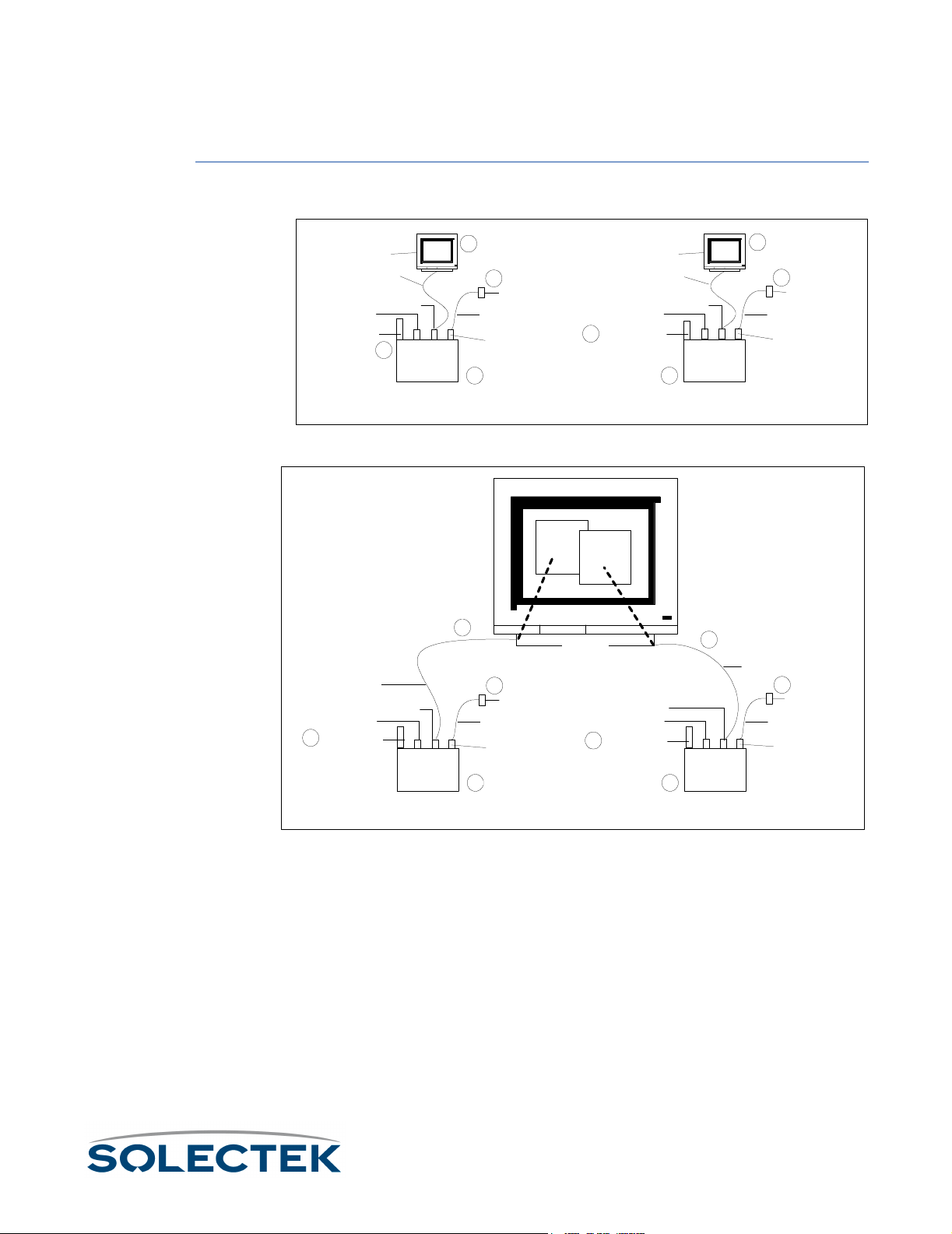
Bench Test
Performing the Bench Test
Step One:
Connecting
Components
Use the following to connect the components in a bench test environment. There are
two possible scenarios:
Terminal or PC
Console cable
Ethernet Port
Test Antenna
Console cable
Ethernet Port
4
test antenna
Serial port
4
SkyWay 1
3
2
AC/DC converter
Power cable
DC Power
connector
1 1
Terminal or PC
Ethernet Port
4
Test Antenna
Console cable
Serial port
SkyWay 2
Scenario 1: Two SkyWay units connected to two terminals or PCs
COM1
COM2
Serial port
SkyWay 1
3
PC running
Hyperterm
2
AC/DC converter
Power cable
DC Power
connector
1 1
Ethernet Port
4
test antenna
Serial port
3
SkyWay 2
3
2
AC/DC converter
Power cable
DC Power
connector
Console cable
2
AC/DC converter
Power cable
DC Power
connector
Scenario 2: Two SkyWay units Connected to One PC
1. Position two SkyWays side by side.
2. Connect the DC power cables to the rear panels of the SkyWays. Connect the
other ends to two AC/DC converters. Plug in the converters to power.
3. Connect two console cable connectors to the rear panels of the SkyWays. Con-
nect the opposite ends (RS-422/RS-232 converters) to the COM1 ports of two
computer workstations or to the COM1 and COM2 ports on one computer
workstation.
4. Connect the test antenna to the RF ports of the SkyWays.
33
Page 60

Step Two:
Preparing the
Computer
Workstation for the
Bench Test
Use the following steps to set up the administration console that you will use to monitor and configure the test. The following shows an example using a PC with Hyperterm set for VT-100 terminal emulation.
1
2
Start a Hyperterminal Session:
Under Windows, click Start,
Accessories, Hyperterminal.
Set up COM 1:
In Connection Description:
Select an icon
Enter a name - for example:
COM1 - SkyWay 1;
COM2 - SkyWay 2
3
4
6
Connect to COM1:
In Connect To Dialog, at
Connect Using:
Select COM1
Set up COM1 properties:
In COM1 Properties: choose
these port settings:
BPS - 115200
Data bits - 8
Parity - none
Stop bit - 1
Flow control - none
Set VT-100 Emulation:
5
In Hyperterminal, click File-Properties--settings tab
Choose VT-100 Emulation
Click ASCII button
Uncheck Wrap lines.... box.
Repeat Steps 1 - 5 for the
second SkyWay:
lf you are using only one PC, set
up COM 2 port on the PC.
If you are using two terminals or
PCs, set up the other terminal or
COM 1 on the other PC.
34
DONE
Page 61

Bench Test
1. Start Hyperterminal on one of the workstations. (For Windows, go to Start|Acces-
sories|Hyperterminal.)
2. In the Connection Description
3. In the Connect To
4. In the COM 1 Properties
Connection Description box, select a name and icon.
Connection DescriptionConnection Description
Connect To box, at “Connect using”, select COM 1.
Connect ToConnect To
COM 1 Properties box, select the following port settings:
COM 1 PropertiesCOM 1 Properties
• Bits per second: 115200
• Data bits: 8
• Parity: None
• Stop: 1
• Flow control: None
5. From the Hyperterminal top menu, select File|Properties|Settings tab, and do the
following:
• From the Emulation menu, select “VT-100”.
• Type the ASCII setup button, and clear the wrap lines
wrap lines box.
wrap lineswrap lines
6. Start Hyperterminal again on the same workstation to open a new screen (if you
have connected the SkyWay to two COM ports), or start Hyperterminal on a second workstation linked to the second SkyWay. Do the following:
• In the Connection Description
• In the Connect To
Connection Description box, select a new name and icon.
Connection DescriptionConnection Description
Connect To box, at “Connect Using,” select COM 2 if you are using one
Connect ToConnect To
computer and two com ports. If you are using a second workstation, select
COM 1.
35
Page 62

Step Three:
Configuring the
Bench Test
Use the following steps to set the parameters for running the bench test.
Login to SkyWay1:
Go to the first Hyperterminal
1
blank screen (this will be the
Base station).
Press Enter to bring up the
2
SKYWAY Login Screen.
Enter "Solectek" as the
3
default for both username
and password.
System Name :
System Location :
User Name :
Password :
SkyWay
Model_xxx
Version 1.0
Solectek Corporation
Copyright 1999 - All Rights Reserved
Configure the RF Base
4
Diag Port:
At the Main Menu, type
1232 to get to this screen
Port Type=RF Base Diag
Type .W to write the
changes to the database
Configure the RF Sub
5
Diagnostic Port:
Go to screen 1.2.3.3 to set
the RF Transceiver values
based on your Site Survey.
Type .W to write the
changes to the database
Cycle the port:
6
Go to screen 2.2.1Generic Port and
Status Control
Port Number = 3
Port Type = RF-DLC Base Diagnostic
Admin St atus = Cyc le
Kt
to write the changes and
Type
cycle the port. After a few seconds,
Operation Status changes from
"Transitioning...
Up" to "Up Port."
1.2.3.2 RF Diagnostic Port Configuration
Port Number 3
Configuration Status On-line
Port Type RF-DLC Base Diagnostic Port
Max Buffers 800
Transmit Buffers 240
Receive Buffers 180
Maximum Frame Si ze 3200
Record Type Valid
1.2.3.3 RF Transceiver Configuration
RF Port RF Frequency RF Data Rate Scrambler Tap
---------- -------------------- ------------------ --------------------3 2468 2 Mbps 72
2.2.1 Generic Port Status and Control
Port Number 3
Port Type RF-DLC Base Diagnostic Port
Port Baud Rate 2 Mbps
Largest Datagram Size 1492
Physical Address 00:00:c4:1cc:91:45
Administrative Status Cycle
Operational Status Up Port
Last Status Change 0.01 seconds
Maximum Transmit Buffers 512
36
Configure the RF Sub
7
Diagnostic Port:
Go to the other
Hyperterminal blank screen
OR the other terminal.
Repeat steps 1 thru 6,
except the Port Type = RF
Sub Diagnostic Port for
each sub station unit.
Page 63

Bench Test
1. Go to the first Hyperterminal blank screen (which will serve as the “Base”).
2. Type ENTER
ENTER to bring up the Login screen.
ENTERENTER
3. Enter “Solectek” as the default for both username and password.
Note To access a screen from another non-menu screen, press . followed by the screen
number and press Enter, or return to the main menu and type the screen number. For
tips on navigating the screens, see “ Navigating Through Menus and Screens” on
page 13.
4. The Main Menu for Run Time Application will appear. Type 1232 to access the RF
Diagnostic Port Configuration screen. Make the following changes (setting may
already be correct):
• Port Type: RF-DLC Base Diagnostic Port
• RF data rate: depends on configuration setting (2, 5.5 or 11 Mbps)
Ty p e . W to apply the change. Return to the Main Menu.
5. Press 1233 to access the RF Transceiver Configuration screen. Configure the fol-
lowing values, based on information obtained during the site survey process:
•RF Frequency
• RF Data Rate
•Scrambler Tap
Ty p e .W to apply the change.
6. Press 221 to access the Generic Port Status and Control screen. Make the follow-
ing changes:
•Port Number: 3 (RF Port)
• Administrative Status: Install Port
Ty p e .W to apply the change. Make sure Administrative Status
This demonstrates that the port is active.
Administrative Status changes to Up Port.
Administrative StatusAdministrative Status
7. Go to the sub station screen. Repeat steps 2 through 6. In the RF Diagnostic Port
Configuration screen (1232; step 4), Port Type
Port. Do this for each sub station included in the bench test.
Port Type must be RF-DLC Sub Diagnostic
Port TypePort Type
37
Page 64

Step 4: Starting the
Bench Test
The two SkyWay units will now transmit information back and forth to test wireless
performance.
4.1 RF Base Radio Test
Set up the Base Station Test:
Go to SkyWay1 (the base
1
station).
2
Type
QN
to access this
screen
Test to Run = Single Fram e
Ping Pong Mode
Test Timeout = depends on
the bandwidth:
36 ms for 2 Mbs
12 ms for 5. 5 Mbs
9 ms for 11 Mbs
Type
Kª
to write the changes
RF Port Num ber 3
Test Timeout (NSL List) Milliseconds
Test To Run Single Frame Ping Pong Mode
Number of Frames or Bursts, 1 to 65535 or 0 for continuous : 0
Frame Length or Maximum Burst Size, 3 - 3200 bytes : 1530
* Note - diagnostic driver must be installed *
Set up the Sub Station Test:
Go to SkyWay2 (the sub
3
station).
Type
QO
4
5
6
7
to access this
screen
Test to Run = Single Fram e
Ping Pong Mode
Type
Kª
to write the changes
Monitor the test on the Sub:
You are sti ll at SkyW ay2 (sub).
Type
OOQ
screen
Type
statistics
Type
mode
Check the results:
Wait at least 30 seconds for an
accurate reading
Total the sum of the errors in
the errors column. The sum
should be less than 1% of the
total number of frames
received (IN).
Terminate the test:
Go to sc reen 4.1.2 and change
Test to Run = Terminate Test
Type
to access this
Kw
to clear the
Kj
to enter monitor
Kt
to write the change
4.2 RF Sub Radi o Test
* Note - diagnos tic driver must be installed *
RF Port Number 3
Test to Run Single Frame Ping Pong Mode
2.2.4 RF Port Status
Port Number 3
Port Type Sub Port Diagnost ic
Port Stat us On-line
RF data rate 2 Mbps
RF Channal 2468 Mhz
Bytes IN 0 OUT 0
Frames IN 0 OUT 0
Discards IN 0 OUT 0
Digital Phase Lock Loop
Frame Lengt h Violation
Non Octet Al igned Frame
Abort Sequence
CRC Error
Overrun
Carrier Detect Lost
Underrun
CTS Lost
Monitor the test on the Base:
Go to SkyWay1 (the base
8
station)
Repeat Step 5 - the Port Type is
9
Base Port Diag
38
Page 65

Bench Test
1. Return to the base station.
2. Access screen 4.1 Base Radio Test. Change the following:
• Test to Run: Single Frame Ping Pong Mode
This mode means that the base station sends out frames one at a time, and the
sub station returns them one at a time.
• Test Timeout to the appropriate ms selection. Select 36 ms for 2 mb, 12 ms
for 5.5 mb, and 9 ms for 11 mb.
3. Go to the sub station.
4. Access screen 4.2 (Sub Radio Test). Make the following change:
Test to Run: Single Frame Ping Pong Mode
5. Access the 224 screen (RF Port Status).
•Type .Z to zero test values.
•Type .M to monitor.
You should see the numbers incrementing in the bytes and frames row, reflecting
transmission of frames back and forth between base and sub. Wait at least 30 seconds to get an accurate reading.
Step 5: Configure
the SkyWay for
Installation
6. In the errors column on the lower left of the screen, total the sum of the errors.
The sum should be less than 1% of the total number of frames received (in the
“IN” location). To terminate the test, return to the “Base” screen, access screen
224, and change Test to Run
Test to Run to Terminate.
Te s t t o RunTe s t t o Run
7. Go to the other screen (“Base”).
8. Access the 224 screen (RF Port Status).
• Press .Z to zero the data.
• Press .M to enter monitor mode. Wait at least 30 seconds to get an accurate
reading.
• In the errors column on the lower left of the screen, total the sum of the
errors. The sum should be less than 1% of the total number of frames
received (in the “IN” location). To terminate the test, access screen 224, and
change Test to Run
To complete the configuration process, go to “Chapter 5: Configuring and Managing
SkyWay” on page 57.
Test to Run to Terminate.
Te s t t o Ru nTe s t t o Ru n
39
Page 66

40
Page 67

Chapter 4:
Chapter 4:
Chapter 4: Chapter 4: Installing Skyway
Installing Skyway
Installing SkywayInstalling Skyway
Once you have performed a successful bench test and configured the units to your satisfaction, you are ready to install and connect them.
This chapter contains the following information:
Mounting the SkyWay Unit ............................................... 42
Mounting to a Mast..................................................... 42
Mounting to a Wall ..................................................... 44
Setting Up the Antenna..................................................... 45
Grounding Skyway and the Antenna.................................. 47
Connecting Cabling .......................................................... 48
Connecting an Antenna .............................................. 49
Connecting to Power ................................................. 50
Connecting to the Administration Console..................51
Connecting to Your LAN ............................................ 53
Routing Connected Cables ......................................... 48
41
Page 68
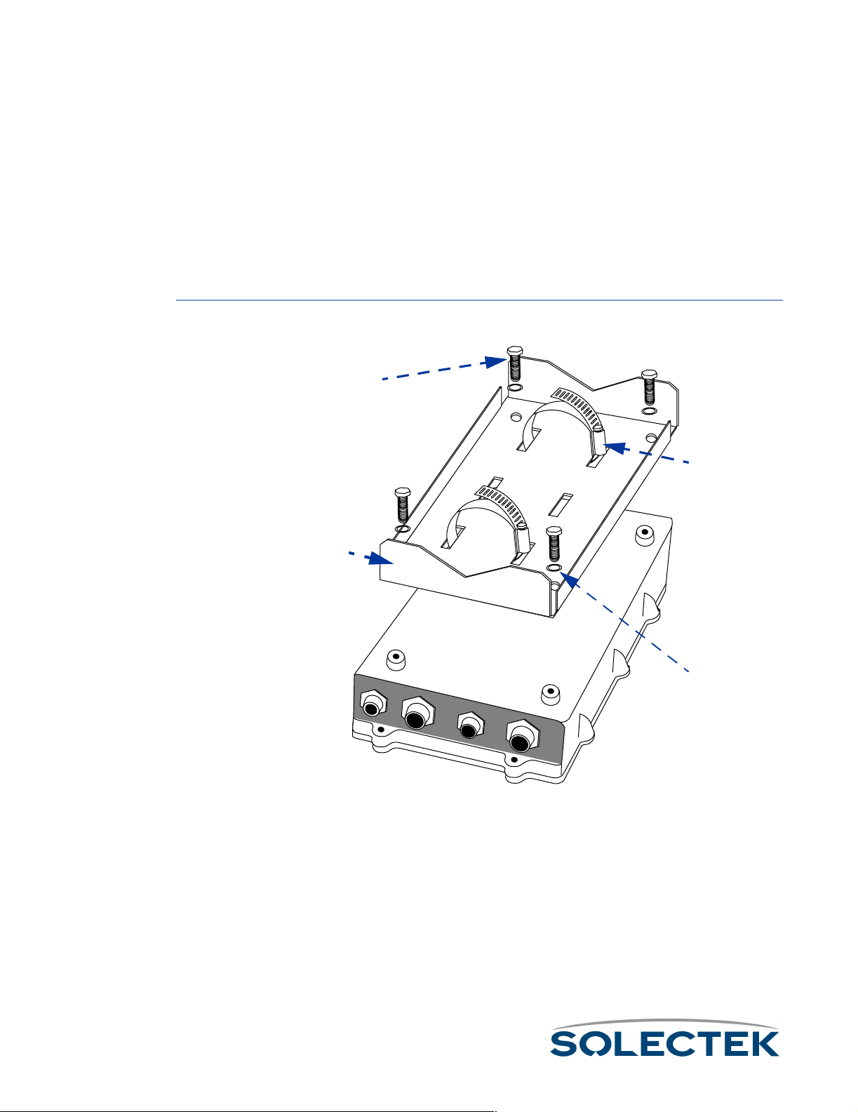
Mounting the SkyWay Unit
Mount The SkyWay Bridge/Router to an outdoor mast or wall.
Mounting to a Mast
To o l s :
To o l s :
To o l s :To o l s :
• 13 mm hex socket wrench
• Slotted screwdriver
To m o u n t t h e
SkyWay to a mast:
1. Place the mast-mounting bracket on a table with the flat side down.
P/N 1225401
P/N 1225401
P/N 1225401P/N 1225401
P/N 1225001
P/N 1225001
P/N 1225001P/N 1225001
P/N 1225501
P/N 1225501
P/N 1225501P/N 1225501
P/N 1225201
P/N 1225201
P/N 1225201P/N 1225201
Use the third central pair
of slots for seating a third
clamp if you want extra
clamp security.
42
2. Thread two clamps into the outside pair of slots on the bracket. Make sure to
thread them in the same direction.
3. Place the SkyWay face down. Place the bracket and clamp assembly over the rear
of the SkyWay so that the four mounting holes align.
4. Place one spring lock washer (P/N 1225201) on each mounting bolt.
5. Using a 13 mm hex socket wrench, tighten a bolt and washer into each hole of the
bracket to a maximum torque of 15-20 ft-lbs (to prevent stripping).
Page 69
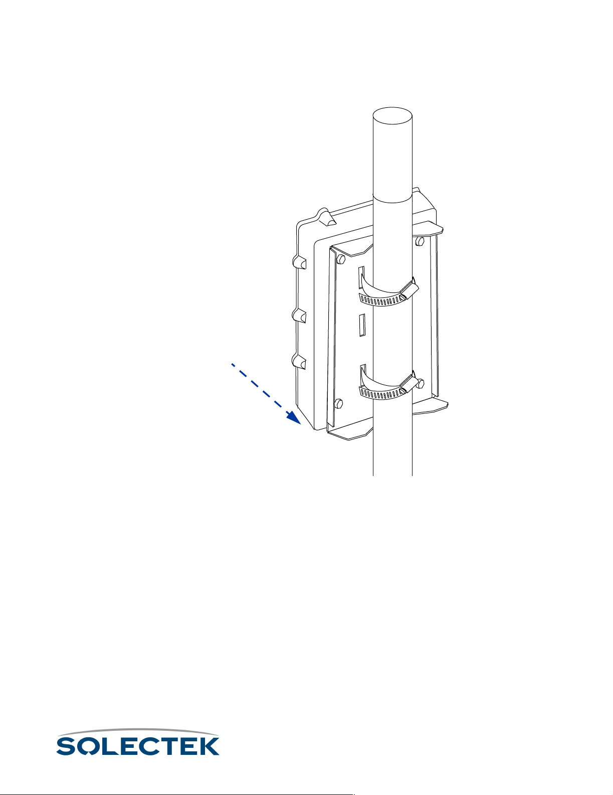
Mounting the SkyWay Unit
6. Position the bracketed SkyWay against the mast with the connectors facing down-
ward.
Connector side down
Connector side down
Connector side downConnector side down
Note: The mast should be a minimum of 1 in. (25.4 mm) outside diameter.
7. Feed the end of each clamp around the mast into the locking mechanism at the
other end. Using a slotted screwdriver or nut driver, tighten the clamp screws to a
maximum torque of 45 ± 5 in-lbs.
CAUTION: The mast to which you mount the Skyway and/or antenna should be
grounded. If the mast is not grounded, see “Grounding Skyway and the Antenna” on
page 47.
43
Page 70
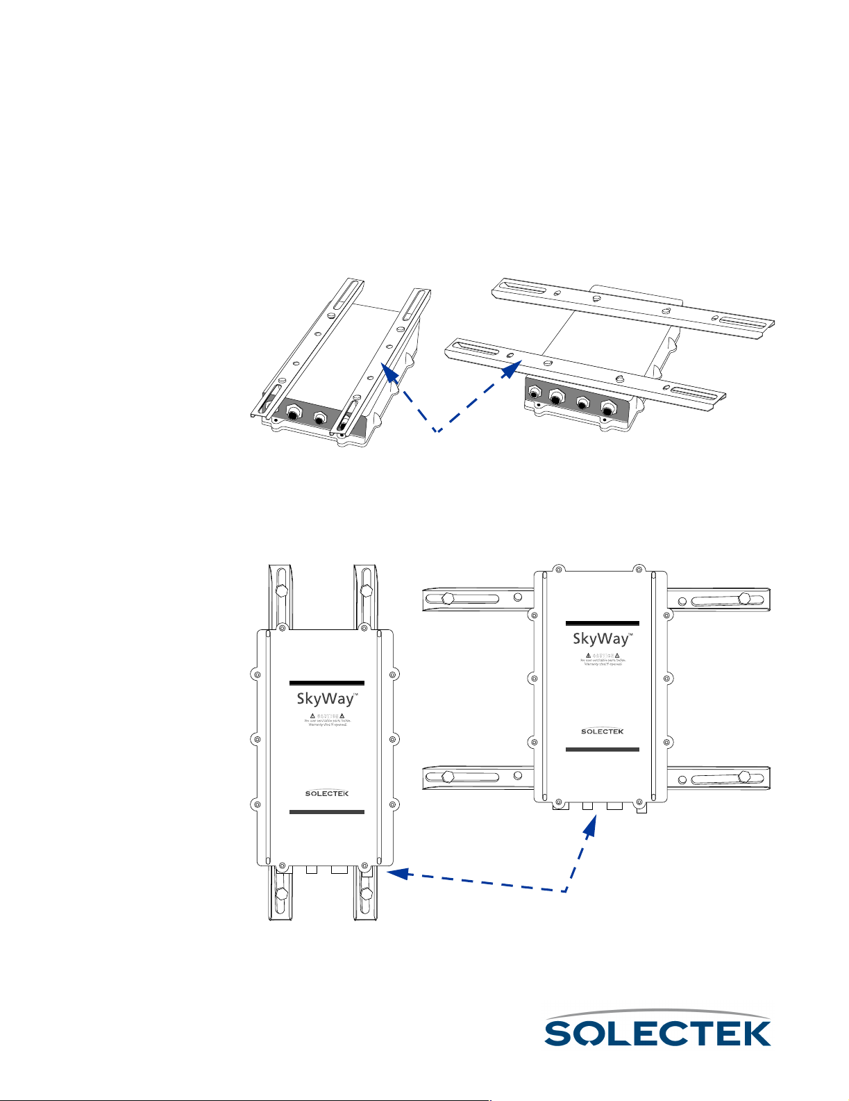
Mounting to a Wall
The wall mount kit is optional and may be purchased separately.
To o l s :
To o l s :
To o l s :To o l s :
• 13 mm wrench
1. Place the SkyWay face down.
2. Align the two brackets over the SkyWay unit’s bolt holes, either along the length or
width of the unit.
P/N 1225101
P/N 1225101
P/N 1225101P/N 1225101
3. Insert bolts and tighten with a 13 mm wrench.
Note: The bolts can be found in the Mast Kit, which is always shipped with SkyWay.
4. Fasten the SkyWay to the wall using the slider slots and bolts (not supplied), making
sure the SkyWay’s connectors face downward.
www.solectek.com
www.solectek.com
Connector side down
Connector side down
Connector side downConnector side down
44
CAUTION: The surface to which you mount the Skyway and/or antenna should be
grounded. If the surface is not grounded, see “Grounding Skyway and the Antenna” on
page 47.
Page 71

Setting Up the Antenna
Setting Up the Antenna
Skyway requires an RF antenna to receive and transmit signal effectively.
Selecting the Antenna
Solectek supplies one of several different antennas, including both sectoral and omni
models. Solectek’s systems engineers will assist you with antenna selection, taking into
account factors such as usage (point-to-point or multi-point), distance to substations,
and interference from nearby antennas.
Apart from the two omnidirectional antennas (7002301 6 dBi and 7002401 11 dBi), all
Solectek antennas are designed to be used as bridge antennas between two networks
or for point-to-point communications in the ISM band (2.4 GHz) only.
Before You Mount the Antenna
Follow these guidelines before and during installation of the SkyWay antennas:
1. Avoid reflective environments:
Avoid reflective environments: Where possible, avoid mounting antennas in a
Avoid reflective environments: Avoid reflective environments:
“reflective environment” (i.e., near objects that can reflect radio energy back to the
antenna). Signal reflections from nearby objects are seen as noise by radio transceivers, and can adversely affect the range or quality of your wireless link. Examples of such objects include the following:
• Trees or bushes
•Buildings
• Air conditioning units and ductwork
•Other radio antennas
• Building structures made of any material such as steel, brick, or wood
• Construction vehicles and equipment
2. Follow precise and safe handling procedures:
Follow precise and safe handling procedures:
Follow precise and safe handling procedures:Follow precise and safe handling procedures:
• Do not perform antenna installation by yourself. Some antennas are large and
hard to handle, especially when changing polarity or performing the final
mounting on the mast. You need a second person to align the antenna, so try
to schedule as much antenna work as possible when at least two workers are
available.
• Use a bubble level (carpenter’s level) to make sure all antennas are level with
the horizon. See Appendix K for details related to specific antennas. For antennas mounted to the wall, you may need additional spacers or washers to
obtain a level installation.
45
Page 72

3. Mount antennas securely:
Mount antennas securely: A small movement of the antenna caused by an insecure
Mount antennas securely: Mount antennas securely:
mount or weak mast results in a huge sweep at the other end of the link miles
away.
• Make sure the antenna is bolted securely to the mast.
• Always use appropriate guy wires (see your local building codes for recommendations and requirements).
• Weight non-penetrating roof mounts securely with concrete blocks or other
ballast.
4. Handle the antenna RF cable carefully:
Handle the antenna RF cable carefully: Maintain a 12-inch bend radius if possible.
Handle the antenna RF cable carefully: Handle the antenna RF cable carefully:
Do not walk on or kink the cable. A kinked cable causes severe signal attenuation,
and can cause the link to fail.
Mounting the Antenna
Connect one of the available antennas to the mast using the appropriate clamping or
bolting apparatus. For more information, see “Appendix K: Skyway Antennas” on
page 213.
46
Page 73

Grounding Skyway and the Antenna
Grounding Skyway and the Antenna
Warning: Ungrounded or improperly grounded antennas constitute a hazard to personnel and
Ungrounded or improperly grounded antennas constitute a hazard to personnel and
Ungrounded or improperly grounded antennas constitute a hazard to personnel and Ungrounded or improperly grounded antennas constitute a hazard to personnel and
equipment. A lightning strike on or near an improperly grounded antenna can cause
equipment. A lightning strike on or near an improperly grounded antenna can cause
equipment. A lightning strike on or near an improperly grounded antenna can cause equipment. A lightning strike on or near an improperly grounded antenna can cause
severe injury or death as well as equipment destruction. Any Solectek equipment
severe injury or death as well as equipment destruction. Any Solectek equipment
severe injury or death as well as equipment destruction. Any Solectek equipment severe injury or death as well as equipment destruction. Any Solectek equipment
damaged by lightning is considered to have been damaged by an Act of God, and is not
damaged by lightning is considered to have been damaged by an Act of God, and is not
damaged by lightning is considered to have been damaged by an Act of God, and is not damaged by lightning is considered to have been damaged by an Act of God, and is not
covered under warranty.
covered under warranty.
covered under warranty.covered under warranty.
Solectek antennas (2.4 GHz) and the SkyWay Bridge/Router do not require additional
grounding when mounted on antenna masts that are properly grounded per local electrical and building codes.
Supply grounding if the SkyWay and its antenna are mounted on a non-penetrating
roof mount, a wall, or an ungrounded wooden mast. In these cases, attach one end of
a bond wire to one of the bolts on the SkyWay bracket. Attach the other end to
another mast (properly grounded), a building ground, or an NEC ground.
47
Page 74

Connecting Cabling
The SkyWay connects to the antenna by means of a LMR-400 RF cable.
The SkyWay connects to power and to the terminal, terminal emulator or LAN by
means of three cables:
•power
•console
• data (Ethernet copper or fiber)
The three cables route into the building.
Routing Connected Cables
Before you begin connecting the SkyWay, consider where the cables should be routed.
within the building. SkyWay’s design enables you to route each cable to its most logical/convenient location. These locations may not be in the same room or even on the
same floor. For example, it may make the most sense to route the power to a utility
room on the top floor, the console to a secured room on the second floor, and the
Ethernet to your LAN room on the first floor:
SkyWay
SkyWay
SkyWaySkyWay
mount
mount
mountmount
Utility Room for Power
Utility Room for Power
Utility Room for PowerUtility Room for Power
www.solectek.com
48
Secured Room for Console
Secured Room for Console
Secured Room for ConsoleSecured Room for Console
LAN
LAN
LANLAN
room
room
roomroom
The length of the cables you ordered determines the maximum distance for each
connection.Be sure to secure the cables to the mast at intervals to protect the cables
and the connection.
Page 75
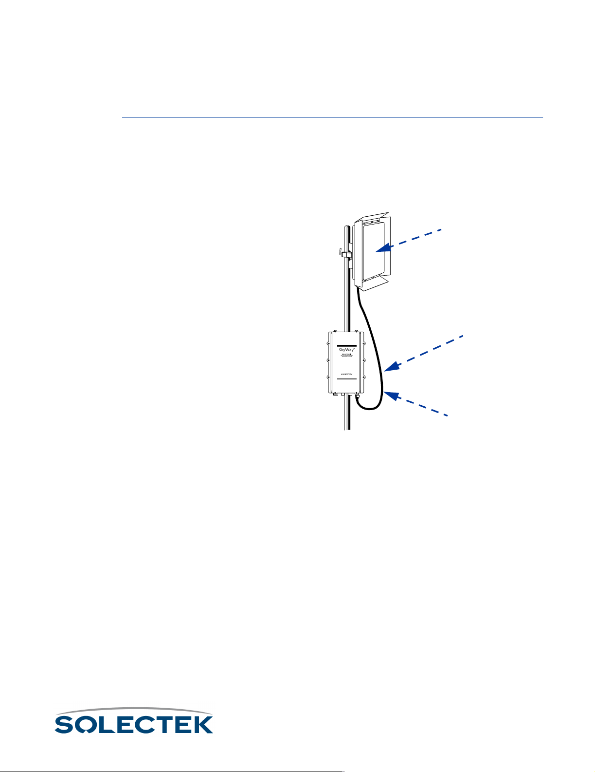
Connecting Cabling
Connecting an Antenna
The LMR-400 RF cable connects the SkyWay with the antenna above it on the mast.
To connect an RF
cable:
1. Making sure the threads are properly aligned, tighten the cable’s connector bolt
snugly over the SkyWay’s RF connector port using a 13/16 in wrench. Handtighten another 1/4 turn to lock it in place.
2. Similarly connect the other end of the RF cable to the antenna’s connector.
Note: Allow sufficient slack in the cable for a maximum turning radius of 1 ft.
Antenna
Antenna
AntennaAntenna
Slack for 1 ft turning radius
Slack for 1 ft turning radius
Slack for 1 ft turning radiusSlack for 1 ft turning radius
www.solectek.com
LMR-400 cable
LMR-400 cable
LMR-400 cableLMR-400 cable
3. Seal the connections to both the antenna and the SkyWay with “Coax Seal”
(P/N 10702) to prevent water entry.
49
Page 76

Connecting to Power
SkyWay requires DC power to operate. Solectek supplies an AC-to-DC converter
and a weather-rated DC power cable.
To c o nn e c t S k yW a y
to power:
1. Connect the power cable’s 3-pin connector to the SkyWay power port. Plug in
and lock clockwise.
Antenna
Antenna
AntennaAntenna
www.solectek.com
Power port
Power port
Power portPower port
LMR-400 cable
LMR-400 cable
LMR-400 cableLMR-400 cable
Drip loop and
Drip loop and
Drip loop andDrip loop and
Cable slack
Cable slack
Cable slackCable slack
50
2. Connect the opposite (indoor) end to the supplied AC/DC converter.
Conduit
Conduit
Conduit Conduit
or routing
or routing
or routingor routing
exit
exit
exitexit
Cable from roof
Cable from roof
Cable from roofCable from roof
AC/DC converter
AC/DC converter
AC/DC converterAC/DC converter
AC source
AC source
AC sourceAC source
AC power cord
AC power cord
AC power cordAC power cord
Note: For extra power protection, plug the AC power cord into a UPS (200 W
minimum).
Page 77

Connecting Cabling
Connecting to the Administration Console
Use this connection to:
• make and apply configuration settings to the unit
• monitor performance
• obtain transmission statistics
Solectek supplies an RS-422 weather-rated cable and an RS-422-to-RS-232 converter
for connecting to a serial communications port on the console or modem.
Connect a terminal directly to the unit's RS-422 port to provide secure access for a single console.
Note: You can use a modem to provide remote console access to all of SkyWay’s configura-
tion features. You may also use SNMP Manager on a workstation connected to the
LAN to access most of Skyway’s configuration objects. For security reasons, however,
not all SkyWay’s features are available using SNMP.
51
Page 78

To c o nn e c t d i re c t l y
to a administration
console:
1. Connect the console cable’s 6-pin connector to the SkyWay console port. Plug in
and lock clockwise.
www.solectek.com
To c o nn e c t t o a
dedicated modem
and data line:
Drip loop and
Drip loop and
Drip loop andDrip loop and
Cable slack
Cable slack
Cable slackCable slack
Administration Console
Administration Console
Administration ConsoleAdministration Console
port
port
portport
2. Route the cable to the console, being sure to create a drip loop.
3. Connect the cable at the opposite (indoor) end of the console cable (DB-9 con-
nector) to the RS-422 converter, then to the serial communication port on the
console terminal or terminal emulator.
1. Connect and route the console cable as described above, except that you will con-
nect the cable to a modem, rather than the terminal or terminal emulator.
2. Connect a standard phone cable from the modem to the dedicated data line wall
jack. For more information on configuring the modem and accessing the SkyWay
remotely, see “Accessing the SkyWay Bridge/Router” on page 22.
52
Page 79

Connecting Cabling
Connecting to Your LAN
Connect the SkyWay to your LAN via copper or fiber optic cable.
Copper cable. The 10 Base-T/100 Base-TX (twisted pair) cable is available in 100,
200, and 300 foot lengths. This cable is terminated on the indoor side with a standard
RJ-45 connector and is intended to be connected to an Ethernet hub or switch. If a
cable length of longer than 300 feet is needed, you must order the SkyWay configured
to use a fiberoptic LAN connection. See “Fiberoptic cable” on this page for more information.
Fiberoptic cable. Fiberoptic cable is available in longer lengths. Fiberoptic cable
transmission is not affected by the noise that can affect a copper cable, because electrical transmission is converted into optical transmission. This cable is terminated on the
indoor side with a standard S/C fiberoptic connector and is intended to be connected
to a fiberoptic port on an Ethernet hub or switch.
To connect an
Ethernet cable:
1. Connect the Ethernet cable’s 8-pin connector (10 Base-T/100 Base-TX) or 2-pin
connector (100 Base-FX) to the Ethernet port. Plug in and lock clockwise.
www.solectek.com
Drip loop and
Drip loop and
Drip loop andDrip loop and
Cable slack
Cable slack
Cable slackCable slack
Ethernet port
Ethernet port
Ethernet portEthernet port
(copper or fiber)
(copper or fiber)
(copper or fiber)(copper or fiber)
2. Route the cable to the console, being sure to create a drip loop.
53
Page 80

3. Connect the opposite (indoor) end of the Ethernet cable to the appropriate Ether-
net port (RJ-45 or S/C) on your LAN hub or switch.
54
Page 81

Antenna Alignment and RF Link Verification
Antenna Alignment and RF Link Verification
Once the system is installed and the antennas are mounted, you must ensure that you
have proper antenna alignment to maximize the efficiency of your RF Links. To verify
that the original antenna placement was satisfactory to bring up the RF link before starting, use the 2.5.2 RF-DLC Sub Port Status screen (described on page 143). If not,
check the azimuth settings from your design and realign the antennas. Once you have
established a link, you can utilize the ICMP Ping Utility located on the 3.2 screen
(described on page 109) to help establish your baseline settings as viewed in the 2.5.4
RF-DLC Signal Status screen (described on page 147).
Note You will need two people for this operation.
1. At the base station configure ICMP for the IP address of the substation you are
going to align.
2. Set the payload size to “64”.
3. Set the Maximum Number of Packets to “9999999”.
4. Set Delay between Packets to “0”.
5. Set Ping Operation to “Start Ping”.
6. Press .W to initiate the process.
At the base station, monitor the 2.5.4 RF-DLC Signal Status screen. Have the other
person adjust the sub station antenna while you monitor the link for the largest SL
value and the fewest number of Time-outs.
Once you have the best values you can acquire, record these readings. Then repeat
the above steps for each sub station in the cluster.
55
Page 82

56
Page 83

Chapter 5:
Chapter 5:
Chapter 5: Chapter 5: Configuring and Managing SkyWay
Configuring and Managing SkyWay
Configuring and Managing SkyWayConfiguring and Managing SkyWay
You can access the SkyWay Bridge/Router locally or remotely for configuration and
management. The local console provides a menu-based user interface you can use to
set up all of the SkyWay’s configuration features and to run diagnostics.
This chapter gives you step-by-step procedures for configuring the SkyWay Bridge/
Router for your implementation.
This chapter contains the following information:
Setting System Configuration Parameters........................... 59
Understanding RF-DLC .................................................... 65
Configuring the Ports ........................................................ 69
Bridging ............................................................................ 88
IP Routing......................................................................... 93
Internet Control Message Protocol.................................. 102
SNMP ............................................................................ 103
Diagnostics ..................................................................... 104
File Transfer Utilities ........................................................ 112
Security .......................................................................... 123
57
Page 84

Configuring SkyWay
SkyWay configuration can be divided into this sequence:
• Configuring System, Network Management, and User parameters
• Configuring the Port Parameters, which includes the RF Link Layer
• Configuring for Bridging and Spanning Tree
• Configuring for IP Routing
For many of the parameters, you can simply accept the default values. In this Guide,
each configuration parameter is described in a table following the screen. The table
includes the field name, MIB OID, and valid configuration settings, with the default setting in bold if applicable.
Configuration Features Available
The following table provides an overview of the configuration features available from
both the Administrative Console and SNMP for each of the SkyWay’s major functions:
Function
Function Console
FunctionFunction
Console SNMP
ConsoleConsole
SNMP Comment
SNMPSNMP
Comment
CommentComment
Network Management System,
Date and Time
Network Management Security, Adding Users
Port Configuration
Configuring for
Bridging
Configuring for
Routing
Configuration
Summary
X
X Screens 1.1.1 Network Management
X X Allows you to configure the serial
X X Allows you to configure bridging and
X X Allows you to enable and configure IP
X X Allows you to obtain a summary of
X
Allows you to configure the network
management system, date and time.
Security and 1.1.3 User Access Configuration Menu are not accessible via
SNMP.
port, Ethernet port, RF ports, and
manually accept sub stations.
spanning tree operations.
routing
system configuration, bridge configuration, and router configuration.
58
Page 85

Setting System Configuration Parameters
Setting System Configuration Parameters
SkyWay’s system parameters fall into four main areas:
•Network Management Security
• Network Management System
• User Access
• General Parameters
Setting Network Management Security Parameters
Use screen 1.1.1 to set up security parameters for network management. To access
this screen, you must have an access level of Super. This screen is not accessible via
SNMP.
1.1.1 Network Management Security Configuration
1.1.1. Network Management Security Configuration
Network Management Configuration:
-------------------------------- Read Community Name : public
Write Community Name :
Trap Community Name :
Enable Traps : No
Authentication Traps : No
NMS IP Address 1 : 000.000.000.000
NMS IP Address 2 : 000.000.000.000
Trap Destination IP Address 1 : 000.000.000.000
Trap Destination IP Address 2 : 000.000.000.000
\ - return to menu . - commands TAB - next available field ENTER - edit
The following table lists the field name and settings (there are no MIB OIDs for this
screen):
Field Name
Settings (default in
bold)
Read Community Name public
The read-only community name of the SkyWay agent. Must match community
name configured on the Network Management Station (NMS).
Write Community Name
The read-write community name of the SkyWay agent. Must match community
name configured on the NMS.
59
Page 86

Field Name
Trap Community Name
The trap community name of the SkyWay agent. If you set Enable Traps to Yes and
the NMS expects SNMP traps with community name, this field must match community name configured on the NMS.
Settings (default in
bold)
Enable Traps ••••No
Set to Yes to enable SkyWay to log and transmit SNMP traps. Set a Trap Destination
Address to send traps to the NMS.
Authentication Traps No
Set to Yes to cause a trap when an SNMP packet is received with an incorrect community name.
NMS IP Address 1
The IP address of the first NMS. This address setting is optional when using a NMS.
This provides an extra layer of security by forcing the IP addresses to match.
NMS IP Address 2
The IP address of the second Network Management station. This address setting is
optional when using a NMS. This provides an extra layer of security by forcing the
IP addresses to match.
Trap Destination IP
Address 1
The IP address of the first NMS to receive SkyWay SNMP traps. Enable Traps must
be set to Yes.
No
NoNo
•Yes
60
Trap Destination IP
Address 2
The IP address of the second NMS to receive SkyWay SNMP traps. Enable Traps
must be set to Yes.
Page 87

Setting System Configuration Parameters
Setting Network Management System Parameters
Use screen 1.1.2 to set up the system parameters for network management.
1.1.2 Network Management System Configuration
System Description : Solectek Corporation SkyWay
System Contact :
System Name :
System Location :
1.1.2. Network Management System Configuration
\ - return to menu . - commands TAB - next available field ENTER - edit
Field Name MIB
Settings (default in
bold)
System Description sysDescr Solectek Corporation
SkyWay
A read-only field describing the entity.
System Contact sysContact
This is an optional field where you can specify the person to contact, plus phone,
pager, or email information.
System Name sysName
This is an optional field where you can specify the name of this unit. It appears on
the Login screen.
System Location sysLocation
This is an optional field where you can specify the physical location of this unit. It
appears on the Login screen.
61
Page 88

Adding Users and Setting Access Levels
To access this screen, you must have an access level of Super. This screen is not accessible via SNMP.
1.1.3.1 Add a User
1.1.3.1. Add a User
User :
Password :
Confirm Password :
User Level : Standard
Current number of users: 2
\ - return to menu . - commands TAB - next available field ENTER - edit
Field Name
User
A 16-character field where you can enter a user name. This field is case-sensitive.
Password
A 20-character field where you can enter the user’s password. This field is case-sensitive.
Confirm Password
Use this field to confirm the password.
User Level •Standard
•Super
Super users can enter security screens and create other users.
Current Number of
Users
62
The total number of defined users in the database.
Page 89

Setting System Configuration Parameters
Displaying a List of Users
Use screen 1.1.3.2 to see a list of users and their access levels. To access this screen,
you must have an access level of Super. This screen is not accessible via SNMP.
1.1.3.2 Users
User Password Confirm Password Level Status
---------------- ---------------- ---------------- -------- ------ Super Valid
Standard Valid
1.1.3.2. Users Record 1 of 2
\ - return to menu . - commands TAB - next available field ENTER - edit
Field Name
Settings (default in
bold)
User
Name of the user.
Password
The user’s password.
Confirm password
A confirmation of the user’s password.
Level ••••Standard
Standard
StandardStandard
•Super
Access level for this user.
Status •••• Valid
Valid
ValidValid
• Invalid
Indicates if this user is currently a valid user.
63
Page 90

Setting the System Date and Time
Use 1.1.4 General Parameters Configuration to set the system date and time.
1.1.4 General Parameters Configuration
1.1.4. General Parameters Configuration
Date : 10 Feb 2000
Time : 14:24:36
\ - return to menu . - commands TAB - next available field ENTER - edit
Field Name MIB Settings
Date swCurrDay, swCurr-
Month, SwCurrYear
The system date in DD-MMM-YYYY format.
Time swCurrTime
The system time in HH:MM:SS format.
64
Page 91
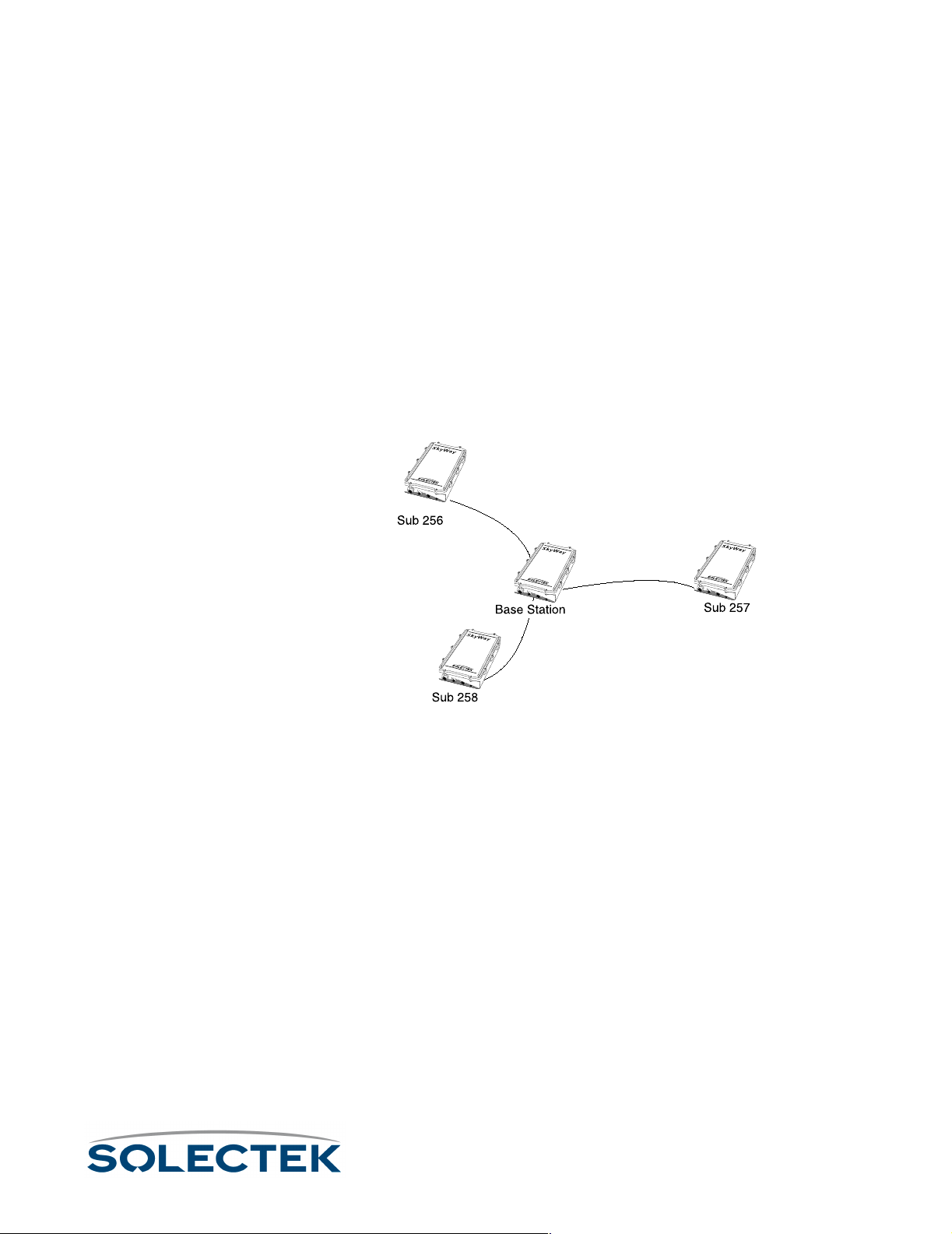
Understanding RF-DLC
Understanding RF-DLC
The following is a discussion of the RF-DLC protocol, which provides you with background information before you begin configuration.
The RF-DLC Protocol
RF-DLC is a proprietary protocol based on the HDLC protocol. It is a polling protocol
for star-based networks with a base station and one or more substations, and participates in transmitting frames from one station to another. The base station controls
communications with each sub station and maintains the RF link. The base station communicates with one sub station at a time. The sub stations communicate only with the
base station and not with each other.
In the following diagram showing a point-to-multipoint configuration, the base station
communicates with the sub stations in a star topology.
In a point-to-point configuration, there is one base station and one sub station.
Automatic Discovery Protocol
When a sub station begins operation, it can receive packets but may not be able to fully
communicate with the base station until the base station is configured to recognize it.
RF-DLC uses another protocol called Automatic Discovery Protocol (ADP) to learn
about a sub station and begin communicating with it. Once the base station assigns a
sub-station number to the sub station, the base station then uses the RF-DLC protocol
to continue communications.
Enabling ADP
The base station is enabled for ADP on the RF-DLC base port by default. With ADP
enabled, the base station can use ADP to identify and set up an unassigned sub station.
The discovery process is outlined below.
With ADP enabled, you must choose the ADP mode, which specifies how the sub station handles broadcasts: either Auto Acceptance or Manual Acceptance.
65
Page 92

•Using Auto Acceptance, the base station automatically accepts the sub station.
•Using Manual Acceptance, you must manually accept each sub station by
enabling the Accept Status field (in “1.2.3.1.4 ADP Substation Configuration” on
page 81) for that Sub Station Number.
Disabling ADP
When configuring the base station, you may choose to disable ADP, which can result in
reduced overhead. If you disable ADP, you must manually assign the base sub ports for
the sub stations by using 1.2.3.1.3 RF Base Sub Port Configuration, described in detail on
page 80. to enter the Sub-Station Number and IP address information. On the sub station,
you must also manually set up the RF sub ports, entering in the same Sub-Station Number
in “1.2.3.1.2 RF Sub Port Configuration” on page 78.
If ADP is disabled, the ADP polling operation does not apply (see “ADP Discovery Process” on this page).
ADP Discovery Process
The discovery process is as follows when ADP is enabled:
• The base station is not yet aware of the sub station, and the sub station is waiting
for an ADP request from the base. The base station sends out a broadcast
request at the broadcast address of 255.
• The sub station replies to the broadcast with its IP address.
• The base station sends another broadcast to assign the station address (Sub-sta-
tion Number). The base station assigns the next available address to the sub station. This is the base sub port address for the sub station in the range of 256 to
512.
• The base station can now communicate with the sub station using RF-DLC
frames:
66
Page 93

Understanding RF-DLC
RF-DLC Frame Types
RF-DLC frames contain an address field which defines the sub station address, broadcast address, or group address. RF-DLC frames also contain a control field containing
commands, responses, and counts used to maintain the link. The control field formats
are:
• Unnumbered - used to initialize the sub station and send information using an
unreliable mechanism.
• Supervisory - used to acknowledge the receipt of information frames, convey
ready or busy conditions, and report frame numbering errors.
• Information Transfer - used to transfer data using a reliable mechanism. Information frames are numbered, meaning the control field contains Ns counts,
which ensure frames are received in their proper order, and Nr counts, which
confirm that information frames were received and accepted.
The RF-DLC frame also contains a CRC bit for error checking.
RF-DLC Commands and Responses
The base station sends a command to the sub station, which sends back a response.
Commands and Responses are of Unnumbered, Supervisory, or Information format.
Note The 2.5.1 Base Port Status screen provides the status of frame activity. For descriptions
of RF-DLC commands and responses, see 2.5.1 RF-DLC Base Port Status, described
in detail on page 140, and 2.5.2 RF-DLC Sub Port Status, described in detail on
page 143.
Polling
The base station polls the substations one at a time to see if they have packets to send
to the base station.The base station manages three poll lists to which it assigns devices,
based on their activity:
•Substations on the Fast Poll
order by the base. The polling frequency is contingent upon the number of
substations.
• A substation drops to Slow Poll
times with no response. A sub can also drop to Slow Poll if it responds with “n”
RRs and there is no data in either direction.
• A substation drops to Inactive Poll
•While being on Slow Poll, the sub does not respond to the base in 8 tries.
•It is the only sub station to respond to the base with RR responses and no
data in either direction.
Fast Poll list are constantly being polled one at a time in
Fast PollFast Poll
Slow Poll if it does not respond to the base station in 4
Slow PollSlow Poll
Inactive Poll if either of the following events occurs:
Inactive PollInactive Poll
Consider a base station with three sub stations on the fast poll list, two substations on
the slow poll list, and one on the inactive poll list. The slow poll timer is set to one
67
Page 94

minute and the inactive timer is set to five minutes. The slow poll timer’s value is
always less then that of the inactive timer.
The base station polls the fast poll sub stations until one minute has passed. Then it
polls the sub stations on the slow poll list, then moves back to poll the fast poll sub stations, and continues in this fashion until five minutes has passed. The base station then
polls the inactive sub station and always broadcasts an ADP packet, if ADP is enabled.
Error Detection and Recovery
I-frames (data frames) can contain several Bridged-Ethernet frames or routed IP datagrams. They are sequence numbered: Ns is the frame number, Nr is an ACK, meaning
all frames 'r' were received.
If the base station gets an I-frame out of sequence, it assumes one was missed and
sends out a reject packet. Errors are handled as follows:
• If Ns gets ahead by one, the packet is rejected. The other side retransmits.
• If Nr changes and a frame is acknowledged but was not sent out, the base
sends back a disconnect to the sub station, or the sub station sends a FRMR
(Frame reject response) to the base station. This is a logical disconnect, the RF
physical link is maintained.
• The sub station resets and the base makes an attempt to re-establishes the RFDLC session on the next polling cycle.
68
Page 95

Configuring the Ports
Configuring the Ports
How you configure the SkyWay Bridge/Router depends on your network topology.
Configure each unit separately depending on its role as a base station or sub station,
and its function as a bridge, router, or both bridge and router.
Note Serial Port configuration is discussed in Chapter 2 (see “1.2.1.1 Serial Port Configura-
tion” on page 24).
Before you Begin
The following helps you determine how to configure the unit:
1. Decide if the unit will be a base station or a sub station.
2. Decide if the unit will perform bridging, routing, or both bridging and routing. The
default configuration is bridging enabled, routing disabled.
3. If you are configuring the unit for routing, have the IP configuration data ready (IP
address, IP Mask, etc.).
When you make changes to the screens and type .W, you update the configuration
database. However, for some changes, such as configuring the RF ports, you must
cycle the port to start the new configuration. This is described in “Configuring the SkyWay as a Base Station” on page 69.
Obtaining IP Addresses
IP network addresses are unique numbers assigned by the Internet Assigned Numbers
Authority (IANA) (see RFC 2050). See your system manager to obtain IP addresses. If
your network is not connected to the Internet directly or indirectly, see RFC 1918,
which defines class C addresses in the range of 192.168.0.0 - 192.168.255.0 that you
may use.
Setting up IP Addresses
Each unit, whether a base station or a sub station, must have a unique IP address for
the RF port, even if you are enabling bridging only. The system derives the RF MAC
address from the RF IP address. If you are enabling routing, you also need to set up the
IP address for the Ethernet port (for more information, see “1.4.2 IP Port Configuration” on page 95).
Configuring the SkyWay as a Base Station
1. Set up a unique IP address for the RF Port.
a. Go to screen 1.4.2 IP Port Configuration, described in detail on page 95.
b. For Port # 3 (the RF port), enter the IP Address and the IP Mask.
c. Press .W to update the database.
69
Page 96

2. Configure the RF Transceiver settings: RF Frequency, RF Data Rate, and Scrambler
Ta p V al ue s.
a. Go to screen 1.2.3.3 RF Transceiver Configuration, described in detail on
page 72.
b. Set the RF Frequency, RF Data Rate, and Scrambler Tap values.
c. Press .W to update the database.
3. Invalidate the RF Diagnostics Port configuration. As shipped, the default RF port is
the RF-DLC Sub Diagnostics Port. You must invalidate it before setting the RF port
up as a base port.
a. Go to 1.2.3.2 RF Diagnostic Port Configuration, described in detail on
page 73. The port number is 3, and the port type is Sub Diag, which is the
default.
b. Set the Record Type field to Invalid.
c. Press .W to remove this configuration record from the database.
4. Configure the RF port as a base port.
a. Go to 1.2.3.1.1 RF Base Port Configuration, described in detail on
page 74.
b. Press .A. This automatically adds port 3 as a base port. The fields now
contain the default settings.
5. Accept the defaults or change the base port configuration settings:
• Configuration Status - You might want to set this Off-line to complete configuring all your units, then change the configuration status of all units to On-line
before rebooting (see step 5).
• Max Buffers - these are the message buffers for the system.
• Transmit and Receive Buffers - these are shared between the serial and RF
ports. There are 512 total.
• Maximum Frame Size - The physical MTU (not configurable).
• Slow Polling Timeout - number of seconds that elapse before the base station
checks the sub stations on the slow poll list.
• First Sub Station Number - logical address of the first sub station (default is
256).
• Last Sub Station Number - logical address of the last sub station in the topology.
• Automatic Discovery Protocol - if enabled, the base station uses ADP to send
broadcasts to the sub stations. You must also configure the ADP mode. If disabled, ADP mode does not apply, there fore you must manually configure the
base station for the base sub ports (see “Configuring the Base Sub Ports” on
page 80).
70
Page 97

Configuring the Ports
• ADP mode - applies only if Automatic Discovery Protocol is enabled. Auto
Acceptance is the default. If you set ADP mode to Manual Acceptance, you
must configure the base station to manually accept the sub stations.
• ADP Timeout Interval - applies only if Automatic Discovery Protocol is
enabled.
When finished setting the base port configuration, type .W to update the database.
6. Initialize the RF port. At this point, you have made the changes to the database, but
before the changes take affect, you must initialize the port. There are two ways to
do this:
• Cycle the port:
a. Go to 2.2.1 Generic Port Status and Control.
b. Type 3 (or
c. Set the Administrative Status field to Cycle.
d. Type .W
Cycle evacuates the port, eliminates the driver, reads the database, reinstalls the driver,
and brings up the port.
• Reset the unit:
a. Go to the Main Menu
b. Type 5 (Start Application).
c. Choose Run Time as the Application to Start.
This reloads the updated database containing the new configuration parame-
ters.
You can configure only one base station, but you can configure as many as 64 sub
stations.
.N until the port number is 3).
71
Page 98

1.2.3.3 RF Transceiver Configuration
Use this screen to set RF Frequency, RF Data Rate, and Scrambler Tap values.
1.2.3.3. RF Transceiver Configuration Record 1 of 1
RF Port RF Frequency RF Data Rate Scrambler Tap
------- ------------ ----------- ----------- 3 2468 Mhz 2 Mbps 72
\ - return to menu . - commands TAB - next available field ENTER - edit
Field Name MIB
Settings (default in
bold)
RF Port [swRFTransCfgIndex] 3
The RF port number is 3.
RF Frequency [swRFTransCfgFrequency] 2468 Mhz
The transmitted and received frequency for this SkyWay. This setting must match all
other stations communicating with this SkyWay.
RF Data Rate [swRFTransCfgDataRate] • 2 Mbps
• 5.5 Mbps
• 11 Mbps
This setting must match all other stations communicating with this SkyWay.
Scrambler Tap [swRFTransCfgScrambler-
72
Ta p ]
Determines how the SkyWay scrambles data between two units. This setting must
match all other stations communicating with this SkyWay.
72
Page 99

Configuring the Ports
RF Diagnostics Port
There are two diagnostic ports, the RF-DLC Base Diagnostic port and the RF-DLC
Sub Diagnostic port. Both of these use the control interface of the RF driver to perform
RF diagnostics.
1.2.3.2 RF Diagnostic Port Configuration
1.2.3.2 RF Diagnostic Port Configuration Record 1 of 3
Port Number :3
Configuration Status :On-line
Port Type :RF-DLC SUB Diagnostic Port
Max Buffers :800
Transmit Buffers :240
Receive Buffers :180
Maximum Frame Size :1549
Record Type :Valid
\ - return to menu . - commands TAB - next available field ENTER - edit
The following table lists the field name, the MIB name, and field options with the
default setting in bold:
Field Name MIB
Settings (default in
bold)
Port Number [swRFDiagPortIndex] 3
The RF port number.
Configuration Status [swRFDiagPortConfigSta-
tus]
• On-line
• Off-line
Determines if this port is initialized upon reset. Off-line prevents the port from being
initialized upon reset.
Port Type [swRFDiagPortPorttype] RF Sub Diagnostics Port
RF Sub Diagnostic port.
Max Buffers [swRFDiagPortMax-
800
Buffers]
The number of message buffers.
Transmit Buffers [swRFDiagPortTransDesc] 240
The number of transmit buffers.
73
Page 100

Field Name MIB
Settings (default in
Receive Buffers [swRFDiagPortRecvDesc] 180
The number of receive buffers.
bold)
Maximum Frame Size [swRFDiagPortmax-
3200
FrameSize]
The physical MTU, or largest frame that can be transmitted. This field is not configurable.
Record Type [swRFDiagPort] • Valid
• Invalid
The status of this configuration.
1.2.3.1.1 RF Base Port Configuration
1.2.3.1.1 RF Base Port Configuration Record 1 of 1
Port Number : 3
Configuration Status : Off-line
Port Type : RF-DLC Base Port
Max Buffers : 800
Transmit Buffers : 240
Receive Buffers : 180
Maximum Frame Size : 3200
Slow Polling Timeout-seconds : 15
First Sub Station Number : 256
Last Sub Station Number : 287
Automatic Discovery Protocol : Enabled
ADP Mode : Auto Acceptance
ADP Timeout Interval-seconds : 60
74
Record Type : Valid
\ - return to menu . - commands TAB - next available field ENTER - edit
The following table lists the field name, MIB, and settings with the default setting in
bold. If only one setting is shown, it is the default:
Field Name MIB
Settings (default in
bold)
Port Number [swRFBasePortIndex] 3
The RF port number.
 Loading...