

SOLE ST100-YT33 Service Manual
SSTT110000--YYTT3333 TTrreeaaddmmiillll
SSeerrvviiccee MMaannuuaall

WARNING:
ALWAYS UNPLUG THE TREADMILL FROM THE ELECTRICAL
OUTLET BEFORE SERVICING THE UNIT.

SSeerrvviiccee MMaannuuaall
TTaabbllee ooff CCoonntteenntts
s
TTaabbllee ooff CCoonntteennttss 11
TABLE OF CONTENTS
Table of Contents...................................................................... 1
Table of Figures ........................................................................ 3
Description................................................................................ 4
A E
LECTRICAL CONFIGURATION
....................................... 4
1. ST100-YT33 Treadmill components ........................ 4
1. Console ...................................................................... 5
2. Main controller.......................................................... 5
3. Treadmill motor ........................................................ 5
4. Incline motor............................................................. 5
Operation................................................................................... 7
A W
INDOW DISPLAY MODE
............................................... 7
1. OFF Mode................................................................. 7
2. READY Mode .......................................................... 7
3. RUN Mode................................................................ 7
4. SLEEP MODE .......................................................... 7
B F
UNCTION
........................................................................ 8
1. SPEED ...................................................................... 8
2. Incline ....................................................................... 8
3. TIME......................................................................... 8
4. DISTANCE............................................................... 8
5. CALORIES ............................................................... 9
6. PULSE ...................................................................... 9
7. LAPS......................................................................... 9
C F
UNCTION BUTTON IN MAIN MODE
............................... 9
1. READY MODE ...................................................... 10
2. RUN MODE ........................................................... 10
D CALIBRATION P
ROCEDURE ................................. 11
1. Calibration............................................................... 11
Troubleshooting ...................................................................... 13
1. General.................................................................... 13
2. Troubleshooting Matrix .......................................... 14

SSeerrvviiccee MMaannuuaall
TTaabbllee ooff CCoonntteenntts
s
TTaabbllee ooff CCoonntteennttss 22
3. controller debugging form ...................................... 21
Diagrams and Schematics ....................................................... 22
APPENDIX A......................................................................... 25
1. TREADBELT ADJUSTMENT .............................. 25
APPENDIX B ......................................................................... 27
1. TREADMILL LUBRICATION ............................. 27
APPENDIX C ......................................................................... 28
1. RESET SWITCH RESETTING ............................. 28
APPENDIX D......................................................................... 29
APPENDIX E ......................................................................... 30
1. SPEED SENSOR ADJUSTMENT......................... 30
2. SERVICE QUESTIONS......................................... 30

SSeerrvviiccee MMaannuuaall
TTaabbllee ooff FFiigguurrees
s
TTaabbllee ooff FFiigguurreess 33
TABLE OF FIGURES
Figure 1 Operational Flowchart ............................................... 6
Figure 2 Console Layout........................................................ 22
Figure 3 Mechanical Layout .................................................. 22
Figure 4 Main Controller information & voltages ................. 23
Figure 5 Function JK1 connector on Main Controller........... 23
Figure 6 Wiring Diagram........................................................ 24
Figure 8 If Treadbelt slips...................................................... 25
Figure 9 If tread belt shifts too far to the Right ..................... 25
Figure 10 If tread belt shifts too far to the Left...................... 26
Figure 11 Resetting Reset switch........................................... 28

SSeerrvviiccee MMaannuuaall
DDeessccrriippttiioonn
DDeessccrriippttiioonn 44
DESCRIPTION
A E
LECTRICAL CONFIGURATION
Note: Electrical servicing of this treadmill is limited to board
level replacement.
1. ST100-YT33 TREADMILL COMPONENTS
a) Safety key:
To fits on the Console that activate all functions. If no safety
key, console can not be controlled.
b) Console:
Interface that controls all functions of the treadmill.
c) Main controller:
The circuit board consist of the DC power supply for
console、incline driver and DC motor driver, link the
console to output appropriate voltages for motor that
control the treadmill functions.
d) Treadmill motor:
This is a variable speed for DC motor. To control the 0 –90
voltages on the main controller, it can to increase or
decrease speed of running belt.
e) Incline motor:
This is an ac motor. User can to control variable
elevation by console within main controller.

SSeerrvviiccee MMaannuuaall
DDeessccrriippttiioonn
DDeessccrriippttiioonn 55
B.
GENERAL INFORMATION
1. CONSOLE
a) Contains LCD windows which are twenty rows of "dots"
(8high) indicate each segment of a workout. DISTANCRE
,
CALORIES,PULSE,TIME,SPEED,INCLINE.
2. MAIN CONTROLLER
a) Include power supply 、 motor driver control circuit and incline control
circuit.
3. TREADMILL MOTOR
a) It’s a variable speed on 0-90 volt DC motor.
b) Have three wires red, black and green.
c) If there is DC voltage on the Red wire (M+) the treadmill motor will turn
clockwise.
d) If there is DC voltage on the Black wire (M-) the treadmill motor will turn
counter-clockwise.
e) The higher the voltage the faster the motor turns.
f) The green wire is ground.
4. INCLINE MOTOR
a) This is a 110 volt AC motor.
b) Have four wires, red, black, white and green.
c) Has one 3 pins cable of position sensor.
d) If there is AC voltage on the Red wire (UP) the incline motor will increase the
incline.
e) If there is AC voltage on the Black wire (DOWN) the incline motor will
decrease the incline.
f) The White wire (COM) is neutral.
SSeerrvviiccee MMaannuuaall
DDeessccrriippttiioonn
DDeessccrriippttiioonn 66
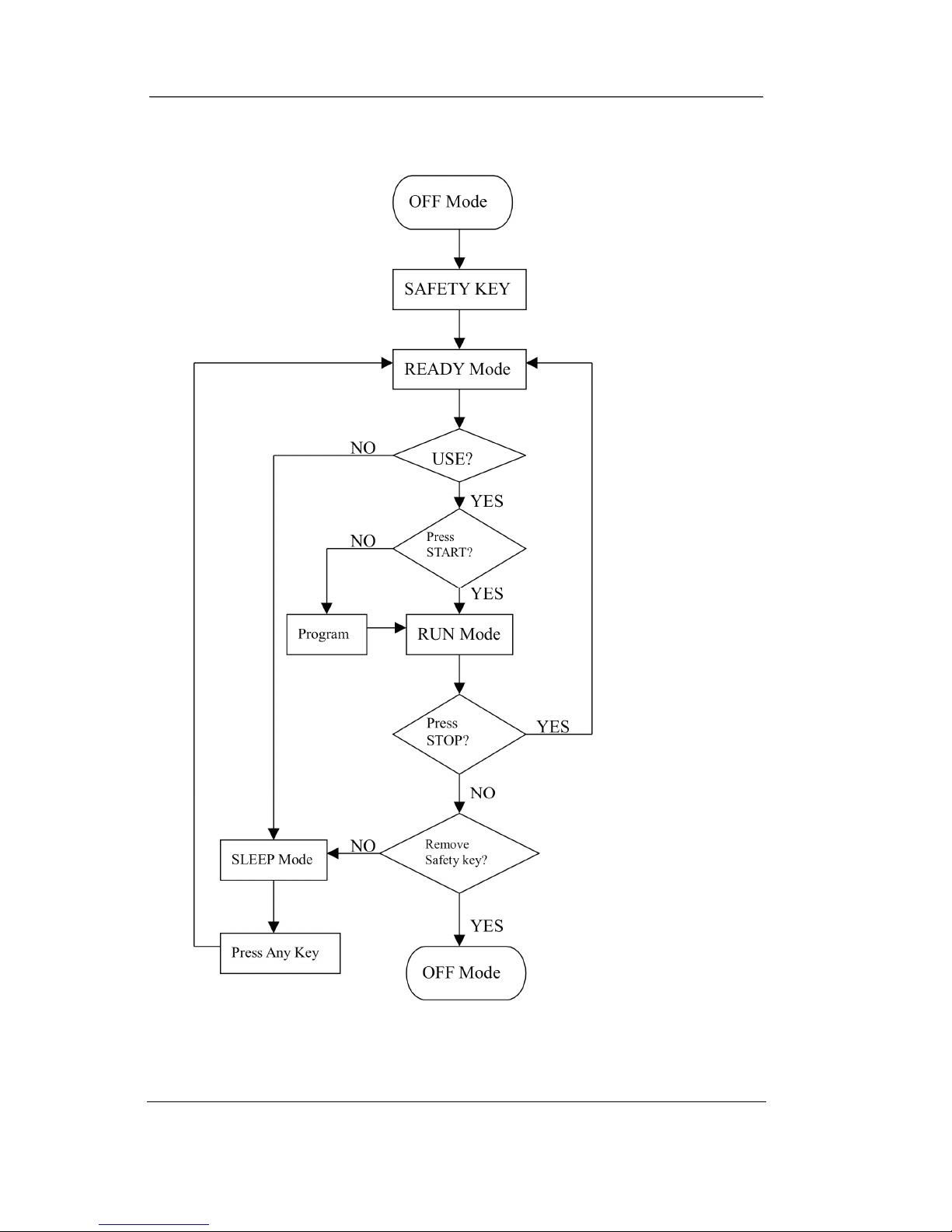
Figure 1 Operational Flowchart

SSeerrvviiccee MMaannuuaall
OOppeerraattiioonn
OOppeerraattiioonn 77
OPERATION
A W
INDOW DISPLAY MODE
1. OFF MODE
a) When user doesn’t insert the SAFETY KEY on the console, the treadmill
enters the OFF Mode and all windows will appear blank.
2. READY MODE
a) When the treadmill is ON and the sfasekey is in released status in console,
( LCD windows and twenty rows "dots" (8high)) 7 SEGMENT LED display
"0:00", MANUAL LED will be bright, the LAP light s run a circle each
second.
b) TIME, DISTANCE and CALORIES Values will all be saved when RUN
Mode enters READY Mode.
c) In READY Mode, if user doesn't press any button for 30 minutes it will
automatically turn off (blank out).
d) Console will display current software version in MESSAGE window;
DISTANCE window displays total accumulated working distance; TIME
window displays total accumulated working time.
e) Incline will be calibrated to zero automatically. If incline is faulty, INCLINE
window will display ERR (At this time, incline is non-function but other
functions are normal.
3. RUN MODE
a) In RUN Mode, pressing the “STOP” button and removing the SAFETY
KEY will cause the treadmill stop instantly and enter OFF Mode.
b) Display will automatically shift every 5 seconds.
c) Press "Display" button to exchange the displaying of LED which includes
laps of Track, Incline profile and Speed profile.
4. SLEEP MODE
a) In SLEEP Mode, if any buttons are pressed then the treadmill
enters READY Mode.

SSeerrvviiccee MMaannuuaall
OOppeerraattiioonn
OOppeerraattiioonn 88
B F
UNCTION
1. SPEED
a) Display the current speed in Kilometer per hour.
b) DISPLAY range is 0.0 to 99.9 mph.
c) WORK range is 1 to 18 km(0.5/12MPH).
d) Press Speed↑“FAST” or Speed↓”SLOW” to adjust speed, each increment
and decrement is 0.1 mph.
2. INCLINE
a) Display the incline position from 0 to 15.
b) DISPLAY range is 0 to 999.
c) WORK range is 0 to 15.
d) INCLINE preset value is 0 to 15.
e) Press “UP” or ”DOWN” to adjust incline, each increment and decrement is 1.
3. TIME
a) TIME is either COUNT UP or COUNT DOWN. System preset is COUNT
UP; if user sets the time then timer is COUNT DOWN.
b) DISPLAY range is 0:00 to 99:59.
c) WORK range is 0:00 to 99:59.
d) COUNT DOWN setup range is 10:00 to 99:00.
e) When TIME is set, the count will go to zero.
f) In RUN Mode, press “START” button to save value of time and enter “RUN
Mode” again that value will continue count up time.
4. DISTANCE
 Loading...