

SOLE SE578SA Service Manual
SE578SA Elliptical Service Manual
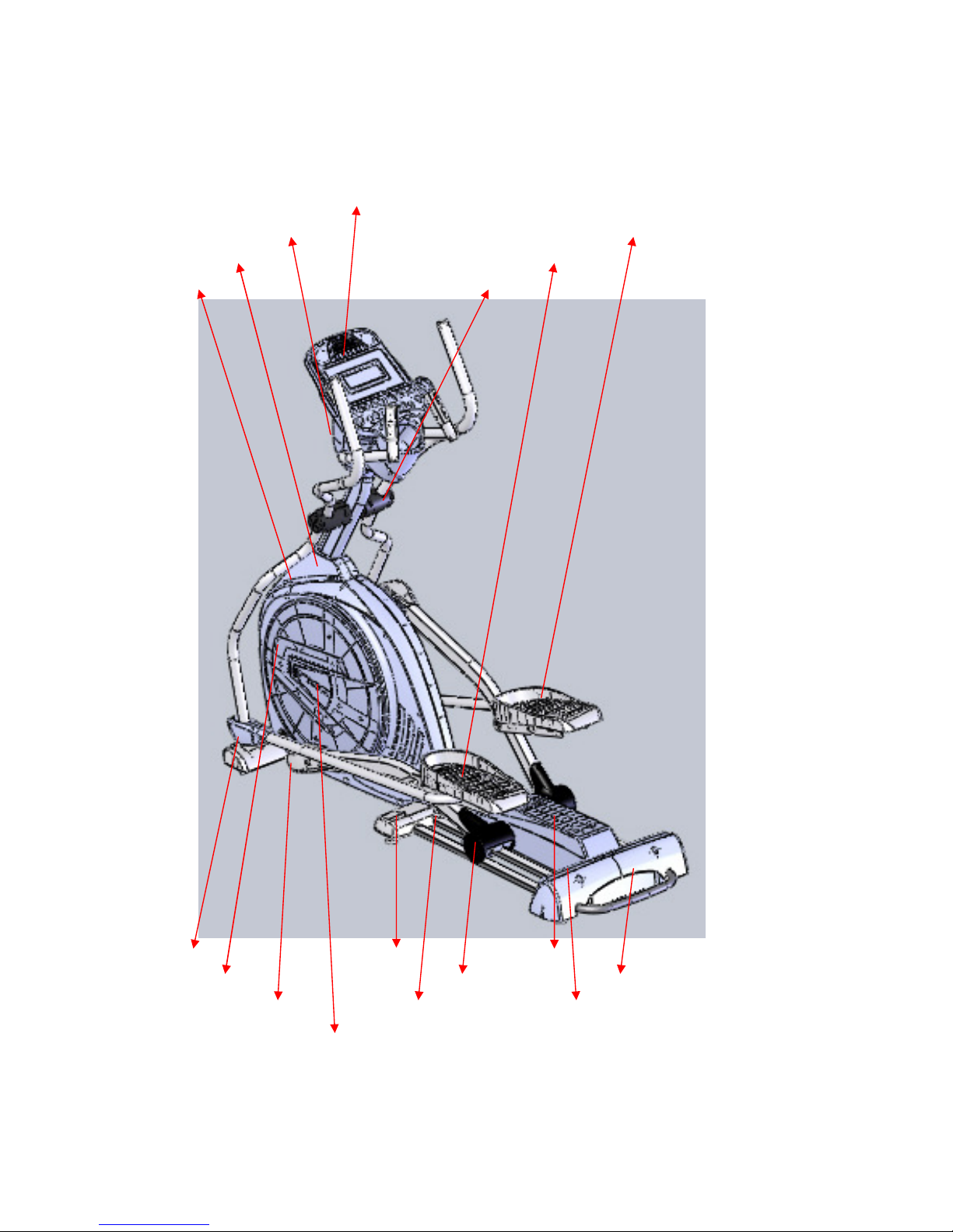
I. Plastic Parts
Console
Rear Console Cover R Pedal
Console Mast Cover L Pedal
Side Case R Handle Bar Cover (F/R)
Connecting Arm Cover (L/R) M Stabilizer Cover Incline Cover
Round Disk Slide Wheel Cover Rear Bar Cove
Pedal Arm Cover Incline Bottom Cover Inclinable Rail Cover
Round Disk Cover
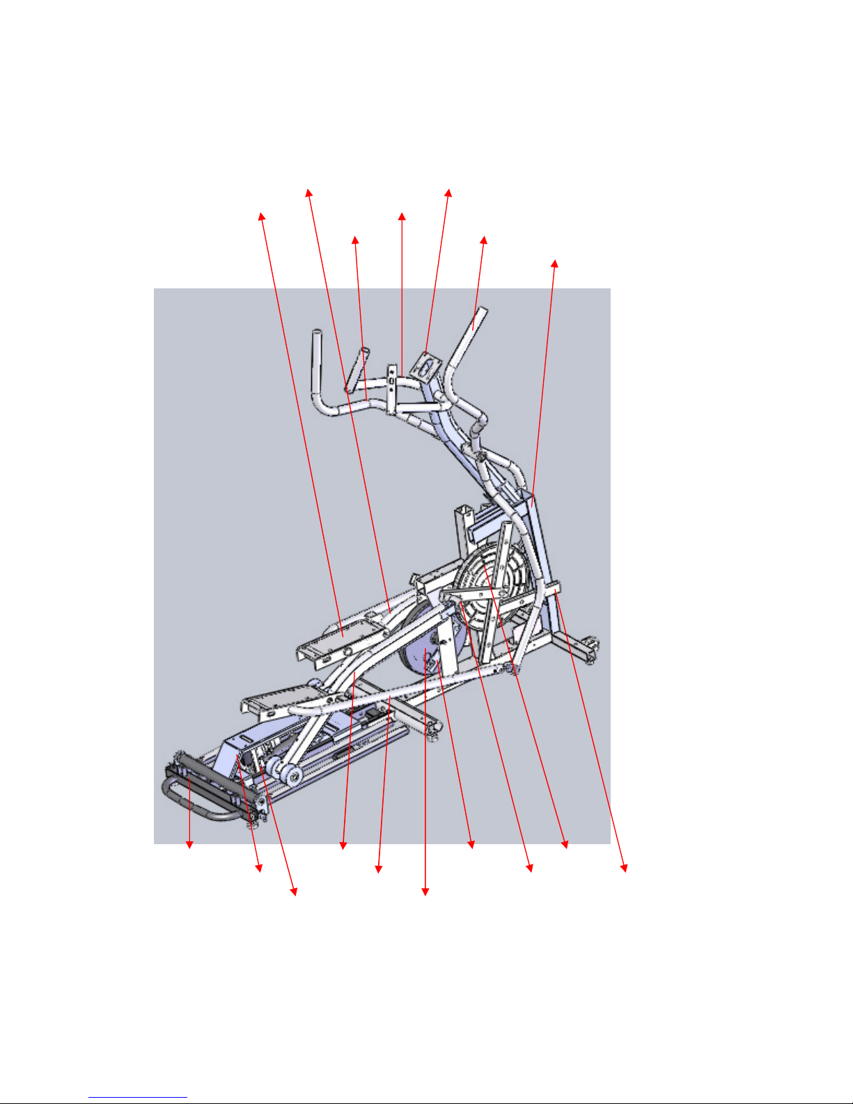
II. Skeleton
L Pedal Arm Console Holder Assembly
L Connecting Arm Console Mast
L Swing Arm R Swing Arm
Main Frame
Rail Base Assembly R Pedal Arm Idler Wheel Assembly Drive Pulley
Rear Rail Assembly R Connecting Arm Bushing Housing Cross Bar
Incline Motor Flywheel

Contents:
I. Replacing Parts
1. Console Assembly
2. Connecting Arm Assembly
3. Pedal Arm Assembly
4. Side Cases
5. Cross Bar Assembly
6. Drive Belt
7. Idler Wheel Assembly
8. Flywheel
9. Bushing Housing
10. Slide Wheels
11. Incline Motor
II. Troubleshooting
1. Console Assembly
2. Side Cases and Round Disk
3. Flywheel
4. Drive Belt
5. Swing Arms
6. Bushing Housing
7. Pedal Arm, Connecting Arm and Slide Wheels
8. Incline Motor and Incline Controller
III.
Q&A
1. Noises
2. Slippage
3. Play
4. Smoothness
5. Other Issues
Model SE578SA Service Replacing Parts
Parts 1 Console Assembly Rev.
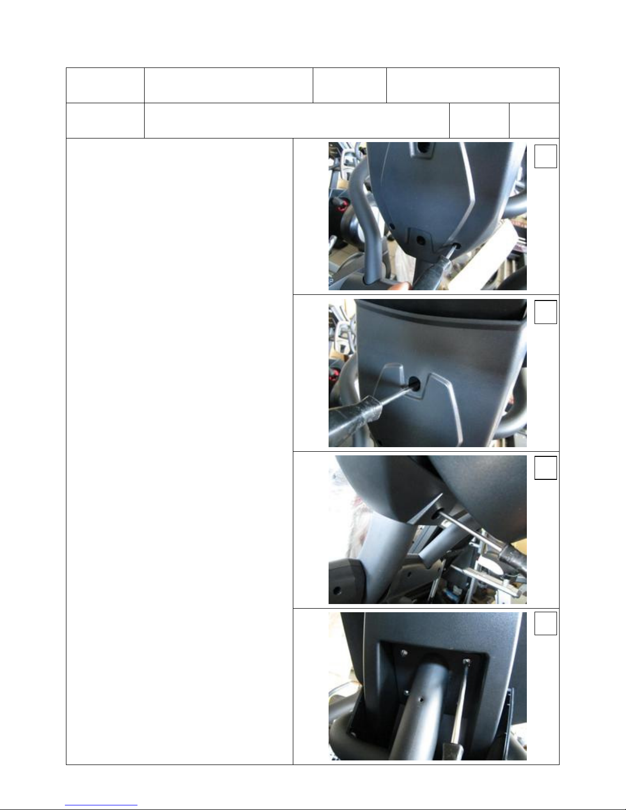
Procedures:
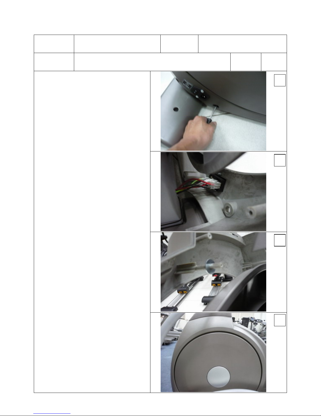
1. Use Phillips head screw driver to
release three M5x15mm Phillips head
screws and two 3.5x12 m/m Sheet
Metal Screws to take apart front and
rear Mast Covers, as shown in figures
1, 2 and 3.
2. Use Phillips head screw driver to
release four M5x10mm Phillips head
screws and disconnect Computer cable,
Handle Resistance Wire, Handle
Incline wire and Handpulse Cable to
take Console apart, as shown in figure
4.
3. Reverse above steps to resume
console. (Be sure not to pinch wires)
4. Release 3.5x12 Sheet Metal Screws if
opening top and bottom console
covers is necessary. (To be opened by
professionals only)
1
2
3
4
Model SE578SA Service Replacing Parts
Parts 2. Connecting Arm Assembly Rev.
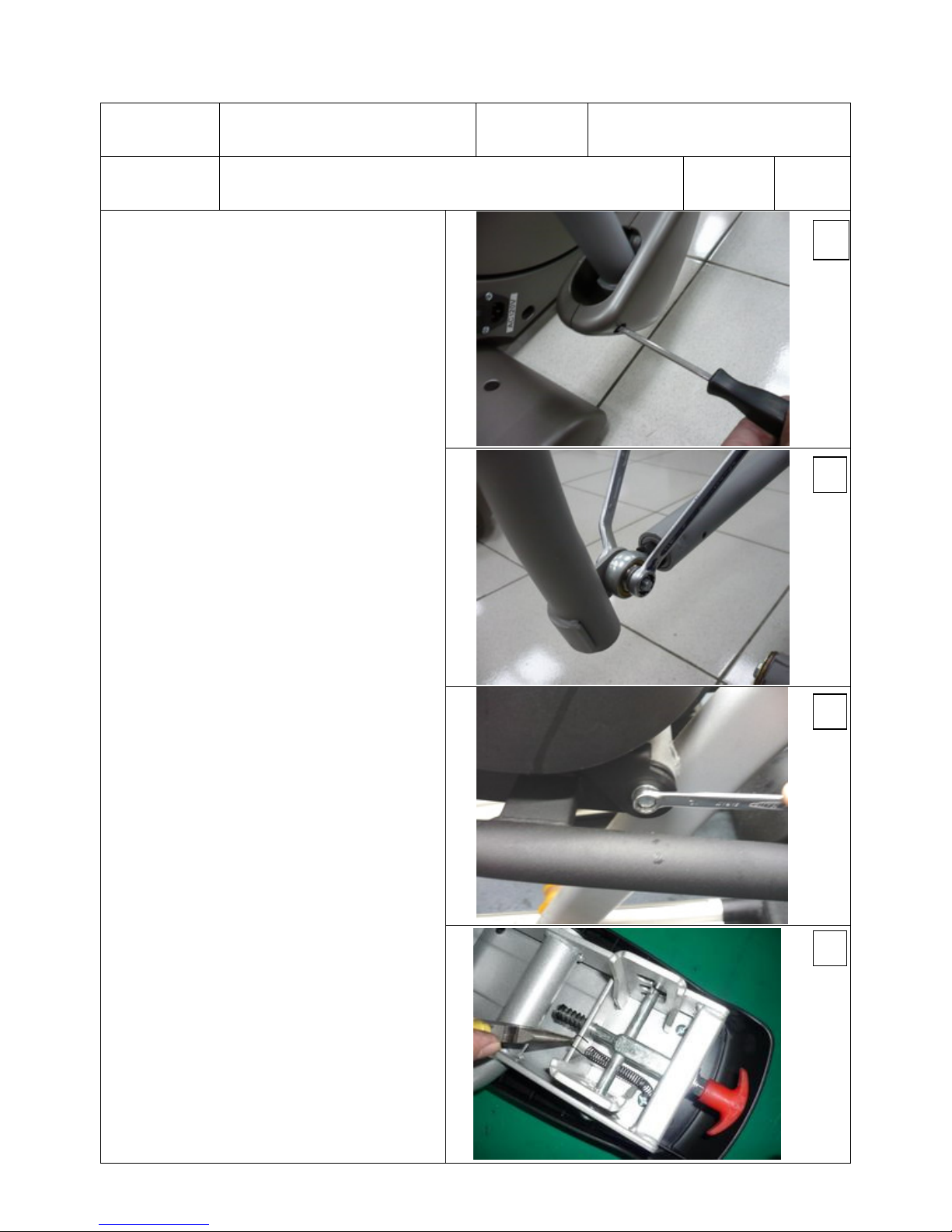
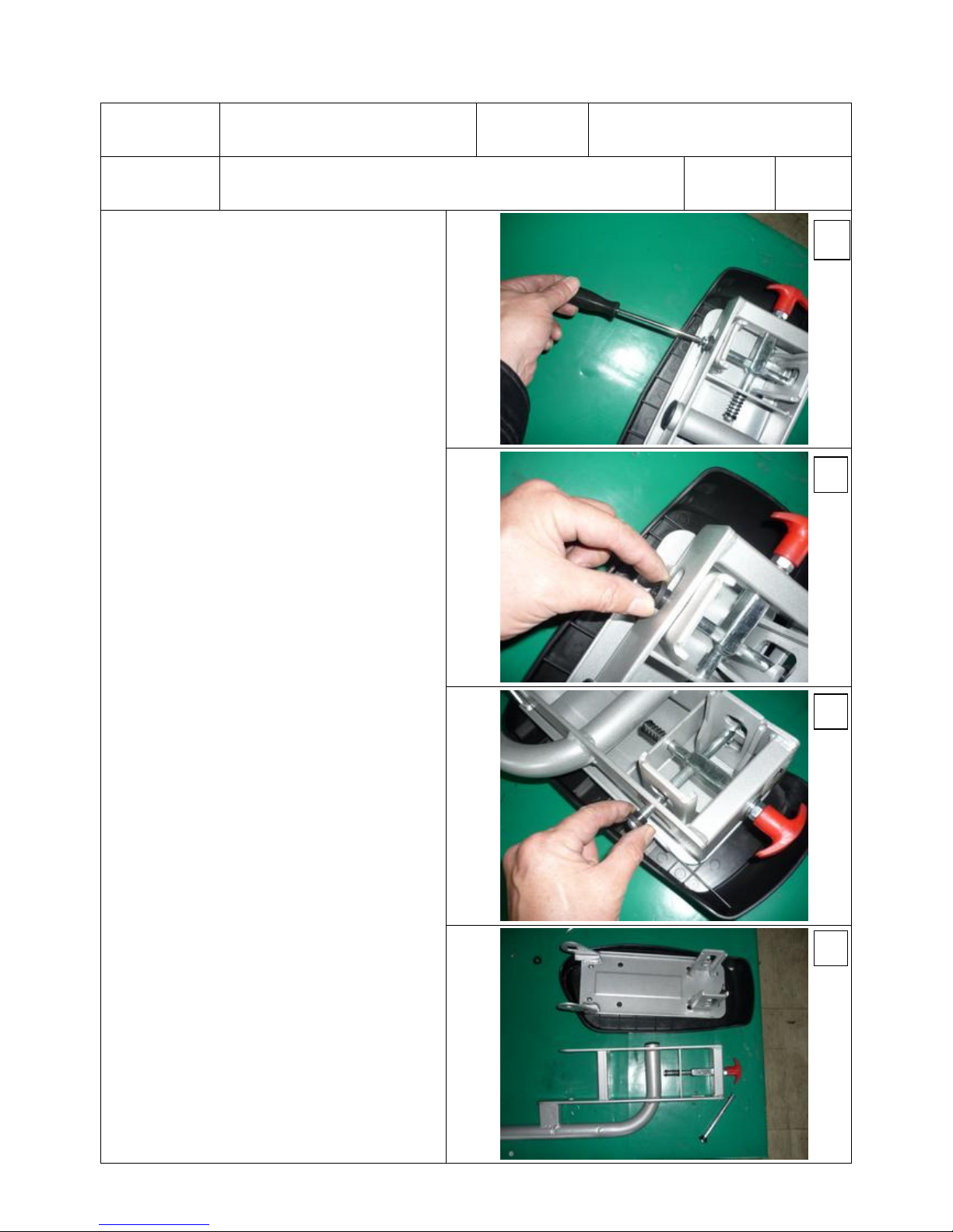
Procedures:
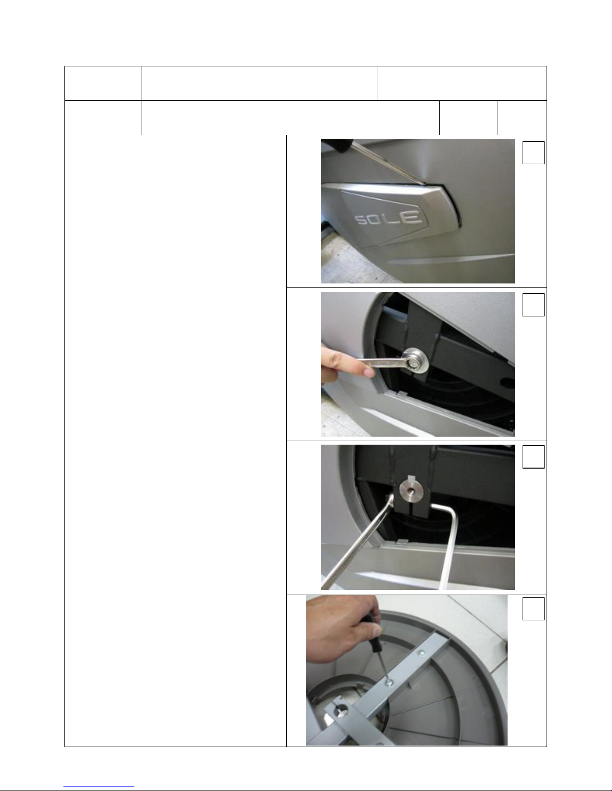
1. Use Phillips head screwdriver to
release Connecting Arm Covers, as
shown in figure 1.
2.
Use 12 and 13 mm wrenches to release
5/16" x1-1/4" hex head bolt, 5/16" x
20 x 1.5T flat washer and 5/16" x 7T
nut which secure the Fish-
Eye bearing,
as shown in figure 2.
3.
Use 12 mm wrench to release 5/16" x
15m/m hex head bolt and 5/16" x 20
x1.5T flat washer and Pedal Carriage
Bolt to take apart the Connecting Arm
Assembly, as shown in figure 3.
4.
To take apart the Pedal Assembly, first
release the tension spring, as shown in
figure 4.
1
2
3
4
Model SE578SA Service Replacing Parts
Parts 2. Connecting Arm Assembly Rev.
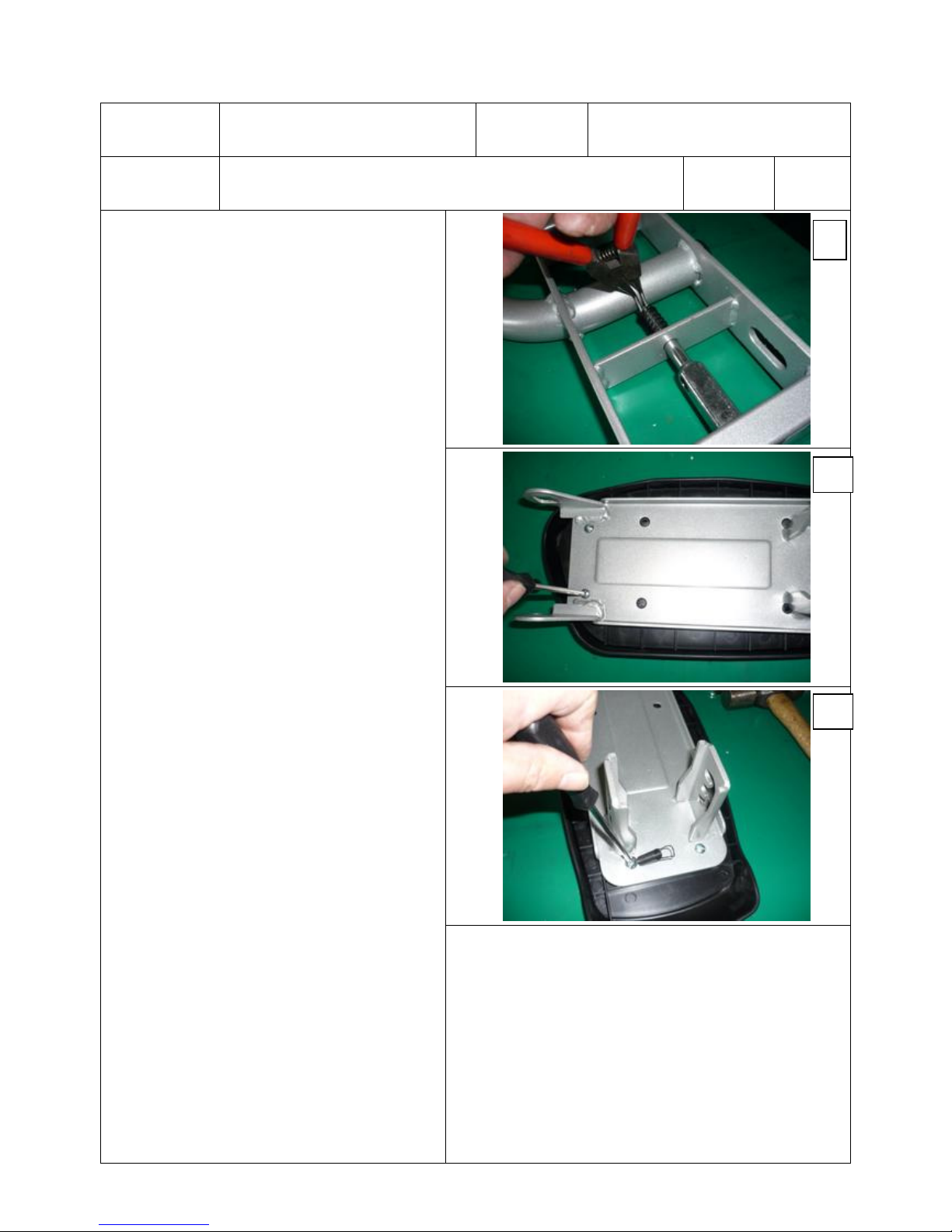
Procedures:
5. Next use Phillips head screwdriver to
release 4pcs of M5x10mm Phullips
head screws, as shown in figure 5.
6. Then take apart the plastic bushing ψ
14xψ10 and pull out the shaft (Use
plastic hammer if necessary) and
separate Adjustable Pedal from the
Connecting Arm Assembly, as shown
in figures 6, 7 and 8).
5
6
7
8
Model SE578SA Service Replacing Parts
Parts 2. Connecting Arm Assembly Rev.
Procedures:
7. Use C-ring pliers to release C-ring ψ
10 and take apart the Locking Pin
Assembly, as shown in figure 9.
8. Release 4 M5x10mm Phillips head
screws to take the pedal apart, as
shown in figures 10 and 11)
9. Reverse above steps to resume all
parts. Remember to return the latch
spring and resume adjustable pedal,
Connecting Arm Assembly back on the
Pedal Arm assembly and lock with
Carriage Bolt. Finally, tighten with
5/16" x 15m/m hex head bolt together
with 5/16" x 23 x 1.5T flat washer.
9
1
11
10
Model SE578SA Service Replacing Parts
Parts 3 Pedal Arm Assembly Rev.
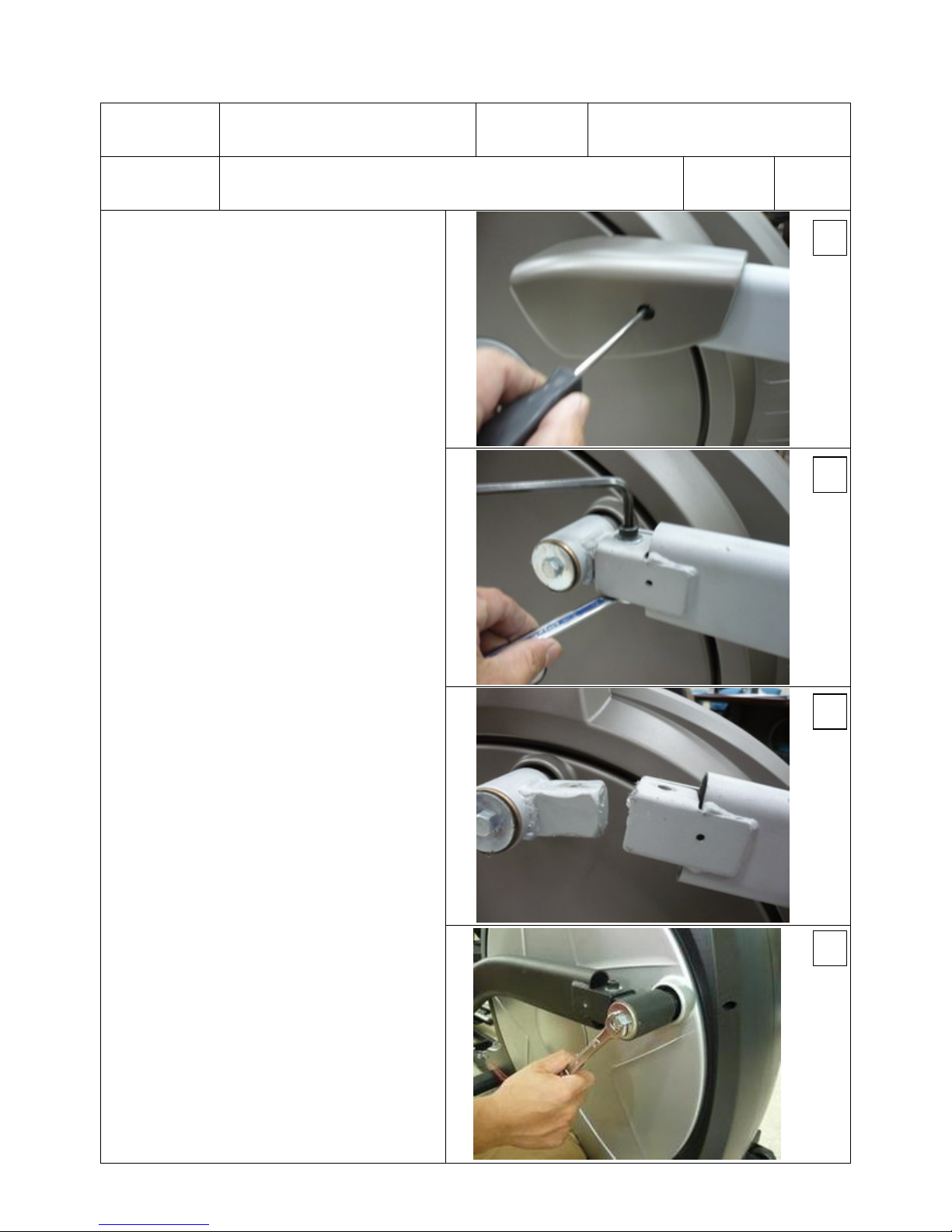
Procedures:
1. Follow the procedure 2 to take apart
the Connecting Arm Assembly.
2. Use Phillips head screwdriver to
unscrew Pedal Arm Cover, as shown
in figure 1.
3.
Use M8 and 14mm wrenches to release
3/8”x 2-1/4”socket head cap screw,
2pcs of 3/8"×19×1.5T flat washers
and 3/8”x 11T Nylon nut and take
apart Pedal Arm Assembly, as shown
in figures 2 and 3.
4. To take the Bushing Housing apart,
use 12mm wrench to release 5/16" x
15m/m hex head bolt and 5/16" x 35
x1.5T flat washer, as shown in figure
4.
5. Reverse above steps to resume all
parts.
1
2
3
4
Model SE578SA Service Replacing Parts
Parts 4 Left and right Side Cases Rev.
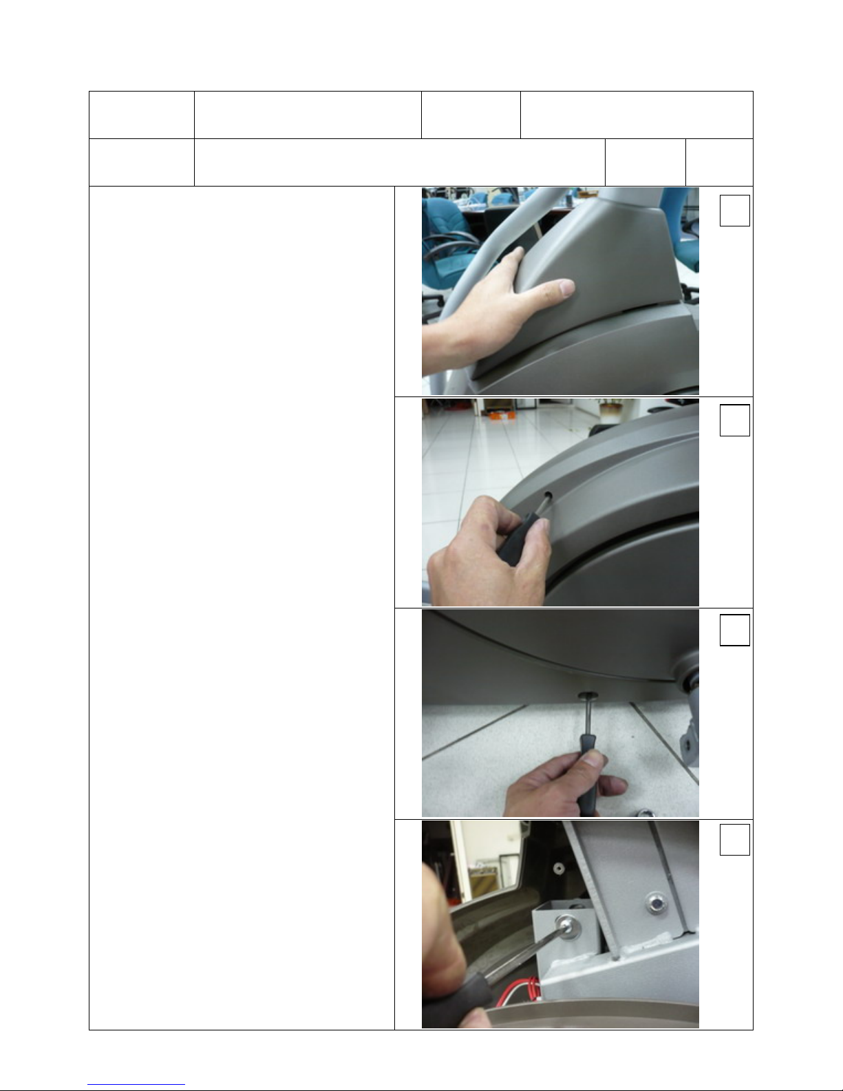
Procedures:
1. Follow procedures 2 and 3 to release
Connecting Arm Assembly and Pedal
Arm Assembly.
2. Slightly press the Console Mast Cover
to take it apart from Side Cases, as
shown in figure 1.
3. Use Phillips head screwdriver to
release 7pcs of 4x19 self tapping
screws and 3pcs of 5x16 x 3 tapping
screws to take Right Side Case apart,
as shown in figures 2 and 3.
4. To take the Left Side Case apart,
release 4x15 self tapping screws with
1/4"x19 flat washers on the main
frame and 3pcs of 5x16 Tapping
Screws. Then disconnect two red
jumpers and white grounding
(remember to mark for red jumpers) to
release left Side Case, as shown in
figures 4, 5 and 6.
1
2
3
4
Model SE578SA Service Replacing Parts
Parts 4 Left and right Side Cases Rev.
Procedures:
5. To resume, connect the red jumpers
and the grounding back on the AC
Electronic Module.
6. Return Left Side Case (with one 5/16"
x 23 x 1.5T flat washer on it) onto the
main frame and use 4x15self tapping
screw with 1/4"x19 flat washer to hold
it (not too tight temporarily) then
tighten with 3pcs of 5x16 tapping
screws (make sure Side Case matches
with Round Disk). Tighten 4x15 self
tapping screws, as shown in figures 7
and 8.
7.
Match both Side Cases with each other
and use 7pcs of 4x19 self tapping
screws and 3pcs of 5x16 tapping
screws to secure them.
8. Reverse above procedures to resume
Pedal Arm and Connecting Arm.
5
6
7
8
Model SE578SA Service Replacing Parts
Parts 5 Cross Bar Assembly Rev.
Procedures:
1. Follow procedures 2, 3 and 4 to take
apart Connecting Arm, Pedal Arm and
both Side Cases.
2. Take off the Round Disk Cover by
using a tapering stick, as shown in
figure 1.
3. Use 12 mm wrench to release 5/16" x
15m/m hex head bolt with
5/16" x 35 x
1.5T flat washer and then use M6 and
13mm wrenches to release M8x40
socket head cap screws with M8x6.3T
nuts so that the both the Cross Bar and
Round Disk can be taken apart, as
shown in figures 2 and 3.
4. Use Phillips head screwdriver to
release 8pcs of 5x16 tapping screws
with 1/4"x19flat washers to separate
the Cross Bar from Round Disk Cover,
Crank, as shown in figure 4.
1
2
3
4
 Loading...