

Sole E35-2011, E25-2011 Owner’s Manual

FITNESS
PLEASE CAREFULLY READ THIS ENTIRE MANUAL BEFORE OPERATING YOUR NEW ELLIPTICAL

TABLEOF T TS
Product Registration
Important Safety Instructions
Important Electrical Information
Important Operation Instructions
Transport Instructions
E25 Assembly Instructions
E35 Assembly Instructions
Elliptical Features
Operation of Your New Elliptical
1
2
3
4
4
7
14
19
20
Programmable Features
Using Heart Rate Transmitter
General Maintenance
Manufacturer's Limited Warranty
ATTENTION
THIS ELLIPTICAL IS INTENDED FOR RESIDENTIAL USE ONLY AND ISWARRANTED FOR THE
APPLICATION. ANY OTHER APPLICATION VOIDS THIS WARRANTY IN ITS ENTIRETY.
24
30
32
33

FmTNES$
CONGRATULATIONS ON YOUR NEW ELLiPTiCAL AND WELCOME TO THE SOLE FAMILW
Thank you for your purchase of this quality elliptical trainer from SOLE. Your new elliptical has been
manufactured by one of the leading fitness manufacturers in the world and is backed by one of the
most comprehensive warranties available. SOLE will do all we can to make your ownership
experience as pleasant as possible for many years to come.
If you have any questions about your new product or questions about the warranty contact SOLE
Fitness at 1-866-780-SOLE (7653). If you have a technical problem with your new elliptical contact
SOLE technical service at 866-MYSOLE1 (697-6531).
Please take a moment at this time to record below the name of the dealer, their telephone number,
and the date of purchase for easy contact in the future. We appreciate your confidence in SOLE and
we will always remember that you are the reason that we are in business. Please complete and mail
your registration card today and enjoy your new elliptical.
Yours in Health,
SOLE Fitness
Name of Dealer
Telephone Number of Dealer
PRODUCT ST TI
RECORD YOUR SERIAL NUMBER
Please record the Serial Number of this fitness product
in the space provided below.
Serial Number
REGISTER YOUR PURCHASE
The self-addressed product registration card must be completed in full and returned to SOLE.
You can also go to www.soleelliptkals.com under the support tab to register online.
E25_E35_20111111
E25 / E35 ELLIPTICAL
IMPORTANT TYI UCT
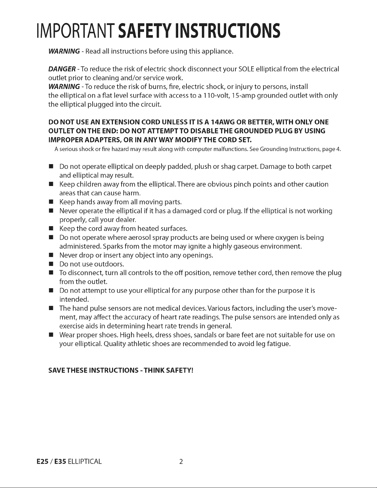
WARNING - Read all instructions before using this appliance.
DANGER -To reduce the risk of electric shock disconnect your SOLE elliptical from the electrical
outlet prior to cleaning and/or service work.
WARNING -To reduce the risk of burns, fire, electric shock, or injury to persons, install
the elliptical on a fiat level surface with access to a 110-volt, 15-amp grounded outlet with only
the elliptical plugged into the circuit.
DO NOT USE AN EXTENSION CORD UNLESS IT IS A 14AWG OR BETTER, WITH ONLY ONE
OUTLET ON THE END: DO NOT ATTEMPT TO DISABLE THE GROUNDED PLUG BY USING
IMPROPER ADAPTERS, OR IN ANYWAY MODIFY THE CORD SET.
A serious shock or fire hazard may result along with computer malfunctions. See Grounding Instructions, page 4.
[] Do not operate elliptical on deeply padded, plush or shag carpet. Damage to both carpet
and elliptical may result.
[] Keep children away from the elliptical.There are obvious pinch points and other caution
areas that can cause harm.
[] Keep hands away from all moving parts.
[] Never operate the elliptical if it has a damaged cord or plug. If the elliptical is not working
properly, call your dealer.
[] Keep the cord away from heated surfaces.
[] Do not operate where aerosol spray products are being used or where oxygen is being
administered. Sparks from the motor may ignite a highly gaseous environment.
[] Never drop or insert any object into any openings.
[] Do not use outdoors.
[] To disconnect, turn all controls to the off position, remove tether cord, then remove the plug
from the outlet.
[] Do not attempt to use your elliptical for any purpose other than for the purpose it is
intended.
[] The hand pulse sensors are not medical devices.Various factors, including the user's move-
ment, may affect the accuracy of heart rate readings.The pulse sensors are intended only as
exercise aids in determining heart rate trends in general.
[] Wear proper shoes. High heels, dress shoes, sandals or bare feet are not suitable for use on
your elliptical. Quality athletic shoes are recommended to avoid leg fatigue.
SAVE THESE INSTRUCTIONS =THINK SAFETY!
E25 / E35 ELLIPTICAL 2
IMPORTANTELECTCALl UCTI
WARNING!
NEVER remove any cover without first disconnecting AC power.
If voltage varies by ten percent (10%) or more, the performance of your elliptical may be
affected. Such conditions are not covered under your warranty. If you suspect the voltage is low,
contact your local power company or a licensed electrician for proper testing.
NEVER expose this elliptical to rain or moisture.This product is NOT designed for use outdoors,
near a pool or spa, or in any other high humidity environment.The operating temperature
specification is 40 to 120 degrees Fahrenheit, and humidity is 95% non-condensing
(no water drops forming on surfaces).
GROUNDINGINSTRUCTIONS
This product must be grounded. If the elliptical should malfunction or breakdown,
grounding provides a path of least resistance for electric current, reducing the risk of electric
shock.This product is equipped with a cord having an equipment-grounding plug.The plug
must be plugged into an appropriate outlet that is properly installed and grounded in
accordance with all local codes and ordinances.
DANGER - Improper connection of the equipment=grounding conductor cart result in a risk
of electric shock. Check with a qualified electrician or serviceman if you are in doubt as to
whether the product is properly grounded. Do not modify the plug provided with the
product if it will not fit the outlet; have a proper outlet installed by a qualified electrician.
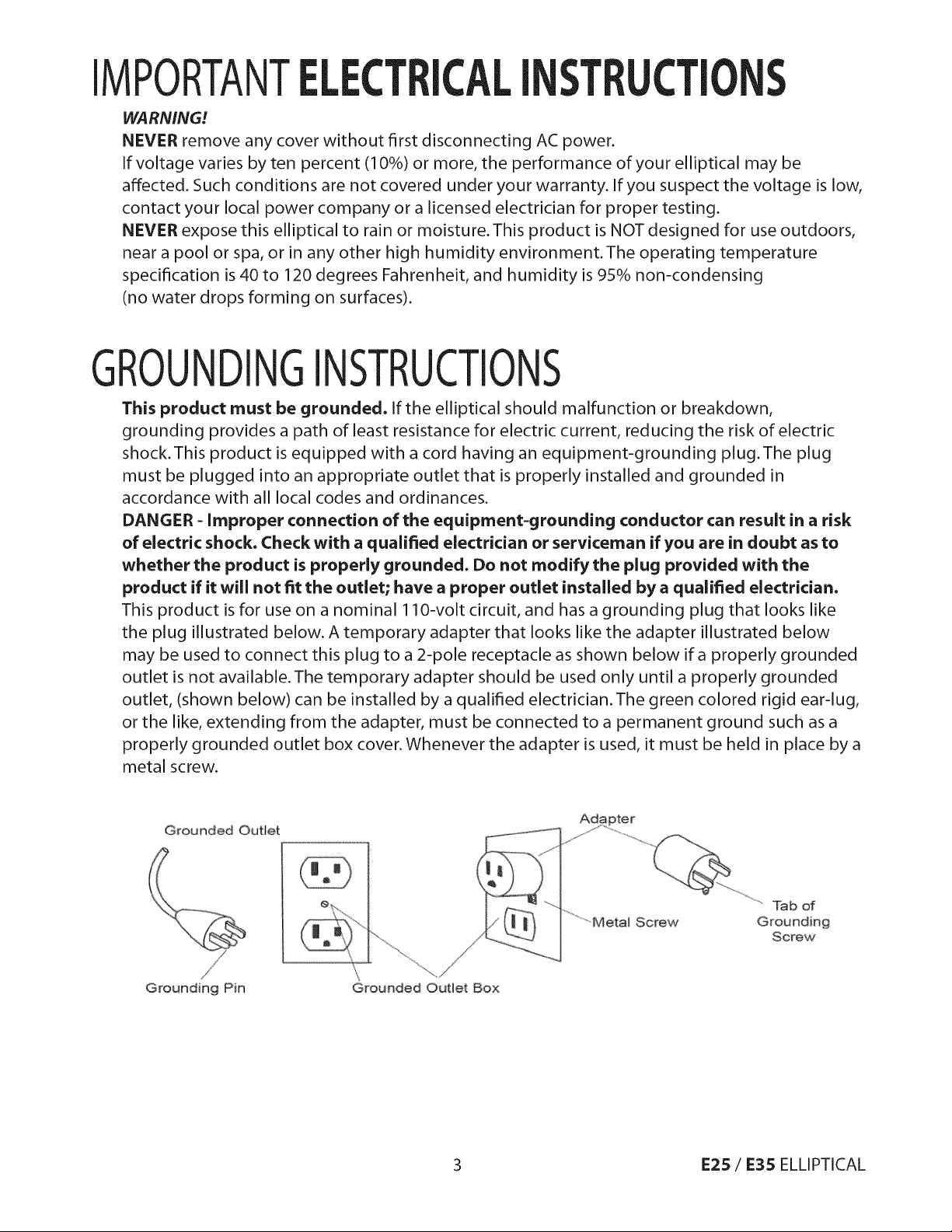
This product is for use on a nominal 1lO-volt circuit, and has a grounding plug that looks like
the plug illustrated below. A temporary adapter that looks like the adapter illustrated below
may be used to connect this plug to a 2-pole receptacle as shown below if a properly grounded
outlet is not available.The temporary adapter should be used only until a properly grounded
outlet, (shown below) can be installed by a qualified electrician.The green colored rigid ear-lug,
or the like, extending from the adapter, must be connected to a permanent ground such as a
properly grounded outlet box cover. Whenever the adapter is used, it must be held in place by a
metal screw.
Grounded Outlet
Grounding Pin
..........Tabof
Grounding
Screw
Grounded Outlet Box
3 E25 / E35 ELLIPTICAL
IMPORTANT T I ST
[] NEVER operate this elliptical without reading and completely understanding the results of
any operational change you request from the computer.
[] Understand that changes in speed and incline do not occur immediately. Set your desired
speed on the computer console and release the adjustment key.The computer will obey the
command gradually.
[] NEVER use your elliptical during an electrical storm. Surges may occur in your household
power supply that could damage elliptical components. Unplug the elliptical during an
electrical storm as a precaution.
[] Use caution while participating in other activities while walking on your elliptical; such as
watching television, reading, etc.These distractions may cause you to lose balance or stray
from walking in the center of the belt; which may result in serious injury.
[] Always hold on to a handrail or hand bar while making control changes (incline, speed, etc.).
[] Do not use excessive pressure on console control keys.They are precision set to function
properly with little finger pressure. Pushing harder is not going to make the unit go faster
or slower. If you feel the buttons are not functioning properly with normal pressure contact
your SOLE dealer.
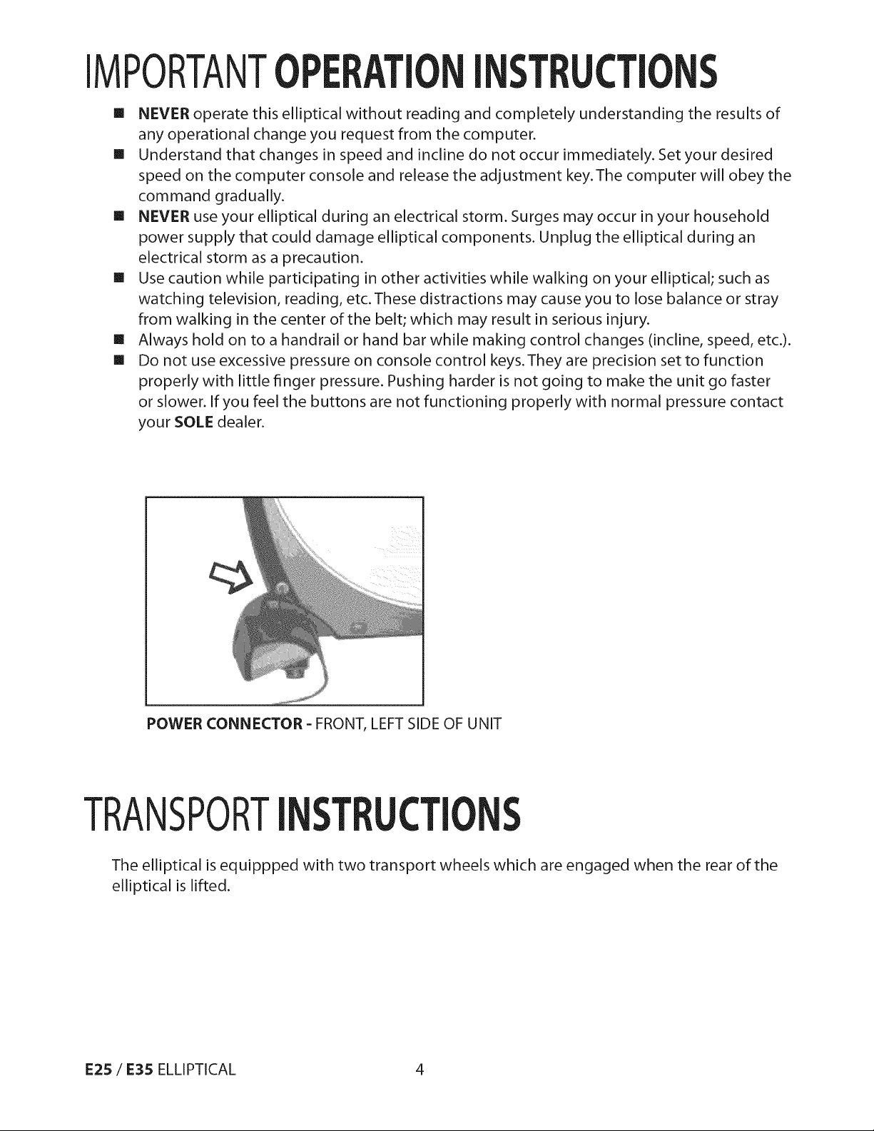
POWER CONNECTOR - FRONT, LEFT SIDE OF UNIT
TRANSPORTI ST T
The elliptical is equippped with two transport wheels which are engaged when the rear of the
elliptical is lifted.
E25 / E35 ELLIPTICAL 4
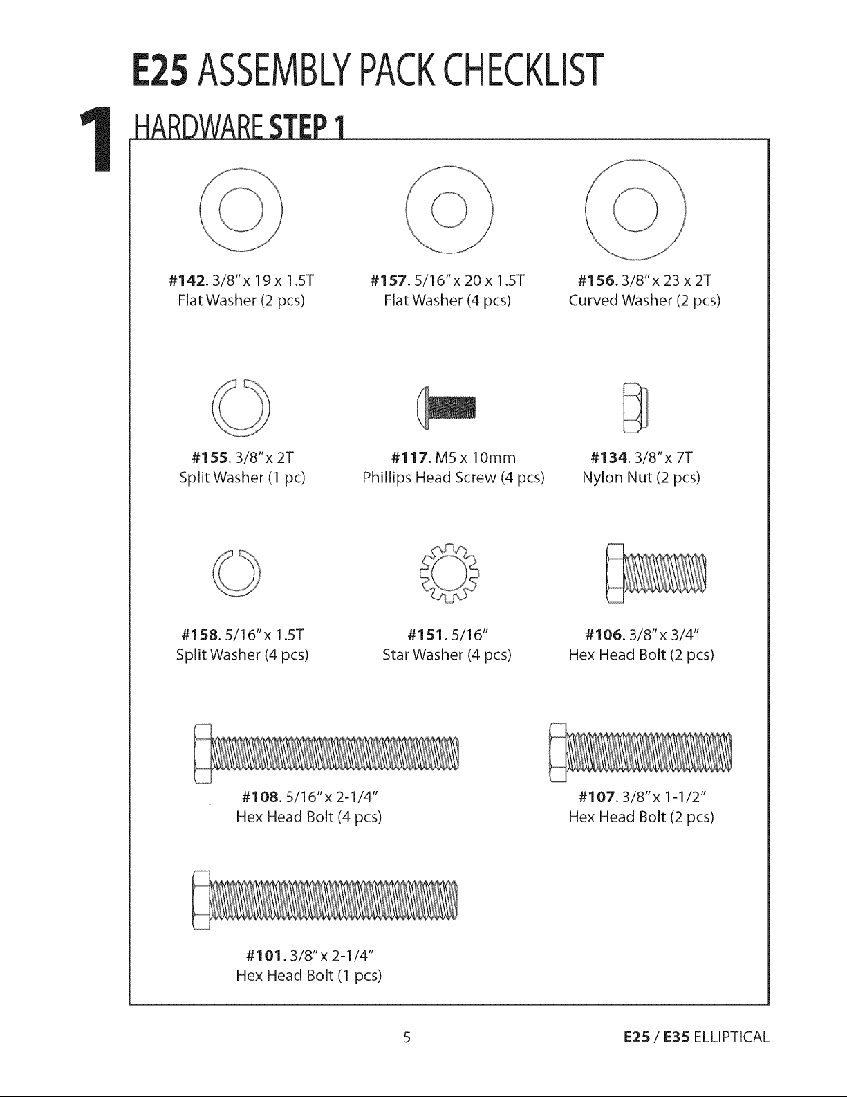
ASSEMBLYPACKCHECKLIST
#142.3/8" x 19 x 1.ST
Flat Washer (2 pcs)
#155.3/8"x 2T
Split Washer (1 pc)
#158.5/16"x 1.5T
Split Washer (4 pcs)
#157, 5/16"x 20 x 1.5T
Flat Washer (4 pcs)
#117. M5 x lOmm
Phillips Head Screw (4 pcs)
#151.5/16"
Star Washer (4 pcs)
#156.3/8" x 23 x 2T
Curved Washer (2 pcs)
#134.3/8" x 7T
Nylon Nut (2 pcs)
#106.3/8"x 3/4"
Hex Head Bolt (2 pcs)
#108.5/16"x 2-1/4"
Hex Head Bolt (4 pcs)
#101.3/8" x 2-1/4"
Hex Head Bolt (1 pcs)
#107.3/8"x 1-1/2"
Hex Head Bolt (2 pcs)
5 E25 / E35 ELLIPTICAL
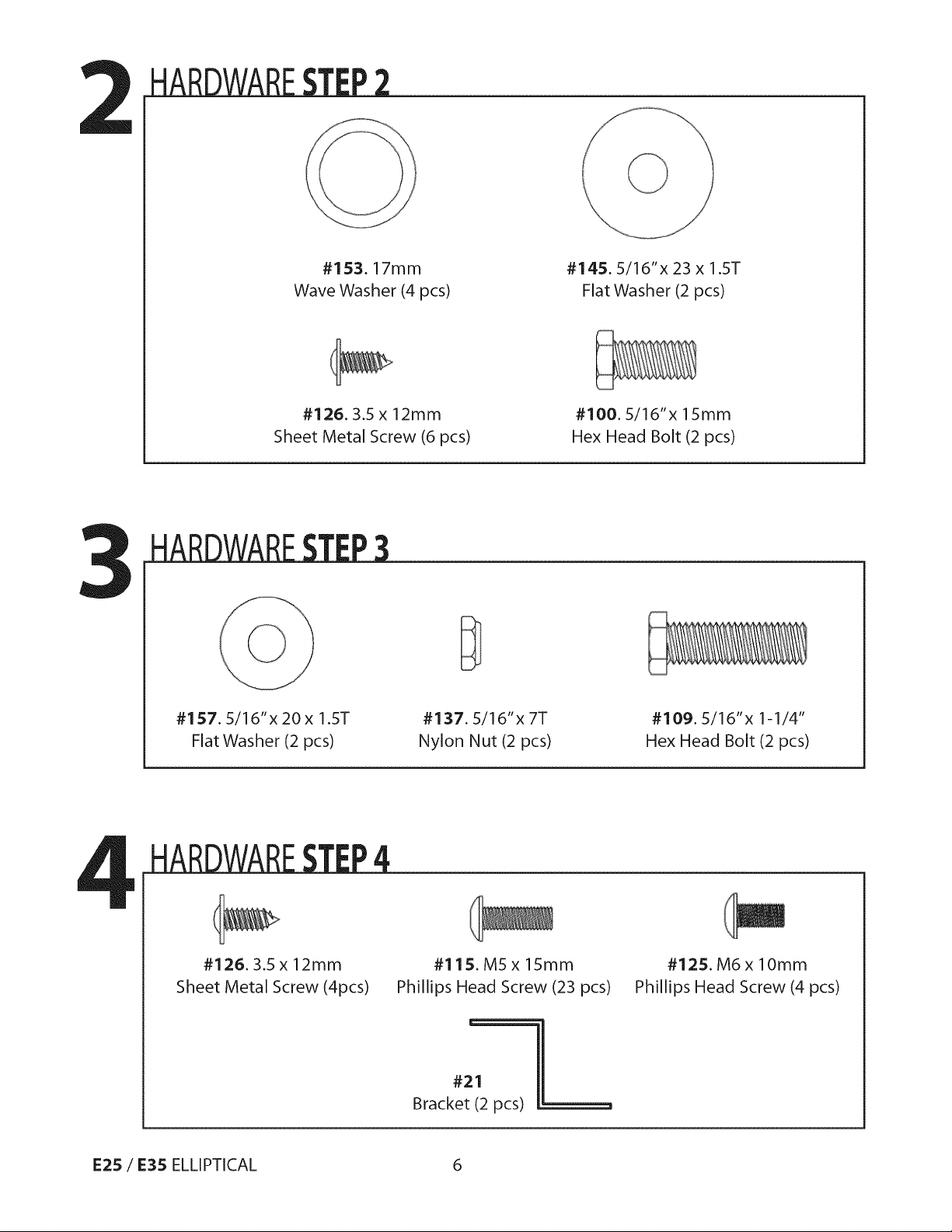
#153.17mm
Wave Washer (4 pcs)
#145.5/16"x 23 x 1.5T
Flat Washer (2 pcs)
#126.3.5 x 12mm
Sheet Metal Screw (6 pcs)
#157.5/16"x 20 x 1.5T
Flat Washer (2 pcs)
#137.5/16"x 7T
Nylon Nut (2 pcs)
#100.5/16"x 15mm
Hex Head Bolt (2 pcs)
#109.5/16"x 1-1/4"
Hex Head Bolt (2 pcs)
#126.3.5 x 12mm
Sheet Metal Screw (4pcs)
E25 / E35 ELLIPTICAL 6
#115. M5 x 15mm
Phillips Head Screw (23 pcs)
Bracket (2 pcs)
#125. M6 x 10mm
Phillips Head Screw (4 pcs)
#21
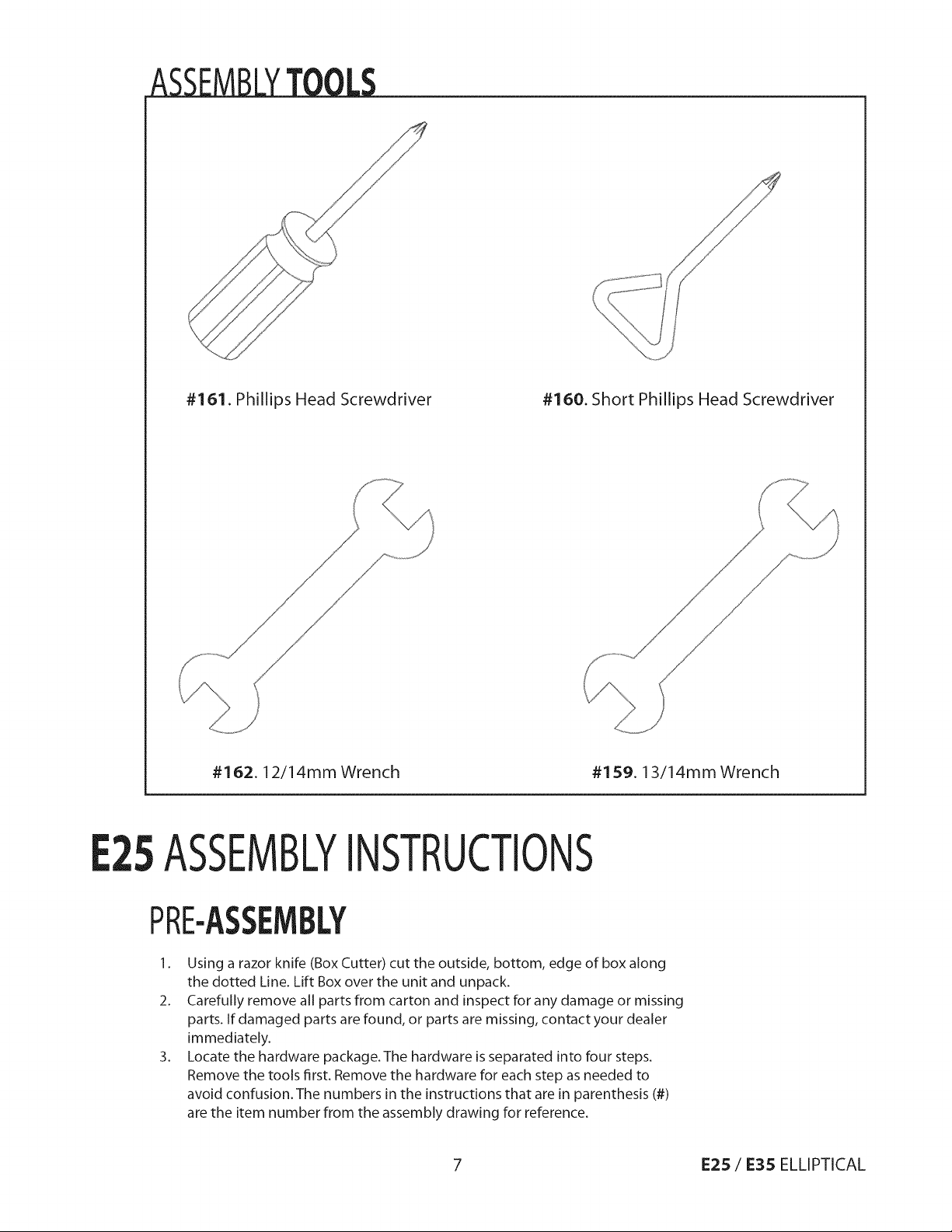
#161.PhillipsHeadScrewdriver #160.Short PhillipsHeadScrewdriver
#162.12/14mm Wrench #159. 13/14mmWrench
5ASSEMLYINSTRUCTIONS
PRE-ASSEMBLY
1. Using a razor knife (Box Cutter) cut the outside, bottom, edge of box along
the dotted Line. Lift Box over the unit and unpack.
2. Carefully remove all parts from carton and inspect for any damage or missing
parts. If damaged parts are found, or parts are missing, contact your dealer
immediately.
3. Locate the hardware package. The hardware is separated into four steps.
Remove the tools first. Remove the hardware for each step as needed to
avoid confusion. The numbers in the instructions that are in parenthesis (#)
are the item number from the assembly drawing for reference.
7 E25 / E35 ELLIPTICAL
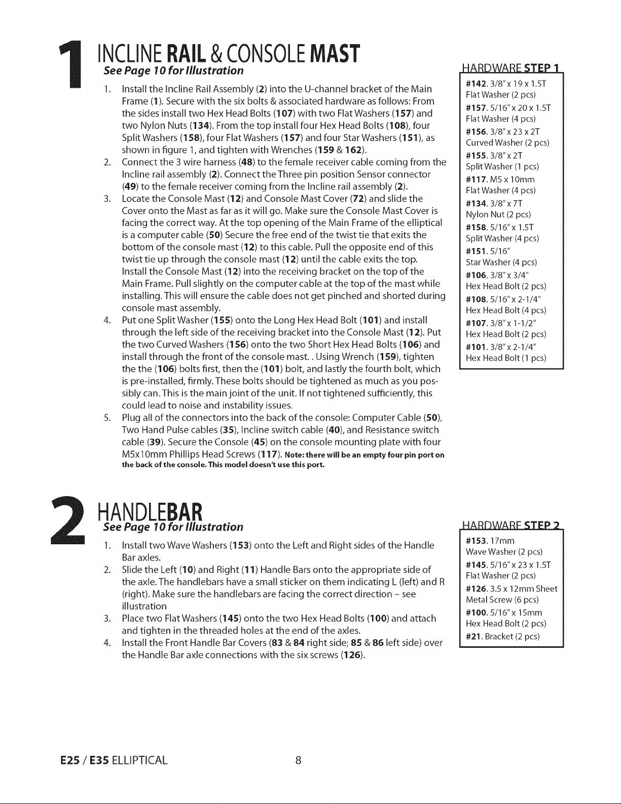
INCLINE &CONSOLE
See Page 10 for illustration
1. Install the Incline Rail Assembly (2) into the U-channel bracket of the Main
Frame (1). Secure with the six bolts & associated hardware as follows: From
the sides install two Hex Head Bolts (107) with two Flat Washers (157) and
two Nylon Nuts (134). From the top install four Hex Head Bolts (108), four
Split Washers (158), four Flat Washers (157) and four Star Washers (151), as
shown in figure 1, and tighten with Wrenches (159 & 162).
2. Connect the 3 wire harness (48) to the female receiver cable coming from the
Incline rail assembly (2). Connect the Three pin position Sensor connector
(49) to the female receiver coming from the Incline rail assembly (2).
3. Locate the Console Mast (12) and Console Mast Cover (72) and slide the
Cover onto the Mast as far as it will go. Make sure the Console Mast Cover is
facing the correct way. At the top opening of the Main Frame of the elliptical
is a computer cable (50) Secure the free end of the twist tie that exits the
bottom of the console mast (12) to this cable. Pull the opposite end of this
twist tie up through the console mast (12) until the cable exits the top.
Install the Console Mast (12) into the receiving bracket on the top of the
Main Frame. Pull slightly on the computer cable at the top of the mast while
installing. This will ensure the cable does not get pinched and shorted during
console mast assembly.
4. Put one Split Washer (155) onto the Long Hex Head Bolt (101) and install
through the left side of the receiving bracket into the Console Mast (12). Put
the two Curved Washers (156) onto the two Short Hex Head Bolts (106) and
install through the front of the console mast.. Using Wrench (159), tighten
the the (106) bolts first, then the (101) bolt, and lastly the fourth bolt, which
is pre-installed, firmly. These bolts should be tightened as much as you pos-
sibly can. This is the main joint of the unit. If not tightened sufficiently, this
could lead to noise and instability issues.
5. Plug all of the connectors into the back of the console: Computer Cable (50),
Two Hand Pulse cables (35), Incline switch cable (40), and Resistance switch
cable (39). Secure the Console (45) on the console mounting plate with four
MSxlOmm Phillips Head Screws (117). Note:there will be anemptyfour pin porton
the back of the console. This model doesn't use this port.
#142.3/8"x 19x 1.5T
FlatWasher (2 pcs)
#157.5/16"x 20 x 1.ST
FlatWasher (4 pcs)
#156. 3/8"x 23 x 2T
Curved Washer (2 pcs)
#155.3/8"x 2T
Split Washer (1 pcs)
#117. M5 x lOmm
FlatWasher (4 pcs)
#134. 3/8"x 7T
Nylon Nut (2 pcs)
#158. 5/16"x 1.5T
Split Washer (4 pcs)
#151.5/16"
StarWasher (4 pcs)
#106. 3/8"x 3/4"
Hex Head Bolt (2 pcs)
#108.5/16"x 2-1/4"
Hex Head Bolt (4 pcs)
#107.3/8"x 1-1/2"
Hex Head Bolt (2 pcs)
#101.3/8"x 2-1/4"
Hex Head Bolt (1 pcs)
HANDLE
See Page 10 for illustration
1. Install two Wave Washers (153) onto the Left and Right sides of the Handle
Bar axles.
2. Slide the Left (1O)and Right (11) Handle Bars onto the appropriate side of
the axle.The handlebars have a small sticker on them indicating L (left) and R
(right). Make sure the handlebars are facing the correct direction - see
illustration
3. Place two Flat Washers (145) onto the two Hex Head Bolts (100) and attach
and tighten in the threaded holes at the end of the axles.
4. Install the Front Handle Bar Covers (83 & 84 right side; 85 & 86 left side) over
the Handle Bar axle connections with the six screws (126).
E25 / E35 ELLIPTICAL 8
#153.17rnm
WaveWasher(2 pcs)
#145.5/16"x 23 x 1.ST
FlatWasher (2 pcs)
#126. 3.5 x 12mm Sheet
Metal Screw (6 pcs)
#100. 5/16"x 15rnm
Hex Head Bolt (2 pcs)
#21. Bracket (2 pcs)
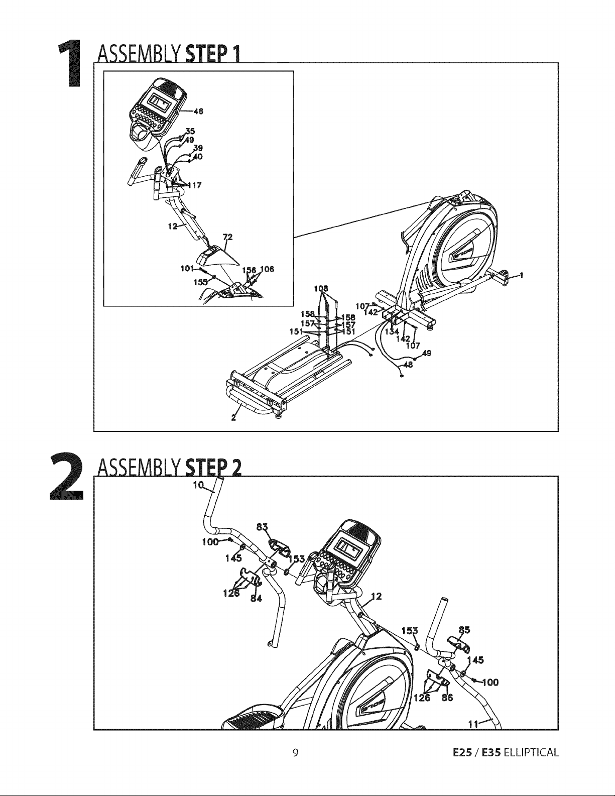
ASSEMBLYSTEP1
9 E25 / E35 ELLIPTICAL
 Loading...