

SOLE E25, E55 Owner's Manual

FmTNESS
OWNER'S MANUAL
PLEASE CAREFULLY READ THIS ENTIRE MANUAL BEFORE
OPERATING YOUR NEW ELLIPTICAL!
Product Registration ..................................................................................... 2
Important Safety Instructions ........................................................................... 3
Important Electrical Information ........................................................................ 4
Important Operation Instructions ....................................................................... 4
E25 Assembly Instructions ............................................................................... 5
E55 Assembly Instructions ............................................................................... 12
Operation of Your New Elliptical ........................................................................ 18
Manufacturer's Limited Warranty ....................................................................... 31
ATTENTION-THIS ELLIPTICAL IS INTENDED FOR RESIDENTIAL USE
ONLYAND IS WARRANTED FOR THATAPPLICATION. ANY OTHER
APPLICATION VOIDS THIS WARRANTY IN ITS ENTIRETY.
1 E25 / E55 Elliptical
L
FITNESS
CONGRATULATIONS ON YOUR
NEW ELLIPTICAL AND WELCOME
TO THE SOLE FAMIL W
Thank you for your purchase of this quality elliptical trainer from Sole. Your new
elliptical was manufactured by one of the leading fitness manufacturers in the world and
is backed by one of the most comprehensive warranties available. Sole will do all we
can to make your ownership experience as pleasant as possible for many years to
come.
If you have any questions about your new product or questions about the warranty
contact Sole Fitness at 1-866-780-7653.
Please take a moment at this time to record the name of the dealer, their telephone
number, and the date of purchase below to make any future, needed contact easy. We
appreciate your support and we will always remember that you are the reason that we
are in business. Please complete and mail your registration card today and enjoy your
new elliptical.
Yours in Health,
Sole Manufacturing, Inc.
Name of Dealer
Telephone Number of Dealer
Purchase Date
RECORD YOUR SERIAL NUMBER
Please record the Serial Number of this fitness product in the space provided below.
Serial Number
REGISTER YOUR PURCHASE
The self-addressed product registration card must be completed in full and returned to
Sole. or visit www.soletreadmills.com to register online.
2 E25 / E55 Elliptical
• Do not operate elliptical on deeply padded, plush or shag carpet. Damage to both
carpet and elliptical may result.
• Keep children away from the elliptical. There are obvious pinch points and other
caution areas that can cause harm.
• Keep hands away from all moving parts.
• Never operate the elliptical if it has a damaged cord or plug. If the elliptical is not
working properly, call your dealer.
• Keep the cord away from heated surfaces.
• Do not operate where aerosol spray products are being used or where oxygen is
being administered. Sparks from the motor may ignite a highly gaseous environment.
• Never drop or insert any object into any openings.
• Do not use outdoors.
• To disconnect, turn all controls to the off position, then remove the plug from the
outlet.
• Do not attempt to use your elliptical for any purpose other than for the purpose it is
intended.
• The hand pulse sensors are not medical devices. Various factors, including the user's
movement, may affect the accuracy of heart rate readings. The pulse sensors are
intended only as exercise aids in determining heart rate trends in general.
• Wear proper shoes. High heels, dress shoes, sandals or bare feet are not suitable
for use on your elliptical. Quality athletic shoes are recommended to avoid leg
fatigue.
SAVE THESE INSTRUCTIONS - THINK SAFETY!
3 E25 / E55 Elliptical
WARNING!
• NEVER remove any cover without first disconnecting AC power supply.
• If A.C. voltage varies by ten percent (10%) or more, the performance of your elliptical
may be affected. Such conditions are not covered under your warranty. If you
suspect the voltage is low, contact your local power company or a licensed electrician for
proper testing.
• NEVER expose this elliptical to rain or moisture. This product is NOT designed for
Use outdoors, near a pool or spa, or in any other high humidity environment.
• NEVER operate this elliptical without reading and completely understanding the
results of any operational change you request from the computer.
• Understand that changes in resistance do not occur immediately. Set your desired
level on the computer console and release the adjustment key. The computer will
obey the command gradually.
• NEVER use your elliptical during an electrical storm. Surges may occur in your
household power supply that could damage elliptical components.
• Use caution while participating in other activities while using your elliptical such as
watching television, reading, etc. These distractions may cause you to lose balance
which may result in serious injury.
• Always hold on to a handrail or hand bar while making control changes.
Do not use excessive pressure on console control keys. They are precision set to
properly function with little finger pressure. Pushing harder is not going to make the unit
go faster or slower. If you feel the buttons are not functioning properly with normal
pressure, contact your Sole dealer.
4 E25 / E55 Elliptical
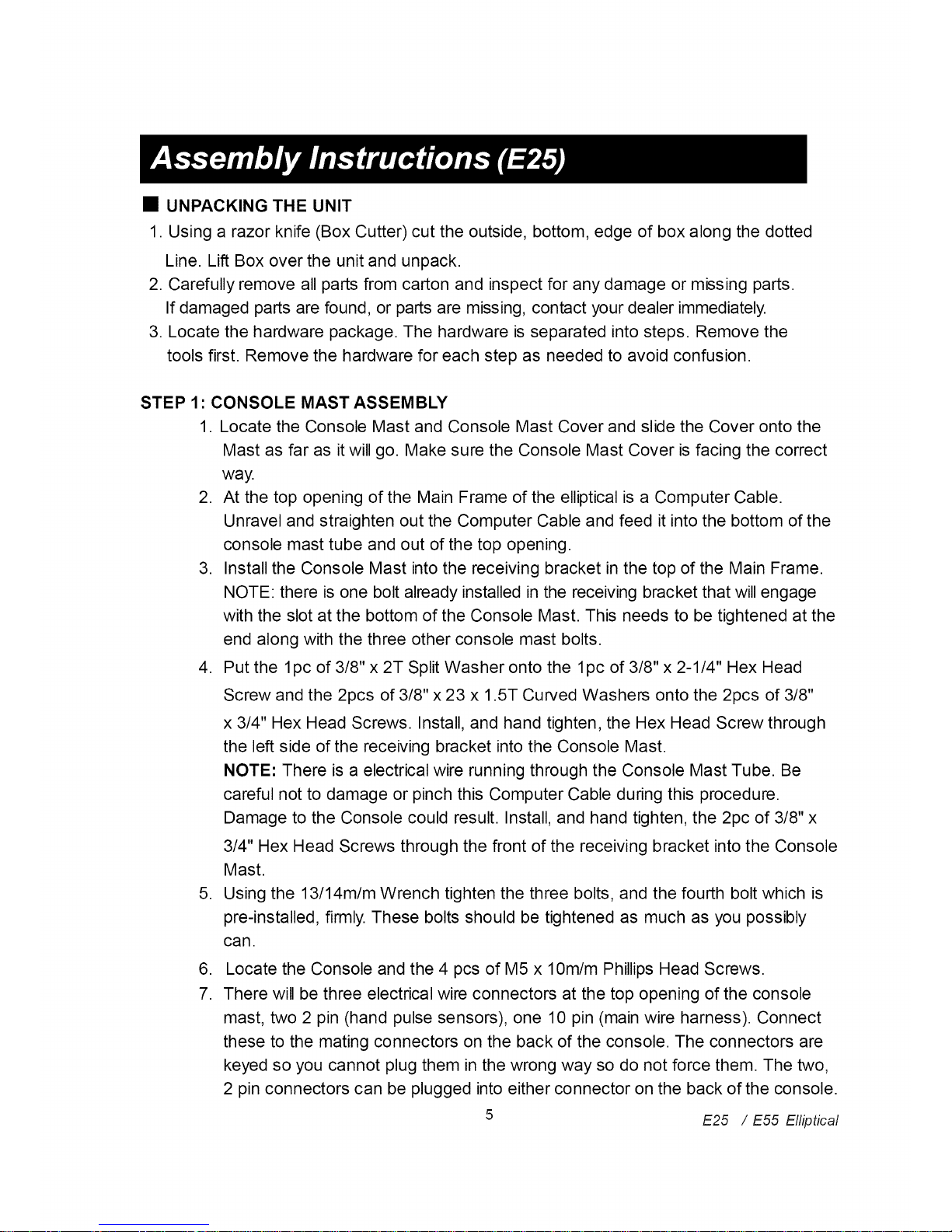
• UNPACKING THE UNIT
1. Using a razor knife (Box Cutter) cut the outside, bottom, edge of box along the dotted
Line. Lift Box over the unit and unpack.
2. Carefully remove all parts from carton and inspect for any damage or missing parts.
If damaged parts are found, or parts are missing, contact your dealer immediately.
3. Locate the hardware package. The hardware is separated into steps. Remove the
tools first. Remove the hardware for each step as needed to avoid confusion.
STEP 1: CONSOLE MAST ASSEMBLY
1. Locate the Console Mast and Console Mast Cover and slide the Cover onto the
Mast as far as it will go. Make sure the Console Mast Cover is facing the correct
way.
2. At the top opening of the Main Frame of the elliptical is a Computer Cable.
Unravel and straighten out the Computer Cable and feed it into the bottom of the
console mast tube and out of the top opening.
3. Install the Console Mast into the receiving bracket in the top of the Main Frame.
NOTE: there is one bolt already installed in the receiving bracket that will engage
with the slot at the bottom of the Console Mast. This needs to be tightened at the
end along with the three other console mast bolts.
4. Put the 1pc of 3/8" x 2T Split Washer onto the 1pc of 3/8" x 2-1/4" Hex Head
Screw and the 2pcs of 3/8" x 23 x 1.5T Curved Washers onto the 2pcs of 3/8"
x 3/4" Hex Head Screws. Install, and hand tighten, the Hex Head Screw through
the left side of the receiving bracket into the Console Mast.
NOTE: There is a electrical wire running through the Console Mast Tube. Be
careful not to damage or pinch this Computer Cable during this procedure.
Damage to the Console could result. Install, and hand tighten, the 2pc of 3/8" x
3/4" Hex Head Screws through the front of the receiving bracket into the Console
Mast.
5. Using the 13/14m/m Wrench tighten the three bolts, and the fourth bolt which is
pre-installed, firmly. These bolts should be tightened as much as you possibly
can.
,
7.
Locate the Console and the 4 pcs of M5 x 10m/m Phillips Head Screws.
There will be three electrical wire connectors at the top opening of the console
mast, two 2 pin (hand pulse sensors), one 10 pin (main wire harness). Connect
these to the mating connectors on the back of the console. The connectors are
keyed so you cannot plug them in the wrong way so do not force them. The two,
2 pin connectors can be plugged into either connector on the back of the console.
5 E25 / E55 Elliptical
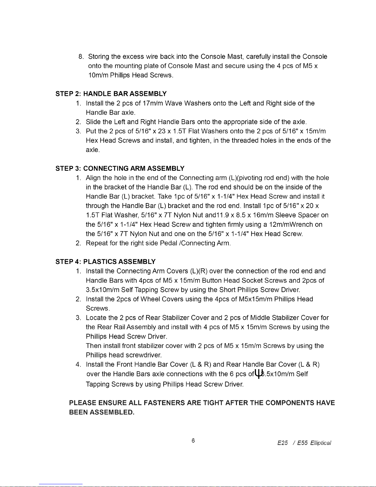
.
Storing the excess wire back into the Console Mast, carefully install the Console
onto the mounting plate of Console Mast and secure using the 4 pcs of M5 x
lOm/m Phillips Head Screws.
STEP 2: HANDLE BAR ASSEMBLY
1. Install the 2 pcs of 17m/m Wave Washers onto the Left and Right side of the
Handle Bar axle.
2. Slide the Left and Right Handle Bars onto the appropriate side of the axle.
3. Put the 2 pcs of 5/16" x 23 x 1.5T Flat Washers onto the 2 pcs of 5/16" x 15m/m
Hex Head Screws and install, and tighten, in the threaded holes in the ends of the
axle.
STEP 3: CONNECTING ARM ASSEMBLY
1. Align the hole in the end of the Connecting arm (L)(pivoting rod end) with the hole
in the bracket of the Handle Bar (L). The rod end should be on the inside of the
Handle Bar (L) bracket. Take 1pc of 5/16" x 1-1/4" Hex Head Screw and install it
through the Handle Bar (L) bracket and the rod end. Install 1pc of 5/16" x 20 x
1.5T Flat Washer, 5/16" x 7T Nylon Nut and11.9 x 8.5 x 16m/m Sleeve Spacer on
the 5/16" x 1-1/4" Hex Head Screw and tighten firmly using a 12m/mWrench on
the 5/16" x 7T Nylon Nut and one on the 5/16" x 1-1/4" Hex Head Screw.
2. Repeat for the right side Pedal/Connecting Arm.
STEP 4: PLASTICS ASSEMBLY
1. Install the Connecting Arm Covers (L)(R) over the connection of the rod end and
Handle Bars with 4pcs of M5 x 15m/m Button Head Socket Screws and 2pcs of
3.5xl0m/m Self Tapping Screw by using the Short Phillips Screw Driver.
2. Install the 2pcs of Wheel Covers using the 4pcs of M5x15m/m Phillips Head
Screws.
3. Locate the 2 pcs of Rear Stabilizer Cover and 2 pcs of Middle Stabilizer Cover for
the Rear Rail Assembly and install with 4 pcs of M5 x 15m/m Screws by using the
Phillips Head Screw Driver.
Then install front stabilizer cover with 2 pcs of M5 x 15m/m Screws by using the
Phillips head screwdriver.
4. Install the Front Handle Bar Cover (L & R) and Rear Handle Bar Cover (L & R)
the Handle Bars axle connections with the 6 pcs of L_.5xlom/m self
over
Tapping Screws by using Phillips Head Screw Driver.
PLEASE ENSURE ALL FASTENERS ARE TIGHT AFTER THE COMPONENTS HAVE
BEEN ASSEMBLED,
6 E25 / E55 Elliptical
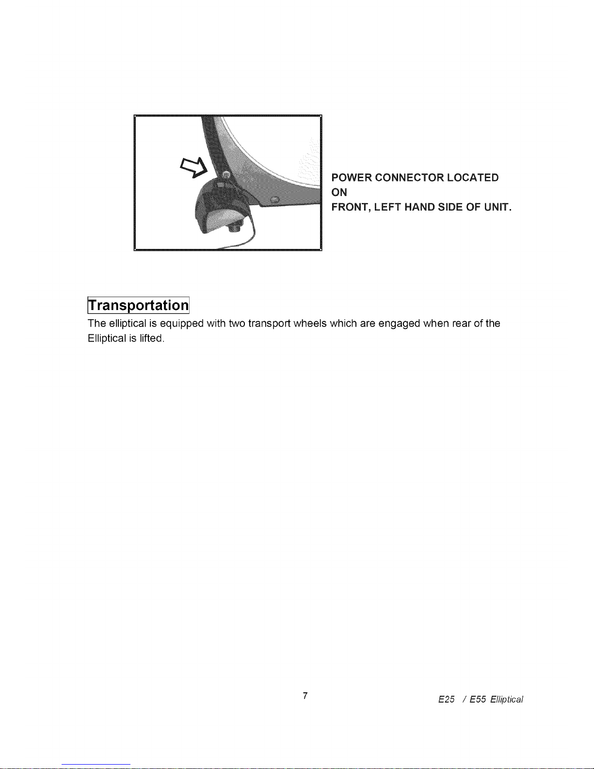
POWER CONNECTOR LOCATED
ON
FRONT, LEFT HAND SIDE OF UNIT,
Fransportation
The elliptical is equipped with two transport wheels which are engaged when rear of the
Elliptical is lifted.
7 E25 / E55 Elliptical
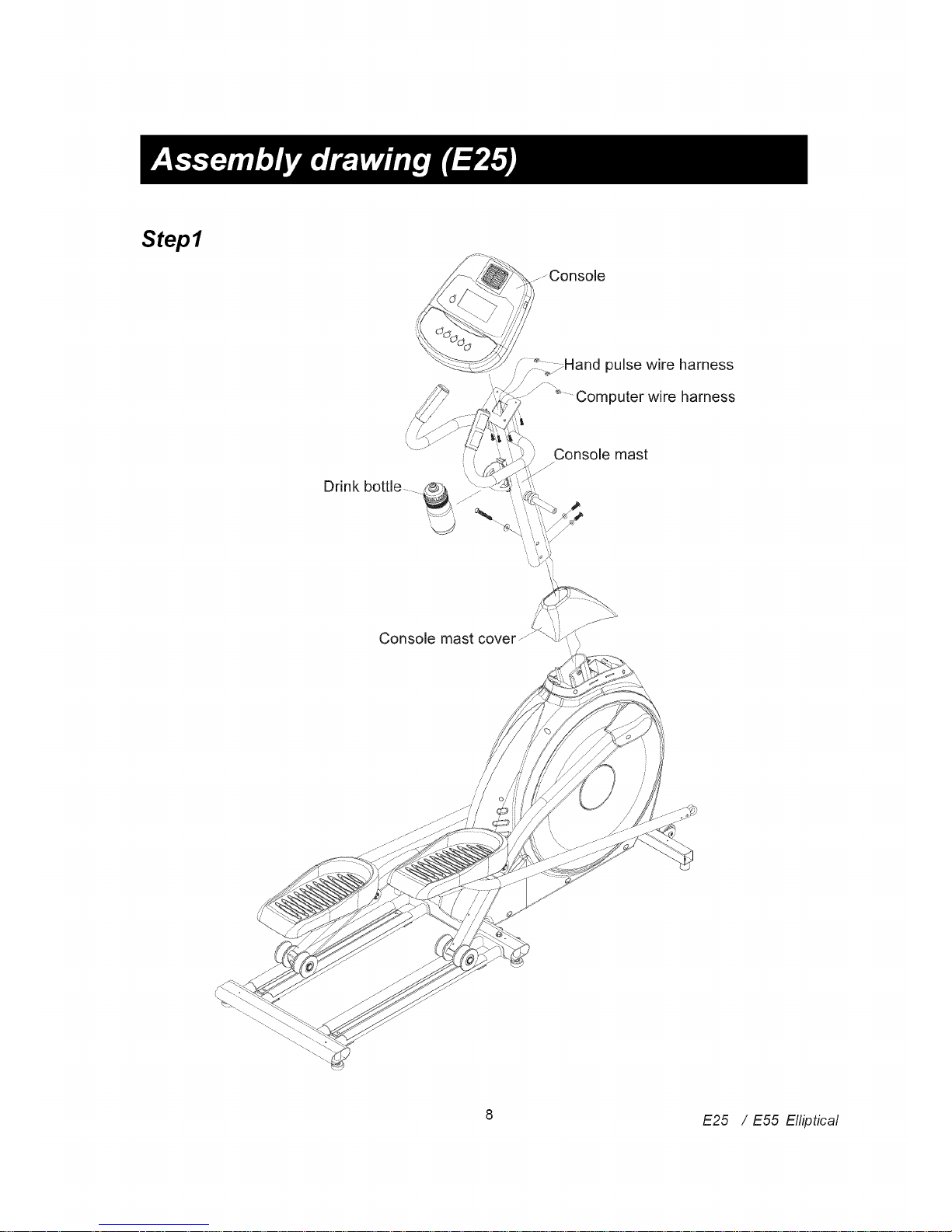
Step1
Drink bottle
_,_.---Console
/ _Hand pulse wire harness
/ -
Computer wire harness
Console mast
Console mast cover
8 E25 / E55 Elliptical
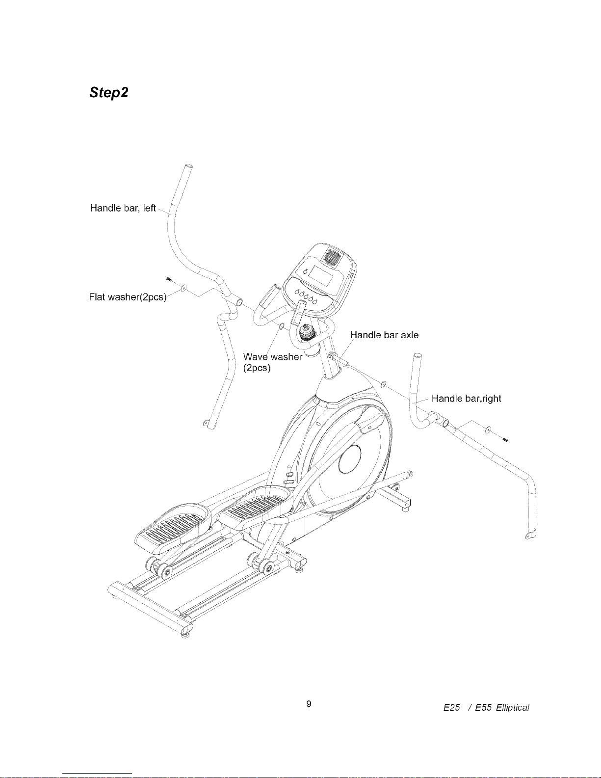
Step2
//// ////
i /
//' //'
/' //
Handle bar, left-../ '
Flat washer(2pcs)
i )
,/_- ]'
//
//
//
Wave
(2pcs)
/
//
Handle bar axle
/
/
i f
Handle bar, right
E ,,,,
If
9 E25 / E55 Elliptical
 Loading...