

SOLE E20 Owner's Manual

- SOL0032 -
OWNER’S MANUAL
PLEASE CAREFULLY READ THIS ENTIRE MANUAL BEFORE
OPERATING YOUR NEW ELLIPTICAL!

1
TABLE OF
CONTENTS
Important Safety Instructions 3
Important Electrical Instructions 4
Important Operation Instructions 4
Assembly Instructions 7
Operation of Your Console 11
General Maintenance 19
Exploded View Diagram 20
Parts List 21
Manufacturer’s Limited Warranty 24
ATTENTION
THIS ELLIPTICAL IS INTENDED FOR RESIDENTIAL USE ONLY AND IS WARRANTED FOR THIS APPLICATION. ANY
OTHER APPLICATION VOIDS THIS WARRANTY IN ITS ENTIRETY.
SOL0032_Ver.A

2
Congratulations on your new elliptical and welcome to the SOLE family!
Thank you for your purchase of this quality elliptical from SOLE Manufacturing, Inc. Your new elliptical was
manufactured by one of the leading fitness manufacturers in the world and is backed by one of the most
comprehensive warranties available. Through your dealer, SOLE will do all we can to make your ownership
experience as pleasant as possible for many years to come. If not purchased direct from SOLE, the local
dealership where you purchased this elliptical is your administrator for all SOLE warranty and service needs.
Their responsibility is to provide you with the technical knowledge and service personnel to make your
experience more informed and any difficulties easier to remedy.
Please take a moment at this time to record the name of the dealer, their telephone number, and the date of
purchase below to make any future, needed contact easy. We appreciate your support and we will always
remember that you are the reason that we are in business.
Please keep a copy of your purchase receipt with this manual.
Yours in Health,
BOYLES FITNESS Equipment Pty Ltd.
Name of Dealer______________________________________
Purchase Date_______________________________________

3
IMPORTANT
SAFETY
INSTRUCTIONS
When using an electrical appliance, basic precautions should always be followed, including the following:
Read all instructions before using this appliance.
DANGER
- To reduce the risk of electric shock:
1. Always unplug this appliance from the electrical outlet immediately after using and before cleaning.
WARNING
- To reduce the risk of burns, fire, electric shock, or injury to persons:
1. An appliance should never be left unattended when plugged in. Unplug from outlet when not in use, and before
putting on or taking off parts.
2. Do not operate under blanket or pillow. Excessive heating can occur and cause fire, electric shock, or injury to persons.
3. Close supervision is necessary when this appliance is used by, on, or near children, or disabled persons.
4. Use this appliance only for its intended use as described in this manual. Do not use attachments not
recommended by the manufacturer.
5. Never operate this appliance if it has a damaged cord or plug, if it is not working properly, if it has been dropped or
damaged, or dropped into water. Return the appliance to a service center for examination and repair.
6. Do not carry this appliance by supply cord or use cord as a handle.
7. Keep the cord away from heated surfaces.
8. Never operate the appliance with the air openings blocked. Keep the air openings free of lint, hair, and the like.
9. Never drop or insert any object into any opening.
10. Do not use outdoors.
11. Do not operate where aerosol (spray) products are being used or where oxygen is being administered.
12. The appliance is intended for household use.
13. This appliance is not intended for use by persons with reduced physical, sensory or mental capabilities, or lack
of experience and knowledge, unless they have been given supervision or instruction concerning use of the
appliance by a person responsible for their safety. Keep children under the age of 13 away from this machine.
Fitness Equipment Safety Instructions
To disconnect, turn all controls to the off position, then remove the plug from the outlet.
Do not operate equipment on deeply padded, plush or shag carpet. Damage to both carpet and equipment may
result. Before beginning this or any exercise program, consult a physician. This is especially important for persons
over the age of 35 or persons with pre-existing health conditions.
Keep hands away from all moving parts.
The pulse sensors are not medical devices. Various factors, including the user’s movement, may affect the accuracy of
heart rate readings. The pulse sensors are intended only as exercise aids in determining heart rate trends in general.
Do not attempt to use your equipment for any purpose other than for the purpose it is intended.
Wear proper shoes. High heels, dress shoes, sandals or bare feet are not suitable for use on your equipment. Quality
athletic shoes are recommended to avoid leg fatigue.
Failure to follow all guidelines may compromise the effectiveness of the exercise experience, expose
yourself (and possibly others) to injury, and reduce the longevity of the equipment.
SAVE THESE INSTRUCTIONS - THINK SAFETY!

4
IMPORTANT
ELECTRICAL
INSTRUCTIONS
WARNING!
• NEVER remove any cover without first disconnecting AC power supply.
• If A.C. voltage varies by ten percent (10%) or more, the performance of
your elliptical may be affected. Such conditions are not covered under
your warranty. If you suspect the voltage is low, contact your local power
company or a licensed electrician for proper testing.
• NEVER expose this elliptical to rain or moisture. This product is NOT designed for use outdoors, near a pool or spa, or in any other high
humidity environment. Maximum environmental ratings are 5 to 40
degrees Celsius, and humidity is 95% non-condensing (no water drops
forming on surfaces).
Plug-In
IMPORTANT
OPERATION INSTRUCTIONS
NEVER operate this elliptical without reading and completely understanding the results of any
operational change you request from the computer.
Understand that changes in resistance do not occur immediately. Set your desired level on the
computer console and release the adjustment key. The computer will obey the command
gradually.
NEVER use your elliptical during an electrical storm. Surges may occur in your household
power supply that could damage elliptical components.
Use caution while participating in other activities while using your elliptical such as watching
television, reading, etc. These distractions may cause you to lose balance, resulting in serious
injury.
Always hold on to a handlebar while making control changes.
TRANSPORTATION
The elliptical is equipped with transport wheels, which are engaged when the rear of the
elliptical is lifted.
EXITING DISPLAY MODE
This product is preset to a DISPLAY MODE that keeps the console continually powered on. To turn this
feature off and allow your display to go into DISPLAY MODE when not being used, please use the following procedure:
1. When in stand-by status, hold Start, Stop and Enter keys for five seconds to enter the Engineering
Mode.
2. Use the
/
keys to choose SELECT FUNCTION, then press the Enter key.
3. Use the
/
keys to select the DISPLAY MODE, then press Enter key.
4. Use the
/
keys to turn ON or OFF the DISPLAY MODE function.
5. Hold the Stop key to save and exit Engineering Mode.
5
ASSEMBLY PACK
CHECKLIST
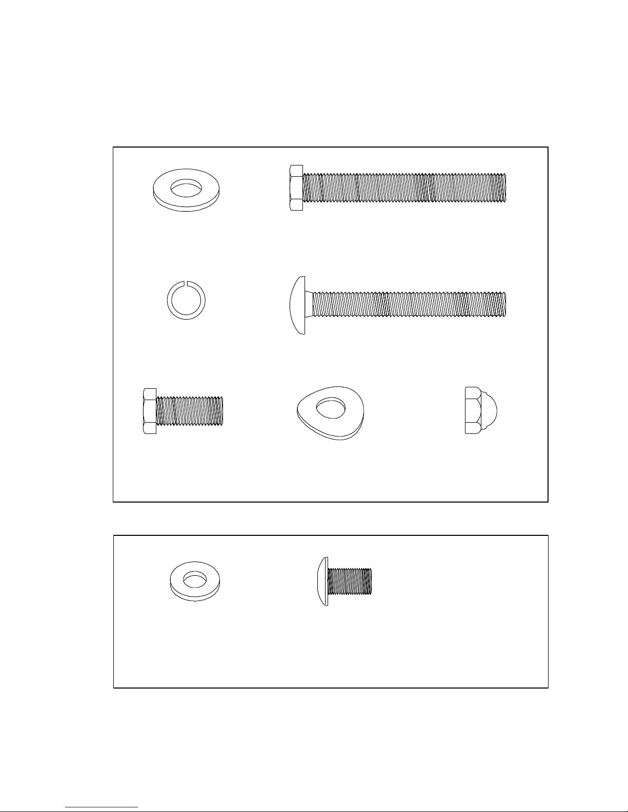
HARDWARE
STEP 1
#94. 3/8” Flat
Washer (2 pcs)
#120. 3/8” Split
Washer
(4 pcs)
#119. 3/8” x 3”
Hex Head Bolt (3 pcs)
#148. 3/8” x 3”
Carriage Bolt
(2 pcs)
#121. 3/8” x 3/4”
Hex Head Bolt
(1 pc)
HARDWARE
STEP 2
#149. 3/8” Curved
Washer (4 pcs)
#150. 3/8” Cap
Nut (2 pcs)
#147. 5/16” Flat
Washer
(2 pcs)
#151. 5/16”
Button Head Socket Bolt
(2 pcs)
6
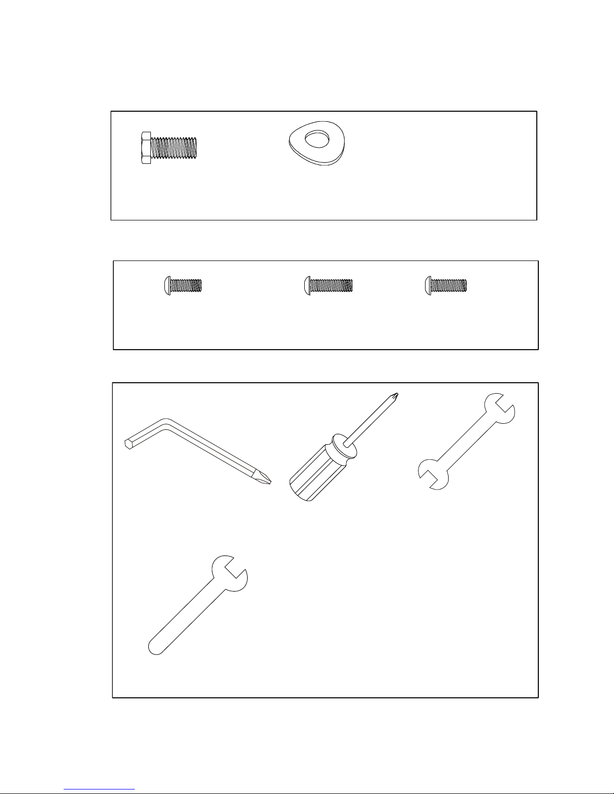
HARDWARE
STEP 3
#70. 5/16”
Hex Head Bolt
(6 pcs)
HARDWARE
STEP
4
#102. 5/16” Curved
Washer (6 pcs)
#78. M5 x 10mm
Phillips Head Screw
(4 pcs)
ASSEMBLY
TOOLS
#79.M5 x 15mm
Philips Head Screw
(8 pcs)
#108. M5 Allen Wrench /
Phillips Head Screw Driver
#110. Phillips Head
Screw Driver
#111.12.14mm Wrench
#113.12mm Wrench
#68-3.M5 x 12mm
Philips Head Screw(2 pcs)
7
1
ASSEMBLY
INSTRUCTIONS
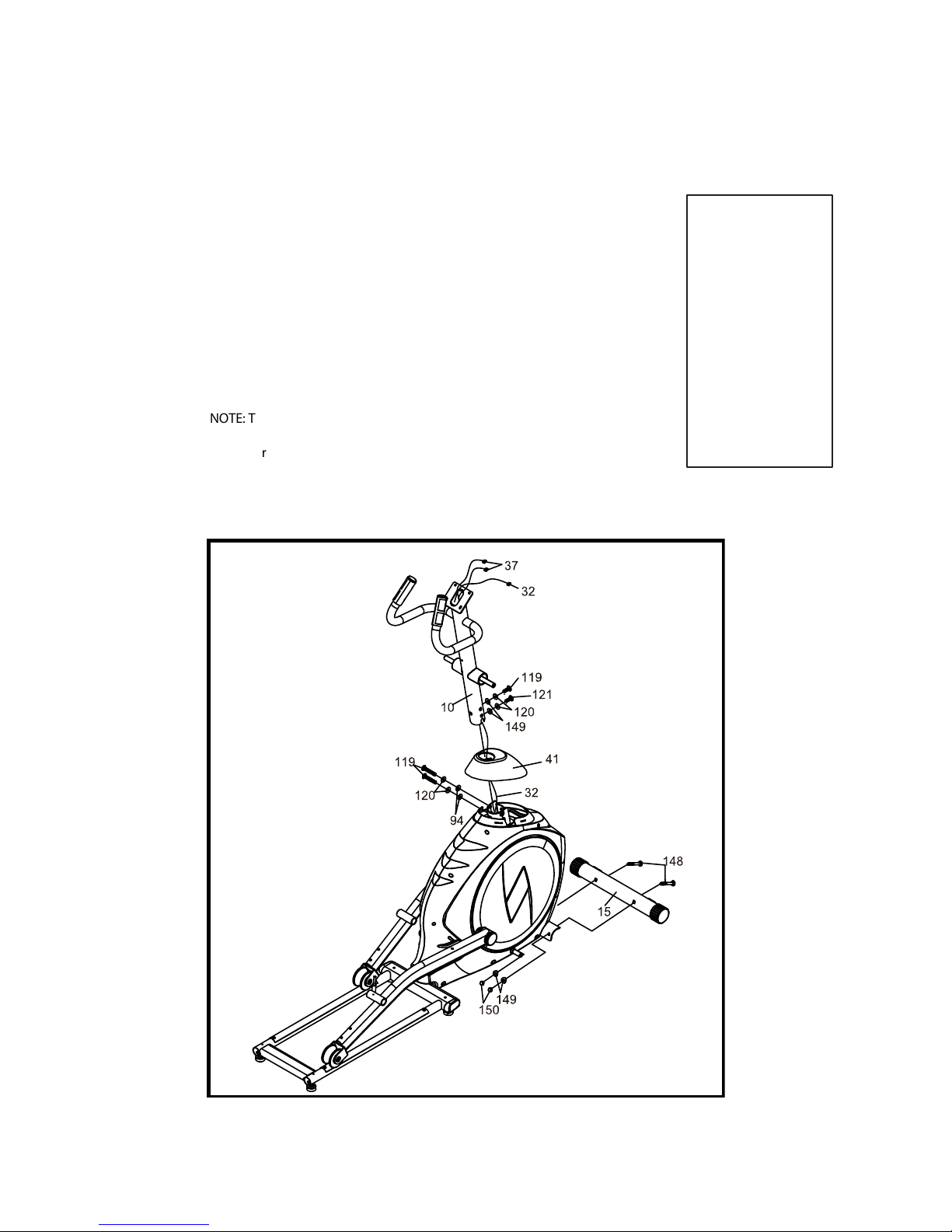
CONSOLE MAST & CONSOLE
1. Locate the Console Mast (10) and Console Mast Cover (41) and slide the
Cover onto the Mast as far as it will go. Make sure the Console Mast Cover
(41) is facing the correct way.
2. At the top opening of the Main Frame (1) of the elliptical is a Computer Cable
(32). Unravel and straighten out the Computer Cable (32) and feed it into the
bottom of the Console Mast tube (10) and out of the top opening.
3. Install the Console Mast (10) into the receiving bracket in the top of the Main
Frame (1) Put the two Split Washers (120) and two Curved Washers (149)
onto the one Hex Head Bolt (119) and one Hex Head Bolt (121) then install
the screw at the front of the Console Mast. Put two Flat Washers (94) , two
Split Washers (120) onto the two Hex Head Bolts (119). Install and tighten by
using the 12.14m/m Wrench (111).
NOTE: There is an electrical wire running through the Console Mast Tube (10).
Be careful not to damage or pinch this Computer Cable (32) during this
procedure.
4. Install the Front Stabilizer(15) on the front stabilizer holding plate at the
bottom of the main frame with the transportation wheels facing forward and
secure them with two Carriage Bolts (148), two Curved Washers(149) and
two Cap Nuts (150) by using 12.14m/m Wrench(111).
Hardware Step 1
#94. 3/8” Flat
Washer (2 pcs)
#119. 3/8” x 3”
Hex Head Bolt (3 pcs)
#120. 3/8” Split Washer
(4 pcs)
#121. 3/8” x 3/4”
Hex Head Bolt (1 pc)
#148. 3/8” x 3”
Carriage Bolt (2 pcs)
#149. 3/8” Curved
Washer (4 pcs)
#150. 3/8” Cap
Nut (2 pcs)
8
2
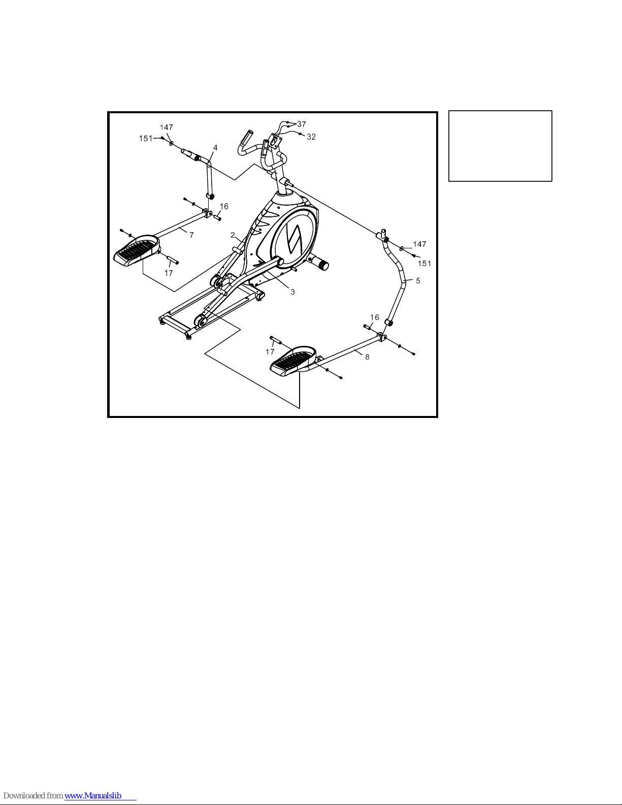
SWING ARMS
Hardware Step 2
#147. 5/16” Flat
Washer (2 pcs)
#151. 5/16” Button Head
Socket Bolt (2 pcs)
1. Slide the left and right Lower Swing Arms (4 & 5) onto the axle of the Mast and
secure with two 5/16” Button Head Socket Bolts (151) and two Flat Washers (147)
by using Combination M5 Allen Wrench & Phillips Head Screw Driver (108).
2. Remove the Pedal Axle (17) from left Pedal Arm (2) and install left Connecting
Arm (7) onto left Pedal Arm. Reinstall the Axle and the screw and tighten with
12mm and 14mm open end wrench. Repeat the same procedure again for the
right Connecting Arm (8) and Pedal Arm (3).
3. Remove the axles (16) which are on left and right connecting arms (7 & 8).
Connect the left and right connecting arm (7 & 8) with left and right lower handle
bar (4 & 5) and reinstall the axles (16) and the screw and tighten with the Wrench
(111).
151
147
5
8
16
17
147
151
16
17
7 2
3
32
37
4
 Loading...