

125-1-S150, 125-1-S200, 150-1-S200, 150-1-S230, 150-2-S150, 200-1-S200, 200-1-S230, 200-1-S260, 200-2-S200, 300-2-S200, 300-2-S230
SOLE 125-1-S150, 125-1-S200, 150-1-S200, 150-1-S230, 150-2-S150, 200-1-S200, 200-1-S230, 200-1-S260, 200-2-S200, 300-2-S200, 300-2-S230 Installation & User Manual
GB
INSTALLATION
&
USERS MANUAL
DOMESTIC SOLAR WATER HEATER
THERMOSIPHON SYSTEM
CLOSED CIRCUIT
MODELS EUROSTAR ECO :
125-1-S150, 125-1-S200, 150-1-S200, 150-1-S230, 150-2-S150, 200-1-S200, 200-1-S230, 200-1-S260, 200-2-S200, 300-2-S200, 300-2-S230

1
INDEX
INDEX .............................................................................................................................................................................. 1
1. Observance of the instructions and standards........................................................................................................... 2
2. Description of solar system and components ............................................................................................................ 2
2.1 General Description.................................................................................................................................................. 2
2.2. Collector................................................................................................................................................................... 3
2.3. Accumulation tank (cylinder)................................................................................................................................... 3
2.4 Support system......................................................................................................................................................... 4
2.5. Thermo convention liquid ....................................................................................................................................... 6
2.6. Packaging, Transport and Storage........................................................................................................................... 6
3. Warnings..................................................................................................................................................................... 7
4. Recommendations...................................................................................................................................................... 6
5. Flat Roof.................................................................................................................................................................... 15
Assembly instructions for systems with 1 collector: .................................................................................................... 15
Models: 125-1-S150, 125-1-S200, 150-1-S200, 150-1-S230, 200-1-S200, 200-1-S230, 200-1-S260............................ 15
Assembly instructions for systems with 2 collectors:................................................................................................... 17
Models: 150-2-S150, 200-2-S200, 300-2-S200, 300-2-S230.........................................................................................17
7. Inclined roof - Tiles ................................................................................................................................................... 19
Assembly instructions for systems with 1 collector : ................................................................................................... 19
Models: 125-1-S150, 125-1-S200, 150-1-S200, 150-1-S230, 200-1-S200, 200-1-S230, 200-1-S260............................ 19
Assembly instructions for systems with 2 collectors:................................................................................................... 21
Models: 150-2-S150, 200-2-S200, 300-2-S200, 300-2-S230.........................................................................................21
9. Check list for installer ............................................................................................................................................... 23
10. Operation instructions............................................................................................................................................ 24
11. Maintenance instructions.......................................................................................................................................24
12. Decommissioning of the system…………………..………………………….. …………………………..…………………….……………….….24

2
1. Observance of the instructions and standards.
1.1. It is very important to follow these installation, operating and maintenance instructions, in order to avoid
danger of death, injury, property damages, and to have your device functioning properly in the long run. The company
that manufactured and/or supplied this solar system has no liability for the installer and/or the user in case these
instructions have not been followed carefully.
1.2. Whether further information or clarifications are needed, please contact the supplier of the product.
1.3. These solar systems have been manufactured and tested under the European standards:
ISO 9806:2013: Energy – Solar Thermal Collectors – Test methods
EN 12975-1: Thermal solar systems and components – Solar collectors -part 1: General requirements.
EN 12975-2: Thermal solar systems and components – Solar collectors – part 2 : Test methods.
EN 12976-1: Thermal solar systems and components – Factory made systems - part 1: General
requirements.
EN 12976-2: Thermal solar systems and components – Factory made systems – part 2: Test methods.
1.4. These systems are in conformity with the applicable requirements of the following documents:
Ref. No.
Title
EN 60335-1:2012 +A11:2014
(IEC 60335-1:2010)
Household and similar electrical appliances — Safety —
Part 1: General requirement
EN 60335-2-21:2003 +A2:2008
(IEC 60335-2-21:2002 +A2:2008)
Household and similar electrical appliances — Safety —
Part 2-21: Particular requirements for storage water heaters
EN 60529:1991 +Α1:2000 +Α2:2013
(IEC 60529:1989 +Α1:1999 +Α2:2013)
Degrees of protection provided by enclosures (IP code)
ENV 61024-1:1995
(IEC 61024-1:1990)
Protection of structures against lightning
Part 1: General principles
The manufacturer declares that the equipment named in this document have been designed to comply with the
relevant sections of the above referenced specifications.
2. Description of solar system and components
2.1 General Description
This solar system is a closed loop thermosiphon unit which delivers hot water for domestic use. It consists
from the collector, the accumulation tank, the support system, the hydraulic accessories and the thermoconvention liquid.
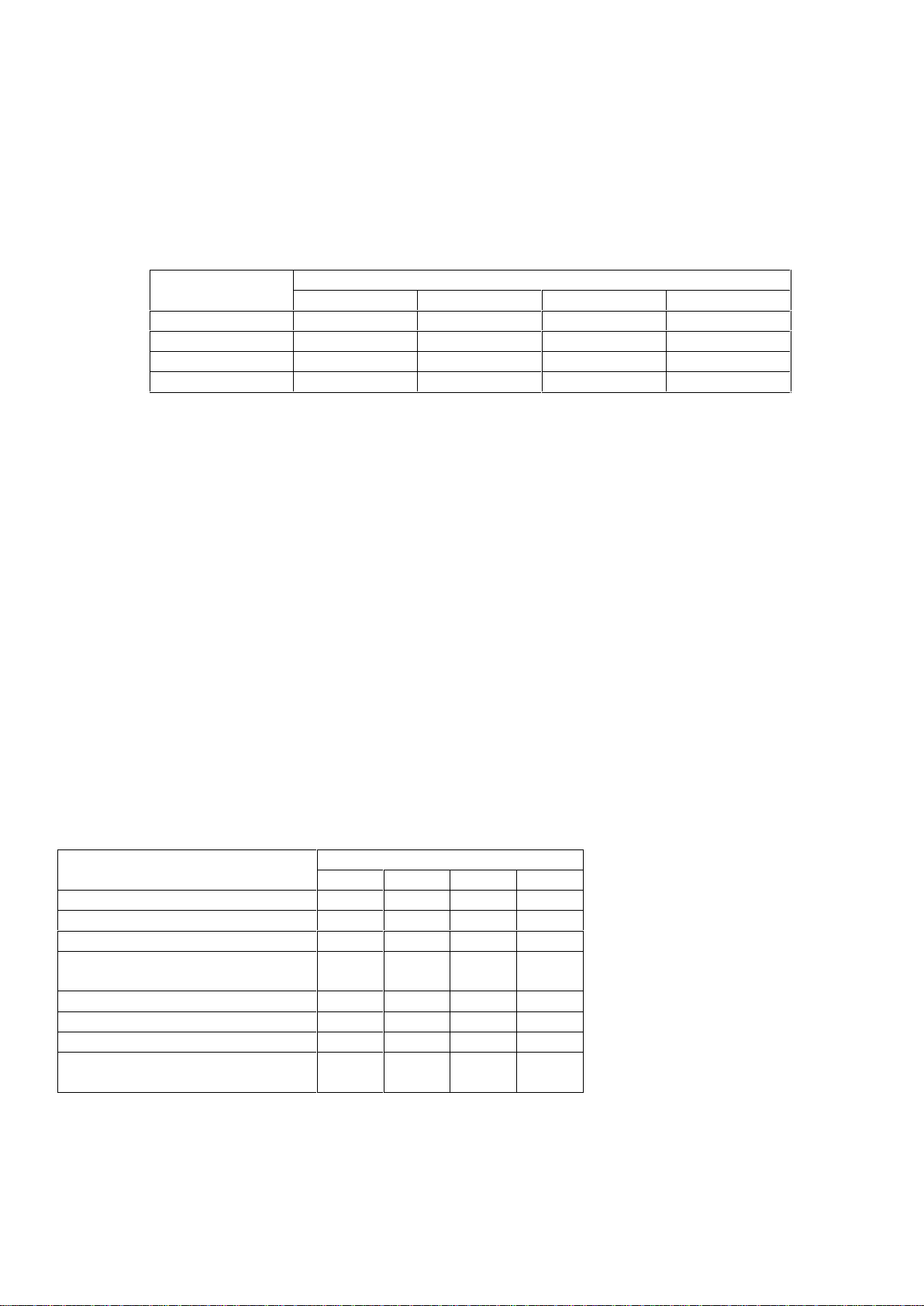
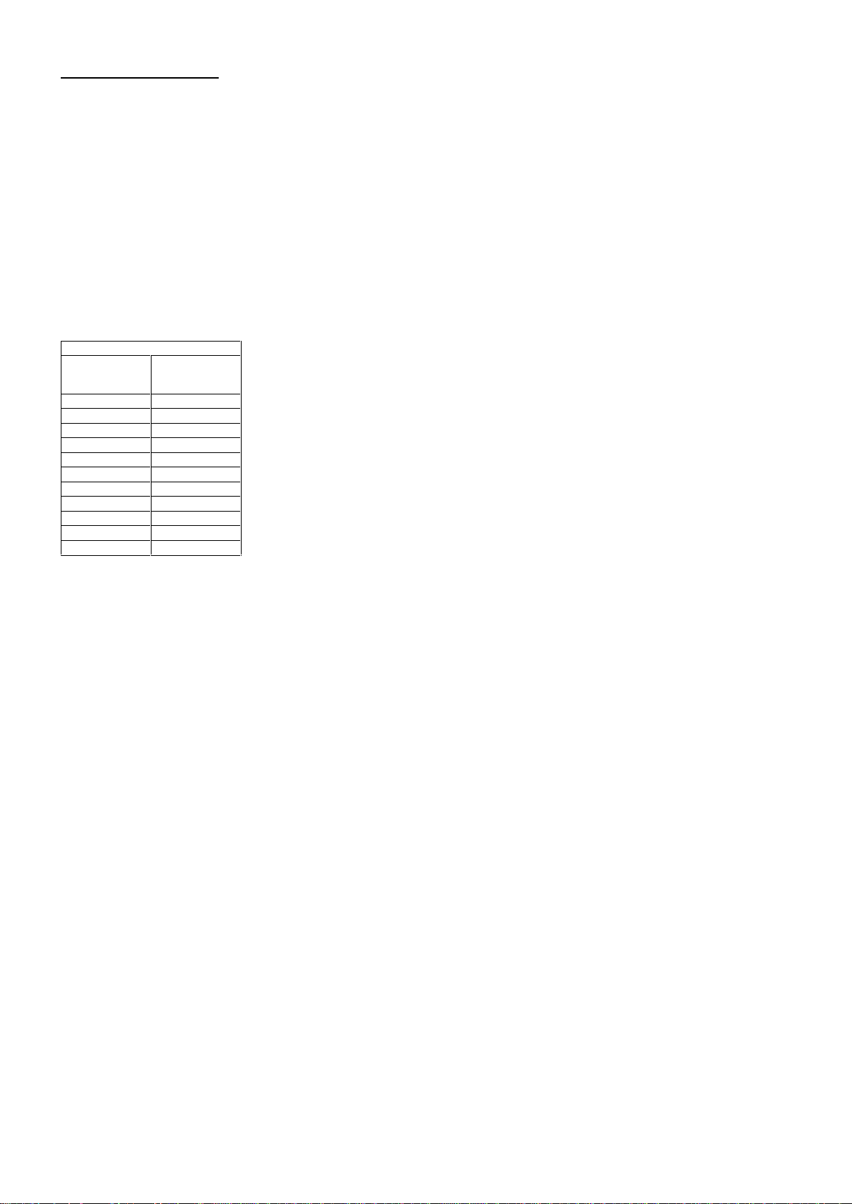
Four nominal sizes of accumulation tanks are combined with four different sizes of collectors as the table
below:
MODEL
TANK NOMINAL SIZES
COLLECTOR NOMINAL
SIZES
125 ltrs
150 ltrs
200 ltrs
300 ltrs
1,50m
2
2,00m
2
2,30m
2
2,60m
2
125-1-150
1
1
125-1-200
1
1
150-1-200
1
1
150-1-230
1
1
150-2-150
1
2
200-1-200
1
1
200-1-230
1
1
200-1-260
1
1
200-2-200
1
2
300-2-200
12300-2-230
1
2
Other combinations are available upon request
3
2.2. Collector
The collectors are manufactured in 4 sizes with nominal area of 1,50m2-2, 00m2-2.30m2-2,60m2. The
absorbers of the collectors are made by copper tubes and the fins area by selective aluminum fins. The fins
are welded to the tubes by laser welding. The frame of the collector is made by extruded aluminum epoxy
oven painted to resist ambient conditions.
The glass cover is a “prismatic securit” glass of 3.2mm thickness for maximum penetration of solar
irradiation. At the back and sides of the absorber there is sufficient insulation of rock wool and glass wool to
minimize heat loses and to resist stagnation temperatures.
Technical data of collector as the table below:
Nominal size (m2)
1,50
2,00
2,30
2,60
Length (mm)
1540
1960
1960
2135
Width (mm)
960
960
1165
1238
Depth (mm)
818181
81
Weight (kg)
27,3
32,0
38,8
44
Stagnation temperature: about 150oC
Test pressure: 1500 kPa
Operating pressure: 1000 kPa
2.3. Accumulation tank (cylinder)
The solar accumulation tank is an indirect (double circuit) hot water horizontal cylinder. The inner surface is
enameled at 850oC to guarantee potable sanitary water for long life. Additionally it is protected against
rusting with a large magnesium anode.
The ecologic polyurethane foam insulation guaranties minimum thermal loses even at very low ambient
temperatures. The external cover of the tank can resist any extreme weather conditions for life. The internal
heat exchanger with large surface guaranties the energy transfer to the domestic hot water.
The hot water exits from the hottest zone (level) of the tank. At the same time equal quantity of cold water
enters the tank at the coldest zone (level). The solar tank can be optionally (accessory) equipped with
immersion electric heater (electric element) for use only for emergency situations. The immersion electric
heater is available in 2 kW or 3kW or 4 kW at 230 Volt. It is equipped with control thermostat set at 60oC and
safety thermostat (thermal cut out) manually reset.
The safety valve only opens to discharge when the system pressure exceeds 10bar in the form of water.
Technical Data of tanks as table below:
Nominal size
125
150
200
300
Length (mm)
1130
1185
1215
1915
Diameter (mm)
440
500
530
530
Weight (kg)
35
46,7
50,8
83
Capacity (ltr)
(Incl. h.exchanger)
115
142
170
276
Test pressure (kPa)
1500
1500
1500
1500
Operating pressure (kPa)
1000
1000
1000
1000
Max temperature (oC)
90oC
90oC
90oC
90oC
Cold & hot water connectors
(male)
½˝½˝½˝
½˝
4
2.4 Support system
The support system is made from galvanized pressed steel. It is designed for flat roof installation as well as
for inclined tiled roof. It can be installed at 3 different inclinations. 20o-30o-40o, so it can meet any roof slope.
The support system can withstand wind velocity up to 97,2 km/hr. and weight of snow up to 64cm height.
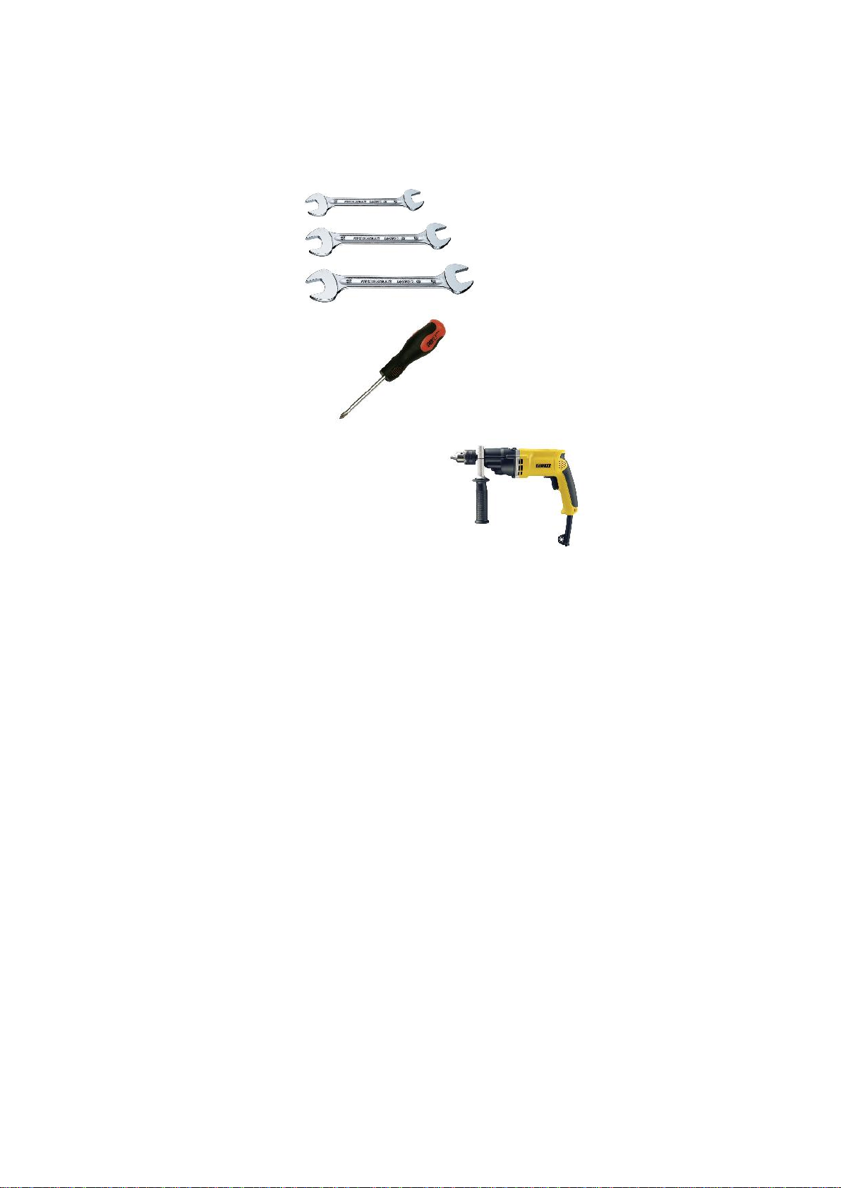
In order to assembly the support system the following tools are needed.
Spanner 10mm 1 X
Spanner 13mm 1 X
2 Spanners 17mm 2 X
Screwdriver 1 X
Drill Ø10 (for fastening the system on the roof)
5
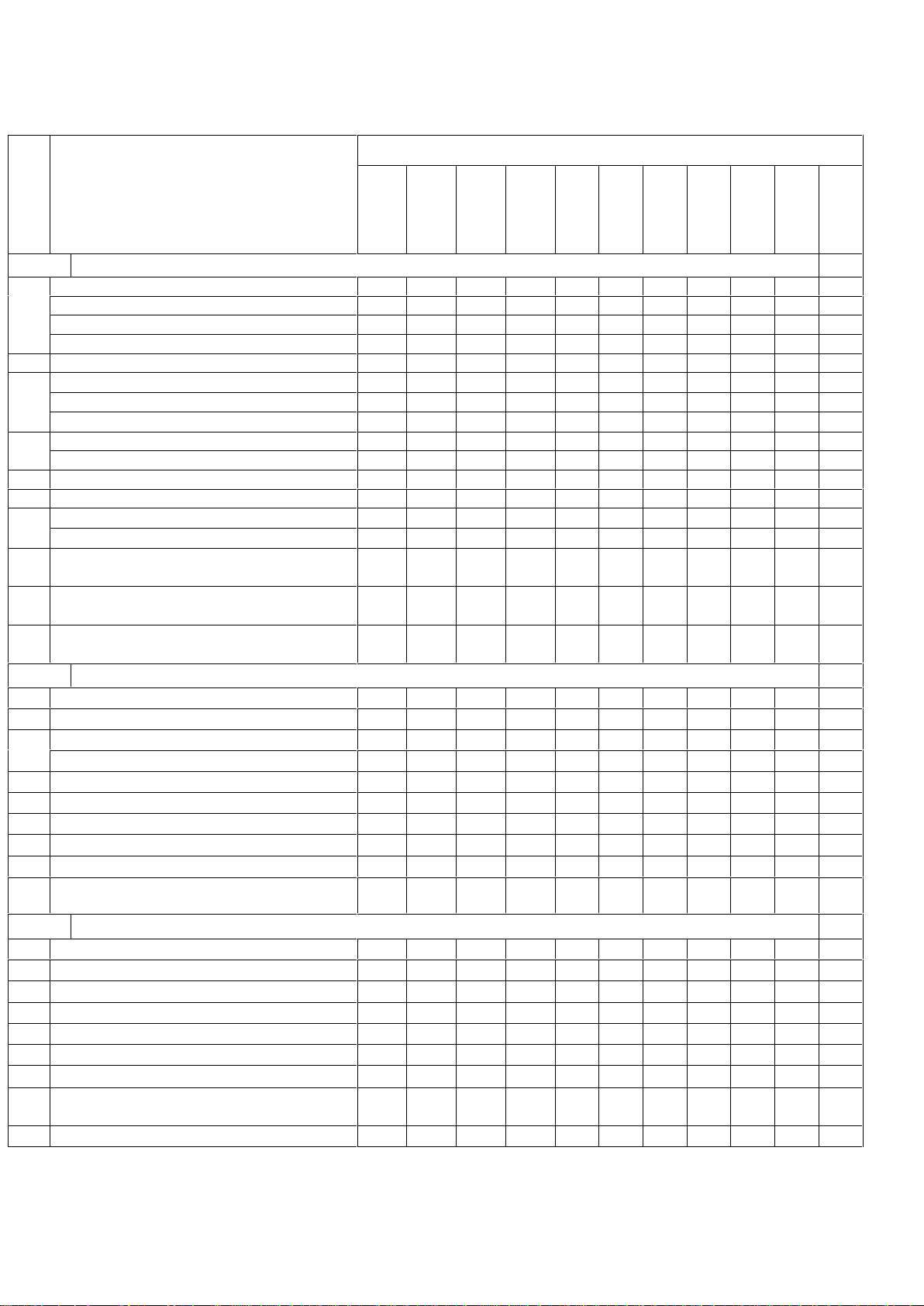
The material list for each set of support system is:
(*)
Required quantities for: flat roof / inclined roof (tiles)
(All the other quantities arethe same for flat roof or inclined roof installation)
Part
MODEL
125-1-150
125-1-200
150-1-200
150-1-230
150-2-150
200-1-200
200-1-230
200-1-260
200-2-200
300-2-200
300-2-230
SET OF SUPPORT FRAME PARTS
01
A1 profile in Π section 1465mm
(*)
---------
-/1
-/1
A125 profile in Π section 1107mm
(*)
2/1---2/1------
A150 profile in Π section 1377mm
(*)
-
2/1
2/1
2/1-2/1
2/1-2/1
2/1
2/1
A200 profile in Π section 1489mm
(*)
---
----2/1--
-
02
A12 profile in Π section 240mm
(*)
-/2
-/2
-/2
-/2
-/2
-/2
-/2
-/2
-/2
-/2
-/2
03
D125 profile in Π section 1671mm
2---2------
D150 profile in Π section 2091mm
-22
2-22-22
2
D200 profile in Π section 2266mm
---
----2--
-
04
H/H2:bracket in Π section 850mm
(*)
1/1
1/1
1/1
1/1
1/1
1/1
1/1
1/1
1/1--
H11/H12:bracket Π section1400mm(*
)
---
------1/1
1/1
05
I : angle bracket 173mm
22222222222
06
T : support bracket 160mm
44444444444
07
E1 :angle Z shape 2000mm
----2---22-
E2 :angle Z shape 2310mm
----------2
08
Stainless steel strips 833mm
(*)
(for inclined roof)
-/4
-/4
-/4
-/4
-/4
-/4
-/4
-/4
-/4
-/4
-/4
09
Insulated long pipe Ø15mm
(for close loop cold water)
1.56m
1.56m
2.07m
2.07m
1.85m
2.07m
2.07m
2.25m
2.25m
2.10m
2.22m
10
Insulated short pipe Ø 15mm
(for close loop hot water)
0.42m
0.42m
0.48m
0.38m
0.69m
0.50m
0.40m
0.40m
0,71m
0.40m
0.58m
SET OF FITTINGS
11
Compression Elbow Ø15 x 18x2.5 PE-X
11111111111
12
Compression Elbow Ø18 x 18x2.5 PE-X
11111111111
13
Compression Elbow Ø18 x Ø15
---
1
1-11111
Compression Union Ø18 x Ø15
111
-
-1-----
14
Tee connector female ½
˝ x Ø15 x Ø15
11111111111
15
End Cap male ½
˝
11111111111
16
Copper Ring ½
˝
11111111111
17
Compression End Cap Ø18
----2---222
18
Compression Connector Ø18 x Ø18
----2---222
19
Pressure Safety Valve 10 bar
(for open loop)
11111111111
SET OF BOLTS AND NUTS
20
Bolt Μ10x16 (DIN 933/8.8)
(*)
18/26
18/26
18/26
18/26
21
Nut Μ10 (DIN 934/8)
(*)
18/26
18/26
18/26
18/26
22
Bolt Μ6x20 (DIN 933/8.8)
44448444888
23
Washer Ø6 (DIN 9021)
44448444888
24
Anchored Bolt Μ8x60 (DIN 571)
44444444444
25
Washer Ø8 (DIN 9021)
44448444888
26
Plastic Rawlplugs D10
(*)
4/-
4/-
4/-
4/-
4/-
4/-
4/-
4/-
4/-
4/-
4/-
27
Cross Recess Counter Sunk Head Bolt
Μ8x20 (DIN 7969)
----4---444
28
Nut Μ8 (DIN 934/8)
----4---444
6
2.5. Thermo convention liquid
The thermal energy collected from the solar irradiation by the collector is transferred to the heat – exchanger
of the tank by the thermo convention liquid, which is naturally re circulated by the thermosiphonic principle in
the closed loop system. The heat exchanger is heating the domestic consumption water. The solution
contains inhibitors for antirust protection and propylenoglycol for antifreeze protection up to -15oC. If lower
temperature protection is needed please consult your supplier.
The solution is a non toxic, non-flammable chemical liquid; however normal protection measures should be
taken during handling. Keep it away from children.
Eyes protection: Protective glasses must be used.
Skin protection: PVC or rubber gloves must be used.
In case of contact with eyes, wash eyes with plenty of water for 15 minutes (with open eyelids)
In case of contact with skin simply wash with water and soap.
Physical Properties:
Phase: liquid
Color: Light red
Odor: nearly odorless
Specific gravity at 20oC : 1,03g/cm
3
Freezing point: -15oC
Boiling point: 106oC
Packing: Containers of 2ltr. & 4ltr. ready for usage.
2.6. Packaging, Transport and Storage
The solar collectors and the solar tanks are supplied individually packaged, the collectors in carton boxes
and the tanks with stretch film and expanding polystyrene. The collector model is indicated on the outside of
each box and the tank model is indicated outside of each package. Depending on the number of units
ordered, collectors can be supplied palletised in groups of up to 12 units. Collectors should always be during
transport and storage placed in horizontal position with the glass facing on top, otherwise there is danger of
water entering in the collectors from the ventilation holes at the back of the collector. They should not be
stored or transported in piles of more than 12 units. The tanks can be supplied palletised in groups of up to
10 units. Alternatively, under request, the whole system can be palletised in individual pallets. The tanks
should be always in vertical position during transportation and should not be stored or transported in piles of
more than 2 units. It is recommended to use special safety belts during transportation in order to avoid
movements and/or falling. The support system, the hydraulic accessories and the thermo-convention liquid
are delivered in one pallet, the exact content and models are indicated on the outside of each pallet.
2.7. Placement of the System
The choice of location, inclination and orientation of the solar system has to be determined at the design
stage of the installation. The installation of the solar system in the building should be carried out respecting
the instructions of the person in charge of the project, who should have taken into consideration the effect of
the orientation, inclination and possible shadows in the calculation of benefits of the solar system.
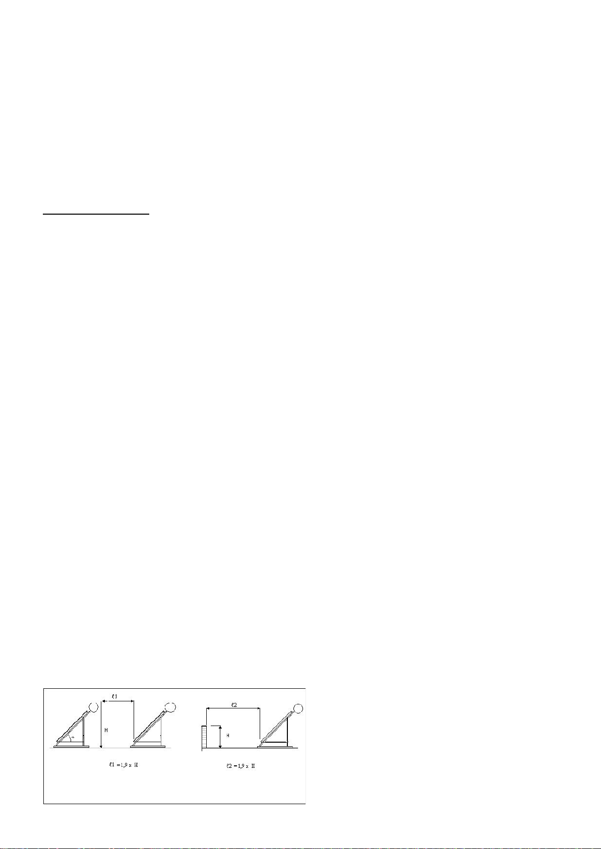
Particular attention should be paid to the minimum distance maintained between a wall or obstacle in front of
a system and it. During the calculation of this distance one should take into consideration the latitude of the
place, the inclination of the terrain and the period of use of the facility. Failure to have a more detailed
specification by the designer of the facility, the distance should not be less than the indicated below.

7
3. Warnings
Before starting installation, the installer should read and observe carefully the following warnings in order to
avoid danger of death, injury or property damages.
3.1. You may elevate on roof the parts of the solar system, ONLY when an internal staircase of enough
width, exists in the building reaching the roof. Otherwise you must use a proper CRANE to elevate the parts.
It is not allowed to stand at the edge of any roof (flat or inclined) and pull by ropes any part. DANGER OF
DEATH.
3.2 The collectors have a large surface exposed to wind. NEVER install a system with strong winds. Choose
a calm day. DANGER OF DEATH or heavy injury.
3.3. If the installation will be on an inclined roof (tiles), there is danger of slipping. Use always SAFETY
BELTS (securely fastened) from a higher position of roof. DANGER OF DEATH.
3.4. After completion of the installation make sure that all bolts and nuts are fastened well and the whole
system is securely fastened to the roof. The support system can withstand air velocities up to 97,2 km/hr.
Make sure that the fastening on roof can withstand as well at least same air velocity. DANGER OF DEATH.
3.5. Frequently some parts of the support systems have sharp edges. Use always gloves when you are
handling the support system, in order to avoid danger of injuring the hands. DANGER OF INJURY.
3.6. The collectors when exposed to solar irradiation during installation get very hot; above 120oC in 2-3
minutes. There is danger of burning the hands when touching the copper piping outlets. You must leave the
carton package cover ON the glass until completion of the installation, or you must use thermo resistance
gloves. DANGER OF INJURY.
3.7. If you are using hands to position the tank on the support system at least 2 people are needed for
systems 120-150.
It is preferred to use a crane. In this case make sure that the pulling belts are on each side between the
piping outlets of the boiler so that it cannot slip.
3.8. In cases where the solar system is large and the hot water consumption is low, the hot water in the solar
tank may reach temperatures up to 90oC. In this case there is danger of burns for the user, especially for
children.
It is strongly recommended to install a thermostatic mixing valve set at 55oC anywhere at the hot supply
piping and before the hot outlets of the building (before taps, showers, e.t.c.)
3.9. If the solar system is equipped with the (optional) electric immersion heater, the electrical connection
should be done by a fully licensed electrician following the national rules for electric installation.
The immersion heater is single phase 230 Volt of 2kW or 3 kW or 4 kW power.
There is an “earth point” on the flange of the heater which must be connected to the central “earth” of the
building. In any case the support of the solar system must be “earthed” with copper wire of 16 mm2to the
earthing grid of the building. This will also serve as lightning protection.
3.10 In a solar system equipped with the optional electric heater, after completion of electrical and plumbing
installation test the operation of the electric heater and thermostat, ONLY AFTER FILLING the tank with city
water. Otherwise the electric heater will be fused out. (destroyed)
3.11 Make sure that before filling the tank with city water the pressure safety non-return valve has been
installed on the cold water inlet with the arrow pointing to the tank. This valve will open and release the
pressure when by overheating or other reason it has exceeded 10 bar.
3.12. When handling the thermo-convention liquid make sure that you wear protective glasses for the eyes
and gloves for the skin.
3.13. When temporarily leave the collectors on the roof during installation ALWAYS position them with glass
facing the sky. Otherwise there is danger that water from rain may enter the collector from the back side
through the ventilation holes. If this happens the insulation will be wet and the glass will have humidity on
inside surface. Drying will take a very long time.
8
4. Recommendations
4.1 The cold water piping should withstand pressure of 1000 kPa. The hot water piping should withstand
temperature of 95oC at pressure 1000 kPa.
4.2. The cold and hot water piping should be well insulated to eliminate heat losses and prevent as possible
freezing. The insulation material should withstand weather conditions like rains, snow and solar irradiation.
4.3. The system should be protected always with antifreeze liquid as supplied by the company to prevent
from frost.
4.4. On the hot water supply piping, install a reliable thermostatic mixing valve set at 55oC to prevent higher
temperature hot water to reach the consumption points.
4.5. The system may only be installed in locations with lower values of sK(snow load) 0.64m and vm(average
wind velocity) 97.2km/h
4.6. The required solar irradiation for which overheating will happen is shown on the table below. The system
should not be used in climate zones with higher irradiation values than these.
SWH 200-2-S200
H (MJm-2)
Tsn (°C)
15.20
31.72
25.01
32.13
19.42
28.69
24.16
30.98
26.42
31.48
26.88
31.62
27.42
32.88
27.94
35.07
27.40
33.82
26.59
35.01
27.21
35.75
 Loading...