

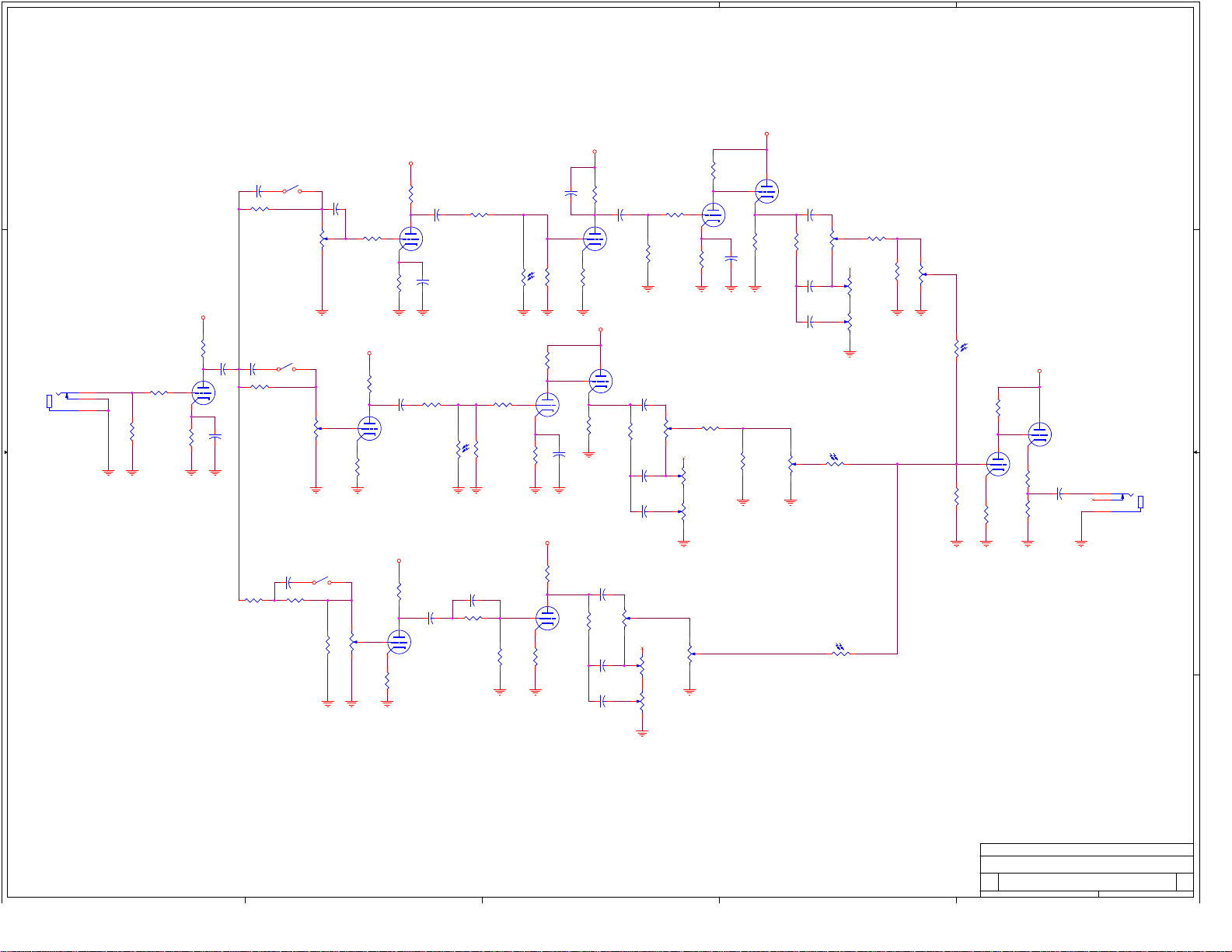
Soldano x88r schematic
5
4
3
2
1
D D
SW1
C3
BRIGHT LEAD
R5
470K
0.0022
VR1
500K
C4
0.001
R6
470K
R7
100K
1
U2-1
C6
0.022uF
R9
470K
2
12AX7
3
C5
R8
1uF
1.8K
OI1A
VTL5C1
34
A
B
C C
J1
IN
2
4
1
R2
68K
R1
1M
R3
C13
220K
C2
0.047uF
6
U1-2
7
12AX7
8
R4
C1
1.8K
1uF
470pF
R21
470K
SW2
BRIGHT CRUNCH
VR6
500K
A
R22
100K
C14
R24
0.022uF
1
U1-1
2
12AX7
3
R23
2.2K
680K
OI2A
VTL5C1
R26
U4-2
220K
7
12AX7
34
R25
330K
8
R28
1.8K
B
R11
C7
100K
0.001
6
U2-2
7
12AX7
8
R10
R12
1M
39K
C8
0.022uF
R13
330K
R14
220K
6
U5-2
7
12AX7
8
R16
1.8K
E
R27
100K
6
C15
0.1uF
1
U4-1
2
12AX7
3
R29
100K
C16
470pF
R30
47K
C17
0.022uF
C18
0.022uF
VR7
250K
R31
330K
VR8
1M
VR9
25K
R15
100K
E
1
U5-1
2
12AX7
3
C9
1uF
R17
100K
C10
470pF
R18
47K
C11
0.022uF
C12
0.022uF
VR2
250K
R19
330K
VR5
500K
R20
VR3
1M
VR4
25K
680K
34
OI3A
VTL5C1
D
R44
220K
6
U6-2
7
R43
470K
1
U6-1
2
12AX7
3
12AX7
8
R46
82K
C25
0.1uF
R47
2.2K
R45
2.2K
J2
OUT
2
4
1
R32
680K
VR10
500K
OI4A
3 4
VTL5C1
C
VR11
500K
C
R40
100K
R36
100K
6
U3-2
7
12AX7
8
R37
2.2K
C20
0.022uF
C21
120p
R38
2.2M
R39
330K
1
U3-1
2
12AX7
3
R41
2.2K
C22
470pF
R42
47K
C23
0.022uF
C24
0.022uF
VR12
250K
VR13
1M
VR14
25K
VR15
1M
OI5A
3 4
VTL5C1
SW3
R33
470K
C19
470pF
R34
470K
BRIGHT CLEAN
R35
39K
B B
A A
Title
SOLDANO X88R
Size Document Number Rev
1 1
C
5
4
3
2
Date: Sheet of
1
1 1Friday, July 12, 2002
5
D D
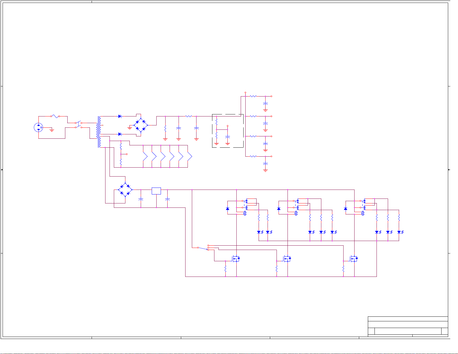
F1
1A SLO BLO
J1
AC PWR
C C
3
1 2
SW1
POWER
Hammond 269BX
T1
1
4
5
150VAC
6
150VAC
8
9
6.3VAC
D1, D2 1N5368B
D1
D2
10
D1 and D2 depend on how much voltage the transformer is
putting out and might not even be necessary The voltage
measurement on C1 should be less than its voltage rating by
around 18-20V. This measurement is taken without connecting
the B+ supplies to tubes, but with filaments wired and
connected.
D3-D6 can be replaced with similar 1000V fast recovery
rectifiers
To minimize inductive coupling wire filaments in this order. F1 is the filament of V1
- +
B B
All voltages for switching circuits are specified relative to their
floating ground. This floating ground should NOT be connected
to the signal ground.
Footswitch capabilities can easily be added to this schematic by
putting a SPST switch before SW2 so that it could be turned off when
footswitch is enabled and wiring the gates of Q1-Q3 to a footswitch
connector. Alternatively a 4 position rotary channel switch can be
used with one position left unwired.
4
D3-D6 MUR1100E
D3-D6
- +
R9
100
R10
100
Vref
D7-D10
1N4007
F6
SWITCH/INDICATION
POWER SUPPLY
C8
+
4700uF 16V
R1
150K 2W
F5
F4
U1
7805
+432V
F3
C9
+
4700uF 16V
R2
1K 2W
+
F2
C1
47uF 450V
+
C2
47uF 450V
F1
+5V
SW2
CHANNEL
3
Filament reference supply
R3
1M
Vref
R4
C3
+
100K
100uF/100V
D11
R11
47K
3
6
1
2
Q1
2N7000
2
D
R5
10K 2W
R6
10K 2W
R7
10K 2W
R8
10K 2W
D11-D13 1N4148
LS1
4
5
8
7
OI5A
TLP227
A
+
C4
22uF 450V
B
+
C5
22uF 450V
C
+
C6
22uF 450V
E
+
C7
22uF 450V
LS1-LS3 - HASCO HS212 or similar
R13
R12
43
390
D14
CLEAN
LS2
4
3
5
6
1
2
Q2
2N7000
8
7
OI4A
TLP227
R16
180
OI2A
VTL5C1
R17
43
D15
CRUNCH
R15
390
D12
R14
47K
LS3
4
3
5
6
1
2
Q3
2N7000
8
7
OI3A
TLP227
R19
390
D14-D16 are red LEDs w 4V voltage
drop and 25mA current rating
D13
R18
47K
R20
180
OI1A
VTL5C1
1
R21
43
D16
LEAD
A A
Title
X88R POWER SUPPLY, SWITCHING AND INDICATION
Size Document Number Rev
2 1
C
5
4
3
2
Date: Sheet of
1
1 1Tuesday, August 20, 2002
 Loading...