


S
S
o
ollsstt
a
arrtt--
1
1
P
P
MMiinniiaattuurree SSiinnggllee PPhhaassee SSoofftt SSttaarrtteerr
11--1188AA,, 223300VV
I
Innssttrruuccttiioonn
M
Maannuuaall
Ver. 13.01.2008

2 • Solcon Industries Ltd.
________________________________________________________________________________________________________
Solstart 1-P Manual
Index
1.
Safety & Warnings .................................................................................................................................. 3
1.1 Safety......................................................................................................................................................... 3
1.2 Attention .................................................................................................................................................... 3
1.3 Warnings.................................................................................................................................................... 3
2. General ..................................................................................................................................................... 4
2.1 Introduction................................................................................................................................................ 4
2.2 Soft-Start Characteristics...........................................................................................................................4
2.3 Rating and Frames size.............................................................................................................................. 4
2.4 Starter Selection......................................................................................................................................... 4
2.4.1 Motor current & Starting Conditions.............................................................................................4
2.4.2 Mains Voltage (line to line)...........................................................................................................4
2.4.3 By- Pass .........................................................................................................................................5
2.4.4 Starting Voltage adjustment...........................................................................................................5
2.4.5 Additional current limiting.............................................................................................................5
2.5 Signal reading with and without “SOLSTART-1P”.................................................................................. 5
2.6 Wiring Notes.............................................................................................................................................. 6
2.6.1 Short Circuit Protection .................................................................................................................6
3. Installation................................................................................................................................................ 6
3.1 Prior to Installation .................................................................................................................................... 6
3.2 Mounting.................................................................................................................................................... 6
3.3 Temperature range & heat dissipation.......................................................................................................6
4. Recommended Wiring Diagrams...........................................................................................................7
4.1 Typical connection..................................................................................................................................... 7
4.2 Connection with Starting booster............................................................................................................... 7
4.3 Wiring Connections...................................................................................................................................8
5. Back plate dimensions............................................................................................................................. 8
6. Setting and StartUp Procedure .............................................................................................................. 9
7. Technical Specifications........................................................................................................................ 10

Safety & Warnings• 3
1. SAFETY & WARNINGS
1.1 Safety
1
Read this manual carefully before operating the equipment and follow its
instructions.
2
Installation, operation and maintenance should be in strict accordance with this
manual, national codes and good practice.
3
Installation or operation not performed in strict accordance with these
instructions will void manufacturer’s warranty.
4
Disconnect all power inputs before servicing the soft-starter and/or the motor.
5
After installation, check and verify that no parts (bolts, washers, etc) have fallen
into the starter.
1.2 Attention
1
This product was designed for compliance with IEC 947-4-2 for class A
equipment.
2
Use of the product in domestic environments may cause radio interference, in
which case, the user may be required to employ additional mitigation methods.
3
Utilization category is AC-53a or AC53b, Form 1.
4
For further information, see Technical Specification.
1.3 Warnings
1
Internal components and P.C.Bs are at mains potential when the SOLSTART-1P
is connected to mains. This voltage is extremely dangerous and will cause death
or severe injury if contacted.
2
When SOLSTART-1P is connected to mains, even if control voltage is
disconnected and motor is stopped, full voltage may appear on starter’s output
and motor’s terminals. Therefore, for isolation purposes it is required to connect
an isolating device (C/B, switch, etc) upstream to the SOLSTART-1P.
3
The starter must be grounded to ensure correct operation, safety and to prevent
damage.
4
Check that Power Factor capacitors are not connected to the output side of the
soft starter.
5
Do not interchange line and load connections
The company reserves the right to make any improvements or modifications to its products without prior notice and does not
guaranty any data in its preliminary publishments .
________________________________________________________________________________________________________
3

4 • General
2. GENERAL
2.1 Introduction
The SOLSTART-1P is a Miniature Analogue soft starter which incorporates a thyristor to start a single phase squirrel cage
induction motor. By supplying a slowly increasing voltage, it provides soft start and smooth step-less acceleration, while drawing
the minimum current necessary to start the motor.
After the acceleration is completed a bypass is energized, supplying the motor its full voltage.
2.2 Soft-Start Characteristics
M%
Torque
I%U%
CurrentVoltage
100
100
400
10
50
100
2.3 Rating and Frames size
Max Motor
FLA
[A]
Starter type
FLC
[A]
Frame
Size
Dimensions
WxHxD
[mm]
Weight
[Kg]
18 Solstart-1P P1 130x50x40 0.2
2.4 Starter Selection
The starter should be selected in accordance with the following criteria:
2.4.1 Motor current & Starting Conditions
Select the starter according to motor's Full Load Ampere (FLA) - as indicated on its nameplate (even if the motor will
not be fully loaded).
The SOLSTART-1P is designed to operate under the following maximum conditions:
Ambient
Temperature
[
0
C]
Starting Current
[A]
Acceleration
Time
[sec]
40 400% x In 1.2
Max. Starts per Hour: twenty (20) starts per hour at maximum ratings.
For other starting conditions – consult factory
2.4.2 Mains Voltage (line to line)
220 – 240V (+10% - -15%)
Each starter is suitable for one of the above levels & for 50/60 Hz.
________________________________________________________________________________________________________

General. • 5
2.4.3 By- Pass
30A, 8310VA, 277VAC. (Maximum ratings)
The SOLSTART-1P incorporates a change-over internal by-pass. While starting, the by-pass allows current flow
through the thyristor. At the end of the starting process the by-pass closes and carries the current to the Motor.
The by-Pass is responsible for 2 functions at the end of acceleration:
1. The NO contact closes, shortens soft starter’s thyristor and bypasses it.
2. The NC contact opens and disconnecting the Starting booster (If exist – Consult factory for
utilizing a starter booster)
2.4.4 Starting Voltage adjustment
The SOLSTART-1P incorporates a potentiometer (P15) allows the user to adjust the starting voltage of the motor thus
controlling motor’s current and starting time.
2.4.5 Additional current limiting
In case of high starting current it is possible to add a starting buster to decrease the starting current.
Consult factory for additional information.
2.5 Signal reading with and without “SOLSTART-1P”
________________________________________________________________________________________________________
3
DOL starting without softstarter and current limiter
Soft-Starting with the
“SOLSTART-
1P”
soft-starter and the current limiter
Shown below are signal readings with and without the
“SOLSTART-1P”
CAUTION!
Power factor correction capacitors, if any, must not be installed on starter's Load side.
When required, Install capacitors on the Line side.
WARNING!
When Mains voltage is connected to the starter, full voltage will appear on the starter’s
load terminals. Therefore, for isolation purposes it is required to connect an isolating
device (C/B, switch, etc) upstream to the SOLSTART-1P (on the Line Side).

6 • Installation
2.6 Wiring Notes
2.6.1 Short Circuit Protection
The SOLSTART-1P should be protected against a short circuit by Thyristor Protection fuses.
The recommended fuses are: FWP-25B by Bussmann or equivalent.
3. INSTALLATION
WARNING!
Do not interchange line and load connections
3.1 Prior to Installation
Check that Motor’s Full Load Ampere (FLA) is lower than or equal to the starters Full Load Current (FLC).
3.2 Mounting
The starter must be mounted with all four mounting holes.
It is recommended to mount the starter directly on the rear metal plate of the equipment for better heat dissipation.
Do not mount the starter near heat sources.
Protect the starter from dust and corrosive atmospheres
Surrounding air temperature in the cabinet should not exceed 40ºC
3.3 Temperature range & heat dissipation
The starter is rated to operate over a temperature range of 0ºC (32ºF) to + 40ºC(104ºF).
Relative non-condensed humidity inside the enclosure should not exceed 93%.
ATTENTION!
Operating at surrounding air temp. (Inside the cabinet) higher than 40ºC may cause
damage to the starter.
Starter’s heat dissipation while motor is running and the internal bypass is closed is typically less than 0.1 x In (in
watts)
Example
: For an 18A motor, heat dissipation is less than 2 watts while running.
_______________________________________________________________________________________________________
9

Recommended Wiring Diagrams. • 7
4. RECOMMENDED WIRING DIAGRAMS
4.1 Typical connection
Solstart-1P
By-Pass Relay
AC single phase motor
(HVAC, Air Compressor,
Conveyor etc)
L
M
Rotation
Capacitor
N
M
C
NONC
COM
Gnd
LN
Gnd
L
N
MCap
Notes:
(1) Motor protection is not shown on this drawing
(2) Contact factory for different kind of motor than shown on this drawing.
4.2 Connection with Starting booster
Note:
(1) Consult factory to utilize this application
Solstart-1 P
By-Pass Relay
AC single phase motor
(HVA C , A ir C o mpres so r,
Conveyor etc)
L
M
Rota tio n
Capacitor
N
M
C
NONC
COM
Gnd
LN
Gnd
L
N
MCap
Starting
Booster
________________________________________________________________________________________________________
9
8 • Back plate dimensions
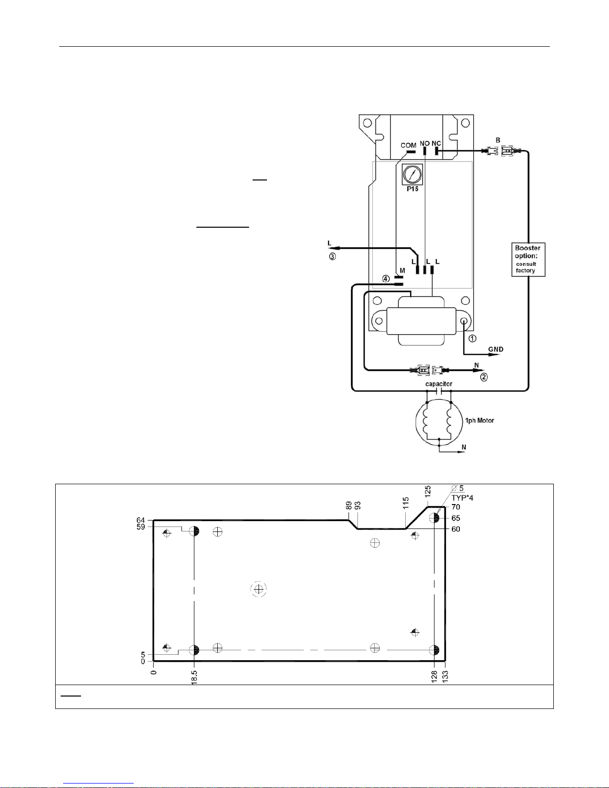
4.3 Wiring Connections
1 Connect grounding wire to the SOLSTART-1P.
2 Connect Neutral wire to the SOLSTART-1P as shown in
the drawing.
3 Connect phase to the PCB as shown in the drawing to
point “L” indicated on the PCB.
4 Make sure motor is connected to neutral. (not
via the
SOLSTART-1P)
5 Connect wire to the motor from point “M” indicated on
the PCB.
6 Leave wire B not connected and isolated
.
(Wire B is used for “Starting Booster” – Consult
factory.)
5. BACK PLATE DIMENSIONS
Note:
Add 20mm to width dimension (133+20mm) for transformer protrusion
_______________________________________________________________________________________________________
9

Setting and StartUp Procedure. • 9
6. SETTING AND STARTUP PROCEDURE
Start the motor and measure the
starting current by a recorder or
by
an oscilloscope
Starting current is
acceptable?
By-pass changes its
position after motor
ends starting?
Rotate potentiometer (P15) c.c.w
by 20º
Consult factory
Startup procedure ends.
Rotate potentiometer (P15) to its
maximum c. w
Note
:
By-Pass should change its position about one second after start process is completed and current should reduce to the
motor’s normal current.
________________________________________________________________________________________________________
9

10 • Technical Specifications
_______________________________________________________________________________________________________
9
7. TECHNICAL SPECIFICATIONS
Environment
Supply voltage One phase, line to line,
220 – 240 Vac +10% -15%
Frequency 50 / 60 Hz
Load Single Phase, Two-Wire, Squirrel
Cage Induction Motor
Degree of protection IP 00
Altitude Up to 1000 m above sea level Consult factory for derating
Adjustments
Ramp Up Time (soft start) 0.1 -1.2 sec.
Temperatures
Operating 0°C to 40°C
Storage -10°C to 70°C
Relative humidity 93 % - non condensed
 Loading...