


X1-AC
3.0kw - 5.0kw
User Manual
Solax Power Network Technology(Zhe jiang) Co,. Ltd.
614 .0034 6.02
Copyright Declaration
The copyright of this manual belongs to Solax Power Network Technology(Zhe jiang) Co,. Ltd.
Any corporation or individual should not plagiarize, par titially or fully copy ( including
software,etc.), and no reproduction or distribution of it in any form or by any means. All rights
reser ved. SolaX Power Network Technology (Zhe jiang) Co.,Ltd.. reserves the right of final
interpretation.

Contents
Contents
1 Note on this Manual
1.1 Scope of Validity
1.2 Target Group
1.3 Symbols Used
2 Safety
2.1 Important Safety Instructions
2.2 Explanation of Symbols
2.3 CE Directives
3 Introduction
3.1 Basic Features
3.2 Dimension
3.3 Terminals of Inverter
4 Technical Data
4.1 AC output/input
4.2 Internal Charger
4.3 Efficiency, Safety and Protection
4.4 General Data
5. Installation
5.1 Check for Transport Damage
5.2 Packing List
5.3 Mounting
03
03
03
03
04
04
08
09
10
10
13
14
13
13
14
14
15
16
16
16
17
6 Electrical Connection
6.1 Grid Connection
6.2 Battery Connection
6.3 Earth Connection
20
20
22
24
01

Notes on thi s ManualContents
6.4 Meter/CT Connection(optional)
6.5 485 Connection
6.6 DRM Connection
6.7 WiFi Connection(optional)
6.9 Inverter Manipulation
7 Firmware Upgrading
8 Setting
8.1 Control Panel
8.2 Menu Structure
8.3 LCD Operation
9 Troubleshooting
9.1 Trouble Shooting
9.2 Routine Maintenance
10 Decommissioning
Dismantling the Inverter10.1
Packaging10.2
Storage and Transportation10.3
25
28
28
29
30
32
34
34
35
36
54
54
58
59
59
59
59
1 Notes on this Manual
1.1 Scope of Validity
This manual is an integral part of X1-AC, It describes the assembly, installation,
commissioning, maintenance and failure of the product. Please read it carefully
before operating.
X1-AC-3.0X1-AC-3.6 X1-AC-5.0X1-AC-4.6
Note: “3.0” means 3.0kW.
Store this manual where it will be accessible at all times.
1.2 Target Group
This manual is for qualified electricians. The tasks described in this manual only
can be performed by qualified electricians.
1.3 Symbols Used
The following types of safety instructions and general information appear in this
document as described below:
Danger!
“Danger” indicates a hazardous situation which, if not avoided, will result in
death or serious injury.
Warning!
“Warning” indicates a hazardous situation which, if not avoided, could result
in death or serious injury.
Caution!
“Caution” indicates a hazardous situation which, if not avoided, could result
in minor or moderate injury.
02
Note!
“Note” provides tips that are valuable for the optimal operation of our
product.
03

2 Safety
SafetySafet y
2.1 Important Safety Instructions
Danger!
Danger to life due to high voltages in the inverter!
All work must be carried out by qualified electrician.
The appliance is not to be used by children or persons with
reduced physical sensory or mental capabilities, or lack of
experience and knowledge, unless they have been given
supervision or instruction.
Children should be supervised to ensure that they do not play
with the appliance.
Caution!
Danger of burn injuries due to hot enclosure parts!
During operation, the upper lid of the enclosure and the enclosure
body may become hot.
Only touch the lower enclosure lid during operation.
Caution!
Possible damage to health as a result of the effects of radiation!
Do not stay closer than 20 cm to inverter for any length of time.
Warning!
Authorized service personnel must disconnect AC power from
inverter before attempting any maintenance or cleaning or
working on any circuits connected to inverter.
Prior to the application, please read this section carefully to ensure correct and
safe application. Please keep the user manual properly.
Accesories only together with the inverter shipment are recommanded here.
Otherwise may result in a risk of fire, electric shock, or injury to person.
Make sure that existing wiring is in good condition and that wire is not
undersized.
Do not disassemble any parts of inverter which are not mentioned in installation
guide. It contains no user-serviceable parts. See Warranty for instructions on
obtaining service. Attempting to service the inverter yourself may result in a risk
of electric shock or fire and will void your warranty.
The installation place should be away from humid or corrosive substance.
Authorized service personnel must use insulated tools when installing or
working with this equipment.
Hazardous voltage will present for up to 5 minutes after disconnection from
power supply.
CAUTION-RISK of electric shock from energy stored in capacitor, Never operate
on the inverter couplers, the MAINS cables or when power is Battery cables
applied. After switching off the battery and Mains, always wait for 5minutes to let
the intermediate circuit capacitors discharge before unpluging battery inplug
and MAINS couplers.
When accessing the internal circuit of inverter, it is very important to wait 5
minutes before operating the power circuit or demounting the electrolyte
capacitors inside the device. Do not open the device before hand since the
capacitors require time to sufficiently discharge!
Measure the voltage between terminals + and - with a multi-meter UDCUDC
(impedance at least 1Mohm) to ensure that the device is discharged before
beginning work (35) inside the device.VDC
To protect the AC system,surge suppression devices (SPD type2) should be fitted
at the main incoming point of AC supply (at the custome’s cutout), located
between the inverter and the meter/distribution system; SPD (test impluse D1)
for signal line according to EN 61632-1.
04
WARNING !
Do not operate the inverter when the device is running.
WARNING !
Risk of electric shock!
05

SafetySafet y
Anti-Islanding Effect
►
• Islanding effect is a special phenomenon that grid-connected system still
supply power to the nearby grid when the voltage loss is happened in the
power system. It is dangerous for maintenance personnel and the public.
• X1-AC seires inverter provide Active Frequency Drift(AFD) to prevent
islanding effect.
►
PE Connection and Leakage Current
• The inverter incorporates a certified internal Residual Current Device (RCD)
in order to protect against possible electrocution and fire hazard in case of a
malfunction in the cables or inverter. There are two trip thresholds for the RCD
as required for certification (IEC 62109-2:2011). The default value for eletrocution
protection is 30mA, and for slow rising current is 300mA.
• If an external RCD is required by local regulations, check which type of RCD
is required for relevant eletric code. It recommends using a type-A RCD. The
recommended RCD values is 100mA or 300mA unless a lower value is required
by the specific local electric codes. When required by local regulations, the use of
an RCD type B is permitted.
WARNING !
High leakage current!
Earth connection essential before connecting supply.
For United Kingdom
• The installation that connects the equipment to the supply terminals shall
comply with the requirements of BS 7671.
• No protection settings can be altered.
• User shall ensure that equipment is so installed, designed and operated to
maintain at all times compliance with the requirements of ESQCR22(1)(a).
For Australia and New Zealand
• Electrical installation and maintenance shall be conducted by licensed
electrician and shall comply with Australia National Wiring Rules.
►
Battery Safety Instructions
SolaX X1-AC Series inverter should be worked with high voltage battery, for the
specific parameters such as battery type, nominal voltage and nominal
capacity etc., please refer to section 4.2.
As accumulator batteries may contain potential electric shock and short-circuit
current danger, to avoid accidents that might be thus resulted, the following
warnings should be observed during battery replacement:
•
1: Do not wear watches, rings or similar metallic items.
2: Use insulated tools.
3: Put on rubber shoes and gloves.
4: Do not place metallic tools and similar metallic parts on the batteries.
5: Switch off load connected to the batteries before dismantling battery
connection terminals.
6: Only personal with proper expertise can carry out the maintenance of
accumulator batteries.
• Incorrect grounding can cause physical injury, death or equipment malfunction
and increase electromagnetic.
• Make sure that grounding conductor is adequately sized as required by safety
regulations.
• Do not connect the ground terminals of the unit in series in case of a multiple
installation. This product can cause current with a d.c component, Where a residual
current operated protective (RCD) or monitoring (RCM) device is used for protection
in case of direct or indirect contact, only the RCD or RCM of type B is allowed
on the supply side of this product.
06
Note: The instruction applies to lithium battery and please refer to the lead-
acid battery Quick Installation Guide.
07

SafetySafety
2.2 Explanation of Symbols
This section gives an explanation of all the symbols shown on the inverter and
on the type label.
Symbols on the Inverter
SymbolExplanation
The inverter is working normally, when the blue light is on.
The battery communication is active, when the yellow light is on.
An error has occurred, when the red light is on.
Symbols on the Type Label
SymbolExplanation
CE mark.
The inverter complies with the requirements of the applicable
CE guildlines.
TUV certified.
RCM remark.
SAA certification.
Beware of hot surface.
The inverter can become hot during operation. Avoid contact
during operation.
Danger of high voltages.
Danger to life due to high voltages in the inverter!
Danger.
Risk of electric shock!
The inverter can not be disposed together with the household waste.
Disposal information can be found in the enclosed documentation.
Do not operate this inverter until it is isolated from battery and. main
Danger to life due to high voltage.
There is residual voltage existing in the inverter after powering off,
which needs 5 min to discharge.
• Wait 5 min before you reoperate the inverter.
2.3 CE Directives
This chapter follows the requirements of the European low voltage
directives, which contains the safety instructions and conditions of
acceptability for the endues system, which you must follow when installing,
operating and servicing the unit. If ignored, physical injury or death may
follow, or damage may occur to the unit. Read this instructions before you
work on the unit. If you are unable to understand the dangers, warnings,
cautions or instructions, please contact an authorized service dealer before
installing. Operating and servicing the unit.
The Grid connected inverter meets the requirement stipulated in Low Voltage
Directive (LVD) 2014/35/EU and Electromagnetic Compatibility (EMC) Directive
2014/30/EU. The unit is based on:
EN 62109-1:2010 ; EN 62109-2:2011 ; IEC 62109-1(ed.1) ; IEC62109-2(ed.1)
EN 61000-6-3:2007+A:2011 ; EN 61000-6-1:2007 ; EN 61000-6-2:2005
The grid connected inverter leave the factory completely connecting device and
ready for connection to the mains,the unit shall be installed in accordance with
national wiring regulations. Compliance with safety regulations depends upon
installing and configuring system correctly, including using the specified wires.
The system must be installed only by professional assemblers who are familiar
with requirements for safety and EMC. The assembler is responsible for ensuring
that the end system complies with all the relevant laws in the country where it is
to be used.
The individual subassembly of the system shall be interconnected by means of
the wiring methods outlined in national/international such as the national electric
code (NFPA) No.70 or VDE regulation 0107.
08
Observe enclosed documentation.
09

IntroductionIntroduction
3. Introduction
3.1 Basic features
X1-AC Seires is a high-quality inverter which can store energe into battery.
The inverter can be used to optimize self consumption, store in the battery for
future use or feedin to public grid. Work mode depends on the battery and user’s
preference.
·Advanced DSP control technology.
·Utilize the latest high-efficiency power component.
·Advanced anti-islanding solutions.
·IP65 protection level.
·Max. efficiency up to 97.0%.
·THD<2%.
·Safety & Reliability: transformerless design with software and hardware
protection.
·Export control.
·Power factor regulation.
·Friendly HMI.
- LED status indications.
- LCD display technical data, Human-machine interaction through press
key.
- Dry contact communication interface.
- Remote control via modbus RTU
- Upgrade through USB interface.
- Pocket Wi-Fi monitoring.
- Control loads’ switch intelligently by RF.
- Energy conservation.
3.2 Dimension
341 .5mm
X1-ACX1-AC
143 .0 mm
430 .0 mm
10
11

IntroductionTechnical Data
3.3 Terminals of inverter
Object
A
B
C
D
E
F
G
H
I
Description
Battery connection area
Port for external Pocket WiFi/GPRS/LAN
External meter or CT port
AC connector
DRM port
Groud screw
RS485
Battery communication
USB port for upgrading
ABCD
+
BAT
DRM
-
FEHIGEE
Meter
485
WiFi/LAN/GPRS
A
4. Technical Data
4.1 AC output/input
Model
AC
BMS
Upgrade
AC output
Norminal AC power[VA]
Max. apparent AC power[VA]
Rated grid voltage(range)[V ]
Rated grid frequency[Hz]
Norminal AC current[A]
Max.AC current[A]
Max. overcurrent protection[A]
Displacement power factor
Total harmonic distortion(THDi)
Load control
AC input
Norminal AC power[VA]
Max. apparent AC power[VA]
Rated grid voltage(range)[V ]
Rated grid frequency[Hz]
Norminal AC current[A]
Max.AC current[A]
Max. short current(Isc)[A]
Displacement power factor
X1-AC-3.0
3000
3000
13
13.6
3000
3000
13
13.6
X1-AC-3.6
3680
3680
220/230/240 (180 to 280)
16
16.8 (16 for G98)
0.8 leading...0.8 lagging
3680
3680
220/230/240 (180 to 280)
16
16.8 (16 for G98)
0.8 leading...0.8 lagging
X1-AC-4.6X1-AC-5.0
4600
4600
50/60
20
21
45
< 2%
optional
4600
4600
50/60
20
21
45
4999
4999
230/240 (180 to 280)
21.7
21.7
4999
4999
21.7
21.7
12
WARNING !
Qualified electrician will be required for the installation.
13

Technical Data
Technical Data
4.2 Internal Charger
Model
Battery type
Battery voltage range[V ]
Recommended battery voltage[V ]
Rated charge/discharge current[A]
Max. charge/discharge current[A]
Communication interfaces
Reverse connect protection
X1-AC-3.0
4.3 Efficiency, Safety and Protection
Model
Max. efficiency
Max . Batte ry charge e ffici ency
(AC to BAT )(@full l oad)
Max. Battery discharge efficiency
(BAT to AC)(@full load)
Safety & Protection
Over/under voltage protection
DC isolation protection
Grid protection
DC injection monitoring
Residual current detection
Anti-islanding protection
Over load protection
Over heat protection
X1-AC-3.0
97.0%97.0%97.0%97.0%
97.0%97.0%97.0%97.0%
97.5%97.5%97.5%97.5%
X1-AC-3.6X1-AC-4.6X1-AC-5.0
Lithium/Lead-acid battery
70-400
300VDC
25A
35A
CAN
Yes
YES
YES
YES
YES
YES
YES
YES
YES
X1-AC-4.6
X1-AC-5.0
X1-AC-3.6
4.4 General Data
Model
Dimension [W/H/D](mm)
Dimension of packing [W/H/D](mm)
Net weight [kg]
Gross weight [kg]
Installation
Operating temperature range[℃]
Storage temperature [℃]
Storage/Operation relative humidity
Altitude [m]
Ingress Protection
Protective Class
Over Voltage Category
Pollution Degree
Cooling
Inverter Topology
Communication interface
X1-AC-3.0
15.515.516.316.3
18.518.519.319.3
X1-AC-3.6X1-AC-4.6X1-AC-5.0
430*341.5*143
554*446*259
Wall-mounted
-25~+60 (derating at 45)
-25~+60
0~100%, condensing
≤2000
IP65(for outdoor use)
Ⅰ
Ⅲ(MAINS),Ⅱ(DC)
Ⅲ
Natural
Non-isolated
RS485, Meter/CT(optional), Wifi(optional), RF(optional), DRM, CAN, USB
14
15

InstallationInstallation
5. Installation
5.1 Check for Physical Damage
Make sure the inverter is intact during transportation. If there is any visible
damage, such as cracks, please contact your dealer immediately.
5.2 Packing List
Open the package and take out the product, please check the accessories first.
The packing list shown as below.
X1-ACX1-AC
X1-AC
I
Object
A
B
C
D
E
F
A
E
J
Description
Inverter
Bracket
Expansion tubes & Expansion screws
AC connector
Battery connectors (1*positive, 1*negative)
Waterproof connector with RJ45 (4*RJ45)
BCD
F
X1-AC 3.0KW-5.0KW
G
KLM
Object
G
H
I
J
K
L
M
N
Description
Ring terminal(for external enclosure grounding)
Set screw( for mounting)
User manual
Warranty card
Quick installation guide
Meter(optional)
Current Sensor(or called CT) (optional)
Wifi/GPRS/LAN module (optional)
5.3 Mounting
Installation Precaution
X1-AC Series inverter is designed for outdoor installation (IP 65).
Make sure the installation site meets the following conditions:
H
N
Not in direct sunlight.
Not in areas where highly flammable materials are stored.
Not in potential explosive areas.
Not in the cool air directly.
Not near the television antenna or antenna cable.
Not higher than altitude of about 2000m above sea level.
Not in environment of precipitation or humidity (>95%).
Under good ventilation condition.
The ambient temperature in the range of -20℃ to +60℃.
The slope of the wall should be within ±5°.
The wall hanging the inverter should meet conditions below:
1.Solid brick/concrete, or strength equivalent mounting surface;
2.Inverter must be supported or strengthened if the wall’s strength isn’t
enough(such as wooden wall, the wall covered by thick layer of decoration)
Please AVOIDE direct sunlight, rain exposure, snow laying up during installation
and operation.
16
17

Installation Installation
Space Requirement
Ø
Step 2 Match the inverter with wall bracket
300mm
Table Available Space Size
PositionMin.size
300mm300mm
300mm
Mounting Steps
Ø
Tools required for installation.
Installation tools : crimping pliers for binding post and RJ 45, screwdriver,
manual wrench and 6
Left
Right
Top
Bottom
Front
300mm
300mm
300mm
300mm
300mm
d) Hang the inverter over the bracket, move the inverter close to it,
slightly lay down the inverter, and make sure the 3 mounting bars on the
back are fixed well with the 3 grooves on the bracket.
*Please refer to the Quick Installation Guide for details.
a)b)
Step 1 Hang the inverter over the bracket, move the inverter close to it,
a) Use the wall bracket as a template to mark the position of the 3
holes on the wall.
b) Drill holes with driller, make sure the holes are deep enough (at
least 50mm) for installation, and then tighten the expansion tubes.
c) Install the expansion tubes in the holes, and tighten them. Then
install the wall bracket by using the expansion screws.(Φ10 driller,
torque: 2.5±0.2Nm)
18
c)d)
19

Ele ctrical Connec tionEle ctrical Connec tion
6. Electrical Connection
6.1 Grid Connection
X1-AC series inverter are designed for single phase grid. Voltage is 220/230/240V,
frequency is 50/60Hz. Other technical requests should comply with the
requirement of the local public grid.
Table 4 Cable and Micro-breaker recommended
Model
Model
Copper Cable
Micro-breaker
X1-AC-3.0
X1-AC-3.0
4-5mm²
20A20A32A32A
X1-AC-3.6X1-AC-4.6X1-AC-5.0
X1-AC-3.6
4-5mm²5-6mm²5-6mm²
Micro-breaker should be installed between inverter and grid, any load should
not be connected with inverter directly.
Connection Steps
a) Check the grid voltage and compare with the permissive voltage range (refer
to technical data).
b) Disconnect the circuit-breaker from all the phases and secure against re-
connection.
c) Trip the wires:
- Trip all the wires to 52.5mm and the PE wire to 55mm.
- Use the crimping plier to trip 6mm of insulation from the end of wire.
X1-AC-4.6X1-AC-5.0
d) Separate the AC plug into three parts as below.
- Hold the middle part of the female insert, rotate the back shell to
loose it, and datach it from female inset.
- Remove the cable nut (with rubber insert) from the back shell.
e) Slide the cable nut and then back shell onto the cable.
f) Insert the tripped end of each three wires into the appropriate hole in
the female insert, and then tighten each screw (to tighten each wire in
place). ( PH1 cross screwdriver, torque:0.8±0.1Nm)
g) Screw down the threaded sleeve the pressure screw.
h) Screw down the pressure screw.(torque:3.0±0.3Nm)
20
I) Connect the AC plug to the inverter.
6mm
21

Ele ctrical Connec tionEle ctrical Connec tion
6.2 Battery Connection
Charging & discharging system of X1-AC series inverter is designed for
high-voltage lithium batterry or lead-acid battery.
Before choosing battery, please note the maximum voltage of battery can not
exceed 360V, and the battery communication should be compatible with X1-AC
inverter.
Battery breakerØ
Before connecting to battey, please install a nonpolarized DC breaker to make sure
inverter can be securely disconnected during maintanance.
Model
Model
Model
Voltage
Current[A]
Battery connection diagramØ
X1-AC-3.6X1-AC-4.6X1-AC-5.0
X1-AC-3.0
X1-AC-3.0
X1-Hybrid-3.0-NX1-Hybrid-3.7-NX1-Hybrid-4.6-NX1-Hybrid-5.0-N
X1-AC-3.6
Nominal voltage of DC breaker should be larger than maximum
voltage of battery.
+
BAT
-
Meter
DRM
485
WiFi/LAN/GPRS
X1-AC-4.6X1-AC-5.0
50A
AC
BMS
Upgrade
Note!
The battery communication can only work when the battery BMS is
compatible with the inverter.
Power Connection Steps:
Ø
Step1. Choose the 10 AWG wire and strip the cable to 15mm.
Step2. Insert the stripped cable up to the stop ( negative cable for DC plug(-) and
positive cable for DC socket(+) are live). Hold the housing on the screw
connection.
Step3. Press down spring until it clicks audibly into place.(it must be possible to
see the fine wire strands in the chamber)
Step4. Tighten the screw connection(tighten torque:2.0±0.2Nm)
Step5. Plug the conntector into the corresponding BAT connector on inverter.
Step2.
screw connection
DC plug housing(-)
Step3.Step 4.
spring
screw connection
DC socket housing(+)
Nonpolarized
Power connection
DC breaker
-
+
CAN
high-voltage lithium battery.
Communication connection
Note: When working with Pylontech batteries, It is recommended the number of battery module
(H48050-15S) is 2-6 and the number of battery manager system (SC0500A-100S) is 1.
BMS PIN DefinitionØ
Communication interface bewteen inverter and battery is CAN with a RJ45
connector.
1
8
BMS
1
NTC
34678
2
GND GND
BMS_CANH
5
BMS_CANL
GND
22
chamber
wire strands
Step5.
+
BAT
DRM
-
WiFi/LAN/GPRS
BMS_485BBMS_485A
Not e: The pos itive l ine and n egati ve line ar e not all owed to a ccess anti-Li ne.
AC
Meter
485
BMS
Upgrade
23
Ele ctrical Connec tionEle ctrical Connec tion
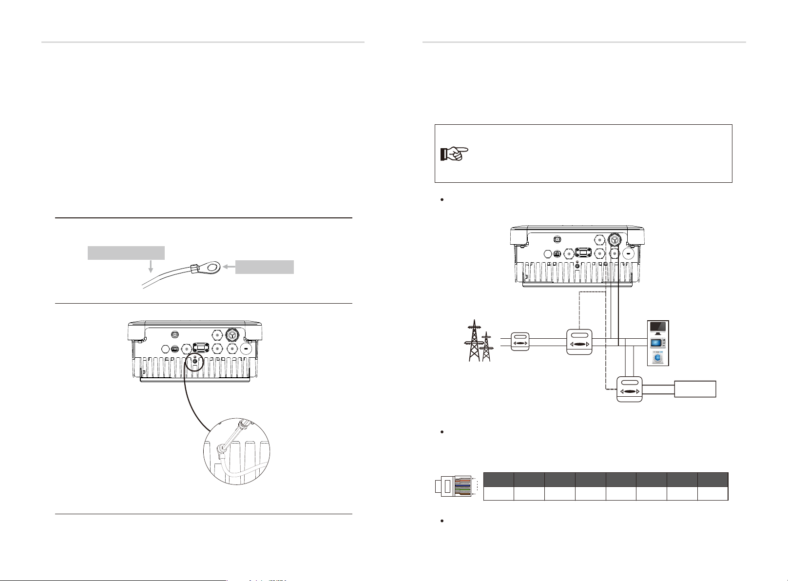
6.3 Earth Connection (mandatory)
Users must addtionally earth the inverter to the enclosure of a second earthing or
equipotential bonding. This prevents electric shock if the original protective
conductor fails.
Earth Connection Steps:
Ø
Step1. Strip the earthing cable insulation and insert the stripped cable into the
ring terminal, then clamp it .
Step2. Place the ring terminal into the earthing rod and screw the earthing screw
tightly.( Φ4 hexagon wrench, torque:1.5±0.2Nm)
Step1
Cable size: 10AWG.
ring terminal
Step2
+
BAT
-
Meter
DRM
485
WiFi/LAN/GPRS
AC
BMS
Upgrade
6.4 Meter/CT Connection
Meter connectionØ
Meterisusedformonitoringthepowerusageforentirehouse,atthemeantime,
inverterwillalsoneedthedatafromMetertoachievetheExportControlFunction.
Note!
It is necessary to connect meter to inverter otherwise inverter will
shutdown with a “Meter fault” alert.
The meter communication only works when meter is compatible
with the inverter.
Meter connection diagram
Electrical
grid
Home Electric meter,
+
BAT
-
Single phase
DRM
meter
Meter1
WiFi/LAN/GPRS
Meter
485
AC
BMS
Upgrade
Load
L
N
other generator
24
Meter2
Meter PIN Definition
Communication interface bewteen inverter and meter is BMS port with a RJ45
connector.
1
12345678
XXX
8
X
X
GND
485A485B
Meter Connection Steps:
Please refer to Page 27.
25

Ele ctrical Connec tionEle ctrical Connec tion
Meter
CT Connection Steps:
Ø
The current sensor measures the current on the phase wire that runs between the
inverter and the grid. This enables the inverter to determine the Power
requirements of the connected consumer. The current sensor is connected to the
CT port on the inverter.
NOTE!
• Do not place the sensor on the N Wire or the earth wire.
• Do not place the sensor on the N and L wire simultaneously.
• Do not place the sensor on the L wire going to the consumer.
• Do not place the sensor with the arrow pointing to the
generation meter.
• Do not place the sensor on the non-insulated wires.
• Do not use the wire over 25m.
NOTE!
• The sensor can be upgraded to meter.
• With a one phase meter provided by SolaX can monitoring
the 24hr usage of electric.
• With a three phase meter provided by SolaX can implement
three phase compensation.
CT connection diagram
Electrical
grid
+
BAT
-
Meter
DRM
485
WiFi/LAN/GPRS
AC
BMS
Upgrade
Load
L
CT PIN Definition
When connectingthe RJ45 connector with the wire of the CT, please follow the
below sequence :
1
12345678
CT+XX
8
CT-
X
X
XX
CT Connection Steps:
1. Insert the CT terminal on the current sensor into the Meter port on the
inverter.
+
BAT
DRM
-
WiFi/LAN/GPRS
AC
Meter
485
BMS
Upgrade
→
Public grid
AC port
L line
2. Place the current sensor around the phase wire L which the inverter is
connected.
3. Place the current sensor around the phase wire L to measure the current
going to or coming from the grid.
4. Make sure the current sensor is installed in the right direction: The arrow
on the current sensor must point to the public grid.
Home Electric meter,
Pub lic
Gri d
N
L line
CT
26
Meter
27

Ele ctrical Connec tionEle ctrical Connec tion
WiFi/LAN/GPRS
485
DRM
Meter
6.5 485 Connection
485 is provided the function of remote control that allows external control device
to make the inverters remote cluster control through 485 port on thr inverter.
485 PIN Definition:
Ø
1
12345678
COM0
8
485 Connection Steps:
Ø
Shut DownGND
485A
485BXXX
Please refer to the bellow(Page 28).
6.6 DRM Connection
DRM is provided to support several demand response modes by emitting control
signals as below through DRM port on the inverter.
Note: Only PIN6(DRM0) is available now, and other PIN functions are being developed.
DRM PIN Definition:
Ø
1
12345678
DRM1/5
8
Communication Connection Steps Of Meter, RS485 and DRM:
Ø
DRM2/6DRM3/7
DRM4/8
+3.3VDRM0GNDGND
6.7 WiFi Connection(optional)
Inverter provides a WiFi port which can collect data from inverter and
transmit it to monitoring-website via a Pocket WiFi.
(Purchase the product from supplier if needed)
Diagram
Ø
X1-ACX1-AC
Router
WiFi Connection Steps:
Ø
Step1. Plug Pocket Wifi/GPRS/LAN into “WiFi/LAN/GPRS” port at the bottom of
the inverter.
Step2. Build the connection between the inverter and router.
Step3. Create a user account on the SolaX web.( Please check the Pocket WiFi user
manual for more details)(torque:0.6±0.1Nm)
Could
Please kindly noted the PIN definition and port position will be slightly different.
1. Prepare RJ45 connector and a communication cable.
2. Trip the insulation from the communication cable.
3. Let the communication cable pass though the waterproof connector with
RJ45, then insert it into the RJ45 connector following the PIN definition rule.
Han d tight en,to rgue:1 .5±0. 1NmHan d tight en,to rgue:1 .2±0. 1Nm
4. Crimp the RJ45 connector with the crimping plier.
5. Insert the cable into the corresponding port of the inverter, and tighten the
waterproof connector.
28
29

Ele ctrical Connec tionEle ctrical Connec tion
6.8 Inverter Manipulation
Start inverter after checking all below steps:
Ø
Ensure the inverter fixed well on the wall.
Make sure all the AC wirings are completed.
Make sure the meter is connected well.
Make sure the battery is connected well.
Turn on the AC and battery switch.
Press the “Enter” key for five seconds to exit Off Mode.(The mode is factory
defaulted as Off Mode)
Inverter
-
+
SolaX meter
Main switch
5
Check the inverter:
Ø
Step1. Check the status of indicators and LCD screen. The left indicator should
be blue and the indicator screen should display the main interface.
Note!
If the left indicator is not blue please check below the two points:
- All the connections are correct.
- All the external breakers are switched on.
Step2. There is a setting guide on the LCD screen if it is the first time to start up,
please follow it. For specific setting, please refer to section 8 (Setting).
Step3. Set WiFi according to wifi user manual.
Step4. Operate “Self Test”. (applies to Italy only)
Self-test in accordance with CEI 0-21(applies to Italy only)
Ø
The self-test is only required for inverters, which are commissioned in Italy. The
Italian standard requires that all inverters feeding into the utility grid are equipped
with a self-test function in accordance with CEI 0-21. During the self-test, the
inverter will consecutively check the protection reaction times and values for
overvoltage, undervoltage, overfrequency and underfrequency.
PE
RCD
E-BAR
Note: External connections should be made according to the local regulations.
30
Battery
Selftest function is available at any time, and the test report will show on the LCD
display for end-user.
Shut down the inverter :
Ø
All you have to do is turn off the AC switch and battery switch.
31

Firmware Up grading
Firmware Up grading
7. Firmware Upgrading
User can upgrade inverter’s firmware via a U-disk.
Preparation
Ø
Please ensure the inverter is steadily powered on.
Inverter must keep the battery on through whole procedure of upgrading.
Please prepare a PC and a U-disk.
Warning!
Ø
Step1. Please contact our service support to get the update les, and extract it
into your U-disk as follow:
“update\ARM\618.00211.00_X1AC_Manager_Vx.xx_xx-xx.usb”;
“update\DSP\618.00209.00_X1AC_Master_Vx.xx_xx-xx.hex”;
Note: Vx.xx is version number, xx-xx is the le completion date.
Step2. Press the “Enter” key for 5 seconds to enter Off Mode. Then unscrew the
waterproof lid and insert U-disk into the “upgrade” port at the bottom of the inverter.
Make sure the inverter charged normally (the battery capacity is stable),
otherwise it may result in serious failing during upgrading.
Upgrading Steps:
Warning!
Make sure the directory is in accordance with above form strictly!
Do not modify the program file name, or it may cause the inverter
not work anymore!
Step2
Step3
U-disk
Update
>ARM
DSP
Warning!
If the upgrading is broken off during operation, please ensure the inverter
is steadily powered on and reinsert the U-disk.
Update(ARM)
Upd ating----- ----2 5%
Step3. The LCD will be shown as the picture bellow. Then press up and down to
select the one that you want and press “OK” to confirm to upgrade.
Step4. After the upgrade is finished, the LCD will display “succeed”(only for DSP
upgrades), please remember to pull off the U-disk, screw the waterproof lid and press
the “Esc” to return to the Main interface. Then press the “Enter” key to exit Off Mode.
32
33
SettingSetting
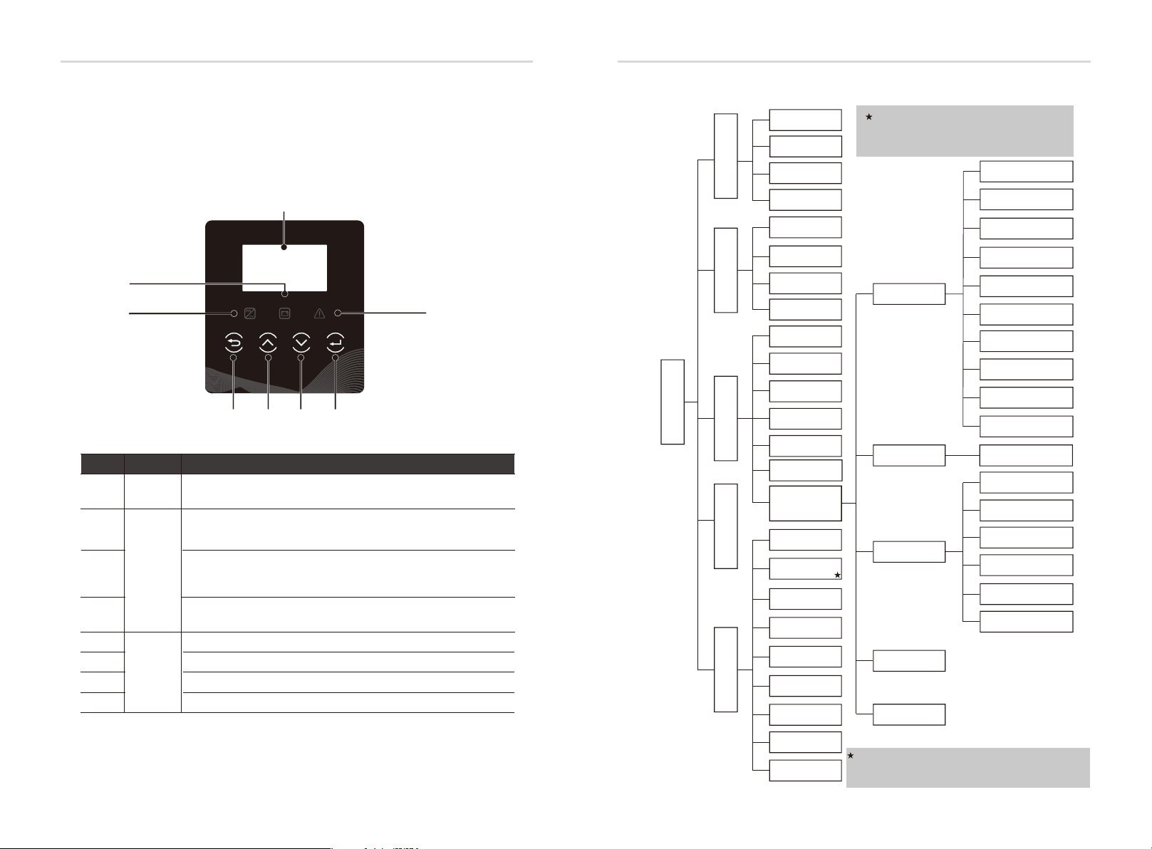
8. Setting
8.1 Control Panel
C
B
Object
A
B
C
D
E
F
G
H
Name
LCD
Screen
Indicator
LED
Function
Button
A
D
X1-ACX1-AC
EFGH
Description
Display the information of the inverter.
Light in blue: The inverter is in normal status.
Flash in blue: The inverter is in waiting status.
Light in yellow: The battery communication is normal.
Flash in yellow: The battery is in idle mode.
Light in red: The inverter is in fault status.
ESC button: Return from current interface or function.
Up button: Move cursor to upside or increase value.
Down button: Move cursor to downside or decrease value.
OK button: Confirm the selection.
8.2 Menu Structure
Status
History
Menu
Setting
System Switch
About
Grid
Charger
Load
Charger-setting
Inverter Yield
Load Consume
Meter Yield
Error Logs
Date Time
Language
Work Mode
RF Control
RS485/Modbus
Self Test
Advanced
need password
Inverter SN
Register SN
Inverter Type
Inverter DSP1
Inverter DSP2
Manager ARM
Internal Code
All advance setting can only be set
by the technician or the installer with
the installer password.
Safety
Power Factor
Grid
Export Control
On-grid
Battery
Reset
Meter Setting
New Password
Remote Control
Grid Service
P(U) Function
DRM Function
W(Gra)
Power Limit
Charger
Reset Errorlog
Reset Meter Energy
Reset Load Consume
Config Guide
Reset Inverter Energy
Factory Reset
34
SystemRunTime
BAT_Version
Register SN: it indicates the serial number of the
external monitoring devices,such as pocket WiFi,
pocket LAN and pocket GPRS.
35

SettingSetting
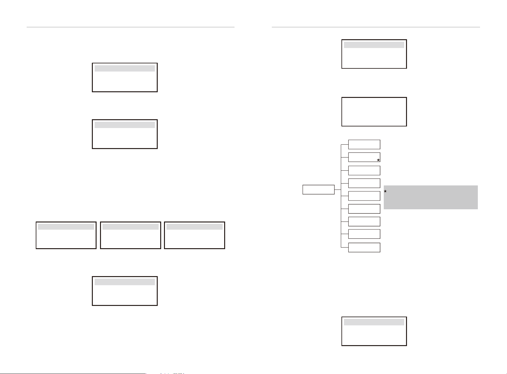
Status
8.3 LCD Operation
Ø
LCD Digital Display
The main interface is the default interface, the inverter will automatically jump to
this interface when the system started up successfully or not operated for a
period of time.
The information of the interface is as below. “Power” means the instant output
power; “Today” means the power generated within the day. “Battery” means the
left capacity of lithium battery energy(%) shown as the table, while the unit of
lead-acid battery is voltage(V).
Power 0W
Today 0.0KWh
Battery
Normal
%
Menu interface
The menu interface is a transfer interface for user to get into another interface
to change the setting or getting the information.
-User can get into this interface by pressing “OK” button when LCD displays the
main interface.
-User can select interface by moving the cursor with function button,and press
“OK” to confirm.
Menu
Status
History
Settings
Grid
Charger
Status
Load
Charger-settings
● Status
The status function contains three items of the inverter(grid, charger and Load).
Press up and down to select and press “OK” to confirm the selection, press “ESC”
to return to Menu.
Status
Grid
Charger
Load
a) Grid
This status shows the current grid condition such as voltage, current, output
power , the local consumed power and the frequency.
Pout measures the output of the inverter;
Pgrid measures power export to or import from grid.
Positive value means the energy feeds into grid, negative value means the
energy used from the grid.
36
Status
History
Menu
Setting
System Switch
Grid
U 000.0V
I 00.0A
Pout 00.0W
About
37

SettingSetting
b) Charger
This status shows the charger situation of the system, including the battery
voltage, charge or discharge current and power, battery capacity, battery
temperature( “+” means in charging; “-” means in discharging) and system
voltage.
Charger
U 100.0V
I +1.0A
P +100W
c) Load
If the inverter is plugged with a smart plug, this status shows the real time
load power, include load1 power, load1 switch, load2 power and load2
switch.
L1 Power
Load
0.0W
c) Charger-Settings
The user can watch the parameters (min capacity, max charge current and
max discharge current) of the lead-acid battery, if the user choose the lead-
acid battery.
History
Ø
History
● History
Inverter Yield
Load Consume
Meter Yield
Error Logs
The history function contains four items of the information: Inverter yield, load
consume, meter yield and error logs.
Press up and down to select, and press “OK” to confirm the selection, press “ESC”
to return to Menu.
History
Inverter Yield
Load Consume
Meter Yield
a) Inverter Yield
This Inverter Yield contains four items: OutputGridToday, OutputGridTotal,
InputGridToday and InputGridTotal.
38
ChargerSettings
>Min Capacity
20%
ChargerSettings
Imax_charge
35A
Chargersettings
Imax_discharge
35A
Inverter Yield
>OutputGridToday
0.8KWh
39

SettingSetting
b) Load consume
The Load consume contains the energy consumed by specific loads by today
and total.
Load consume
>Load 1 consume
Load 2 consume
c) Meter Yield
The Meter Yield contains four items: FeedInToday, FeedInTotal, ConsumeToday
and ConsumeTotal.
d) Error Logs
The Error logs record the lastest six error messages happened.
Meter Yield
>FeedInToday:
0.0KWh
Error logs
>
No error
Ø
Setting
Setting
(a)
Date Time
(b)
Language
c)(
Work Mode
(d)
Relay Control
(e)
RS485/Modbus
(f )
Self Test
(g)
Advanced
need password
(g- 1)
On-grid
(g- 2)
Battery
(g- 3)
Reset
(g- 4)
Meter Setting
Safety
Power Factor
Grid
Export Control
Remote Control
Grid Service
P(U) Function
DRM Function
W(Gra)
Power Limit
Charger
Reset Errorlog
Reset Meter Energy
Reset Load Consume
Config Guide
Reset Inveter Energy
Factory Reset
(g- 1-1)
(g- 1-2)
(g- 1-3)
(g- 1-4)
(g- 1-5)
(g- 1-6)
(g- 1-7)
(g- 1-8)
(g- 1-9)
(g- 1-10)
(g- 2-1)
(g- 3-1)
(g- 3-2)
(g- 3-3)
(g- 3-4)
(g- 3-5)
(g- 3-6)
40
(g- 5)
New Password
● Setting
This function is used for setting the time, connection, battery, grid and
others below of the inverter.
Enduser can set Date Time, Language, Woke Mode, Relay Control and
RS485CommAddr directly.
But for advanced setting, it requires installer password to operate most of
the professional settings.
Settings
Date Time
Language
Work Mode
41

SettingSetting
a) Date Time
This interface is for user to set the system date and time.
Date time
2018 ->06 <-06
10:19
b) Language
This inverter provides the languages for customer to select.
Language
English
Deutsch
c) Work Mode
There are 4 work modes for choice.
Users can set the modes such as Self Use, Feedin Priority, Back up Mode and Force
Time Use.
Work Mode
> Mode Select
Self Use
ParameterComment
Because there is no PV supplied, battery will discharge for local
Self Use
(default)
loads firstly, and grid will supply power when the battery
capacity is not enough.
Battery will stop discharing to keep higher capacity when the
grid is on. Only when the gird is off is not enough, battery will
Back Up Mode
start to discharge to keep the emergency load working
normally.
This work mode applies to the area where suffering from
blackout regularly.
The priority of inverter output power is:
Feed in Priority
feeding to the grid supplying the load charging the
battery.
This work mode applies to the area with high feed-in tariff.
In this work mode the charging and discharging time can be set
Force Time Use
flexibly, and it also allows to choose whether charge from the
grid or not.
For “Force Time Use” mode, there are 4 parameters that needs to be set.
Work Mode
>Mode Select
Force time use
Work Mode
> Charge
Start time 1
08:00
42
Parameter
Charger start time1
Charger end time1
Charger start time2
Charger end time2
Commen t
The start time of the rst charger period.
The end time of the rst charger period.
The start time of the second charger period.
The end time of the second charger period.
43

SettingSetting
d) RF Control
RF Control is an optional function which can control designated load
intelligently by consuming the surplus energy when feed in power reaches
certain value.
This function can only be achieved with solax product “Smart Plug”.
For specific operation, please refer to “ Smart Plug user manual”.
RF Control
>RF1 Setting
>RF2 Setting
e) RS485/MODBUS
User can set the the braud rate (9600, 14400, 19200, 38400, 56000, 57600 and
115200)and modbus communication address (1~255).
RS485/Modbus
>Braud Rate:
115200
RS485/Modbus
>RS485 Addr:
1
f)Self Test (applies to CEI 0-21 only)
user can test operating status of inverter by choosing ”Start Test” . It will turn back
to the Home page automatically and shows ”SelfTesting...”. 60 seconds later, it will
display “success” , which means selftest completed successfully. Then it will turn
back to the“Test Report” page as below automatically and shows specic parameters.
Test Report
Start Test
Test Report
01234560123456
OvpValue 0.0V
OvpTime 0ms
g) Advanced
All the advance setting can be set here, such as battery, grid, meter and so on.
“Advanced” is divided five parts: On-grid, Battery, Parallel Setting, Reset, Meter
Setting and New Password. And every part has lower level parts.
Please contact with your installer or factory for the installer password to enter.
Advanced
On-grid
Battery
Reset
44
(g- 1)
On-grid
Safety
Power Factor
Grid
Export Control
Remote Control
Grid Service
P(U) Function
DRM Function
W(Gra)
Power Limit
(g- 1-1)
(g- 1-2)
(g- 1-3)
(g- 1-4)
(g- 1-5)
(g- 1-6)
(g- 1-7)
(g- 1-8)
(g- 1-9)
(g- 1-10)
g-1-1) Safety
User can set safety standard according to different countries and grid tied
stanndards.There are 8 standards to select. (May change without notice)
Item
1
2
3
4
5
6
7
8
Standard
VDE 0126
ARN 4015
AS 4777
G83/2
G59/3
EN 50438_NL
CEI 0-21
IEC61727_In
Country
German
German
Australia
UK
UK
Netherland
Italy
India
g-1-2) Power Factor ( For specific country if required by the local grid.)
There are 6 modes for selecting: Off , Lagging, Leading, Curve, Q(u)
and Fixed Q Power.
ModeComment
Off
LaggingPF value
LeadingPF value
Curve
Q( u )
Fixed Q PowerQ Power
-
Upper limit
Lower limit
Power Upper
Power Lower
PFLockInPoint ( CEI 0-21 only)
PFLockOutPoint ( CEI 0-21 only)
QuVupRate ( EN50438_NL only)
QuVlowRate ( EN50438_NL only)
45

SettingSetting
Reactive power control, Reactive standard curve cos φ = f(P)
For VDE ARN 4105, curve cos φ = f(P) should refer to curve A. default value of setting is as
shown in curve A.
For E 8001, curve cos φ = f(P) should refer to curve B. default value of setting is as shown in
curve B.
For CEI 0-21, default value of PFLockInPoint is 1.05, when Vac > 1.05Vn, and Pac> 0.2 Pn,
curve cos φ = f(P) should refer to curve C. Default value of PFLockOutPoint is 1, when Vac < 1
Vn, cos φ = f(P) will exit curve C.
Upper limit
0.9
Power Upper
0.7
curve A
0.50.21.0
curve C
f (P)
0.9
cosφ
0.95
0.95
inductive
Power Lower
capactive
Lower limit
inductive
capactive
0.3
Reactive power control, Reactive standard curve Q= f(V)
Q
Qmax
V1iV2i
-Qmax
f (P)
0.9
0.9
V2sV1s
Upper limit
inductive
0.2
0.3
Power Lower
capactive
Lower limit
V2s=1.10Vn
V1s=1.08Vn=QuVlowRate
V2i=0.90Vn
V2i=0.92Vn=QuVlowRate
V
curve B
Power Upper
0.8
0.7
f (P)
g-1-3) Grid
The enduser do not need to set the grid parameters. All default value has set on
factory according to safety rules.
If need to reset, any changes should according to the requirement of local grid.
ParameterComment
Normally
Vac upper
Voltage high protect
Vac lowerVoltage low protect
Vac upper slowVoltage high slow protect
Vac lower slowVoltage low slow protect
Fac upperFrequency high protect
Fac lower
Frequency low protect
Fac upper slowFrequency high slow protect
Fac lower slowFrequency low slow protect
Vac 10m avg10 min voltage high protect
Apply to Italy(CEI0-21) only.
Tuvp_FastOvervoltage protect fast time
Tovp_FastUndervoltage protect fast time
Tufp_FastOverfrequency protect fast time
Tofp_FastUnderfrequency protect fast time
Tuvp_Slow
Tovp_Slow
Tufp_Slow
Tofp_Slow
FreDrpDlyTime
Overvoltage protect slow time
Undervoltage protect slow time
Overfrequency protect slow time
Underfrequency protect slow time
Frequency droop delay time
Apply to EN50438_NL only.
FreqSetPoint
FreqDropRate
Frequency set point
Frequency droop rate
g-1-4) Export control
This function allows the inverter able to control energy.There are user value and
factory value. The factory value is default which can not be changed by user. The
user value setting by installer must be less than the factory value.
Choose”Disable” means the function will be shut off.
Export Control
User value:
4000W
46
47

SettingSetting
g-1-5) Remote Control
Remote control function allows external control device to make the inverter
remote cluster control through 485 port on the inverter. And it can control
the inverter’s active power output and reactive power output.
The default value is “enable”. Choose “disable” means the funciton is turn off.
If you have the requirement, please feel free to let us know.
Remote Control
>Func Select
>Enable<
connecting...
g-1-6) Grid Service(applies to CEI 0-21)
Grid Service can be selected from “Enable” or “Disable” . The default is “Enable”.
According to the requirements for the safety of battery storage inverter is different.
some may be opposite to the rights of the user. User can select “Disable” to turn off
these features if user receives legal permission.
Grid Service
Func Select
>Enable<
g-1-8) DRM Function(applies to NZS4777.2)
DRM function is Demand Response Mode which is required by standard
NZS4777.2 and applies to NZS4777.2 only.
The default value is “enable”. Choose “disable” means the function is turned off.
DRM Function
Function:
Enable
g-1-9) W(Gra) (applies to NZS4777.2)
W(Gra) is Gradient of power rate limit which is required by standard NZS4777.2
and applies to NZS4777.2 only. This funciton is defined as a precentage of rated
power per minute.
The default value is “enable”. Choose “disable” means the function is turned off.
W(Gra) Setting
W(Gra):
16.67%
g-1-7) P(U) Function(For specific country if required by the local grid)
P(U) function is volt-watt response mode which is requried by some specific
country standard such as AS4777.2.
“Enable” is the default value and means this function is turned on.
Choose “Disable” means the function will be shut off.
P(U) Funciton
Function
>Enable<
48
g-1-10) Power Limit
The user can set the power limit of the inverter(0.0~1.0)
Power Limit
>Proportion
1.0
49

SettingSetting
(g- 2)(g- 2-1)
Battery
Charger
g-2-1) Charger
Here the user can see the type of the battery and can (lithium or lead-acid)
set the parameters of min capacity, charge max current and discharge max
current. For the detailed parameters , please refer to below table.
For Lithium battery
Ø
Charger
>Min Capacity
20%
For Lead-acid-battery
Ø
Charger
Cha rge Absorp
Voltage
Charger
Cha rge Max
Current
0.0 V
0.0 A
Charger
Charge Max Current
Charger
Cha rge Float
Voltage
Charger
Dis charge Max
Current
30A
0.0 V
0.0 A
Charger
Discharge Max Current
Charger
Dis charge cut
Voltage
30A
0.0 V
Reset Errorlog
Reset Meter Energy
(g- 3)
Reset
Reset Load Consume
Config Guide
Reset Inverter Energy
Factory Reset
g-3-1) Reset Errorlog
User can reset all inverter errorlog record here.
Reset Errorlog
Reset
>No<
g-3-2) Reset Meter Energy
User can reset the meter energy record here.
Rst Meter Energy
Reset Meter1
>No<
(g- 3-1)
(g- 3-2)
(g- 3-3)
(g- 3-4)
(g- 3-5)
(g- 3-6)
(1) When the battery voltage reachs the value( discharge cut voltage for lead-acid battery,
min capacity for lithium battery) in on-grid mode(no PV power), battery will stop
discharging and the system will go into IDLE mode.
(2) The way to exit from “BAT power low”.
-Press ESC button can exit from “BAT power low” manually.
50
g-3-3) Reset Load Consume
User can reset the specific load’s energy if the inverter is installed with a
smart plug.
Rst Load Consume
Reset Load 1
>No<
g-3-4) Config guide
This interface will trigger the initial setting guide reset again.
Config guide
>Star t
51
Setting
Setting
g-3-5) Reset Inverter Energy
User can reset the inverter energy records here.
Rst Inv Energy
Reset
>No<
g-3-6) Factory Reset
User can reset the factory settings to the original state.
Factory Reset
Factory Reset
>No<
g-4) Meter Setting
X1-AC inverter needs to work with Energy meter to achieve the functions.
User also can turn off meter function so that X1-AC inverter can work as
normal grid-tied inverter without meter connected.
In hybrid system, if there is other power device in the system to be monitored,
It can install two meters to monitor both solax inverter and other power device.
These two meters need to be set different to address. Address 001 and address
002 are default and will be written to meters in factory.
So user do not need to change the address except specific situation.
MeterSetting
>MeterFunction>Meter1Addr>Meter2Addr
Disable
MeterSetting
MeterSetting
1
2
System Switch
>Switch
>ON<
Long press “Enter” key can also switch on ”System Switch” “ON” or “OFF”.
Do you want to
Switch on ?
ON>
Inverter SN
Register SN
Inverter Type
Inverter DSP1
About
Inverter DSP2
Manager ARM
Internal Code
SystemRunTime
BAT-Version
Register SN: it indicates the serial number
of the external monitoring devices,such
as pocket WiFi,pocket LAN and pocket GPRS.
g-5) New Password
User can set the new password here.
New Password
>
0 0 0 0
System Switch
Ø
●”System Switch” can be chosen from “ON” or “OFF”.
“ON” means that the inverter is in working condition and which is default status.
“OFF” means that the inverter stop delivering all power, but the LCD remains on.
52
About
Ø
●This interface shows information of the inverter including inverter serial
number, register serial number, inverter type, inverter DSP1,inverter DSP2,
manager ARM, internal code, system run time and bat_version (The master
and the slave versions of the our supplied battery).
About
Inver ter SN
Register SN
Inverter Typle
53

Troublesh ootin g
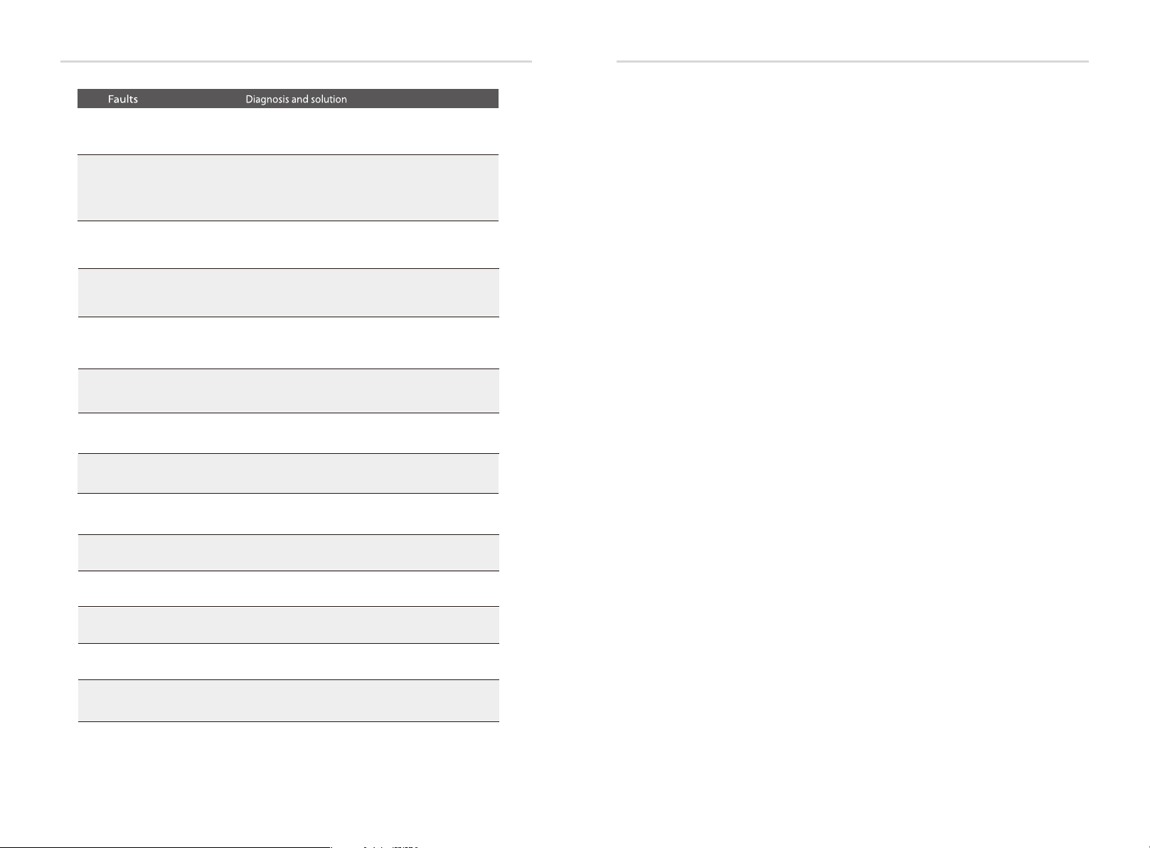
9. Troubleshooting
9.1 Trouble shooting
This section contains information and procedures for solving possible problems
with X1-AC inverters, and provides you with troubleshooting tips to identify and
solve most problems that could occur with the X1-AC inverters.
This section will help you narrow down the source of any problems you may
encounter. Please read the following troubleshooting steps.
Check warnings or fault messages on System Control Panel or Fault codes on the
inverter information panel. If a message is displayed, record it before doing
anything further.
Attempt the solution indicated in below table.
AC10M Volt Fault
DCI OCP Fault
SW OCP Fault
RC OCP Fault
Isolation Fault
The grid voltage is out of range for the last 10 Minutes.
• The system will back to normal if the grid is back.
• Or seek for help from us.
DCI over current protection Fault.
• Wait for a while to check if back to normal.
• Or seek for help from us.
Over current fault detected by software.
• Wait for a while to check if back to normal.
• Turn off the battery and grid , reconnect them.
• Or seek for help from us.
DCI over current protection Fault.
• Please check if the insulation of electric wires are damaged.
• Wait for a while to check if back to normal.
• Or seek for help from us.
Isolation Fault
• Please check if the insulation of electric wires are damaged.
• Wait for a while to check if back to normal.
• Or seek for help from us.
Troublesh ootin g
54
TZ Protect Fault
Grid Lost Fault
Grid Volt Fault
Grid Freq Fault
Meter Fault
Bus Volt Fault
Bat Volt Fault
Over current Fault.
• Wait for a while to check if go back to normal status.
• Disconnect battery and reconnect it.
• Or seek help from us, if can not go back to normal state.
Grid is Lost.
• Please wait for a while and system will reconnect if the utility is back to normal.
• Please check whether the cable connection at AC side is normal or not.
• Or seek help from us.
Grid Voltage Out of Range
• Please wait for a while and system will reconnect if the utility is back to normal.
• Please check whether the grid voltage is in the normal range.
• Or seek help from us.
Grid Frequency Out of Range
• System will reconnect if the utility is back to normal.
• Or seek help from us.
Meter Fault.
• Please check if the meter is abnormal working.
• Or seek for help from us if can not go back to normal.
Bus Voltage Out of Normal Range
• Disconnect battery, reconnect it.
• Or seek help from us, if can not go back to normal state.
Battery Voltage Fault
• Check if the battery input voltage.is within the normal range
• Or seek help from us.
Temp Over Fault
BatConDir Fault
Sample Fault
BMS Lost
Inter Com Fault
Fan Fault
AC H CT Fault
Temperature over the limitation
• Check if the envirement temperature is over limitation.
• Or seek help from us.
Battery Reverse Connection Fault
• Check if the positive pole and negtive pole of battery are connected
in a contrary way
• Or seek help from us.
The detection circuit Fault
• Disconnect battery, reconnect it.
• Or seek help from us.
BMS Communication Lost
• Check if the BMS cable is loose or broken.
• Or seek help from us, if can not go back to normal state.
Internal Communication Fault
• Turn off the battery and grid , reconnect them.
• Or seek help from us, if can not go back to normal state.
Fan Fault
• Turn off the battery and grid , reconnect them.
• Or seek help from us, if can not go back to normal state.
AC Current Sensor Fault
• Turn off the battery and grid , reconnect them.
• Or seek help from us, if can not go back to normal state.
55
Troublesh ootin gTroublesh ootin g
● If your inverter's information panel is not displaying a Fault light, check the
following list to make sure that the present state of the installation allows
proper operation of the unit.
— Is the inverter located in a clean, dry, adequately ventilated place?
Inv EEPR OM Fault
Inverter EEPROM Fault
• Turn off the battery and grid , reconnect them.
• Or seek help from us, if can not go back to normal state.
— Are the cables adequately sized and short enough?
— Are the input and output connections and wiring in good condition?
— Are the configurations settings correct for your particular installation?
— Are the display panel and the communications cable properly
connected and undamaged?
Contact SolaX Customer Service for further assistance. Please be prepared to
describe details of your system installation and provide model and serial number
of the unit.
RCD Fault
Grid Relay Fault
OtherDevideFault
Residual Current Device Fault
• Check the impedance of AC output.
• Disconnect battery, reconnect it.
• Or seek help from us, if can not go back to normal state.
Grid Relay Fault
• Disconnect grid and battery, reconnect them.
• Or seek help from us, if can not go back to normal state.
Other Devide Fault
• Disconnect grid and battery, reconnect them.
• Or seek help from us, if can not go back to normal state.
Mgr EEPROM Fault
BMS_External_Err
BMS_TemHigh
BMS_TemLow
BMS_CellImblance
BMS_Internal_Err
BMS_OverVoltage
BMS_LowerVoltage
BMS_ChargeOCP
BMS_DischargeOCP
Manager E EPROM Fault.
• Turn off the battery and grid , reconnect them.
• Or seek for help from us if can not back to normal.
Battery Fault-extarnal fault
• Please contact battery suppiler.
Battery Fault-over-temperature fault
• Please contact battery suppiler.
Battery Fault-under-temperature fault
• Please contact battery suppiler.
Battery Fault-cell imbalance fault
• Please contact battery suppiler.
Battery Fault-intarnal fault
• Please contact battery suppiler.
Battery Fault-overvoltage fault
• Please contact battery suppiler.
Battery Fault-undervoltage fault
• Please contact battery suppiler.
Battery Fault-charge overcurrent fault
• Please contact battery suppiler.
Battery Fault-discharge overcurrent fault
• Please contact battery suppiler.
56
57

Decommis sioni ng Troublesh ootin g
9.2 Routine maintenance
Inverters do not need any mainteinance or correction in most condition,but if
the inverter often loses power due to overheating,this can be the following
reason:
● The cooling fins on the rear of house are coverd by dirts.
Clean the cooling fins with a soft dry cloth or brush if necessary.
Only trained and authorized professional personnel who are familiar with the
requirements of safety was allowed to perform servicing and maintenance
work.
Safety checks
Ø
Safety checks should be performed at least every 12 mouths, please contact
manufacturer to arrange qualified person who has adequate training,kownledge,
and practical experience to perform these tests.(Please kindly noted this action is
not covered by warranty).The data should be recorded in an equipment log.If the
device is not functioning properly or fails any of test,the device has to be
repaired.For safety check details ,refer to this manual,section 2 Safety instruction
and EC Directives.
Maintain Periodically
Ø
Only qualified person may perform the following works.
During the process of using the inverter,the manage person shall examine and
maintain the machine regularly.The concrete operations are follow.
1: Check that if the cooling fins on the rear of house are covered by dirts, and the
machine should be cleaned and absorbed dust when necessary.This work shall
be check time to time.
2: Check that if the indicators of the inverter are in normal state,check if the keys
of the inverter are in normal state,check if the display of the inverter is normal.This
check should be performed at least every 6 months.
3: Check that if the input and output wires are damaged or aged.This check
should be performed at least every 6 months.
4: You should keep the inverter panels clean and their security checked at least
every 6 months.
10. Decommissioning
10.1 Remove the Inverter
Disconnect the inverter from DC Input and AC output.
Wait for 5 minutes for de-energizing.
Disconnect communication and optional connection wirings.
Remove the inverter from the bracket.
Remove the bracket if necessary.
10.2 Packaging
Please pack the inverter with the original packaging.
If the original package is no longer available, you can also use an equivalent
carton that meets the following requirements.
Suitable for loads more than 30 kg.
With handle.
Can be fully closed.
10.3 Storage and Transportation
Store the inverter in a dry environment where ambient temperature keep
always between -20 °C - +60 °C. Take care of the inverter during the storage
and transportation,keep less than 4 cartons in one stack.
When the inverter or other related components need to be disposed. Have
it carried out according to local waste handling regulations. Please be sure
to deliver wasted inverters and packing materials to certain site, where can
assist relevant department to dispose and recycle.
58
59

 Loading...