

Page 1

Packing List
Quick Installation Guide
Solax Box 3.0
Wi-Fi antenna x1
I
Battery Installation
BMU Installation
Wi-Fi connector x1
Quick Installation Guide x1
Warranty card x1
item①
item②
Expansion tubes x2
Expansion screws x2
M6 washers x2
item③
item④
item⑤
Bracket x2
Battery Guard x1
item⑥
item⑦
item⑧
BMS cable x1
item⑨
Box Installation
- Tighten the expansion tubes.
- Pass the expansion screws though the M6 washers,
then screw the expansion screws.
- Place Solax Box 3.0 against the ground.
- Drill holes withφ10 drill.
- Depth: at least 50mm
Connectors inside the Box
+
-
- Overview of connectors inside the Solax Box 3.0.
(Wiring of the connectors inside the box has been completed upon delivery.)
item③
item④
item⑤
LG Connectors
X 2 pairs
BAT Connector
Pv1Pv1+
Pv2Pv2+
EPS Connector
AC Connector
+
-
Application
Application
Connectors
Connectors
Notes:
- Affix the empty box on the wall rst before proceeding any installation. It will be too dangerous to move as the box tting with batteries and inverter will
overweigh box-handle’s bearing limit.
- Clean or replace the ventilation lters every three months.
CAN/RS485
CAN2
CAN/RS485
CAN2
CAN/RS485
CAN2
CAN/RS485
CAN2
CAN2
SWITCH
- Connect LG connectors
into the jacks on the battery.
For one battery
For two batteries
(in parallel)
- Find cable inBMS Solax
Box 3.0 packaging.
- Insert the “LG-Bat” side of
the “BMS” cable into the “CAN/
RS485" port on the battery
(The “Solax” side is to be related
to BMU in chapter V).
- Find intra-rack network
cable in battery packaging.
- Insert it into “CAN2" ports
on the batteries respectively.
- Place the battery into the Solax Box 3.0.
- Install the battery guard.
Solax Box 3.0 can be equipped with two models of batteries respectively.
M48063P3S
M48126P3S
Battary
Nominal
Voltage
Nominal
Capacity
Dimension
51.8V 51.8V
63Ah 126Ah
M48063P3S
445*110*338.8mm 445*110*586.6mm
M48126P3S
Nominal
Energy
3.262kWh 6.524kWh
Maximum
Current
63A 63A
CAN/RS485
CAN2
item⑨
item⑧
item⑨
LG-Bat
LG-Bat
- Insert the key.
- Open the door.
- If the space is too narrow to fully open the door, you are
able to remove the door. Please note that the door can only
be removed when opened 30 degrees or more.
- Dismantle the ground wire before removing the door.
- Remove the safety bezel.
30°
Comm unica tion:
- Find t he BMS ca ble whi ch has
been c onnec ted to th e Batte ry
(cha pter IV ).
- Ins ert the “So lax” sid e of BMS
cabl e into th e “BMS” por t on the
BMU.
Battery Power Supply:
- Find BAT Connector inside the box (chapter III).
- Insert BAT connector into “BAT” port on the
BMU.
- Connection between BMU and Battery (Wiring of BMU side).
- Match the BMU with bracket.
Communication:
- Find CAN connector in BMU Packaging.
- Insert one side of the connector into “CAN”
port on the BMU ( The other side is to be related
to SK-TL in chapter VI).
BUS Connection:
- Find BUS Connectors in BMU Packaging.
- Connect BUS connectors to “BUS” port on the
BMU (The other side is to be related to SK-TL in
chapter VI).
- Connection between BMU and SK-TL (Wiring of BMU side).
BAT Connector
Sol
ax
item⑨
Corrugated Tubing x1
item⑩
Page 2
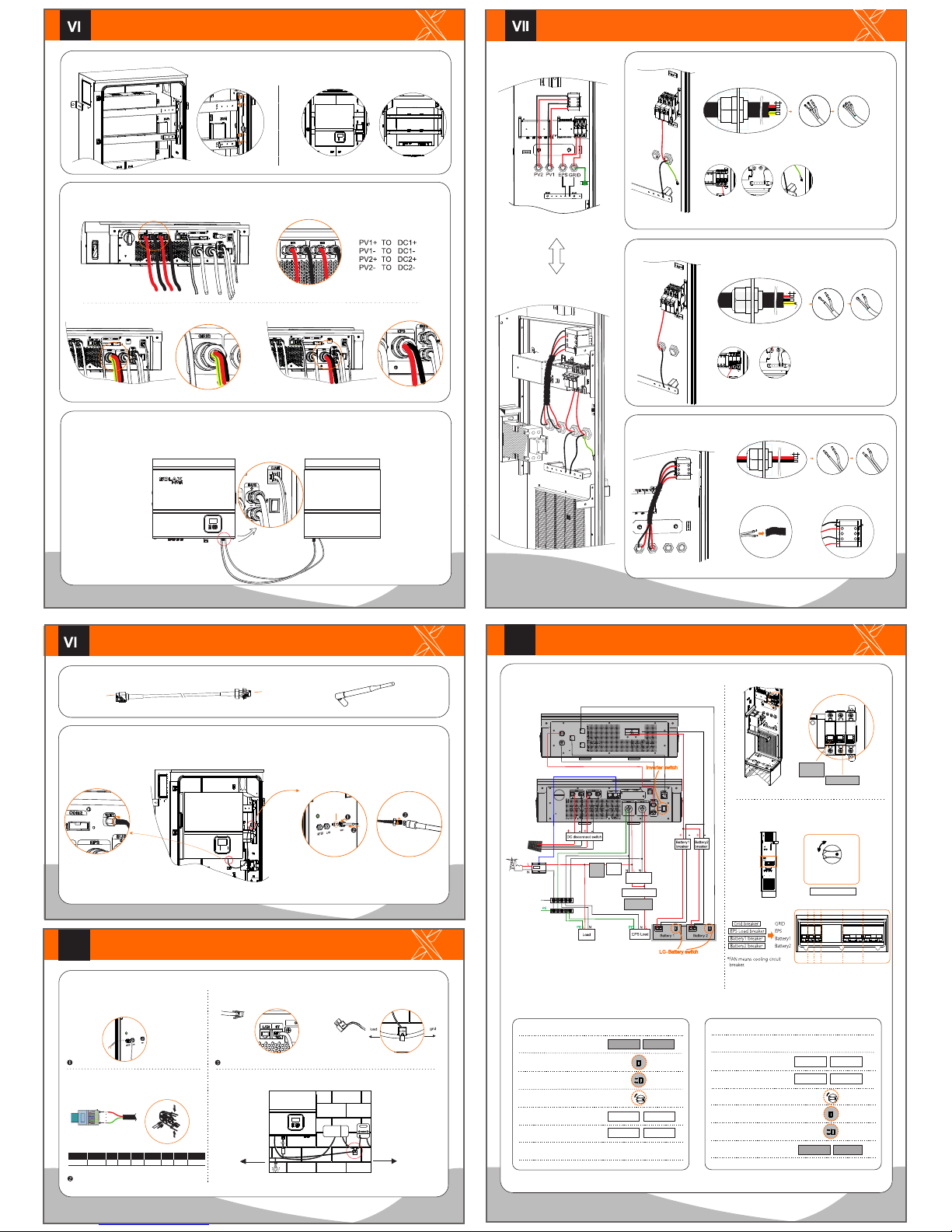
SK-TL Installation
614.00240.03
GRID/EPS LOAD/PV Connection
EPS Load connection steps (EPS Load cable size: 4~5mm):
2. Make EPS Load wires.
1. Insert EPS Load cable into “EPS” port.
3. Connect wires to the EPS Load circuit breaker (inside the box) and
N-bar respectively.
12mm
reserved
PV connection steps (Please use the PV special cables):
12mm
1. Insert PV+ and PV- cables into PV ports.
2. Make PV wires.
4.Co nnect w ires to t he DC
disco nnec t switc h.
12mm
Grid connection steps (AC cable size: 4~5mm):
2. Make AC wires.
1. Insert AC cable into “GRID” port.
3. Conn ect wi res to the G rid cir cuit br eaker ( insid e the box ), N-ba r and
groun d termi nal res pecti vely.
SK-TL
BMU
Connection between SK-TL and BMU (Wiring of SK-TL side).
- Find the BUS connectors and CAN connector that has already been inserted into the ports on the BMU.
- Insert RJ45 side of the CAN connector into “CAN” port on the SK-TL.
- Insert the BUS connectors into the “BUS” port on the SK-TL.
- Match SK-TL with the bracket.
- Install the bracket.
Conn ectio n betw een SK-TL a nd circu it brea kers ( Wirin g of SK-TL s ide).
- Find P V conne ctors , AC conne ctor a nd EPS co nnect or insi de the box .
- Plug P V conne ctors t o DC por ts on the S K-TL by num bers.
- Plug AC connector to “GRID” port.
- Plug EPS connector to “EPS” port.
item⑥
item⑦
*Notes: Please refer to Quick Installation Guide or User Manual in SK-TL packaging for system setting.
Wi-Fi Connection
CT Installation
II
IX
- Find Wi-Fi connector and Wi-Fi antenna in Solax Box 3.0 packaging.
- Tighten the tube side of the Wi-Fi connector
with the “WIFI” port on the SK-TL clockwise.
- Tighten the screw side of the Wi-Fi
connector with Wi-Fi antenna through
the “WIFI” gland on the box.
(Make sure the hinge of the Wi-Fi antenna
is inside the box.)
item①
tube
screw
item②
*Note: Please refer to Wi Setting Guide in SK-TL packaging for Wi-Fi setting.
hinge
item②
CT connection steps:
- Abbreviated drawing of the CT connection
- Find CT in SK-TL packaging.
- Cut off the RJ45 connector.
- Insert the CT wire though the “Meter” gland.
- Connect CT wire to a RJ45 connector.
- Please follow the sequence below:
Pin
1
CT
Red wire
2 3 4 5X76X8
X X X X
Green wire
L
- Hang the CT on the Live line which
connects to the electric meter
(Arrow towards the public grid).
- Insert RJ45 to “CT” port on the SK-TL.
LOAD
GRID
Home
Electric
Meter
Meter Box
Main
Switch
Battery Inverter
Main Switch
Pv1+
Pv1-
Pv2+
Pv2-
3.Pas s the wir es thro ugh the
corr ugated t ubing .
item⑩
Wiri ng Diag ram
Pict orial Wi ring Di splay
Ground
N-Bar
System Power On/Off Procedure
X
DC Disconnect Switch & Circuit Breakers
(Outside the box):
Circuit Breakers (Inside the box):
EPS Load
breaker-IN
Grid breaker-IN
EPS GRID Reserved
Step 7: Switch on AC “Main Switch (Battery Inverter & EPS Supply)”
located in the Meter box.
Step 6: Switch on Grid & EPS Load
& cooling circuit breakers.
Battery1 breaker Battery2 breaker
Grid breaker
EPS Load
breaker
Battery1 breaker Battery2 breaker
Grid breaker
EPS Load
breaker
Step 5: Switch off LG-Battery switch.
Step 6: Switch off Inverter switch.
Step 7: Switch off Grid & EPS load
circuit breakers inside the box.
PV system restart procedures:
PV system shutdown procedures:
Step 1: Switch on Grid & EPS load
circuit breakers inside the box.
Step 4: Switch on DC disconnect switch.
Step 2: Switch on LG-Battery switch.
Step 3: Switch on Inverter switch.
Step 5: Switch on Battery1 & 2
circuit breakers.
Step 4: Switch off DC disconnect switch.
Step 3: Switch off Battery1 & 2
circuit breakers.
Step 1: Follow the “Battery Shutdown Procedure” to turn off the AC
“Main Switch (Battery Inverter & EPS Supply)” located at the Switchboard.
Step 2: Switch off Grid & EPS Load
& cooling circuit breakers.
EPS Load
breaker-IN
Grid breaker-IN
EPS Load
breaker-IN
Grid breaker-IN
DC disconnect switch
DC SWITCH
ON
OFF
GRID
Battery1
EPS FAN
Battery2
Circuit Breakers outside the Box
System wiring diagram:
Items highlighted in grey should be performed inside the box.
GRIDEPS
PV1PV2
ON
OFF
METER
WIFI
LAN
GRID
Battery1
EPSFAN
Battery2
*Notes: The system wiring diagram does not include the cooling circuit. The cooling circuit has
already been connected upon delivery.
The cooling circuit will run automatically when the ambient tempreture of the box is
over 45℃.
SK-TL
BMU
BUS
CAN
BMS
TEMP
BAT
+
-
+
-
EPS Contacter
N-BAR
Grid
breaker
-IN
Grid
breaker
EPS Load breaker
EPS Load
breaker-IN
ON
OFF
ON
OFF
*Notes: The alarm light will emit red when the inverter is faulty.
 Loading...