

I
Not e: T he Q ui ck I ns ta llation Gui de brie fly des cribe s requi re d in st al lation step s. I f yo u hav e any quest ions, r ef er t o the Us er
Man ual enc losed with the BM S for mor e de ta il ed i nfo rm at io n.
Packing List (BMS)
Quick Installation Guide
—— Triple Power Lithium-ion Battery
II
OneBattery Module (HV10230 ×1):
Power Cable (690mm) x1
COMM Cable (600mm) x1
Accessories (1) of thethree and four Battery Modules (HV10230×3/4):
Power Cable (1200mm) x1
COMM Cable(1200mm) x1
Accessories (2) of the three and four Battery Modules (HV10230×3/4):
Packing List (Battery Module)
M4 Screw x2
M4 Screw x2
Expansion Bolt x2
Base M x1 ounting
Battery Module x1
Cover Plate x1
Snap-fit x2
Guard Ring x4
Quick Installation Guide
--Triple Power Lithum-ion Battery
Quick Installation Guide x1
Quick Installation Guide
--Triple Power Lithum-ion Battery
Accessories of Wall bracket x1
Quick Installation Guide x1
Cha rging C ab le ( -) x1 ( 2m)
Cha rging C ab le ( +) x1 ( 2m)
Wal l Bra cke tx1
M4 Sc rew x 2
Expansion Bolt x2
III
Ens ure tha t th e in st al la tion location m eets the fo ll owing condi tions :
The building is designed to withstand earthquakes
ŸŸŸŸŸŸŸŸŸŸ
The location is far the sea to avoid salt water and humidity, 1000mfrom over
Ÿ
The floor is flat and level
Ÿ
There are no flammable or explosive materials, at a minimum of 0.9m
Ÿ
The ambience is shady and cool, away from heat and direct sunlight
Ÿ
The temperature and humidity remain at a constant level
Ÿ
There is minimal dust and dirt in area
Ÿ
There are no corrosive gases present, including ammonia and acid vapor
Ÿ
Where charging and discharging, the ambient temperature ranges from 0°C to 45°C
Ÿ
In pr ac ti ce , the requi remen ts o f ba tt er y in st allatio n may be di ff erent d ue to enviro ment an d locatio ns.
In th at case, fo ll ow up the e xact re qu ir em en ts of the loc al laws a nd s ta nd ar ds.
Power Cable(0.12m) x1
M5 Screw x2
Expansion Bolt x2 Expansion Screw x2
Guard Ring x2
Base M x1 ounting
Installation Prerequisites
CAN Cable x1 (2m)
COMM Cable x1 (0.2m)
Flat Gasket x2
BMS x 1
NOTE!
The Triple P ower batt er y modul e is rate d at I P6 5 an d th us c an b e install ed outd oors as w ell as in doors . Howeve r,
ifin stall ed outd oors, d o not all ow the ba tt er y pa ck to be ex po se d to d irect sunligh t and moi sture .
Rotation Wrench x1
Rin g Termi nal x1
Triple Power Lith ium-i on Batt ery
User Manual
30Ah
Copyright Declaration
The copyright of this manual belongs to SolaX Power Co.,Ltd.. Any corporation or
individual should not plagiarize, partitially copy or fully copy(including software,etc.),
and no reproduction or distribution of it in any form or by any means. All rights
reserved.
SolaX Power Co.,Ltd,.reserves the right of final interpretation. The information is
User Ma nual x1
Power Cable(1200mm) x1
Power Cable(1800mm) x1
IV
Note:The two power cables need to be purchased separately
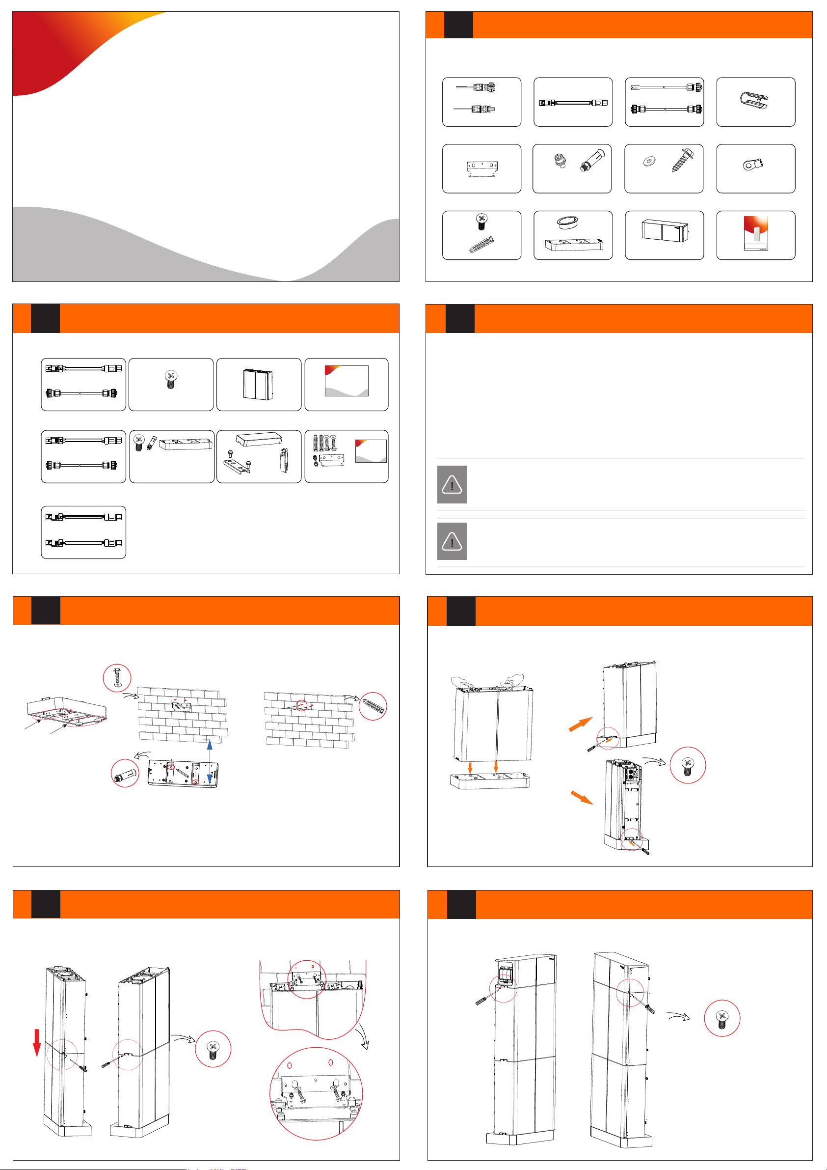
Floor/Wall Mounting
Make sure the wall is strong enough to withstand the weight of battery.
-Adjust the balance
- Mark the postion of the holes
- Drill holes(at least 80mm) with driller
(1
93±2) mm
-Tighten the expansion screw sleeve
NOTE!
If th e ambie nt temp er at ure exc ee ds t he operat in g ra ng e, th e batte ry p ack wil l stop op er at in g to prot ec t it se lf .
The o ptima l tempe ra tu re ra nge for o pe ra ti on is -10°C to 50 ° Fre qu en t exp osure t o ha rs h te mpera tures m ay C.
det er io ra te the per formanc e and lifet im e of t he b at tery m odule.
V
Battery Module Installation to Base Mounting
Step 3: Match the battery with base mounting
Pla ce the BMS on t op o f th e ba tt er y mo du le and affix it w ith M4 screws using an L -type w rench . En su re t hat the BMS and
bat tery unit a lign on m atchi ng s id es a s sh own i n the dia gram be lo w.
VI
Battery Module Installation to Module
For two battery s:module
Place the se cond one on top of the module and two si des a re locked wi th M4 s crews .
·
Fix the battery module an d wal l bracket with expa nsi on bolts.
·
Note : One battery module or co nne cted to the BMS, nee d to be i nst all ed a bracket to fix .
VII
BMS Installation to Battery Module
Match the BMS to the battery modules
Place the BMS on top of the module and tw o sid es are locke d wit h M4 screws(N).
·

VIII
B+
B-
COMM1
Connecting Cables to Inverter
IX
Connecting Cables to One Battery Module
BMS to I nverter:
BAT+ to BAT+(A:2m),
BAT- to BAT-(B:2m),
CAN t o CAN(D:2m )
X
Connecting Cables to Two Battery Modules
GND
To Inverter
+
BAT+
-
BAT-
CAN
Step1. Strip the cable(A/B:2m) to 15mm.
Step2. Insert the stripped cable up to the stop (negative cable for DC plug(-) and
positive cable for DC socket(+) are live). Hold the housing on the screw
connection.
Step3. Press down the spring clamp until it clicks audibly into place (You should be
able to see the fine wie strands in the chamber)
Step4. Tighten the screw connection(tightening torque:2.0±0.2Nm)
Step2.
screw connection
DC plug housing(-)
Step3. Step 4.
chamber
spring
wire strands
screw connection
DC socket housing(+)
Ensure that both ends of the cables are connected to the correct connector, which are on the
right side of the BMS and battery module.
Ÿ
BMS to Slave1: B+ to B+(C:1200mm), B- to B-(A1:690mm), COMM to COMM1(E:200mm)
The BMS and battery modules need to be grounded.
XI
Connecting Cables to Three Battery Modules
+
-
Install a fixed wall bracket on the battery module, and thencheck to make sure the connections
are securely locked.
BMS
BMS to Slave1:
B+ to B+ (C:120mm);
COMM to COMM1 (E:0.2m)
BMS to Slave2:
B- to B- (A1:690mm)
Slave1 to Slave2:
B- to B+ (A1:690mm); COMM2 to
COMM1 (B1:600mm)
XII
The BMS and battery modules need to be grounded.
Between battery modules need to be grounded.
BMS to Slave1:
B+ to B+ (C:120mm); COMM to
COMM1 (E:200mm);
BMS to Slave3:
B- to B- (A1:1.8m); Get the cables
through corrugate pipe.
Slave1 to Slave2:
B- to B+ (A1:690mm); COMM2 to
COMM1 (B1:600mm)
Slave2 to Slave3:
B- to B+ (A2:1.2m); COMM2 to COMM1
(B2:1.2m); Get the cables through
corrugate pipe.
Connecting Cables to Three Battery Modules
Slave3
Slave1
Slave2
Slave1
Slave2
Install a fixed wall bracket on the battery modules and the cover plate of the third battery module.
(2)
(3)
XIII
(1)
Connecting Cables to Four Battery Modules
Install the fixed wall brackets on the battery modules
And thencheck to make sure the connections are securely locked.
BMS to Slave1:
B+ to B+ (C:120mm);COMM to COMM1 (E:200mm);
BMS to Slave4:
B- to B- (A3:1.2m), Get the cable through corrugate pipe.
Slave1 to Slave2:
B- to B+ (A1:690mm);COMM2 to COMM1 (B1:600mm);
Slave2 to Slave3:
B- to B+ (A3:1.2m);COMM2 to COMM1 (B2:1.2m);
Slave3 to Slave4:
B- to B+ (A1:690mm) and COMM2 to COMM1
(B2:1.2m).
Get the cables through corrugate pipe.
The BMS and battery modules need to be grounded.
Between battery modules need to be grounded.
XIV
The two ends of the corrugated
pipe need to be protected with guard rings.
Connecting Cables to Four Battery Modules
Slave4
Slave3
BMS
Slave1
Slave2
XV
Commissioning
If all batteries are used for the installation, follow these steps for
beginning operation.
Verify the model number of each battery module to ensure thatthey are allthe
same model.
Once all battery module(s) are installed, follow these steps for beginning operation:
1) Open the cover board of theBMS
2) Move the circuit breaker switch to theON position
3) Press the POWER buttonto turn on the T-BAT system
4) Turn on the AC switch of inverter
B+
COMM1
B-
COMM2
614.00520.00
 Loading...