


品名
材料
料号
单位
页次
设计
审核
核准
技术要 求:
1.封面 封底157g铜 版纸覆亚光 膜彩打,内 部普通纸黑 白印刷正反 打印
2.未注 公差:±1
3.图面 、字体印刷 清晰、无毛 边
4.字体 颜色为PANTO NE Blac k C,无边框, 底色为白色
5.符合R oHS要 求
X1- Mini说明 书
614 .00 .01098
浙江艾罗 电源有 限公司
朱伟 20 16/6/ 28
朱娴红 2 016/6 /28
朱娴红 2 016/6 /28
21 0.0 0 mm
28 5. 0 0 mm
NA
REV. REV.
Description Description
0.0 1.0
1.0
0.0
0.0
0.0
0.0
0.0
0.0
0.0
1.0
V0.0首次发行 V0.1应BV认证要求修改文档
V0.1软件修改,升级固件的方式改动
朱伟 2016/1/25 朱伟 2016/6/28
朱伟 2016/7/5
朱伟 2016/3/15
朱伟 2016/3/28
朱伟 2016/4/5
朱伟 2016/4/21
朱伟 2016/4/26
朱伟 2016/5/12
朱伟 2016/5/12
朱伟 2016/6/20
V0.1增加updating和灯显
V0.2 Page7:DRM和RS 485调换位置
V0.3 将1000w改成1100w
V0.4 P21更改updating灯显;
将所有X1-mini改为X1&封皮修改。
V0.5 GFCI fault 改为rcd/rc fault;
usb烧录要求:PV输入电压大于100V。
V0.6 THD改成小于2%.
V0.7 P17 AC连接线线径2mm²改成12AWG
V0.1 机壳增加接地,修改图、安装部分。
品名
料号
单位
X1- Mini说明 书
614 .0009 8.01
页次
浙江艾罗 电源 有限公 司
Sola X Power Co ., Ltd.
Copy Declaration
The co pyrig ht of thi s manua l belon gs to Sol aX
Power C o.,Ltd .. Any cor pora tion or
indi vidua l shoul d not pla giari ze, par titia lly cop y or
X1 Se ries
User Manual
1.1kw~2.0kw
X1-2.0-S-D
X1-2.0-S-N
0.1
V0.5 Page23 升级ARM文件的格式
由".hex"改为".usb"
朱伟 2016/7/22
614 .0009 8.01
X1 Series
User Manual
1.1kw~2.0kw
Copy Declaration
The c opyri ght of th is manu al belo ngs to So laX Powe r Co.,Lt d.. Any c orpor ation o r indiv idual
sho uld not p lagia rize, p artit ially o r fully c opy(i nclud ing sof tware ,etc. ), and no re produ ction o r
dis tribu tion of i t in any fo rm or by any m eans. A ll righ ts rese rved. S olaX Po wer Co., Ltd,. reser ves
the r ight of f inal in terpr etati on.

Contents
1 NOTES ON THIS MANUAL
2 SAF E T Y
3 INT RODUCTI O N
4 TECHN I CAL DATA
5 FUN C T ION
6 INS TALLATION
7 OPE R ATIO N ME T HOD
8 TROUB L ESHOOTIN G
1.1 SCOP E OF VAL IDITY
... ..... ..... ..... .. .. ............. .. .. ............. .. ............. ..... ...
... ..... ..... ..... .. .. ............. .. .. ............. .. ............. ..... ..... ..... ..
... ..... ..... ..... .. .. ............. .. .. ............. .. ............. ..... ..... ..... ..
... ..... ..... ..... .. .. ............. .. .. ............. .. ............. ..... ..... ..... ..... .. .. ............. ..
... ..... ..... ..... .. .. ............. .. .. ............. .. ............. ..... ..... ..... .
... ..... ..... ..... .. .. ............. .. .. ............. .. ............. ..... ...
... ..... ..... ..... .. .. ............. .. .. ............. .. ............. ..... ..... ..
... ..... ..... ..... .. .. ............. .. .. ............. .. ............. ..... ..... ..... ..... .. .. ......
... ..... ..... ..... .. .. ............. .. .. ............. .. ............. ..... ..... ..... .....
... ..... ..... ..... .. .. ............. .. .. ............. .. ............. ..... ..... ..... ..... .. .. .
... ..... ..... ..... .. .. ............. .. .. ............. .. ....
... ..... ..... ..... .. .. ............. .. .. ............. .. ............. ..... ..... ..... ..... .
... ..... ..... ..... .. .. ............. .. .. ............. .. ............. .....
... ..... ..... ..... .. .. ............. .. .. ......
... ..... ..... ..... .. .. ............. .. .. ............. .. ............. ..... .....
... ..... ..... ..... .. .. ............. .. .. ............. .. ............. .
... ..... ..... ..... .. .. ............. .. .. ............. .. ............. ..... ..... ..
... ..... ..... ..... .. .. ............. .. .. ............. .. ........
... ..... ..... ..... .. .. ............. .. .. ............. .. ............. ....
... ..... ..... ..... .. .. ............. .. .. ............. .. ............. ..... ...
... ..... ..... ..... .. .. ............. .. .. ............. .. ............
... ..... ..... ..... .. .. ............. .. .. ............. .. ............. ..... ..... ..... ..... .. .. .....
... ..... ..... ..... .. .. ............. .. .. ............. .. ............. ..... ..... ..... ..... .. .. .
... ..... ..... ..... .. .. .............
... ..... ..... ..... .. .. ............. .. .. ............. .. ............. ..... ..... ..... ...
... ..... ..... ..... .. .. ............. .. .. ....
... ..... ..... ..... .. .. ...........
... ..... ..... ..... .. .. ............. .. .. ............. .. ....
... ..... ..... ..... .. .. ............. .. .. ............. .. ............. ..... ..... ..... .
... ..... ..... ..... .. .. ............. .. .. ............. .. ....
... ..... ..... ..... .. .. ............. .. .. ............. .. .........
... ..... ..... ..... .. .. ............. .. .. ............. .. .....
1.2 TARG ET GRO UP
1.3 SY MBO LS US ED
2.1 AP PROPR IATE U SAG E
2.2 IM POR TAN T SAF ETY INS TRU CTI ONS
2.3 PE CONN ECT ION A ND LE AKAGE CU RRENT
2.4 EX PLANAT ION OF S YMBOL S
3.1 BA SIC F EATU RES
3.2 T ERM INA LS OF PV IN VER TER
3.3 DI MENSI ON AN D WE IGH T
4.1 DC I NPU T
4.2 AC O UTPUT
4.3 EF FICIE NCY, SAF E T Y A ND PR OTECTI ON
4.4 GE NERAL DATA
6.1 PACK AGI NG
6.2 IN STALLATIO N PRE CAUTI ON
6.3 PR EPARAT ION
6.4 IN STALLATIO N STE PS
6.5 CONN ECTI ONS OF THE X 1 SYS TEM
6.6 RU N TH E I NVE RTE R
7.1 IN DICATOR PAN EL
7.2 IN DICATOR INF ORM ATI ON
8.1 TOU BOL ESHOOTI NG
8.2 RO UTINE MA INT ENA NCE
01
01
01
01
02
02
04
06
06
08
08
09
10
11
11
11
12
12
13
14
14
14
15
15
17
25
26
26
27
30
30
32

Note!
Note provides tips that are valuable for the optimal operation
of your product.
X1- 1.1-S -N
X1- 1.1-S -D
X1- 1.5-S -N
X1- 1.5-S -D
X1- 2.0-S -N
X1- 2.0-S -D
Ple as e store thi s ma nu al where it w il l be a ccessible a t all tim es.
Note: “1.1” means 1.1kW. ”S” means “single” or one MPPT string. “D” means
with “DC Switch”, ”N” means without “DC Switch”.
9 DECOMM I SSION I NG
... ..... ..... ..... .. .. ............. .. .. ............. .. ............. ....
... ..... ..... ..... .. .. ............. .. .. ............. .. ............. ..... ...
... ..... ..... ..... .. .. ............. .. .. ..........
... ..... ..... ..... .. .. ............. .. .. ............. .. ............. ..... ..... ..... ..... .. .. .....
9.1 DE COMMI SSI ONI NG
9.2 STOR AGE A ND TRAN SPORTATION
9.3 DI SPOSA L
34
33
33
33
inverters.
2 Safety
2.1 Appropriate Usage
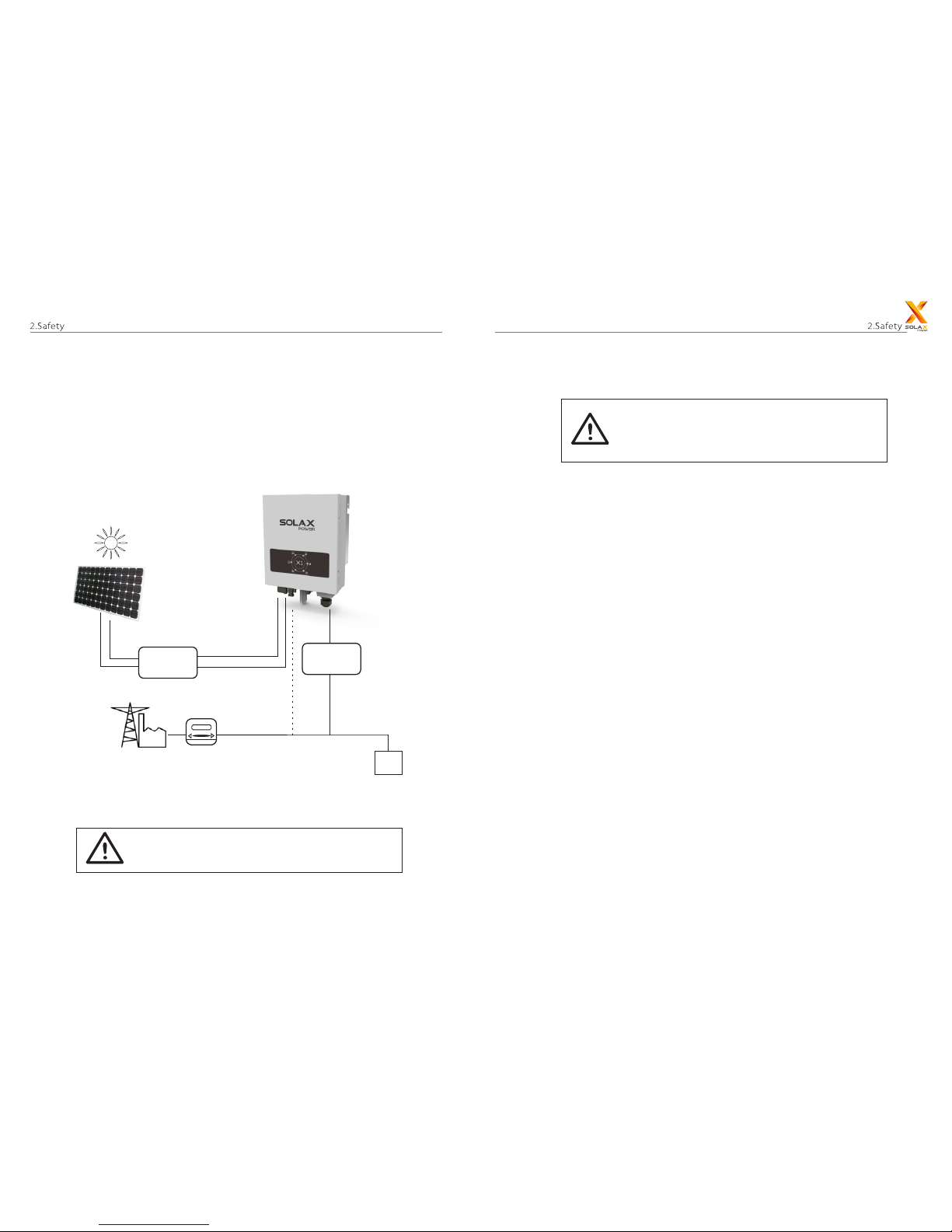
The X1Series are PV inverters which can convert the DC current of the P V
generator into AC current and feed it into the public grid.
Surge protection devices (SPDs) for PV installation
Over-voltage protection with surge arresters should be provided
when the PV power system is installed.
The gr id connec ted i nverter is not fitted with SPDs in both PV
input side and MAINS side.
WARNIN G!
For X1-1.1-S-N, X1-1.5-S-N, X1-2.0-S-N, external dc breaker must
be connected on the PV side.
CAUTION!
Induced surges are the most likely cause of lightning damage in majority or installations,
especially in rural areas where electricity is usually provided by long overhead lines.
Surge may be included on both the PV array conduction and the AC cables
leading to the building.
Specialists in lightning protection should be consulted during the end use application.
Using appropriate external lightning protection, the effect of a direct lightning
strike into a building can be mitigated in a controlled way, and the l ightn ing
current can be discharged into the ground.
Installation of S PDs to protect the inverte r against mechanical damage and
excessive stress include a surge arrester in case of a b uilding with ex terna l
lightning protection system (LPS) when separation distance is kept.
To protect the DC system, surge suppression device (SPD type2) should be fitted
at the inverter end of the D C cabling and at the array located between the
inverter and the PV generator, if the voltage protection level (VP) of the surge
arresters is greater than 1100V, an additional SPD type 3 required for surge protection
for electrical devices.
To protect the AC system, surge s uppression devices (SPD type2) should be
fitted at the main incoming p oint of A C supply (at t he co nsume r’s cutout ),
located between the inverter and the meter /dist ribution system; S PD ( test
impulse D1) for signal line according to EN 61632-1.
All DC cables should be installed to provide as short a run as possible, and positive
and negative cables of the string or main DC supply should be bundled
together. Avoid ing the creation of loops in t he system. This requirement for
short runs and bundling includes any associated earth bundling conductors.
Spark gap devices are not suitable to be used in DC circuits once conducting,
they won’t stop conducting until the voltage across their terminals is typically
more than 30 volts.
Lightning will cause a damage either from a direct strike or from surges due to a
nearby strike.
►
DC di stri butio n box
AC di stri butio n box
Ele ctric al
gri d
Ele ctric m eter,
bid irect ional
Loa d
PV a rray
Surg e arres tor
Fuse
DC br eaker
Surg e arres tor
Fuse
AC br eaker
2
3

2.2 Import an t Sa fety I ns tr uc ti on s
Dan ger!
Danger to life due to high voltages in the inverter!
All work must be carried out by qualified electrician.
The appliance is not to be used by children or persons with
reduced physical sensory or mental capabilities, or lack of
experience and knowledge, unless they have been given
supervision or instruction.
Children should be supervised to ensure that they do not play
with the appliance.
Cau tion!
Danger of burn injuries due to hot enclosure parts!
During operation, the upper lid of the enclosure and the
enclosure body may become hot.
Only touch the lower enclosure lid during operation.
Cau tion!
Possible damage to health as a result of the effects of radiation!
Do not stay closer than 20 cm to inverter for any length of time.
Not e!
Grounding the PV generator.
Comply with the local requirements for grounding the PV
modules and the PV generator. SolaX recommends connecting
the generator frame and other electrically conductive surfaces
in a manner which ensures continuous conduction and ground
these in order to have optimal protection of system and persons.
Warni ng!
Ensu re input DC voltage ≤Ma x. DC voltage .O ver vol tage
may cause permanen t damage to inve rte r or other losses,
whic h will not be i ncluded i n warrant y!
Warnin g!
Authorized service personnel must disconnect both AC and
DC power from X1-boost before attempting any maintenance
or cleaning or working on any circuits connected to the X1boost.
Prior to the application, please read this section carefully to ensure correct
and safe application. Please keep the user manual properly.
Use only attachments recommended or sold by SolaX. Otherwise may
result in a risk of fire, electric shock, or injury to person.
Make sure that existing wiring is in good condition and that wire is not
undersized.
Do not disassemble any parts of inverter which are not mentioned in
installation guide. It contains no user-serviceable parts. See Warranty for
instructions on obtaining service. Attempting to ser vice the X1-boost Series
inverter yourself may result in a risk of electric shock or fire and will void
your warranty.
Keep away from flammable, explosive materials to avoid fire disaster.
The installation place should be away from humid or corrosive substance.
Authorized service personnel must use insulated tools when installing or
working with this equipment.
PV modules shall have an IEC 61730 class A rating.
Never touch either the positive or negative pole of PV connecting device.
Strictly prohibit touching both of them at the same time.
The unit contains capacitors that remain charged to a potentially lethal voltage
after the MAINS and P V supply has been disconnected.
Hazardous voltage will present for up to 5 minutes after disconnection from
power supply.
CAUTION-RISK of electric shock from energy stored in capacitor,. Never operate
on the solar inverter couplers, The MAINS cables, PV cables or the P V generator
when power is applied. After switching off the PV and Mains, always wait for
5minutes to let the intermediate circuit capacitors discharge before you unplug
DC and MAINS couplers.
When accessing the internal circuit of solar inverter, it is very important to wait
45minutes before operating the power circuit or demounting the electrolyte
capacitors inside the device. Do not open the device before hand since the
capacitors time to sufficiently discharge! require
Measure the voltage between terminals UDC+ and UDC- with a multi-meter
(impedance at least 1Mohm) to ensure that the device is discharged before
beginning work (35VDC) inside the device.
Do not operate the inverter when the device is running.
Warning!
Risk of electric shock!
Warning!
4
5

2.3 PE Connection and Leakage Current
Island detection method
• The end-use application shall monitor the protective conductor by residual
current operated protective device (RCD) with rated fault current Ifn≤240mA
which automatically disconnects the device in case of a fault.
• DC differential currents are created (caused by insulation resistance and through
capacities of the PV generator). In order to prevent unwanted triggering during
operation, the rated residual current of the RCD has to be min 240mA.
The device is intended to connect to a PV generator with a capacitance limit of
approx 700nf.
High leakage current!
Earth connection essential before connecting supply.
WARNIN G!
• Incorrect grounding can cause physical injury, death or equipment malfunction
and increase electromagnetic.
• Make sure that grounding conductor is adequately sized as required by safety
regulations.
• Do not connect the ground terminals of the unit in series in case of a multiple
installation. This product can cause current with a d.c component, Where a residual
current operated protective (RCD) or monitoring (RCM) device is used for protection
in case of direct or indirect contact, only an RCD or R CM of type B is allowed
on the supply side of this product.
2.4 Explanation of Symbols
This section gives an explanation of all the symbols shown on the inverter and
on the type label.
Symbols on the Type Label
Symbol Explanation
CE mark.
The inverter complies with the requirements of the applicable
CE guildlines.
TUV certified.
RCM remark.
SAA certification.
Beware of hot sur face.
The inverter can become hot during operation. Avoid contact
during operation.
Danger of high voltages.
Danger to life due to high voltages in the inverter!
Danger.
Risk of electric shock!
Observe enclosed documentation.
The inverter can not be disposed together with the household waste.
Disposal information can be found in the enclosed documentation.
Do not operate this inverter until it is isolated from battery,mains
and on-site PV generation suppliers.
Danger to life due to high voltage.
There is residual voltage in the inverter which needs 5 min to
discharge.
• Wait 5 min before you open the upper lid or the DC lid.
No protection settings can be altered.
For Australia and New Zealand:
Electrical installation and maintenance shall be conducted by licensed
electrician and shall comply with Australia National Wiring Rules.
The island detection method for X1 series inverter is Active Frequency Drift
(AFD).
6
7
For United Kindom:
RS 485 communication interface.
PC remote control.
Update system by USB.
Plug and Play Pocket WiFi.
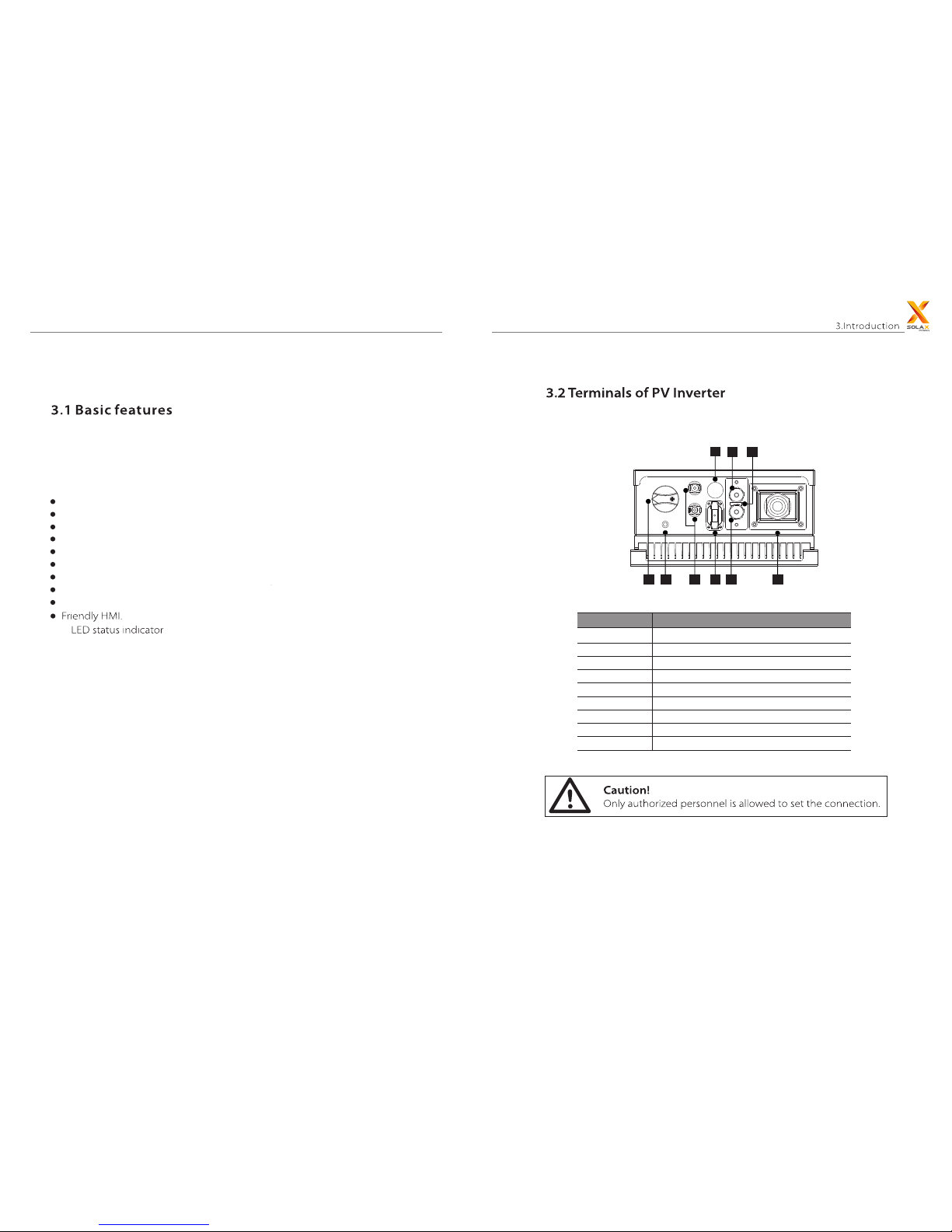
3. Introduction
A I B
D
CHE
F G
Object
A DC Switch (opt)
DC Connector
WiFi (opt)
E.F.Alarm (opt)
DRM
RS 485
USB for Update
AC Connector
Ground connection
B
C
D
E
F
G
H
I
Description
Congratulations on your purchase of a X1 Series inverter from SolaxPower
company.
The X1 Series inverter is one of the finest inverter on the market nowadays,
incorporating state-of-the-art technology, cost-effective, high reliability.
Optimal MPPT technology.
Advanced anti-islanding solutions.
Excellent protections.
IP 65 protection level.
Efficiency up to 97%.
THD < 3%.
Current (inrush) < 60A.
Maximum output fault current < A.50
Safe & Reliable: transformer-less design with software and hardware protection.
8
9
3. Instruction

Model
Net Weight
Gross Weight
7KG
9KG
7KG
9KG
7KG
9KG
Rated Output Power
Max.Output Power
Nominal Voltage
Max.Output Current
Maximum Output
fault current
On-grid Connection
Voltage Range
Frequency Range
Nominal Frequency
Power Factor
THD
24 8mm
35 0mm
124mm
X1-1.1-S-D
X1-1.1-S-N
X1-1.1-S-D
X1-1.1-S-N
X1-1.5-S-D
X1-1.5-S-N
X1-1.5-S-D
X1-1.5-S-N
X1-2.0-S-D
X1-2.0-S-N
X1-2.0-S-D
X1-2.0-S-N
1250W 1650W 2200W
400V
360V
70~380V 70~380V 70~380V
10A 10A 10A
12A 12A 12A
1
1
400V 400V
Model
Model
Max.PV Input Power
Max.PV Voltage
Max.PV Current
ISC PV
Nominal Voltage
MPPT Voltage Range
MPPT Tracking No.
No. of PV Input
1100VA
1100VA
1500VA
1500VA
2000VA
2000VA
Single-Phase
180-280V
220/230/240V
5.5A 7.5A 9.5A
7A 9A
11A
50/60Hz
44-55/55-65 Hz
0.8leading~0.8lagging
<2%
X1-1.1-S-D
X1-1.1-S-N
X1-1.5-S-D
X1-1.5-S-N
X1-2.0-S-D
X1-2.0-S-N
10
11

checking if PV array has enough power to
The corresponding state of the inverter shows as right. “ “
The corresponding state of the inverter shows as right. “ “
Under this mode, X1 series inverters convert PV array’s DC into AC and feed back
into grid.
The corresponding state of the inverter shows as right. “ “
If any fault/error occurs, the inverter will stop delivering power until the fault/error
is cleared. Some fault/error will auto recover, and some may need manual restart.
If inverter passed load-dump test and no error/fault occurs, start checking to
deliver power.
feedback into grid.
Operation Mode
[Waiting Mode]
[Checking Mode]
[Fault Mode]
It is normal that the inverter decreases the power output in
the condition of thermal protection, but if this phenomenon
occurs frequently, you need to check the heatsink, or
consider putting the inverter in the place where have better
air ow. If output power decreases caused by electrical,
please ask for professional supports.
Euro - Efficiency
95.5%
97.1%
99.9% 99.9%99.9%
96.5%96%
97.1%97.1%
YES
YES
YES
YES
YES
Max.Efficiency
Over Voltage Protection
Over Current Protection
DC isolation Impedance
Monitoring
MPPT Efficiency
Safety & Protection
Ground Fault Current
Monitoring
DC injection Monitoring
Protective Class
Net Dimension(W/H/D)
Wall-mounted
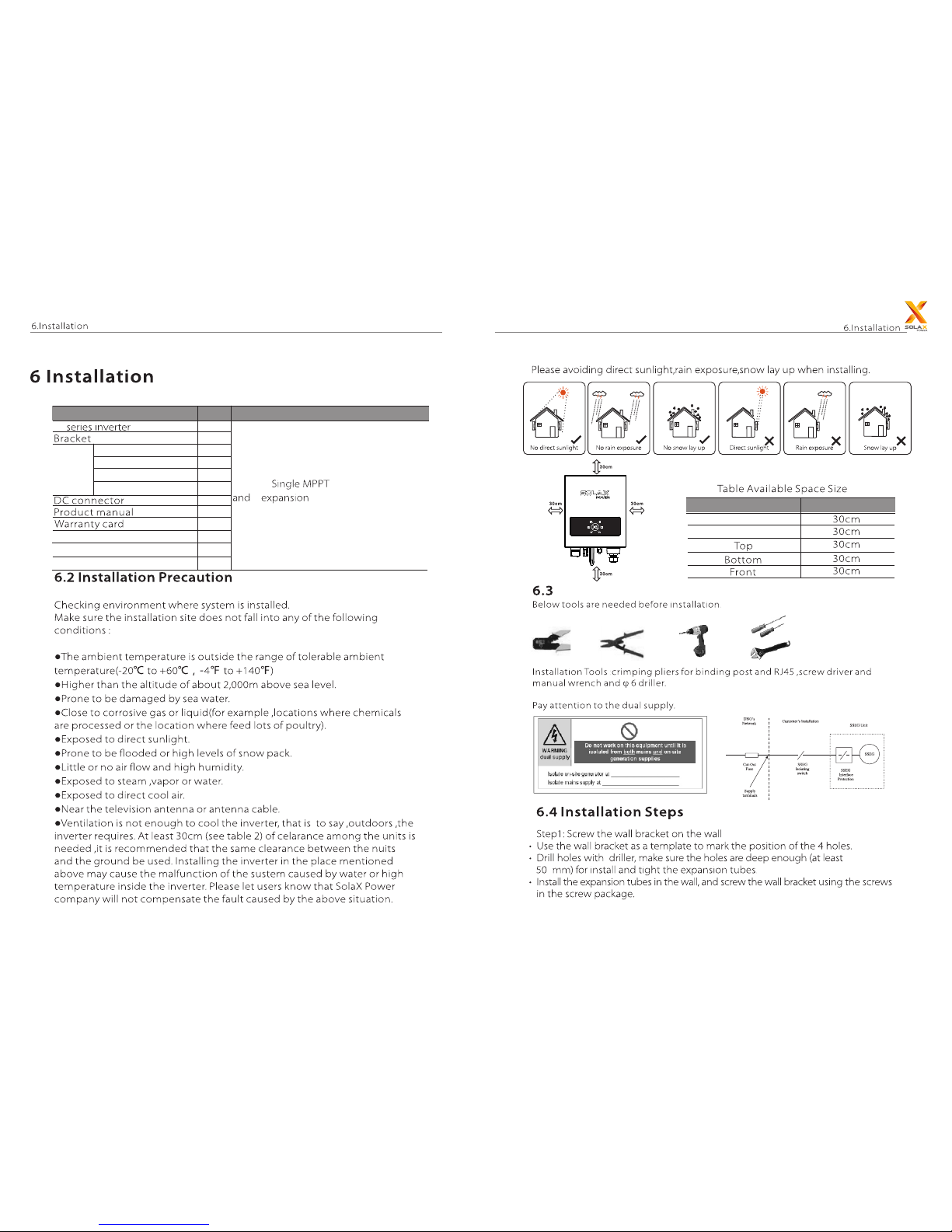
-20℃~ +60℃(derating at 45℃)
248*350*124mm
7kg
-20℃~ +60℃
0%~95%,no condensation
<2000m
IP 65 (for outdoor use)
Transformerless
0W
<10W
Natural Cooling
<30dB
RS485/WiFi(optional)/USB/DRM
5years(10 years optional)
Ⅱ / Ⅲ
Net Weight
Storage Temperature
Storage/Operation
Relative Humidity
Altitude
Installation
Operating Temperature
Range
Protection Level
Isolation Type
Night-time Consumption
Operating Loss
Cooling
Noise Level
Communication Interface
Standard Warranty
Pollution degree
Over voltage range(PV/AC)
Ⅱ
12
13
X1-1.1-S-D
X1-1.1-S-N
X1-1.5-S-D
X1-1.5-S-N
X1-2.0-S-D
X1-2.0-S-N
Model
X1-2.0-S-D
X1-2.0-S-N
X1-1.1-S-D
X1-1.1-S-N
X1-1.5-S-D
X1-1.5-S-N
Model
4. Technical data
Left
Right
2 expansion screws
1.1~2kw
AC terminal
Pocket WiFi (optional)
Description QTY Remark
X1
Position Min.size
3
1
1
1
1
2
1
2
2
1
1
1
Preparation
Expansion tube
Expansion screw
Cross recessed screw
Ring terminal
Screw
package
2
tubes;
6.1 Packaging
14
15
Quick installation

connected
inverter only after eliminating these problems.
1.1 k w - 2.0 kw
6.5 .1 The Mai n Steps to Con nect The I nverter
X1 se ries inve rter h ave one- st ri ng P V conn ec tor.
Max.DC Voltage
400V 400V 400V
Connections of the Inverter
PV String
16
17
X1-1.1-S-D
X1-1.1-S-N
X1-1.5-S-D
X1-1.5-S-N
X1-2.0-S-D
X1-2.0-S-N
Model

Cable
Micro-Breaker
12AWG
10A
16A 16A
12AWG 12AWG
I
X1 se ries inve rter a re d esign ed for si ngle phase gr id . Voltage rang e is
X1 series
recommended
AC Output Connection
18
19
X1-1.5-S-D
X1-1.5-S-N
X1-2.0-S-D
X1-2.0-S-N
X1-1.1-S-D
X1-1.1-S-N
Model

(refer to technical data)
stripped
L
N
P
E
WiFi Connection (optional)
Ground Connection
You can read the real time data in the internet either from PC or smartphone
with WiFi monitoring.
Screw the ground screw with allen wrench shown as follow.
Connection Step:
1. Open the WiFi lid on the back of the inverter.
2. Plug the Pocket WiFi (from Solax) into the port named “WiFi” on inverter,
and tighten the four screws as below.
L N PE
20
21
This product has a series communication interfaces : RS 485, USB, DRM.
Operating information like output voltage, current, frequency, fault information,
etc., can be delivered to PC or other monitoring equipment via these interfaces.
When user wants the information of the power station and manage the entire
power system. We offer RS 485 communication.
RS 485 is generally for inverter’s communication. System monitor should be
configured to realize one PC communicates with inverter at same time. Through
PC could get real time PV plants operating data.
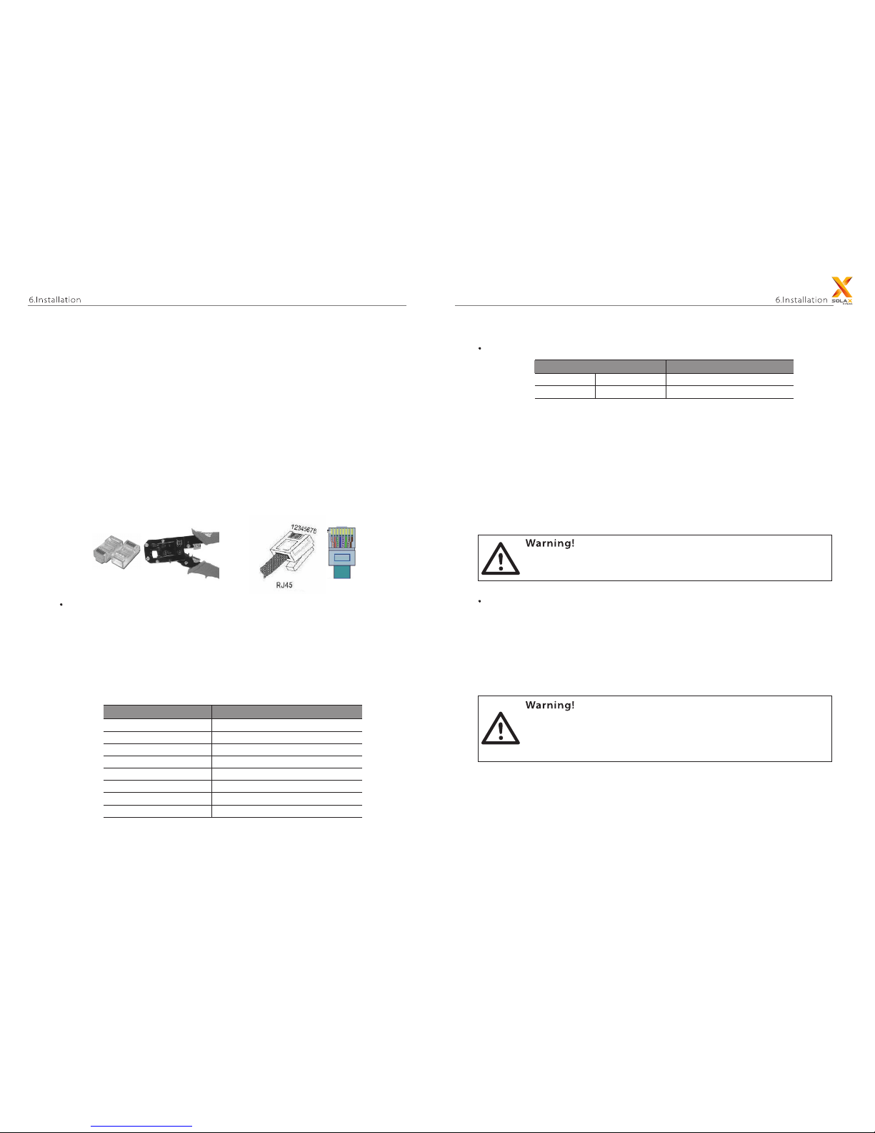
The correspond relationship of the pins of RJ 45 and network cable color shows
as below.
Choose high-quality network cable, trip the insulation from the wire ends. For the
end use for the inverter, follow T568B order with press pliers to push into the 8wire RJ 45 crystal head. For the other end, follow the 2-wire RJ 45 crystal head to
connect with the RS 485 converter connector.
User can update the system through a USB flash drive.
RS 485 converter connection
Communication
Connection steps
6.5 .2 Communica tion In terface
RS 485 Communication
USB for Updating
RJ 45 Line NO.
Cable Color
T568B connection order
1
4
2
5
3
4
5
6
7
8
Cable Color
RS 485 Converter
Whight orange
A
B
Orange
White green
Blue
Blue
White blue
White blue
Green
White brown
Brown
3. Connect the WiFi with the router. ( Please refer to “WiFi Setting Guide”.)
4. Set the station account on the Solax web. (Please refer to “WiFi Setting Guide”.)
Connection steps
b) Make sure the DC switch is off and disconnect the AC with grid. Insert USB flash
drive into the “USB” port on the bottom of X1. Then turn on DC switch or connect
the PV connector, green light “a” and red light “b” flash alternately for 10 times.
Indicator light “c”, “d”, “e”, “f” are unlit.
a) Prepare a USB flash drive. Download the latest installation package named
“update.rar” from Solax website: www.solaxpower.com. And then extract it into
following directory:
“update\ARM\618.000 _X1MINI_ARM_Vx.xx_xxxxxxxx.usb”;72.00
“update\DSP\618.000 _X1MINI_DSP_Vx.xx_xxxxxxxx.hex”.70.00
Make sure the input voltage is more than 100V (in good illumination
condition). Or it may result in failing during updating.
Make sure the d irect or y is in accorda nc e wi th above form s tr ic tly!
Do not mo di fy t he progra m fi le name and the c apita l lette r ca n no t
be ch anged t o lo wer case! Or it m ay c ause the inve rter d oe sn’ t
wor k anymo re !
22
23

DRM: demand response mode.
DRM is provided to give a remote control with the optional accessory. The
remote control function provides a contact signal to operate the inverter. The
pin definition and the circuit connection show as below.
1. Choose at least 1mm² wire. Trip the insulation from the wire ends.
2. Insert the tripped wire into the hole of the terminal block.
3. Screw down the screws on the terminal block.
DRM
E.F.Alarm (optional)
Communication
Connection steps
1
8
Pin
Definition
1 2 3 4 5 6 7 8
DRM1 DRM2 DRM3 DRM4 3.3V DRM0 GND G ND
3. About 10 seconds later, the system will be updated automatically. During this
period, green light “a” is always been on and red light “b” is unlit. Indicator light “c”,
”d”, “e”, “f” show the progress of system updating. Refer to figure , it represents Ⅱ
the updating is half-finished.
4. Once system updating has been finished completely, light “a” “c” “d” “e” “f ” are all
being on, as shown in figure . Ⅲ
b
c
f
d
e
a
(Ⅰ ) (Ⅱ )
(Ⅲ )
24
25
E.F.Alarm means Earth Fault Alarm. It is the additional detection for functionally
earthed PV arrays, as required by AS 4777.2 and AS/NZS 5033.
a) Measure the resistance to earth of each conductor of the PV array.
b) If the earth resistance is above the resistance limit(R limit) threshold 30KΩ , the
iso
system shall reconnect the functional earth and shall be allowed to start.
c) If the earth resistance is equal to or less than the resistance limit(R limit) threshold
iso
30KΩ , the inverter shall shut down and initiate an earth fault alarm in accordance with
the requirements of IEC 62109-2.
Dir ec t fu nc ti onal ear th ing of syst em i s no t recomme nd ed.
Function al e ar thing via a r es is itor is a saf er option .
Not e !
Dur ing updatin g, d on’ t switch of f th e DC switch or c ut o ff t he
external dc b re ak er !
If the updati ng p rocess is pau se d for more th an 3 m inutes,
ple ase rei ns er t the US B flash drive.
Not e !
The updating process for ARM needs about 5 seconds and DSP needs about 3
minutes.

Checking: Inverter will check output environment automatically when DC
output voltage of PV panels. Under this mode, the green light “a” is ickering,
shown as gure . Ⅲ
Normal: begins to operate normally with green light on. Inverters will Inverter
work in MPPT mode when P V voltage is in the MPPT voltage range, inverter
will stop feedback power to grid when PV power is not enough.
Under this mode, the green light “a” is always on, light “b, c, d, e” represent the
output power. As shown in gure , the output power is 0%~25%.Ⅳ
If indicator light “b” turns red (Fault status), please refer to page
26-27.
60Vgreater
100V
Under this mode, the green light “a” is ickering,
shown as gure .Ⅱ
ed.
V
(Ⅰ ) (Ⅱ )
(Ⅲ ) (Ⅳ)
b
c
f
d
e
a
indicator lamps that identify the inverter output
power range and type of fault.
I
operating
Fault(red) Normal(green)
26
27

Waiting/Checking
Updating
Indicator light “a“ is always being on. And
indicator light “c” ,“d” , “e” ,“f” represent the
output power refer to Table-part 2. As
shown left, it represents the output power
is 25% ~ 50%.
Indicator light “b“ is always being on. And
indicator light “c” ,“d” , “e” ,“f” represent the
type of error refer to Table -part 2.
Under this mode, indicator light “a” is
ickering. Other lights are unlit.
Please refer to page 21.
First, read all indicator lamps, if the state of lamps “a” to “f” is ” bright, unlit, bright,
bright, unlit, unlit”, the corresponding gures is ” ” . Refer to Table-Part2,
it can be concluded that the operating state
of inverter is normal.
Then, read the power/fault indicator state, if the state of lamps “a” to “f ” is ‘’unlit,
bright, bright, unlit, unlit, unlit, unlit”, the corresponding gures is “ ”
It could be nd that the type of error is “PV Over Voltage Fault”
refer to Table-Part 3.
Description
b
c
f
d
e
a
Indicator Light
a, b
c, d, e, f
Indicate normal / error
Indicate output power or the type of error
Explanation
28
29
PV Volt Fault
PV Over Voltage Fault
Isolation FaultIsolation Fault
Temp Over FaultOver Temperature Fault
DCI Device Fault
DCI OCP Fault
DCI Fault
RCD Fault
Grid Lost Fault
Mains Lost
RCD /RC Fault
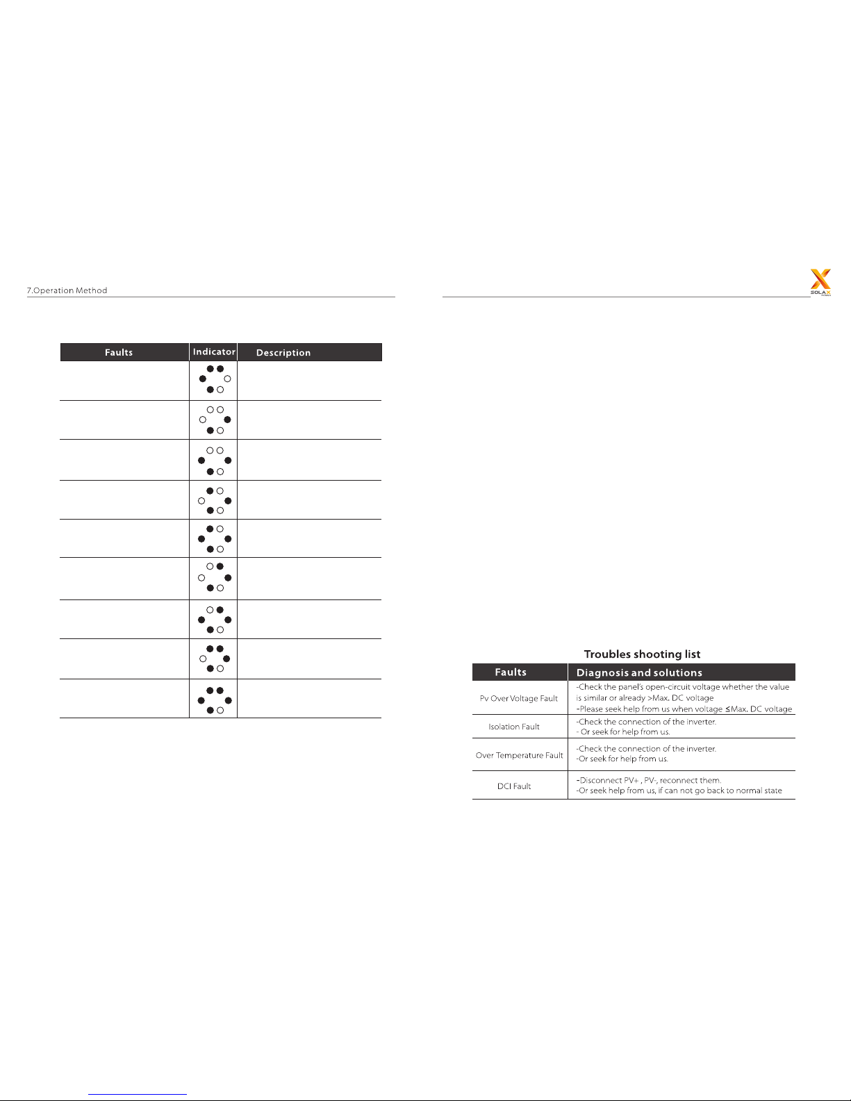
Sample Fault
Consistant Fault
Relay FaultRelay Fault
Inv Eeprom Error
Eeprom Fault
Mgr Eeprom Fault
Include SPI,SCI Faults
Comms Lost
Bus Volt Fault
Bus High
Tz Protect Fault
Tz Fault
SW OCP Fault
Other Device Fault
Other Device Fault
PLL Lost Fault
Grid Volt FaultGrid Volt Fault
Grid Freq FaultGrid Freq Fault
30
31
8. Troubleshooting
8.1 Troubleshooting
This section contains information and procedures for solving possible problems
with the X1 series inverter, and provides some troubleshooting tips to identify
and solve most problems that could occur with X1 series inverter.
This section will help you narrow down the source of any problems you may
encounter. Please read the following troubleshooting steps.
Check the indicator light state. Record it before anything further solutions.
Attempt the solution indicated in troubles shooting list.
If the indicator lamp unlit, check the following list to make sure that the present
state of the installation allows proper operation.
- Is the inverter located in a clean, dry, adequately ventilated place?
- Have the DC input breakers been opened?
- Are the cables adequately sized and short enough?
- Are the communication cable properly connected and undamaged?
Please contact SolaX Power company customer service for further assistance.
Please be prepared to describe details of your system installation and provide
the model and serial number of the unit.
8. Troubleshooting

8. Troubleshooting
Tz Fault
RCD /RC Fault
32
33
9. Decommissioning
2.
3.
8.2 Routine Manitenance

9. Decommissioning
9.1 Decommissioning
9.2 Storage and Transportation
9.3 Disposal
8. Troubleshooting
~
34
 Loading...