


Triple Power Lithium-ion Battery
User Manual
50Ah
SolaX Power Network Technology (Zhejiang) Co., Ltd.
Add.: No. 288, Shizhu Road, Tonglu Economic Development Zone, Tonglu City,
Zhejiang Province, 310000 P.R. CHINA
Tel.: +86 (0) 571-56260011
E-mail: info@solaxpower.com
320101004909
Copyright © SolaX Power Technology (Zhejiang) Co., Ltd. All rights reserved.
No part of this document may be reproduced or transmitted in any form or by any means without
prior written consent of SolaX Power Technology (Zhejiang) Co., Ltd. (hereinafter referred to as
SolaX). SolaX reserves the right of final interpretation.

CHANGE HISTORY
Changes between document versions are cumulative. The latest version contains
all updates made in previous versions.
Version 10 (Dec. 16, 2022)
Added info on T-BAT H 5.8 V2
Version 09 (Nov. 23, 2022)
Modied IP rate, certication icon
Added a "Note"
Version 08 (Sep. 9, 2022)
Modied TUV ICON
Modied CAN into BMS
Version 07 (Jun. 8, 2022)
Added ukca icon, and waterproof cap in the gures
Added a method of oor mounting
Version 06 (May 18, 2021)
Added a supplementary note about battery SOC
Version 05 (May 11, 2021)
Added Chapter 8
Version 02 (Nov. 7, 2019)
Change appearance drawing
Added Ground Nut
Delete the black surface of the s1 and s2 indicator lights
Version 01 (Jun. 4, 2019)
Delete one terminal on both the positive and negative power cables)
Version 00 (Apr. 26, 2019)
Initial release

Contents
CONTENTS
1 NOTE ON THIS MANUAL
1.1 SCOPE OF VALIDITY.......................................................................................... 1
1.2 TARGET GROUP................................................................................................... 1
1.3 SYMBOLS USED................................................................................................... 1
2 SAFETY
2.1 SAFETY INSTRUCTIONS................................................................................. 2
2.1.1 GENERAL SAFETY PRECAUTIONS............................................................. 2
2.1.2 EXPLANATION OF SYMBOLS........................................................................3
2.2 RESPONSE TO EMERGENCY SITUATIONS.........................................5
2.2.1 LEAKING BATTERIES.............................................................................................5
2.2.2 FIRE....................................................................................................................................5
2.2.3 WET BATTERIES AND DAMAGED BATTERIES....................................5
2.3 QUALIFIED INSTALLER.....................................................................................6
3 PRODUCT INTRODUCTION
3.1 PRODUCT OVERVIEW......................................................................................7
3.1.1 DIMENSION AND WEIGHT..............................................................................7
3.1.2 APPEARANCE............................................................................................................8
3.2 BASIC FEATURES.................................................................................................
3.2.1 FEATURES....................................................................................................................
3.2.2 CERTIFICATIONS....................................................................................................
3.3 SPECIFICATIONS.................................................................................................11
3.3.1 T-BAT SYS-HV CONFIGURATION LIST.................................................... 11
3.3.2 PERFORMANCE....................................................................................................11
4 INSTALLATION
4.1 INSTALLATION PREREQUISITES...............................................................12
4.2 SAFETY GEAR.......................................................................................................
4.3 TOOLS........................................................................................................................ 13
4.4 INSTALLATION..................................................................................................... 13
4.4.1 CHECK FOR TRANSPORT DAMAGE.................................................... 13
4.4.2 UNPACKING............................................................................................................. 13
4.4.3 ACCESSORIES......................................................................................................... 14
4.4.4 ................................................... 16
...................................................................................................................................
...............................................................................................................
BATTERY INSTALLATION STEPS
..........................................................................................
.................................................................................
...........
10
10
10
12
12
Contents
4.5 CABLE CONNECTION.........................................................................................................
4.5.1 .................CONNECTING POWER CABLES BET WEEN BATTERY PACKS
4.5.2 ....................................................CONNECTING POWER CABLES TO INVERTER
1
2
7
4.5.3 CONNECTING BMS COMMUNICATION CABLE................................................
4.5.4 ............................................CONNECTING RS485 COMMUNICATION CABLE
4.5.5 .......................................................................................CONNECTING GROUND WIRE
4.5.6 .....................................................................................................OVERALL INSTALLATION
4.6 OVERVIEW OF INSTALLATION......................................................................................
5 COMMISSIONING...................................................................................................................................
5.1 CONFIGURING BATTERY SYSTEM.............................................................................
5.2 COMMISSIONING..................................................................................................................
5.3 STATUS INDICATORS...........................................................................................................
5.3.1 BMS ....................................................................................................................................................
5.3.2 BATTERY .............................................................................................................................PACK
5.4 SHUTTING DOWN T-BAT SYSTEM............................................................................
6 TROUBLESHOOTING..........................................................................................................................
6.1 TROUBLESHOOTING...........................................................................................................
7 DECOMMISSIONING...........................................................................................................................
7.1 DISMANTLING THE BATTERY.........................................................................................
7.2 PACKAGING................................................................................................................................
8 MAINTENANCE ........................................................................................................................................
9
*
DISCLAIMER................................................................................................................................................
WARRANTY REGISTRATION FORM
20
20
22
26
27
28
29
31
32
32
33
35
35
36
36
37
37
40
40
40
41
42

1 Note on this Manual
1.1 Scope of Validity
This manual is an integral part of T-BAT Series. It describes the assembly,
installation, commissioning, maintenance and failure of the product. Please read
it carefully before operating.
T-BAT SYS-HV
T-BAT H 5.8 V2
T-BAT PACK-HV
Hv11550 V2
NOTE: There are 4 models for T-BAT system, including BMS and battery packs.
Please refer to section 3.3.1 T-BAT SYS HV Conguration Liston page 11 for more
information.
1.2 Target Group
This manual is for qualifed electricians. The tasks described in this manual may
only be performed by qualifed electricians.
1.3 Symbols Used
DANGER!
“DANGER” indicates a hazardous situation which, if not avoided,
will result in death or serious injury.
WARNING!
“WARNING” indicates a hazardous situation which, if not avoided,
could result in death or serious injury.
CAUTIOIN!
“CAUTION” indicates a hazardous situation which, if not avoided,
could result in minor or moderate injury.
NOTE!
“NOTE” provides tips that are valuable for the optimal operation
of your product.
123

2 Safety
2.1 Safety Instructions
For safety reasons, installers are responsible for familiarizing themselves with the
contents of this manual and all warnings before performing installation.
2.1.1 General Safety Precautions
WARNING!
Please don't crush or impact the battery, and always dispose it
according to the safety regulation.
Observe the following precautions:
Risks of explosion
·
– Do not subject the battery to strong impacts.
– Do not crush or puncture the battery.
– Do not dispose of the battery in a re.
· Risks of re
– Do not expose the battery to temperatures in excess of 55°C.
– Do not place the battery near a heat source, such as a replace.
– Do not expose the battery to direct sunlight.
– Do not allow the battery connectors to touch conductive objects such as
wires.
· Risks of electric shock
– Do not disassemble the battery.
– Do not touch the battery with wet hands.
– Do not expose the battery to moisture or liquids.
– Keep the battery away from children and animals.
· Risks of damage to the battery
– Do not allow the battery to get in contact with liquids.
– Do not subject the battery to high pressures.
– Do not place any objects on top of the battery.
2.1.2 Explanation of Symbols
This section gives an explanation of all the symbols shown on the T-BAT system
and on the warning label.
Lable
CAUTION!
If the battery is not installed within one month after receiving the battery,
the battery must be charged till the SOC is more than 50% for maintains.
Symbol Explanation
Symbol Explanation
The inverter complies with the requirements of the applicable
CE guidelines
T-BAT SYS-HV can only be used in the household energy eld. It is not allowed to
be used in other industries, such as the medical equipment industry and
automotive application industry.
Symbol
272687
The inverter complies with the requirements of the applicable
UKCA guidelines
The inverter complies with the requirements of the applicable
Explanation
CSA guidelines

The battery system should not be disposed together with the
household waste.
Disposal information can be found in the enclosed documentation.
TUV mark for IEC62619
The battery system should be disposed of at a proper facility
for environmentally safe recycling.
The battery system should not be disposed together with the
household waste.
Disposal information can be found in the enclosed documentation.
Wear protecitve glasses
2.2 Response to Emergency Situations
2.2.1 Leaking Batteries
If the battery leaks electrolyte which is corrosive, avoid contact with the leaking
liquid or gas. Direct contact may lead to skin irritation or chemical burns. If one
is exposed to the leaked substance, do these actions:
Accidental inhalation of harmful substances:Evacuate people from the
contaminated area, and seek medical attention immediately.
Eye contact: Rinse eyes with fowing water for 15 minutes, and seek medical
attention immediately.
Dermal contact: Wash the affected area thoroughly with soap and water, and
seek medical attention immediately.
Ingestion: Induce vomiting, and seek medical attention immediately.
2.2.2 Fire
Please keep a Class ABC re extinguisher or a carbon dioxide extinguisher
near the equipment.
WARNING!
The battery pack may catch re when heated above 150°C.
Observe enclosed documentation.
If a re beaks out at where the battery is installed, do these
actions:
1. Extinguish the re beore the batterry catches re;
Keep the battery system away from open fames or ignition
sources.
2. If the battery has caught re, do not try to extinguish the
re. Evacuate people immediately.
WARNING!
If the battery catches re, it will produce noxious and poisonous gases. Do
Keep the battery system away from children.
not approach.
2.2.3 Wet Batteries and Damaged Batteries
Danger of high voltages.
Danger to life due to high voltages in the battery system!
If the battery is wet or submerged in water, do not try to access it.
If the battery seems to be damaged, they are not t or use and may pose a
danger to people or property.
Please pack the battery in its original container, and then return it to our
Danger.
company or your distributor.
Risk of electric shock!
CAUTION!
The battery pack may explode.
Damaged batteries may leak electrolyte or produce ammable gas. If you
suspect such damage, immediately contact our company for advice and
support.
4
5

3. Product Introduction
2.3 Qualied Installer
WARNING!
All operations of T-BAT SYS-HV relating to electrical connection and
installation must be carried out by qualied personnel.
A skilled worker is dened as a trained and qualied electrician or installer who
has all of the following skills and experience:
Ÿ Knowledge of the functional principles and operation of on-grid systems;
Ÿ Knowledge of dangers and risks associated with installing and using
electrical devices and acceptable mitigation methods;
Ÿ Knowledge of the installation of electrical devices;
Ÿ Knowledge of and adherence to this Manual and all safety precautions and
best practices;
3 Product Introduction
Since the battery is upgraded to the second generation, there are some
differences between the rst and second generations, such as battery cell, chip,
and appearance.
3.1 Product Overview
3.1.1 Demension and Weight
A battery management system (BMS) is an electronic system that manages a
rechargeable battery.
Battery is a type of electrical battery which can be charged, discharged into a
load.
A battery system includes a BMS and battery pack(s) .
HV11550 V2
474mm
193mm
647mm
68.5kg
Length
Width
Height
Weight
T-BAT H 5.8 V2
474mm
193mm
708mm
72.2kg
47
4
T-BAT H 5.8 V2
708
47
93
1
4
19
HV11550 V2
647
3
(Battery Pack)
6
7

3. Product Introduction
3. Product Introduction
3.1.2 Appearance
Section view of T-BAT H 5.8 V2
Ÿ
Ⅰ
BAT+BAT-
Ⅳ
BMS
Ⅱ Ⅲ
Ⅸ
Ⅷ
Object Mark
BAT+/BAT-
BMS
GND
YPLUG
RS485 II
POWER
DIP
ON/OFF
Section view of HV11550 V2
Ÿ
Ⅴ Ⅵ
YPLUG
-
RS485 II
Ⅶ
Ⅲ
Ⅹ
Description
Charge/Discharge Connectors
BMS Connector
GND
/
-
Power Connector to + of next battery pack, or to
Power Connector’ to XPLUG of next battery pack,
Air Valve
YPLUG of the same pack
or to “-” of the same pack
Ⅰ’
XPLUG
RS485 I
Ⅲ’
Ⅱ’
+
Ⅴ’
Ⅳ’
Object
II’
III’
IV’
V’
VI’
VII’
VIII’
Mark
I’
XPLUG
+
RS485 I
GND
/
-
YPLUG
RS485 II
Power Connector’ to YPLUG of upper battery pack
Power Connector to “-” of upper battery pack
RS485 Connector to RS485 II of upper battery pack
GND
Air valve
Power Connector to + of next battery pack, or to
YPLUG of the same pack
Power Connector’ to XPLUG of next battery pack,
or to “-” of the same pack
Rs485 Connector to RS485 I of next battery pack
Description
Ⅵ’
Ⅶ’
YPLUG
-
RS485 II
Ⅷ’Ⅳ’
RS485 Connector to RS485 I of next battery pack
Power Button
DIP Switch
Circuit Breaker
8
9

3. Product Introduction
3. Product Introduction
3.2 Basic Features
3.2.1 Features
The T-BAT SYS-HV is one of the advanced energy storage systems on the market
today, incorporating state-of-the-art technology, high reliability, and convenient
control features shown as below:
Ÿ 90% DOD
Ÿ 99% faradic charge efficiency
Ÿ 95% battery roundtrip efficiency
Ÿ Cycle life > 6000 times
Ÿ Secondary protection by hardware
Ÿ IP65 protection level
Ÿ Safety & reliability
Ÿ Small footprint
Ÿ Floor or wall mounting
3.2.2 Certications
T-BAT system safety
Battery cell safety
UN number
Hazardous materials classication
UN transportation testing requirements
International protection marking
CE, FCC, RCM, TUV (IEC 62619),
UL1973,ROHS
UL 1642
UN 3480
Class 9
UN 38.3
IP65
3.3 Specications
3.3.1 T-BAT SYS-HV Conguration List
No.
1 5.8 100-131
2
3 17.3
4 23.0 400-524
Model
T-BAT H 5.8 V2
T-BAT H 11.5 V2
T-BAT H 17.3 V2
T-BAT H 23.0 V2
T-BAT H 5.8 V2*1+HV11550 V2*1
T-BAT H 5.8 V2*1+HV11550 V2*2
T-BAT H 5.8 V2*1+HV11550 V2*3
3.3.2 Performance
Dimension(mm)
Weight(kg)
Nominal Voltage(Vdc)
Operating Voltage(Vdc):
Nominal Capacity(Ah):
Max. charge/discharge Current(A) :
Recommend Charge/Discharge Current (A):
Standard Power(kW)
Maximum Power(kW)
Altitude(m)
Faradic Charge Efficiency( )25°C/77°F
Battery Roundtrip Efficiency( /3, )C 25°C/77°F
Expected Lifetime( )25°C/77°F
Cycle life(90% DOD, )25°C/77°F
Available Operating Temperature
Optimal Operating Temperature
Storage Temperature
Ingress Protection
Battery Pack Energy(kWh)
T-BAT H 5.8 V2*1
11.5
T-BAT H 5.8 V2
474* 193*708
72.2
115.2
100-131
50
35
25
2.5
3.5
≤ 2000
99%
95%
10 years
6000 cycles
0-55°C
15-35°C
-20-5 (3 months)5°C
0- 0 (1 year)4 °C
IP65
Voltage (V )
200-262
300-393
HV11550 V2
474*193*647
68.5
115.2
100-131
50
35
25
2.5
3.5
10
11

4. Installation
4. Installation
4 Installation
4.1 Installation Prerequisites
Before installation, make sure that the installation site meets the following
conditions:
• The building is designed with resistance to earthquakes;
• The location is far away from the sea, to avoid sea water and humid air;
• The oor shall be at;
• There are no ammable or explosive materials nearby;
• The ambiance shall be shady and cool, away from heat sources and direct
sunlight;
• The temperature and humidity remain at a constant level;
• The installation site requires less dust and dirt;
• There are no corrosive gases, including ammonia and acid vapor; and
• The same generation products are recommended to give priority to use.
NOTE!
The Triple Power battery is rated at IP65. Thus, it can be installed outdoors as
well as indoors. However, if the battery is installed outdoors, avoid direct
exposure to the sun and humid air.
NOTE!
If the ambient temperature is beyond the operating range, the battery will
stop operating to protect itself. The optimal temperature range for the
battery to operate is from 15°C to 35°C. Frequent exposure to harsh
temperatures may deteriorate the performance and lifetime of the battery.
NOTE!
When installing the battery for the rst time, the manufacturing date
between battery modules should not exceed 3 months.
4.2 Safety Gear
Installation and maintenance personnel must operate according to
applicable federal, state and local regulations as well as the industry standard.
The product installation personnel shall wear safety gears, etc. in order to
avoid short circuit and personal injury.
4.3 Tools
These tools are required to install the T-BAT system.
Torque Screwdriver Phillips Screwdriver
Phillips Screwdriver Slotted Screwdriver Torque Wrench
Tape Measure
Driller
Hexagon Wrench
Pencil or Marker
4.4 Installation
4.4.1 Check for Transport Damage
Make sure the battery is intact during transportation. If there are any visible
damages, such as cracks, please contact your dealer immediately.
4.4.2 Unpacking
Unpack the battery package by removing the packing tape. Ensure the battery
modules and relevant items are complete. See the package items on section
4.4.3 and check the packing list carefully. If any items are missing, immediately
contact our company or your distributor.
CAUTION!
According to regional regulations, several people may be required for
moving the equipment.
WARNING!
Please strictly follow the installation steps. The company will not assume
any responsibility for any hurting or loss caused by improper
assembling and operation.
12
Insulated Gloves Safety Goggles Safety Shoes
13

4. Installation
4. Installation
4.4.3 Accessories
T-BAT H 5.8 V2:
A*
D
H
I
B* C
E
F
J
K L
G
M
The table below lists the number of each component.
Object
Description
A*
Power cable between inverter and T-BAT H 5.8 V2 (+) (2 m)
B*
Power cable between inverter and T-BAT H 5.8 V2 (-) (2 m)
C
BMS communication cable (2m)
D
Series-connected plug
E
Cover plate1
F
M4 screw
G
Cover plate2
H
Wall bracket
I
M5 screw
J
Expansion bolt
K
Ring terminal (for grounding)
L
Power cable disassembling tool
Documents
M
Quantity
1
1
1
1
2
8
2
1
1
5
2
1
2
Note:
1. The above-mentioned accessories are only for one battery module. SolaX will
provide corresponding accessories according to the number of battery
modules.
2. The mark “*” indicates that the connector connecting to inverter on the charging
cable, connecting battery and inverter, is delivered with the inverter's kit.
HV11550 V2:
A1
D1 E1
I1
B1
J1
K1
The table below lists the number of each component.
Description
A1
Power cable between battery packs (650mm)
B1
Power cable’ between battery packs (650mm)
C1
RS485 communication cable (650mm)
D1
Cover plate1
E1
M4 screw
F1
Cover plate2
G1
Wall bracket
H1
M5 screw
I1
Expansion bolt
Ring terminal (for grounding)
J1
Document
K1
C1
G1 H1F1
Quantity Object
1
1
1
2
8
2
1
1
5
2
1
14
15

4. Installation
4.4.4 Battery Installation Steps
There are two installation ways, wall mounting and oor mounting.
I. Wall mounting
It is recommended to keep a distance of 350 mm between two battery packs.
Such a distance must be between 320 mm and 380 mm.
Steps (for T-BAT H 5.8 V2 or HV11550 V2):
Make sure the wall is strong enough to withstand the weight of battery.
Step 1: Fix the wall brakcet (H or G1) on the wall
• Use the wall bracket as a template to mark the position of the 5 holes;
• Drill holes with φ10 driller, make sure the holes are deep enough (at least
50mm) for installing and tightening the expansion bolts (J or I1);
• Install the expansion bolts in the wall, and tighten the screws on the bracket by
using the screw driller.
4. Installation
30<height<300(mm)
Step 2: Match the battery with the wall bracket
• Lift the battery to the wall bracket;
• Hang the battery over the wall bracket, move the battery close to the wall and
match it on the wall bracket.
Step3: Lock the joint between hanging board and wall bracket with M5
combinationscrew (I or H1).
Note: Keep the distance from installation point to the oor less than 650mm.
380<height<650mm
16
Side view of hanging the battery on
the wall bracket.
17

4. Installation
II. Floor mounting
Steps (for T-BAT H 5.8 V2 or HV11550 V2), please refer to the steps for wall
mounting on page 16.
Note: It is recommended to keep a distance of 350 mm between two battery
packs. Such a distance must be between 320 mm and 380 mm.
① ②
Height<350mm
③ ④
Side view of hanging
the battery on the
wall bracket.
4. Installation
Wall bracket
235 mm< height < 240 mm
18
Note: To prevent the battery from
becoming moist, it is recommended to
place a foam cushion, or other cushion
made up of other materials, with a height of
3 cm to 4 cm, under the battery.
19
4. Installation
4. Installation
4.5 Cable Connection
4.5.1 Connecting Power Cables between Battery Packs
For V2:T-BAT H 5.8
1. The only step of connecting power cable for V2 is T-BAT H 5.8
connecting the series-connected cable to “-” and “YPLUG” on the right side.
The series-connected cable is used to make a complete circuit.
YPLUG
YPLUG
-
RS485 II
-
RS485 II
For T-BAT H 5.8 V2 + 1~3 battery packs:
1. Connect “-” ( for T-BAT H 5.8 or for ) V V2 VI’ HV11550 V2
o II’n the right side to “+” ( ) on the left side of the next battery pack.
2. Connect “YPLUG” ( for T-BAT H 5.8 or for ) VI V2 VII’ HV11550 V2
On the right side to “XPLUG” ( ) on the left side of the next battery pack.I
3. The rest battery packs are connected in the same way.
4. Insert the series-connected cable at “-” and “YPLUG” on the right side of last
battery pack to make a complete circuit.
XPLUG
RS485
+
YPLUG
-
YPLUG
-
YPLUG
-
RS485 II
20
RS485 II
YPLUG
-
RS485 II
RS485 II
Note!
Regardless of how many battery modules the user install, please put a
waterproof cap on the unconnected communication port of the battery
module.
21

4. Installation
4. Installation
4.5.2 Connecting Power Cables to Inverter
This step is going to connect power cables between inverter and T-BAT system.
The default length of power cables are 2 meters, so customers can appropriately
cut the cable according to the actual installation environment. As a result, each
Power cable has one terminal block when leaving the factory, and customers
need to connect the other end of terminal block by themselves.
Battery Breaker:
Ø
To ensure the safety of users, a non-polar DC MCB must be installed before
connecting inverter.
The battery needs to be securely disconnect before maintenance.
Inverter-and-battery Connection Diagram
Ø
Non-polar
DC MCB
Power line connection
- +
Communication line connection
CAN/RS485
Cable Connection Steps:
Ø
Step1. Strip the cable to 15mm.
Step2. Insert the stripped cable up to the stop (negative cable for DC plug(-) and
positive cable for DC socket(+) are live). Hold the housing on the screw
connection.
Step3. Press down the spring clamp until it clicks audibly into place (You should be
able to see the ne wie strands in the chamber)
Step4. Tighten the screw connection(tightening torque:2.0±0.2Nm)
Step2.
screw connection
DC plug housing(-)
Step3. Step 4.
chamber
spring
wire strands
screw connection
DC socket housing(+)
22
... ...
High voltage lithium battery
23

4. Installation
4. Installation
Connecting Charging Cables between Inverter and T-BAT System:
Ø
1. Connect the the positive cable (+) (A) and negative cable (-) (B) to the
BAT+ and BAT- respectively as shown in the following gure.
BAT- BAT+
-
+
BMS
BAT- BAT+
BMS
2. Keep the inverter off. Connect the other end of power cables (+,-) to the BAT
(+,-) port on the inverter.
Disassembling Power cable (on BAT+, BAT-, “+”, XPLUG port)
Ø
Disassemble the power cable by plugging the slot type screwdriver or the Power
cable disassemble tool(L) to the terminal groove of the power cable. Please see
the illustration as shown below:
BAT- BAT+
BMS
BAT- BAT+
-
+
BMS
BAT- BAT+
BMS
WiFi
+
BAT
DRM
-
AC
Meter
RF
485
BMS
Upgrade
NOTE!
1. When connecting the cable to inverter, t the two connectors together until
the connection audibly locks into place.
2. Check to make sure the connection is securely locked.
3. Don't shake both ends of the cable at the joint once the connection is locked.
22
CAUTION!
DO NOT disassemble power cables when the T-BAT system is not
turned off, otherwise there would be an arc discharge that could
cause serious injury!
23

4. Installation
4. Installation
Ø
Disassembling Power Cable (on ”-”, YPLUG port)
Disassemble the power line by plugging the Power cable disassembling tool(L)
to the terminal groove of charging cable. Please see the illustration as shown
below:
YPLUG
-
YPLUG
-
RS485 II
RS485 II
4.5.3 Connecting BMS Communication Cable
It is required for the BMS to communicate with the inverter for proper operation.
1. Insert one end of the BMS communication
Cable (C) directly to the BMS port of inverter.
2. Insert the other end of the BMS communication
BAT- BAT+
Cable to the BMS connector ( )on the rst battey II
which is marked in red.
Assemble the cable gland and tighten the cable
BMS
cap.
24
YPLUG
-
The wiring order of the communication cable is as follow:
RS485 II
5
3
6 7 8
4
1 2
1) Orange stripes on white
2) Orange
3) Green stripes on white
4) Blue
5) Blue stripes on white
6) Green
7) Brown stripes on white
8) Brown
Sequence
BMS
1 2 3 4 5 6 7 8
/
GND
/
BMS_H
BMS_L
/
A1
B1
25

4. Installation
4. Installation
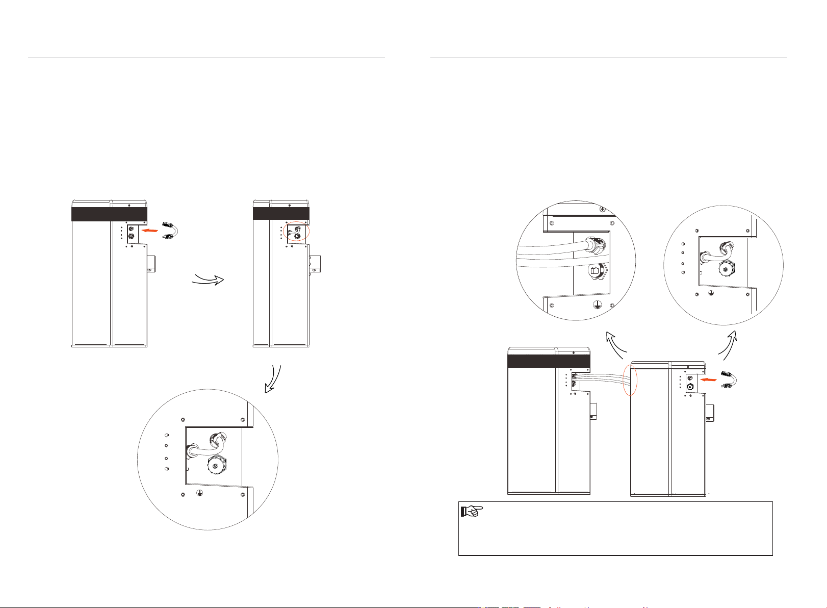
4.5.4 Connecting RS485 Communication Cable
For T-BAT H 5.8 V2:
There's no need to use RS485 communicaton cable.
For T-BAT H 5.8 V2 + 1~3 battery packs:
Connect RS485 II ( for T-BAT H 5.8 or for ) VII V2 VIII’ HV11550 V2
of the rst battey pack (as shown on the right) to RS485 I on the next battery pack
(as shown on the left). Assemble the cable gland and tighten the cable cap.
XPLUG
+
RS485 I
YPLUG
-
RS485 II
YPLUG
-
RS485 II
YPLUG
-
RS485 II
4.5.5 Connecting Ground Wire
The terminal point for GND connection is on the side of grooves as shown
below:
Cable size: 10AWG.
Ring terminal
YPLUG
-
YPLUG
RS485 II
-
The wiring order of the communication cable is as follow:
Sequence 1 2
RS485I
RS485II
VCC_485
VCC_485
GND_485
GND_485
B2
B2
3
4 5
NN-
26
P+
P+
A2
A2
6
7 8
VCC_485_2
VCC_485_2
GND_485
GND_485
RS485 II
CAUTION!
GND connection is mandatory!
27

4. Installation
4. Installation
4.5.6 Overall Installation
It is recommended to protect the cables with corrugated pipe.
For T-BAT H 5.8 V2:
1. Connect all the cables on the left side of T-BAT H 5.8 V2.
2. Run the cables through the corrugated pipe.
3. Do remember to insert the series-connected cable at “-” and “YPLUG” on the
right side of the last battery pack to complete the internal circuit.
4. Set the cables into the groove of metal plates and screw them back to the
battery pack on both sides.
For T-BAT H 5.8 V2 + 1~3 battery packs:
1. Connect the cables at one end of the T-BAT H 5.8 V2 /HV11550 V2.
2. Run the cables through the corrugated pipe.
3. Set the cables into the groove of metal plates and screw them back to the
battery packs on both sides.
4. Do remember to insert the series-connected cable at “-” and “YPLUG” on the
right side of the last battery pack to complete the internal circuit.
28
29

4. Installation
4.6 Overview of Installation
The following diagram is a completed T-BAT system installation with T-BAT H 5.8 V2
+ three battery packs.
4. Installation
30
CAUTION!
One T-BAT system is allowed to install one T-BAT H 5.8 V2
with three battery packs at most. Connecting more than three battery
packs to the T-BAT system will blow the fuse, and the batteries will be
damaged. Please keep in mind and follow this instruction.
31

5. Commissioning
5. Commissioning
5 Commissioning
5.1 Conguing Batery System
The DIP switch is used to congue the number of battey packs which are
communicating to inverter. The detailed conguration inomation is shown as
follows:
6
5
4
3
Conguration a tivated by inverters
0- Matching T-BAT H 5.8 V2 (default)
1- Matching T-BAT H 5.8 V2 + 1*HV11550 V2
2- Matching T-BAT H 5.8 V2 + 2*HV11550 V2
3- Matching T-BAT H 5.8 V2 + 3*HV11550 V2
Black-start conguration
Ø
The black-start function is only used in the off-grid environment when there is no
other power supply.
Note: if the battery is started in black-start mode, although there is no BMS
communication, the port still has high voltage and there is a risk of electric
shock!
7
0
1
2
5.2 Commissioning
NOTE!
When powering on the BMS, the system will start self-testing. If the
buzzer bips, it means DIP conguration fault or communication failue
occurs. If the buzzer bips, please check if the number of battery packs is
corresponding to the DIP conguration, and also check if the RS485
communication cables are correctly connected. After checking above
two situations, press the POWER button to power on, and press the
POWER button again 10s later. In addition: The buzzer will only alarm on
the corresponding fault during the power-on self-test. When the selftest is completed, it won't bip again even if the same fault occurs.
NOTE!
Frequently pressing the POWER button may cause system error. Please
make sure at least 10 seconds is left before you pressing the POWER
button the second time.
After the black-start mode is started, if the BMS communication couldn't be built
within 3 minutes , the black-start fails.
4- Matching T-BAT H 5.8 V2
5- Matching T-BAT H 5.8 V2 + 1*HV11550 V2
6- Matching T-BAT H 5.8 V2 + 2*HV11550 V2
7- Matching T-BAT H 5.8 V2 + 3*HV11550 V2
32
33

5. Commissioning
5. Commissioning
Commissioning Steps
If all the battery packs are installed, follow these steps to put it in operation.
1. Remove the upper cover board of T-BAT H 5.8 V2;
2. Remove the small cover plate;
3. Rotate the DIP to corresponding number with small tool accroding to the
number of battery pack(s) that has(have) been installed;
4. Switch the circuit breaker to ON position;
5. Press the POWER button to turn on the T-BAT system;
6. Put the small cover plate back;
7. Reinstall the upper cover board to T-BAT H 5.8 V2;
8. Power on the inverter.
small cover plate
1
3
2
5
5.3 Status Indicators
The LED indicators on the front panel of the battery pack are showing the
operating status.
5.3.1 BMS
25% 50% 75% 100%
SOC
The following table shows the status of BMS.
No.
Status of BMS
Light off
1
The Green LED is light on for 1s, and light offfor 4s
2
The Orange LED is light on for 1s, and light offfor 4s
3
The Red LED keeps lighting on for 10min, then
4
ickers with light on for 1s, and light offfor 4s
5
The Green LED is light on for 0.3s, and light offfor 0.3s
The Green LED keeps light on
6
The capacity indicators show the SOC:
When the battery pack is neither charging nor discharging, the indicator
·
·
lights are off.
When the battery pack is charging, part of the Blue LED is fashing with the
···
frequency of light on for 0.5s, light offfor 0.5s, and part of the Blue LED keeps
light on. Take SOC 60% for instance, in charging state:
1. The rst wo Blue LED indicators keeps on
2. The third Blue LED indicator ashes once every 1s
When the battery pack is discharging, the Blue LED is ashing with the
·
frequency of light on for 1s, and light offfor 4s. Take SOC 60% for instance, in
discharging state:
1. The rst three blue LED indicators ash once every 5 seconds
4
25% 50% 75% 100%
SOC
Charging Discharging
Status
Status
SOC
Mode
Power off
Inverter sends Idle command
BMS Protection
Fault
Upgrade for BMS
Active
25% 50% 75% 100%
Status
34 35

5. Commissioning
6. Troubleshooting
5.3.2 Battery Pack
S1
S2
S1 and S2 represent independent status indicators. The status of S1 and S2 have
the same meaning for battery pack in the following table.
Note: Only when both S1 and S2 are ashing once evey 5s in Geen LED, it
means the battery system is active.
Status of battery pack
No.
1
Light off
2
The Green LED is light on for 1s, and light offfor 4s
3
The Orange LED is light on for 1s, and light offfor 4s
The Red LED keeps lighting on for 10min, then
4
ickers with light on for 1s, and light offfor 4s
5
The Green LED is light on for 0.3s, and light offfor 0.3s
Mode
Power off/Sleep
Active
Protection
Fault
Upgrade for BMS
NOTE!
After powering offthe BMS, the LED lights of S1 and S2 will keep
ashing in 20 minutes.
5.4 Shutting Down T-BAT System
To shut down the system, follow the steps below:
1. Turn offthe breaker between inverter and battery pack;
2. Open the upper cover board;
3. Power offthe BMS;
4. Turn offthe system by moving the circuit breaker switch to the OFF position;
5. Make sure that every indicator on the T-BAT system is off;
6. Disconnect the cables.
6 Troubleshooting
6.1 Troubleshooting
Check the indicators on the front to determine the state of the T-BAT system. A
warning state is triggered by a condition, for example, when voltage or
temperature is beyond the designed limitations. The T-BAT system's BMS
periodically reports its operating state to the inverter.
When the T-BAT system falls outside prescribed limits, it enters a warning state.
When a warning is reported, the inverter immediately stops operation.
Use the monitoring software on the inverter to identify the cause of the warning.
The possible warning messages are as follows:
Warning Messages Description Troubleshooting
Check if the
The communication
BMS_External_Err
BMS_Internal_Err
BMS_OverVoltage Battery over voltage
BMS_LowerVoltage Battery under voltage
BMS_ChargeOCP
BMS_DishargeOCP
between BMS and
inverter is interrupted
1. DIP switch at the
wrong position;
2. The communication
between battery packs
is interrupted
Battery charge over
current protection
Battery discharge over
current protection
communication cable
between BMS and inverter
is correctly and well
connected.
1. Move the DIP switch to
the correct position;
2. Check if the
communication cable
between battery packs is
correctly and well
connected.
Conta ct y our distrib utor or
our com pany dire ctly for
servicing.
Conta ct y our distrib utor or
our com pany dire ctly for
servicing.
Conta ct y our distrib utor or
our com pany dire ctly for
servicing.
Conta ct y our distrib utor or
our com pany dire ctly for
servicing.
36 37

6. Troubleshooting
6. Troubleshooting
Warning Messages Description Troubleshooting
BMS_TemHigh
BMS_TemLow
BMS_CellImblance
BMS_Hardware_Protect
BMS_Insulation_Fault
BMS_VoltSensor_Fault
BMS_TempSensor_Fault
BMS_CurrSensor_Fault
BMS_Relay_Fault
Battery over
temperature
Battery under
temperature
The capacities of
cells are different
Battery hardware
under protection
Battery insulation
fault
Battery voltage
sensor fault
Battery
temperature
sensor fault
Battery current
sensor fault
Battery relay fault
Wait till the temperature of cells go
back to the normal state.
Wait till the temperature of cells go
back to the normal state.
Conta ct y our distrib utor or
SolaX directly for ser vicing.
Conta ct y our distrib utor or
our com pany dire ctly for
servicing.
Conta ct y our distrib utor or
our com pany dire ctly for
servicing.
Conta ct y our distrib utor or
SolaX directly for ser vicing.
Conta ct y our distrib utor or
our com pany dire ctly for
servicing.
Conta ct y our distrib utor or
our com pany dire ctly for
servicing.
1. Make sure the power cable is
correctly and well connected to
the power connector (XPLUG) of
the BMS;
2. If the rst step still does not
work, contact your distributor or
our company directly for servicing.
Warning Messages Description Troubleshooting
BMS_CellTempDiff_Fault The temperature
BMS_CapMismatch_Fau
lt
BMS_SlaveSwVer_Mism
atch_Fault
BMS_SlaveSw&HwMism
atch_Fault
BMS_Manu_Mismatch_F
ault
BMS_MasterSw&SlaveS
wMismatch_Fault
BMS_ChgReqNoAck_Fa
ult
between cells are
different
The capacity of
battery packs are
different
The software
betwen slavers are
different
The hardware is
different
The cell
manufacture is
different
The software
between Master
and Slaver are
different
No action for
charging request
Stop charging or discharging for a
while.
Conta ct y our distrib utor or our
compa ny direct ly for servicin g.
Conta ct y our distrib utor or our
compa ny direct ly for servicin g.
Conta ct y our distrib utor or our
compa ny direct ly for servicin g.
Conta ct y our distrib utor or our
compa ny direct ly for servicin g.
Conta ct y our distrib utor or our
compa ny direct ly for servicin g.
Check the information from
inverter.
38
BMS_SelfChk_Fault BMS selfcheck
fault
Conta ct y our distrib utor or our
compa ny direct ly for servicin g.
39

77. Decommissioning
8. Maintenance
7 Decommissioning
7.1 Dismantling the Battery
Shutting down T-BAT system
Disconnect the cables between BMS and inverter
Disconnect the short-circuit plug on the last battery module
Disconnect the cables.
7.2 Packing
Please pack the BMS and battery modules with the original packaging.
If it is no longer available, you can also use an equivalent carton that meets the
following requirements:
Ÿ Suitable for loads more than 70kg
Ÿ With handle
Ÿ Can be fully closed
8 Maintenance
-If the ambient temperature for storage is -20~55°C, recharge the batteries at
least one time every 3 months.
-If the ambient temperature for storage is -20~20°C, recharge the batteries at
least once every 6 months.
-If the batteries have not been used for more than 9 months, these batteries
must be charged to at least SOC 50 % each time.
-For the rst installation, the interval among manufacture dates of battery
modules shall not exceed 3 months.
-If a battery is replaced or added for capacity expansion, each battery's SOC
should be consistent. The max. SOC difference should be between ±5%.
-If users want to increase their battery system capacity, please ensure that the
SOC of the existing system capacity is about 40%. The manufacture date of the
new battery shall not exceed 6 months; in case of exceeding 6 months, please
charge the new battery to around 40%.
40 41

9. Disclaimer
9 Disclaimer
Our company protects this product under warranty when it is installed and used
as listed in this manual. Violation of installation procedure or use of the product in
any way not described in this manual will immediately void all warranties on the
product.
In case of any following circumstance, our company does not provide warranty
coverage or shall not assume any responsibility for the direct or indirect damages
or defects.
Ÿ
Force majeure (ooding, lightning strike, overvoltage, re,
thunderstorm, ooding etc.)
Ÿ
Improper or noncompliant use
Improper installation, commissioning, start up or operation (contrary to the
Ÿ
guidance detailed in the installation manual supplied with each product)
Inadequate ventilation and circulation resulting in minimized cooling and
Ÿ
natural air ow
Ÿ
Installation in a corrosive environment
Damage during transportation
Ÿ
Ÿ
Unauthorized repair attempts
Failure to adequately maintain the equipment. An on-site inspection by a
Ÿ
qualied technician is possible following 60 months of continuous use.
Warranty claims made beyond 60 months from date of commissioning may
be declined if it cannot be demonstrated that the equipment has been
adequately maintained
Ÿ
External inuence including unusual physical or electrical stress (power failure
surges, inrush current, etc.)
Ÿ
Use of an incompatible inverter or devices
Ÿ
Connect to other brands inverters without authority from our company
Warranty
Registration
Form
For Customer (Compulsory)
Name
Phone Number
Address
State
Product Serial Number
Date of Commissioning
Installation Company Name
Installer Name
Module ( If Any )
Module Brand
Module Size(W)
Number of String Number of Panel Per String
Battery ( If Any )
Battery Type
Brand
Number of Battery Attached
Country
Email
Zip Code
Electrician License No.
For Installer
42
Date of Delivery Signature
Please visit our warranty website: https://www.solaxcloud.com/#/warranty
to complete the online warranty registration or use your mobile phone to
scan the QR code to register.
For more detailed warranty terms, please visit SolaX official website: www.solaxpower.com
to check it.
614.00002.07

PLEA SE REGISTER THE WARRANTY
IMME DIATELY AFTER IN STALLATION!
GET YOUR WARRANTY C ERTIFICATE
FROM S OLAX!
KEEP YOU R INVERTER ONLIN E & WIN
SOLA X POINTS!
1
Open yo ur
camer a ap p
and poi nt
your de vi ce
at the QR
code
3
Click b an ner
or noti fic ation
when it a pp ears
on the sc re en
Notificat ion
Click the no tifica tion ba nner
OK
2
Wai t fo r the
camer a to
recog ni ze
the QR co de
4
War ra nty
regis tr ation
page wi ll b e
loade d
autom at ically
 Loading...