


SOLATHERM THERMOSIPHON SYSTEMS
TECHNICAL, INSTALLATION AND USE
MANUAL
V1.0-03/17
TECHNICAL, INSTALLATION AND USE MANUAL
1
SOLATHERM reserves the right to modify characteristics of the products or their accessories and components without prior notice.
General safety instructions…………………………………………………………………………….…………….page 2
General installation instructions…………………………………………………………………….…………….page 3
…………………………………………………………………………………………………………….…page 5
A. SOLAR COLLECTORS…….…………………..………………………………………………………...page 6
1. General characteristics…………………………………………………..…….…………………..page 6
2. Technical characteristics…………………………………………..………….…………………..page 7
B. STORAGE TANKS…………………………………………………………………………………………page 8
1. Enamelled storage tanks general characteristics….…………..……………………….page 8
2. Enamelled storage tanks technical characteristics.…………..……………………….page 8
3. Primary circuit connecting piping (Between storage tank and collector (s)..page 8
C. MOUNTING STRUCTURES……………………………………………………..…………………….page 9
D. FITTINGS AND CONNECTION ACCESSORIES FOR ALL SYSTEMS…………………….page 10
A. FLAT ROOF MOUNTING STRUCTURE ASSEMBLY FOR SYSTEMS WITH 1
OR 2 COLLECTORS OF 2,00m2 OR 2,37m2 ……………………………………………………page 11
1. General Characteristics…………….……………………….…………..……………………….page 11
2. Common steps for all systems with 1 collector of 2,00m
2
or 2,37m2……….page 11
3. Connection details for STHS 120/2,00m
2
and 120/2,37m2 Systems………...page 12
4. Connection details for STHS 160/2,00m
2
and 160/2,37m2 Systems……......page 13
5. Connection details for STHS 200/2,00m
2
and 200/2,37m2 Systems………...page 13
6. Collector and Tank installation on the Mounting Structure…………….……….page 14
B. CONNECTING THE SOLAR WATER HEATER…………………………………………………page 15
1. Hydraulic connections of the closed circuit (for 1 collector systems)……… page 15
2. Hydraulic connections of the closed circuit (for 2 collector systems)……… page 17
3. Assembly of fittings with the stainless steel corrugated tubes…………………page 19
C. FILLING/DRAINING OF THE SOLAR WATER HEATER…………………………………...page 20
1. Filling the tank………………………………………………………………………………………. page 20
2. Filling the closed circuit……………………………………………………………………….… page 20
D. ELECTRIC BACK-UP
1. General instructions……..………………………………………………………………………..page 21
2. Connection instructions ……………………..………………………………………………….page 22
3. Anti-freeze protection…………………………………………………………………………….page 22
A. MAINTENANCE AND SERVICING OF THE SYSTEM……………………………………..page 22
1. General maintenance...…………………………………………………………………………..page22
2. Replacing the sacrificial anode (magnesium rod) …………………………………..page 22
B. TROUBLESHOOTING…………………………………………………………………………………page 23
……………………………………………………………………………..page 23
……………………………………………………………………...page 24
…………………………………………………………………………………………..page 25

2
SOLATHERM reserves the right to modify characteristics of the products or their accessories and components without prior notice.
Before the installation and use of a SOLATHERM Solar Water Heating System please read and
observe carefully all the instructions concerning the installation, maintenance and use of the
systems, in this manual. The non-observance of these instructions may result in the
cancelation of the warranty.
GENERAL SAFETY INSTRUCTIONS
• All installations and maintenance must be performed by qualified and certified professionals,
following all relevant local norms and regulations (1), industry codes, and according to the
manufacturer’s instructions.
• Always make sure that the installation site, especially on pitched roofs and roof tops, is adapted
to the weight and mechanical restraints of the system, as well as any further weight expected
(snow, rain, etc...). SOLATHERM declines any responsibility that may arise from an improper
or defective installation or from incorrect manipulation of the system or accessories composing
it.
• For a safer installation on roofs, it is recommended that the system be installed in such a way
that the tank be placed over a slat or batten, rather than between them.
• Always make sure there is enough space around the solar system for maintenance purposes, as
well as for the electric cabling and plumbing. It is recommended to agree with the client for the
location of the installation and the routing of pipes and cabling.
• In regions with heavy snow fall or strong winds, it may be necessary to further anchor the system
to the point of installation. In this case it is up to the installer along with the client to determine
the best and safe way to install the system. Additional fixing points or equipment may be
required.
• Avoid installations under direct solar radiation conditions due to the very high performance of
the solar panels and risks of severe burning or thermal shocks to the system. In the case of
installation under these conditions, it is very important to make sure the solar panels are well
covered and shaded from the sun.
• Never fill the closed circuit or connect the electric element with an empty tank. The tank must
always be filled with water during these operations due to a risk of severe damage to the system.
• Before starting the installation or maintenance, the main power supply to the system must
always be turned OFF.
• The use of plastic, PVC or polypropylene piping is not recommended for Solar Water Heaters due
to the very high temperatures developed by the systems. In any case, make sure that all the
piping used in contact or close to the systems outlets can withstand minimum temperatures of
90ºC, or 180ºC if in contact with the primary circuit.
SOLATHERM recommends the use of copper or stainless steel piping for safer and higher
performance.
• Following the first two years from installation, annual maintenance is recommended. Please
refer to the “Maintenance and Servicing of the Solar Water Heating System” section of this
manual.
• A mixing valve is compulsory on the hot water outlet in order to limit risks of burning and a
pressure reducing valve is highly recommended on the cold water inlet.
3
SOLATHERM reserves the right to modify characteristics of the products or their accessories and components without prior notice.
d
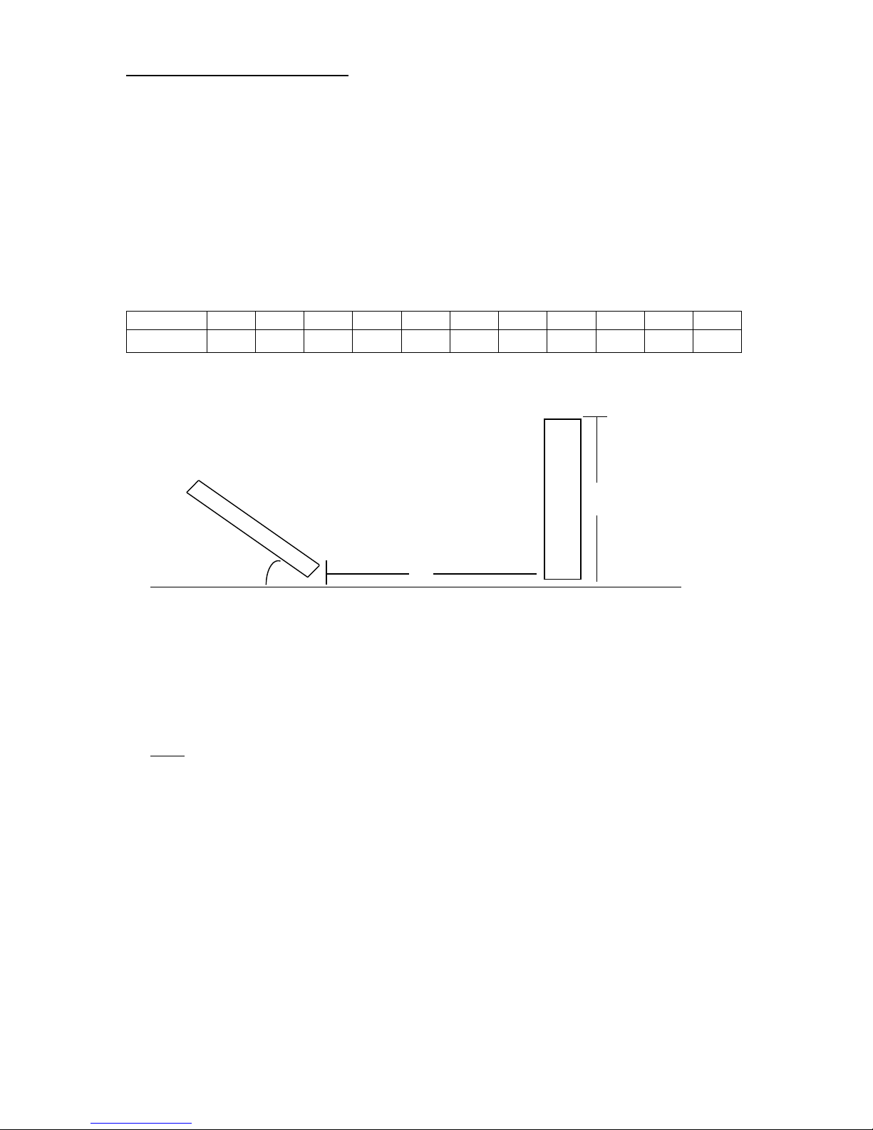
GENERAL INSTALLATION INSTRUCTIONS
• Always make sure that the location chosen for the installation of the solar water heater is not
shaded by any obstacles (walls or other structures, trees and vegetation, other buildings, etc…)
at any moment. It is recommended to ensure at least 4 hours of direct sunlight around mid-day
during the winter solstice. In case of obstacles please observe minimum distance of the
collector(s) from the obstacle, as per the following calculation:
d=h x κ
where: κ=1/ tg(61°-φ) and φ= latitude of installation point.
The table below represents the (κ) coefficients for some latitudes:
LATITUDE 36° 37° 38° 39° 40° 41° 42° 43° 44° 45° 46°
κ (m) 2,144 2,246 2,355 2,475 2,605 2,747 2,904 3,077 3,270 3,487 3,732
In order to calculate the minimum distance (d) of the system from the obstacle one must multiply the
height (h) of the obstacle by the appropriate (κ) coefficient.
For latitudes, other than the ones reported in the table above, the formula must be used in order to
calculate the (κ) coefficient.
• The collectors must face towards the South when installed North of the equator and towards
the North when installed South of the equator. A deviation of up to 30º East or West is tolerated
with a minimum effect on the performance of the system.
Note: a deviation towards the East will result in a greater output of the system until mid-day, while
a deviation towards the West will result in a greater performance of the system in the afternoon.
• The optimal inclination depends on latitude of the installation point. In order to avoid fastidious
calculations, it is recommended as follows:
o If the system is used mainly during summer months: β=φ - (10 to 15)
o the system is used mainly during winter months: β=φ + (10 to 15)
o the system is used all year round: β=φ
Where β is the collector inclination and φ the latitude of the installation point.
• If the Solar System is installed in a location with a pitch lower than 13º or greater than 45º, additional
or different equipment may be necessary.
• Always make sure that all the piping of the primary and secondary circuits, going to and coming from
the Solar Water Heater, are very well insulated, even in hot climate regions and treated for UV
radiation.
h
4
SOLATHERM reserves the right to modify characteristics of the products or their accessories and components without prior notice.
• Always use counter force (opposite force) when installing the tightening fittings (especially olive
fittings) to avoid internal cracking and breaking of copper welds between tubes. Breaking of the
welds due to non-observance of this point is excluded from warranty and will result in cancelation
of the warranty.
• For closed circuit systems, always prepare and mix thoroughly the thermal fluid mixture in a bucket
before filling the system. Never fill the system with thermal fluid and water separately.
• Avoid leaving the Solar System for long periods without using hot water (holidays, prolonged
absences, etc...) due to risks of overheating, or make sure the solar panels are covered during this
period.
WARNING:
IF THE HOT WATER SYSTEM IS NOT USED FOR TWO WEEKS OR MORE, A QUANTITY OF HIGHLY
FLAMMABLE HYDROGEN GAS MAY BE ACCUMULATED IN THE WATER HEATER. TO DISSIPATE THIS GAS
SAFELY, IT IS RECOMMENDED THAT A HOT TAP BE TURNED ON FOR SEVERAL MINUTES UNTIL DISCHARGE
OF GAS CEASES. USE A SINK, BASIN, OR BATH OUTLET, BUT NOT A DISHWASHER, CLOTHES WASHER OR
OTHER APPLIANCE. DURING THE PROCEDURE THERE MUST BE NO SMOKING, OPEN FLAME OR ANY
ELECTRICAL APPLIANCE OPERATING NEARBY. IF HYDROGEN IS DISCHARGED THROUGH THE TAP, IT WILL
PROBABLY MAKE AN UNUSUAL SOUND AS WITH AIR ESCAPING.
• The safety of the system and validity of the warranty are conditioned by the use of genuine
SOLATHERM spare parts and accessories. Please only use genuine SOLATHERM spare parts and
accessories from your nearest SOLATHERM dealer or contact the manufacturer.
SOLATHERM declines any responsibility that may arise from the non-observance of the installation,
maintenance and use instructions herein, non-observance of relevant local norms, regulations and
industry codes, improper or defective installation, or incorrect manipulation of the system or the
accessories composing it.
SOLATHERM STHS SERIES SOLAR WATER HEATER RANGE
Model
Nominal Tank
Volume (lt)
Solar Collector
Model
Absorber
Type
Collector Surface
Weight Empty
(kg)
STHS 80/150
80 EFM 150 1 x 1,50 m2 88
STHS 120/182
120 EFM 182 1 x 1,82 m2 106
STHS 120/182H
120 EFM182H 1 x 1,82 m2 105
STHS 160/182
160 EFM182 1 x 1,82 m2 122
STHS 160/200
160 EFM 200 1 x 2,00 m2 125
STHS 160/200H
160 EFM 200H 1 x 2,00 m2 125
STHS 200/200
200 EFM 200 1 x 2,00 m2 137
STHS 200/200H
200 EFM 200H 1 x 2,00 m2 134
STHS 200/237
200 EFM 237 1 x 2,37 m2 146
STHS 200/237H
200 EFM 237H 1 x 2,37 m2 143
STHS 200/272
200 EFM 272 1 x 2,72 m2 152
STHS 300/364
300 2 x EFM 182 2 x 1,82 m2 201
STHS 300/400
300 2 x EFM 200 2 x 2,00 m
2
206
STHS 300/474
300 2 x EFM 237 2 x 2,37 m2 212
STHS 500/546
500 3 x EFM 182 3 x 1,82 m2 302
STHS 500/600
500 3 x EFM 200 3 x 2,00 m
2
310
STHS 500/711
500 3 x EFM 237 3 x 2,37 m2 333
5
SOLATHERM reserves the right to modify characteristics of the products or their accessories and components without prior notice.
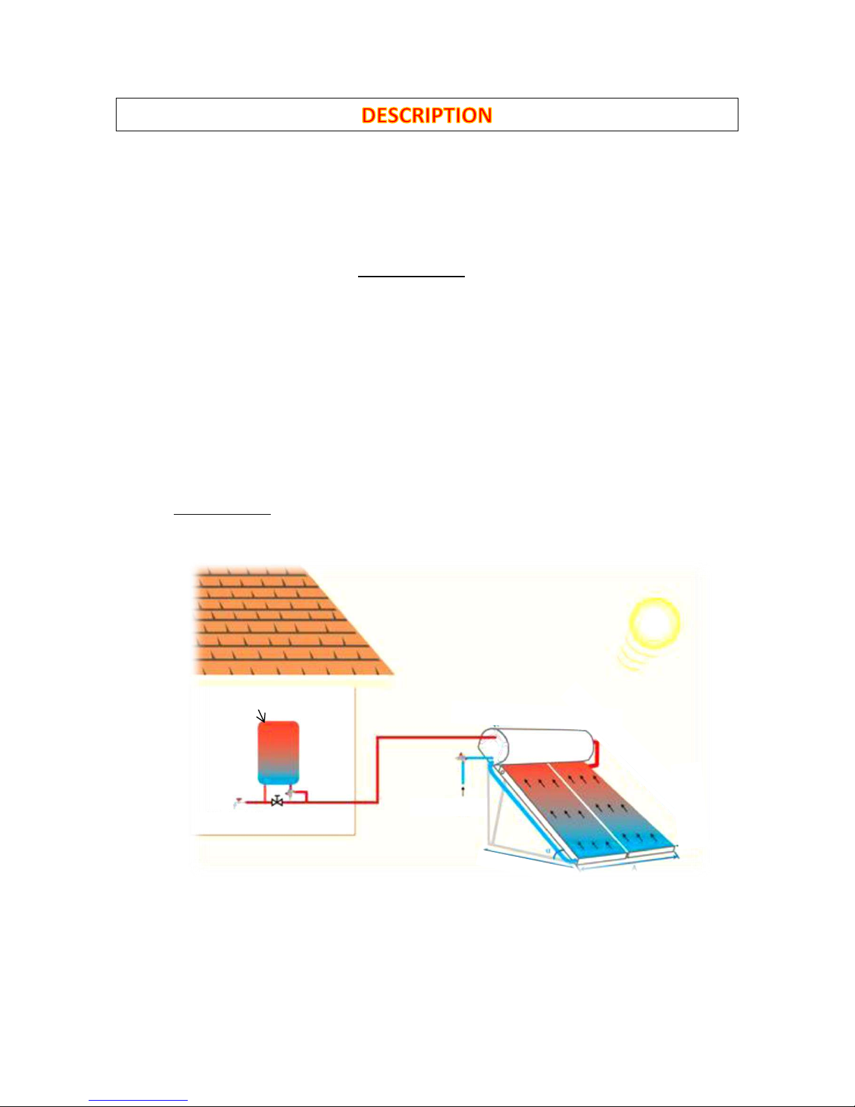
A solar water heater (SWH) is a system that can provide hot water, using the direct and indirect
solar irradiation. It consists from a storage tank where the sanitary water is stored (secondary
loop) and the solar panel(s) (solar collectors) which, along with the annular heat exchanger of
the storage tank (jacket) and the connection pipes connecting them, constitute the primary
circuit.
Heating of the water in based on a natural principle of hot being lighter and less dense than
cold, therefor by stratification, is always at the highest point while cold always sinks below. This
is why these types of solar systems are referred to as Natural Circulation or Thermosiphon
Systems.
In a Solar Water Heater, the thermal fluid (in the primary circuit) is heated by the sun in the
solar panels, getting lighter, so tends to rise up the solar panels, through the connecting pipes
and inside the heat exchanger, where it transfers the heat (calories) to the sanitary water stored
in the storage tank. While it exchanges heat with the sanitary water, the thermal fluids
temperature is lowered, slowly returning back to normal and regaining weight, thus returns by
gravity back to the solar panels to start the heating cycle all over again.
Principle Diagram

6
SOLATHERM reserves the right to modify characteristics of the products or their accessories and components without prior notice.
1. General Characteristics
• Low Iron, Mistlite, Tempered Solar Glass (Security)
• Laser Welded Al/Cu Titanium Selective Absorber 5mm
• Rear Insulation: Rock Wool 40mm
• Copper Headers and Risers
• Aluzinc Rear Cover of the Collector
• Side Insulation: Rock Wool 20mm
• Aluminium Alloy Collector Frame with “Sea Side” Class Treatment
• Maximum Negative Pressure Load 3000Pa

7
SOLATHERM reserves the right to modify characteristics of the products or their accessories and components without prior notice.
2. Technical Characteristics
• Frame: Special aluminium alloy Casing with Electrostatic Treatment
• Absorber Type: Laser Welded Single Sheet Selective Aluminium on Copper Harp (Grid)
• Absorber Surface: Highly Selective Blue Titanium Treatment (α≥ 0,95 +/-0,02, ε≤ 0,05 +/-0,02).
• Headers: Copper tubes Ø 22 mm
• Risers: Copper tubes Ø 8 mm
• Transparent Cover: Low Iron, Securit, Prismatic Solar Glass – Transmissibility: t≥0,91 –
Thickness: 3.2mm or 4mm,
• Back Side Collector Cover: in aluzinc, thickness 0,4 mm with EPDM rubber joint to avoid all
possibility of humidity infiltration.
• Rear insulation: in 40mm thick rock wool - density 50kg/m
3
(0,035W/m k)
• Side insulation: in 20mm thick glass wool - density 70kg/m
3
(0,034W/m k)
• Water tightness: black silicone and EPDM rubber
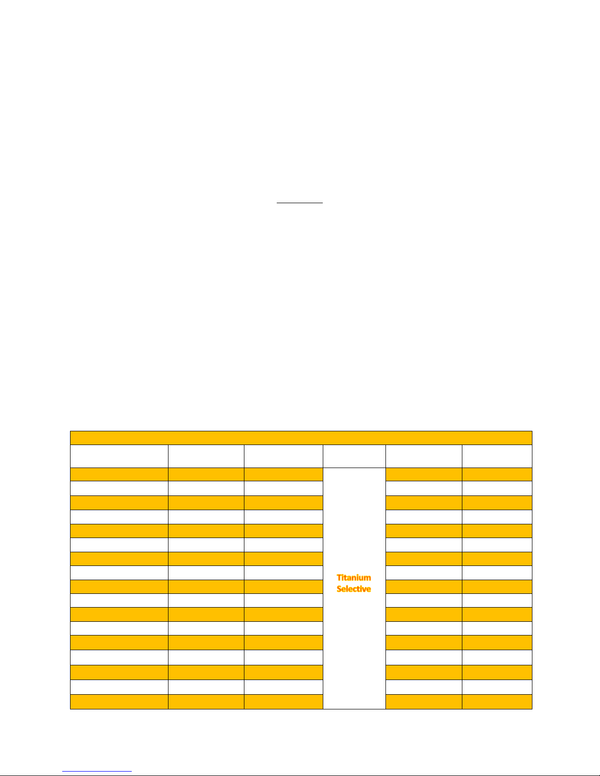
EFM SELECTIVE COLLECTORS TECHNICAL DATA
Model Dimensions
Absorber
Treatment
Number
of Risers
Total
Area (m²)
Aperture
Area (m²)
Volume
(lt)
Weight empty
(kg)
EFM 150
1480x1010x86
Titanium
Selective
9 1,50 1,38 1,21 26,20
EFM 150H
1010x1480x86
Titanium
Selective
14 1,50 1,38 1,56 28,20
EFM 182
1480x1230x86
Titanium
Selective
11 1,82 1,72 1,46 31,50
EFM 182H
1230x1480x86
Titanium
Selective
14 1,82 1,72 1,68 32,00
EFM 200
1980x1010x86
Titanium
Selective
9 2,00 1,86 1,40 34,00
EFM 200H
1010x1980x86
Titanium
Selective
18 2,00 1,86 2,05 34,80
EFM 237
1930x1230x86
Titanium
Selective
11 2,37 2,23 1,70 41,50
EFM 237H
1230x1930x86
Titanium
Selective
18 2,37 2,23 2,20 42,50
EFM 272
2160x1260x86
Titanium
Selective
11 2,72 2,57 1,82 47,50
EFM 272H
2160x1260x86
Titanium
Selective
19 2,72 2,57 2,30 48,50
TITANIUM SELECTIVE COLLECTORS DATA
• Instant Efficiency* 0: 0,830
• First degree heat loss* α1: 3,93W/m²K
• Second degree heat loss*: α2: 0,015W/m²K
2
• Stagnation temperature (at 1000 W/m² at 30°C): 231,09°C
• Effective Thermal Capacity: 10.85 kJ/(m
2
K)
Flow Rate: 0.021kg/(s m2)
Irradiance G=1000W/m2 – Ambient temperature Ta= 30°C
*Compared to collector aperture area as per EN12975 – Solar Keymark Certification

8
SOLATHERM reserves the right to modify characteristics of the products or their accessories and components without prior notice.
1. Enamelled Storage Tank (Boiler) General Characteristics
2. Enamelled Storage Tank (Boiler) Technical Characteristics
3. Primary Circuit Connecting Piping (Between Storage Tank and Collectors)
• Material: 316 L Stainless Steel
• Insulation: ISOPIPE UV - thickness: 13mm
TECHNICAL DATA OF EGBM ENAMELED STORAGE TANKS
GLASS LINED EGBM 80 EGBM 120 EGBM 160 EGBM 200 EGBM 300 EGBM 500
Capacity (lt) 76 117 156 197 296 468
Max. operating pressure (bar) 10 10 10 10 10 10
Pressure Test (bar) 15 15 15 15 15 15
Max. working Temp. (°C) 99 99 99 99 99 99
Tank Dimensions ΦxL (mm) 530x960 580x915 580x1116 580x1356 580x1970 700x2120
Jacket capacity (lt) 5,0 8,6 12,9 18,3 25,8 30
Jacket Heat exchanger surface (m2) 0,53 0,62 0,91 1,28 1,79 2,1
Weight empty (kg) 43 54,9 66,8 81,8 114,5 160
1. Storage tank: low carbon steel, thickness: 2,5mm
2. Internal Protection Treatment: double glass enamel
internal coating, backed at 860ºC, as per German
standards DIN 4753/3
3. Heat Exchanger: Jacket type made of low carbon
steel, thickness 1,5mm.
4. Thermal Insulation: high density (>50kg/m³),
ecological (CFC free), incombustible expansive CFC
free polyurethane foam, thickness 50mm
4. External casing: made of hot dipped galvanized
steel with electrostatic powder coating treatment
5. Accessibility: Large Side flange (man hole) for inspection and maintenance. Position of anode and electrical back-up element
6. Anodic protection: 2 large magnesium rods (anodes) for protection against corrosion and electrolysis
7. Safety / Overheating Protection: 2 BAR safety Valve (or Expansion Vessel) Connection Outlet made of Stainless Steel: BSP ½’’ M
8. Jacket Heat Exchanger Outlet: made of Stainless steel BSP: ¾’’ M
9. Jacket Heat Exchanger Inlet: made of Stainless steel: BSP ¾’’ M (Also acts as filling point for the closed circuit of the system. Must be
plugged after filling)
10. Domestic Hot Water Outlet: made of Stainless Steel: BSP ¾’’ M
11. Cold Water Inlet: made of Stainless Steel: BSP ¾’’ M
12. Electrical back-up Heating Element: power rate according to local norms and regulations of the country of destination
13. Safety Thermostat with Bipolar Protection and Auxiliary Fuse: All Electrical components carry CE marking as per EN 60335-1 and
EN660335-2-21 standards.
14. Cable Gland and Cable Tube: Water Resistant Passage for the Electric Element Connection Cable
5
7
8
4
3
10
9
2
1
6
12
13
11
14

9
SOLATHERM reserves the right to modify characteristics of the products or their accessories and components without prior notice.
Note: All Systems are accompanied by the Installation instructions for the Mounting Structure
included in the kit.
SOLATHERM Thermosiphon Solar Systems are available with a variety of different mounting structures
in order to fit and adapt to all possible situations, inclinations and environment.
They are adapted for installations on:
• Ground
• Flat roof
• Roof with Clay or Concrete Tiles
• Roof with Asphalt Shingles
• Roof with Slates
• Roof with Wood Shingles and Shake
• Roof with Synthetic Roofing Products
• Sheet Metal roofing
Available Mounting Structure Materials:
• Hot dipped galvanized steel
• Powder coated galvanized steel
• Aluminium
Available inclinations include:
• 45° inclination for flat roof
• 38° inclination for flat roof
• 25° inclination for flat roof
• 15° inclination for flat roof
• Any pitched roof inclination between 45° and 13°
• For pitched roofs with an inclination above 45° or lower than 13° are upon request
Inclination 45°: H= 1770mm to 2030mm depending on the system
Inclination 38°: H= 1570mm to 2015mm depending on the system
Inclination 15°: H= 600mm to 860mm depending on the system
Inclination 25°: H= 1400mm to 1550mm depending on the system
Inclination identical to pitched roof
between 15° and 45°
10
SOLATHERM reserves the right to modify characteristics of the products or their accessories and components without prior notice.
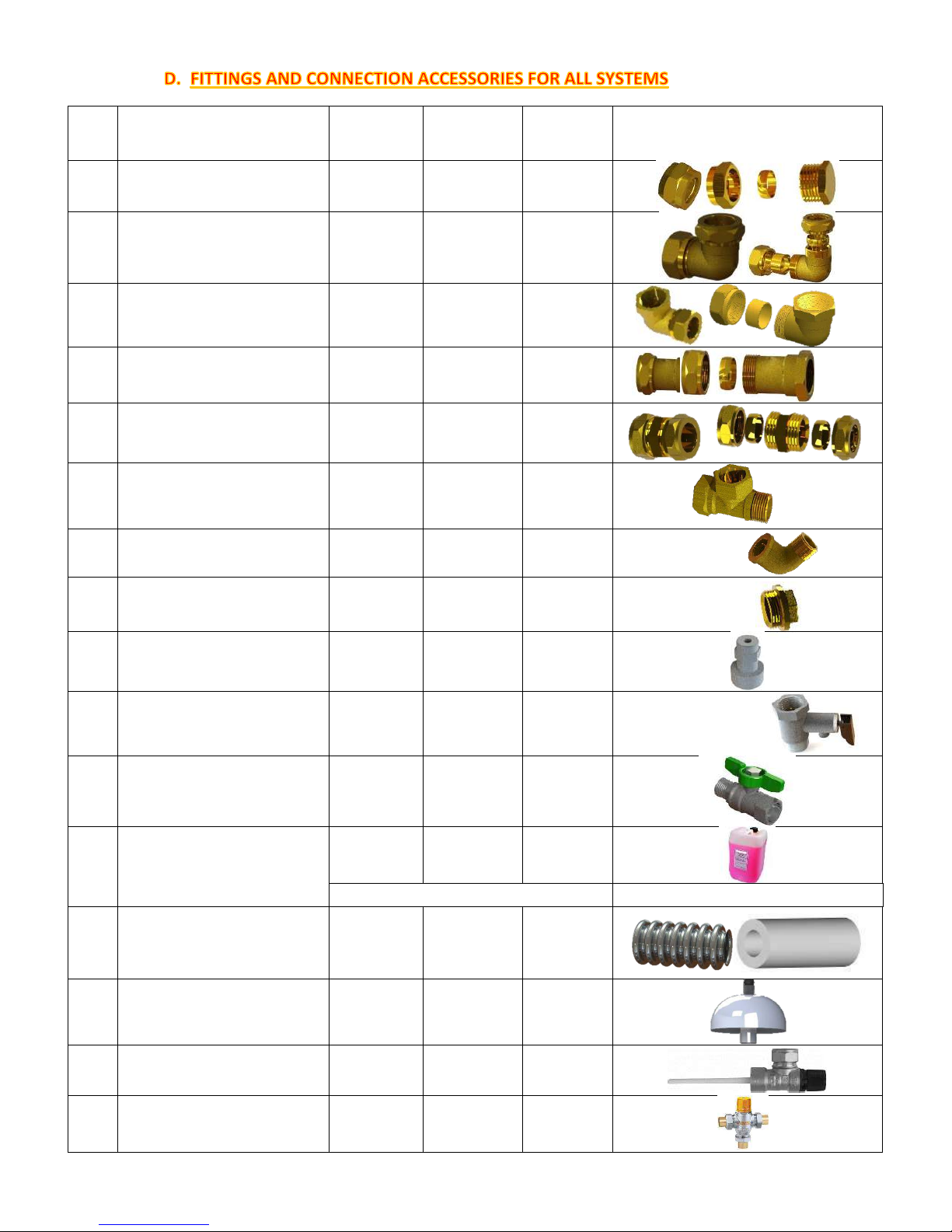
Piece
No.
DESCRIPTION
Qty FOR 1
COLLECTOR
SYSTEMS
Qty FOR 2
COLLECTOR
SYSTEMS
Qty FOR 3
COLLECTOR
SYSTEMS
SAMPLE DRAWING
1
PLUG FOR COPPER TUBE Ø22
MECHANICAL TIGHTENING
2 2 2
2
ELBOW FITTING FOR COPPER
TUBE Ø22 MECHANICAL
TIGHTENING X INOX TUBE
2 2 2
3
ELBOW FITTING FOR
3/4’’FEMALE x DN16 SS TUBE
1 2 1
4
STRAIGHT FITTING FOR
3/4’’FEMALE X INOX TUBE
1 --- 1
5
STRAIGHT FITTING FOR Φ22mm
COPPER TUBE
--- 2 4
6
TEE FITTING 3/4" MALE x 3/4”
FEMALE x 3/4" FEMALE
1 1 1
7
ELBOW FITTING MALE 1/2" x
1/2" FEMALE
1 1 1
8 MALE PLUG 3/4" 1 1 1
9
SAFETY VALVE 2 BAR FOR CLOSE
LOOP CIRCUIT
1 1 1
10
SAFETY NON RETURN VALVE 9
BAR FOR INLET OF CITY COLD
WATER
1 1 1
11
BALL VALVE 1/2’’ MALE X 1/2’’
FEMALE
1 1
1
12 ANTIFREEZE LIQUID
2lt 3lt 6lt
(depending on local climatic conditions)
13
STAINLESS STEEL TUBES
INSULATED WITH UV PROTECTED
INSULATION (Short for HOT +
Long
for COLD)
2 2 2
14
EXPANSION VESSEL 1Lt FOR
CLOSE CIRCUIT
1 (Optional) 1 (Optional) 1 (Optional)
15
TEMPERATURE-PRESSURE
VALVE (95°C-10 BAR)
1 (Optional) 1 (Optional) 1 (Optional)
16 THERMOSTATIC MIXING VALVE 1 (Optional) 1 (Optional) 1 (Optional)

11
SOLATHERM reserves the right to modify characteristics of the products or their accessories and components without prior notice.
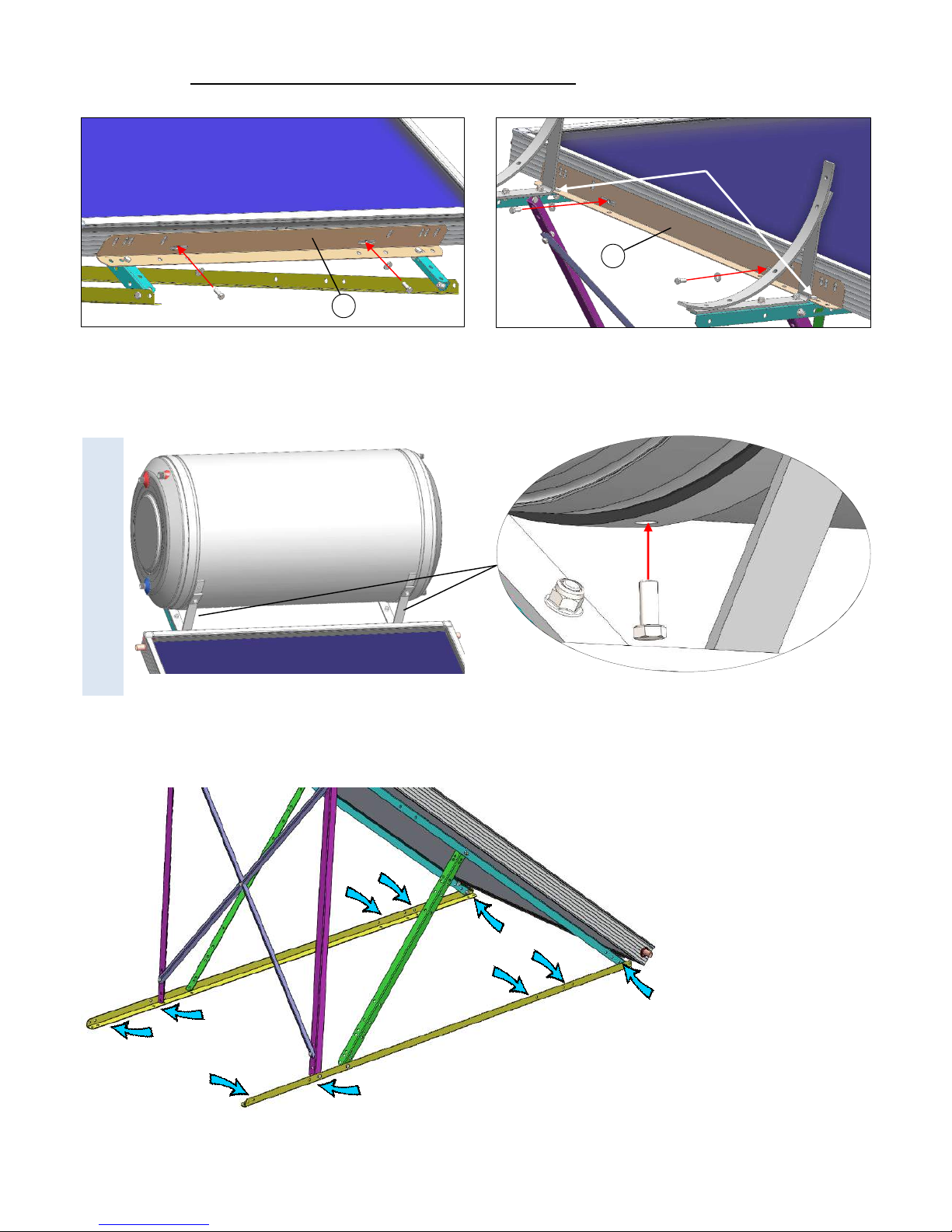
1. General Characteristics
2. Common Steps for all systems with 1 collector of 2,00m
2
or 2,37m2
Νo. Description Qty
1 “L” shaped brackets 2420mm 2
2 “L” shaped brackets 2085mm 2
3 “L” shaped brackets 1320mm 2
4 “L” shaped brackets 955mm 2
5 Cross brackets 1430mm 2
6 “L” shaped brackets 1000mm 2
7 Tank support brackets 2
8 Rubber cover of tank support brackets 2
9 Hexagonal Bolt M8x20 29
10 Hexagonal Bolt M8x30 4
11 Hexagonal Nut M8 27
12 Washers Φ8.5 4
13 Anchor bolt M8X60 6
14 Plastic Anchor M8X60 6
STHS120/200 STHS120/237 STHS160/200 STHS160/237 STHS200/200 STHS200/237
C 660mm 660mm 850mm 850mm 940mm 940mm
W 1130mm 1385mm 1250mm 1385mm 1490mm 1490mm
W
C
1
2
3
4
5
6
7
8
1
3
4
2
Step 1: Assemble the Side Brackets using
M8x20 Bolts and Nuts
5
3
Step 2: Form the Rear
Cross using the 2
brackets No.5 and
Connect the 2 side
brackets between them
using M8x20 Bolts and
nuts.
The exact connection
point between them
depends on the model
(120lt, 160lt or 200lt)
please refer to the
appropriate model
connection details in
the following pages.
Lower collector support bracket No. 6
6
Step 3: Connect the Lower and
Upper Collector Support Brackets
No.6 with the Side Brackets using
M8x20 Bolts and nuts but do not
tighten.
The exact connection point between
them depends on the model (120lt,
160lt or 200lt) please refer to the
appropriate model connection
details in the following pages.
Upper collector support bracket No. 6
6

12
SOLATHERM reserves the right to modify characteristics of the products or their accessories and components without prior notice.
M8x30
2nd hole on
Nr.3
3. Connection details for STHS 120/2,00m
2
and 120/2,37m2 Systems
7
M8x30
8
Step 4: Connect the Tank Support
Brackets No.7 to the Side Brackets
No.1 using the M8x20 and M8x30
nuts and bolts as indicated above.
1
Step 5: After both Tank
Support Brackets No.7 are
installed fit the Rubber
Covers No.8 to avoid
scratching and damaging
the tank.
8

13
SOLATHERM reserves the right to modify characteristics of the products or their accessories and components without prior notice.
4. Connection details for STHS 160/2,00m
2
and 160/2,37m2 Systems
5. Connection details for STHS 200/2,00m
2
and 200/2,37m2 Systems
4
th
hole on
Nr.3
M8x30
M8x30
Oval hole
on Nr.3
8
8
14
SOLATHERM reserves the right to modify characteristics of the products or their accessories and components without prior notice.
6. Collector and Tank installation on the Mounting Structure
6
Tighten No.6 with No.1
after collector is fixed
6
Install the Collector and Secure it with the Lower and Upper Collector Support Brackets No.6 as indicated
in the drawing
above using M8x20 bolts and washers, and tighten upper Collector Support Bracket Nr.6 with Support brackets Nr.1.
Install the Tank making sure the cold-water inlet is on the left side when looking at the system from the
front.
Connect the Tank to the Mounting structure through the Tank Support Brackets as indicated on the picture above
using M8x20 bolts through the middle strip’s hole into the tanks rivets.
Attention:
This side on the left
Choose the most convenient
holes provided on the
horizontal
brackets No.2
(preferably on
the edges and
center) and secure the system
to the ground using the
six
plastic anchors and anch
or
screws M8x60 provided.
15
SOLATHERM reserves the right to modify characteristics of the products or their accessories and components without prior notice.
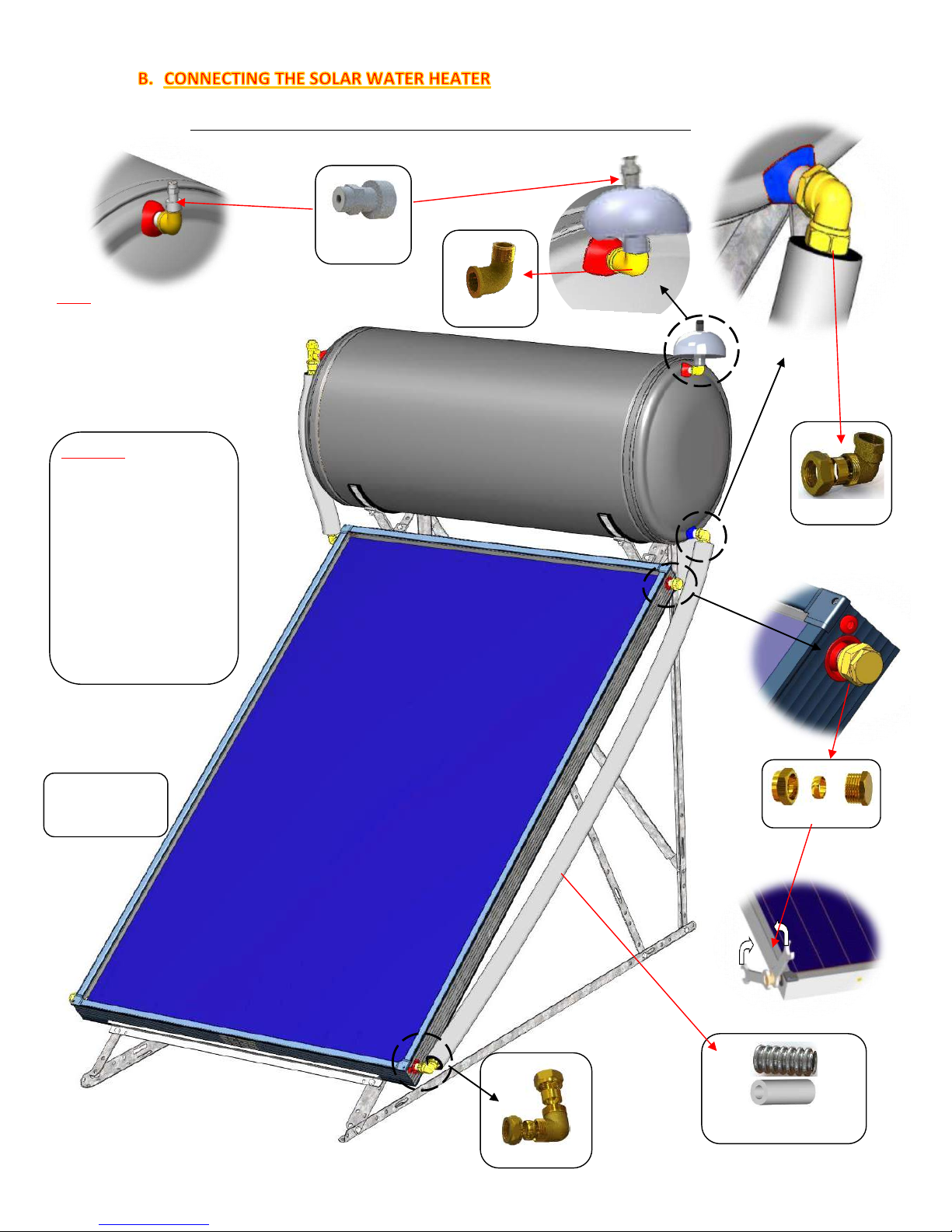
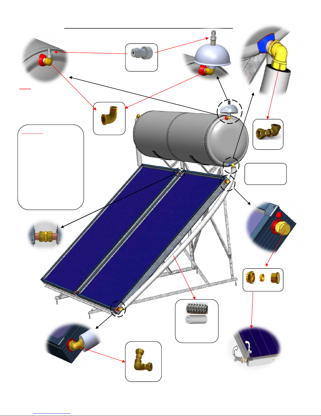
1. HYDRAULIC CONNECTIONS OF THE CLOSE CIRCUIT (1 COLLECTOR SYSTEMS)
ATTENTION: when placing the
brass fittings with mechanical
tightening on the Ø22 copper
tubes of the collector do it
carefully in order not to rotate
the copper tuber. If the copper
tube is rotated, it can cause
damage to the absorber and
break the wildings between
the vertical tubes (risers) with
the Ø22 tubes (headers), which
will not be covered by the
warranty. Opposite force is
necessary to avoid damage!
SAFETY VALVE
No.9
FITTING No. 2
RIGHT FRONTAL
VIEW OF THE
SOLAR SYSTEM
LONG STAINLESS STEEL
TUBE & INSULATION No.
FITTING No.1
FITTING No.7
FITTING No. 3
Note: If the (optional) Expansion
Vessel (No.14) is not includes in the Kit
then then the Safety Valve Nr.8 must
be placed directly on the Fitting No.6
16
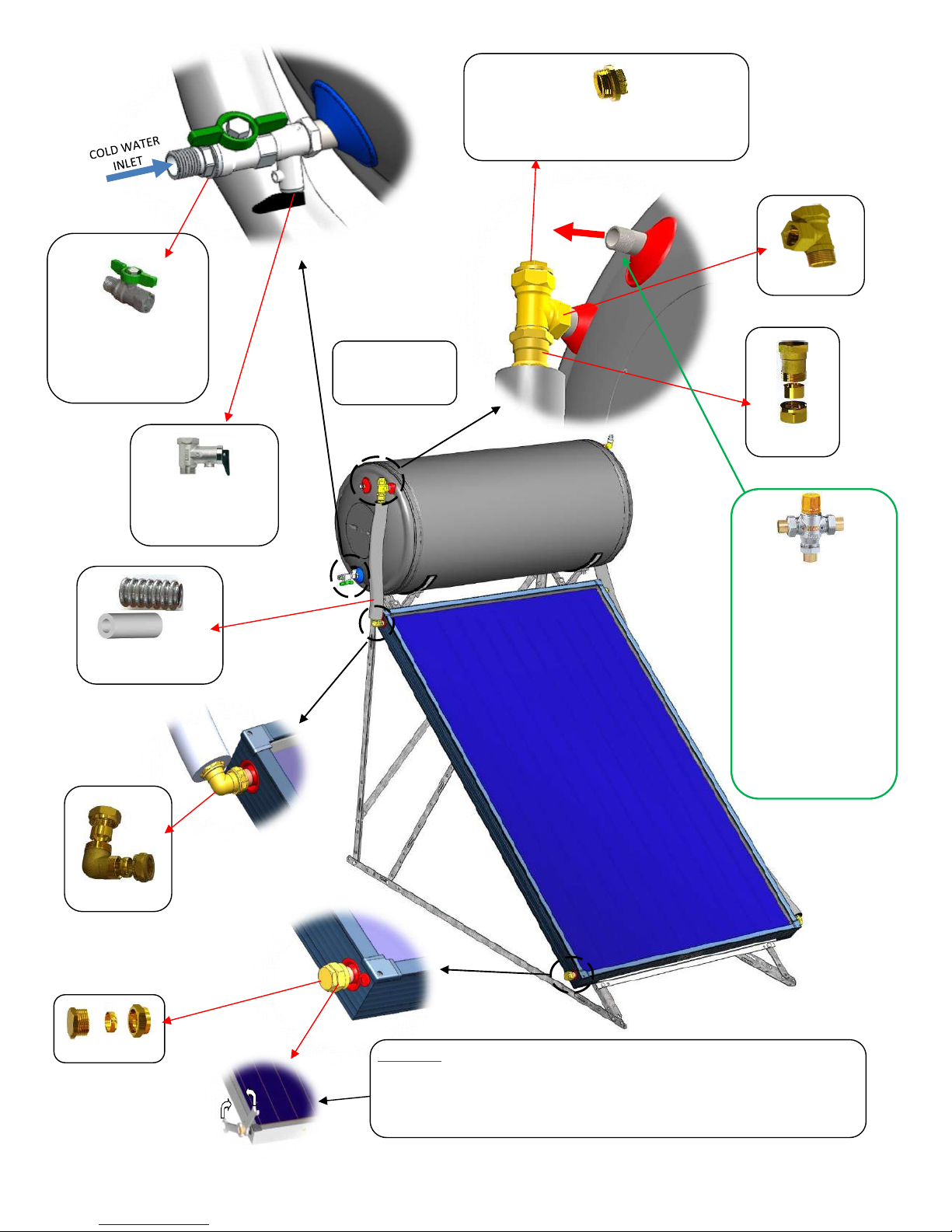
SOLATHERM reserves the right to modify characteristics of the products or their accessories and components without prior notice.
FITTING No.1
SAFETY/NON-RETURN
VALVE No.10 is placed
on the cold-water inlet
LEFT FRONTAL
VIEW OF THE
SOLAR SYSTEM
The THERMOSTATIC
MIXING VALVE No. 16
(OPTIONAL) is placed after
the HOT WATER OUTELT as
per instructions included
in the mixing valve, in
order to limit the hot
water temperature
delivered to the Tap and
avoid burning. It is
recommended that the hot
water delivered at the Tap
is limited to 50°C.
SHORT
STAINLESS STEEL TUBE
& INSULATION No. 13.
BALL VALVE ½’’MALE X ½’’
FEMALE No.11 is installed
right after the Safety/Non-
Return Valve No 10.
FITTING Nr. 6
FITTING No.8: Plug it only after closed loop is
filled with the thermal fluid/water mixture (see
“filling the closed circuit” section D2)
FITTING No. 4
HOT WATER
OUTLET
ATTENTION: when placing the brass fittings with mechanical tightening on the Ø22 copper
tubes of the collector do it carefully in order not to rotate the copper tuber. If the copper
tube is rotated, it can cause damage to the absorber and break the wildings between the
vertical tubes (risers) with the Ø22 tubes (headers), which will not be covered by the
warranty. Opposite force is necessary to avoid damage!
FITTING No. 2
17
SOLATHERM reserves the right to modify characteristics of the products or their accessories and components without prior notice.
2. HYDRAULIC CONNECTIONS OF THE CLOSE CIRCUIT (2 COLLECTOR SYSTEMS)
FITTING No.1
ATTENTION: when placing the
brass fittings with mechanical
tightening on the Ø22 copper
tubes of the collector do it
carefully in order not to rotate
the copper tuber. If the copper
tube is rotated, it can cause
damage to the absorber and
break the wildings between the
vertical tubes (risers) with the
Ø22 tubes (headers), which will
not be covered by the warranty.
Opposite force is necessary to
avoid damage!
FITTING No. 2
RIGHT SIDE
FRONTAL VIEW
OF THE SOLAR
INOX TUBE &
INSULATION No. 13
FITTING No. 3
SAFETY VALVE
No.9
FITTING No.7
Note: If the (optional)
Expansion Vessel (No.14) is
not includes in the Kit then
then the Safety Valve Nr.8
must be placed directly on
the Fitting No.7

18
SOLATHERM reserves the right to modify characteristics of the products or their accessories and components without prior notice.
FITTING No.1
SAFETY NON-RETURN
VALVE No.9
LEFT FRONTAL
VIEW OF THE
SOLAR SYSTEM
BALL VALVE ½’’MALE X ½’’
FEMALE No.10 (IF
INCLUDED IN THE KIT) IS
INSTALLED RIGHT AFTER
THE SAFETY NON-RETURN
The THERMOSTATIC MIXING
VALVE No. 16 (OPTIONAL) is
placed after the HOT WATER
OUTELT as per instructions
included in the mixing valve,
in order to limit the hot water
temperature delivered to the
Tap and avoid burning. It is
recommended that the hot
water delivered at the Tap is
limited to 50°C.
FITTING No. 4
COPPER TUBE &
INSULATION
No.13
FITTING No. 2
FITTING No. 6
COLD INLET
FITTING No. 3
FITTING No. 8 Attach it after close loop
is filled with heat transfer medium
(see “close loop filling” in this manual)
ATTENTION: when placing the brass fittings
with mechanical tightening on the Ø22
copper tubes of the collector do it carefully
in order not to rotate the copper tuber. If
the copper tube is rotated, it can
cause
damage to the absorber and break the
wildings between the vertical tubes (risers)
with the Ø22 tubes (headers), which will not
be covered by the warranty. Opposite force
is necessary to avoid damage!
19
SOLATHERM reserves the right to modify characteristics of the products or their accessories and components without prior notice.
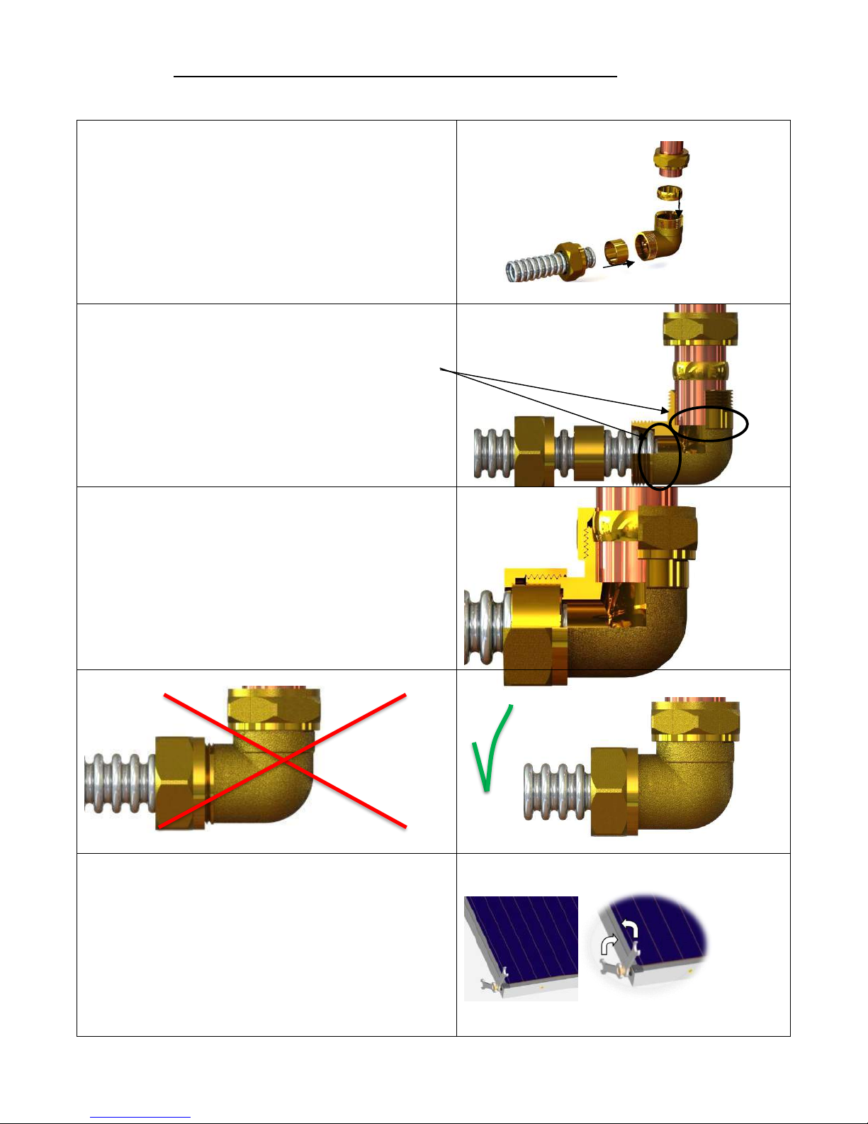
3. ASSEMBLY OF FITTINGS WITH THE STAINLESS STEEL CORRUGATED TUBES
STEP 1: INSERT THE Φ22 COPPER NUT AND THEN THE RING
FOR COPPER FITTING ON THE COPPER TUBE AND THE DN16
INOX NUT AND THEN THE RING FOR INOX DN16 ON THE
STAINLESS STEEL FLEXIBLE TUBE.
STEP 2: INSERT STAINLESS STEEL FLEXIBLE TUBE IN THE MAIN
CORP OF THE ELBOW FITTING, UNTIL THE TUBE CAN’T GO
FURTHER IN. REPEAT THE SAME THING FOR COPPER TUBE.
STEP 3: TIGHTEN BOTH NUTS.
CAUTION: TAKE EXTRA CARE ON THE FLEXIBLE TUBE NUT.
THE THREADS ON THE FITTING’S BODY MUST BE FULLY
COVERED BY THE NUT (SEE BELOW).
ATTENTION: When tightening the fittings on collectors the
copper tubes always do it carefully in order not to rotate the
copper tube Ø22 of the collector. If the copper tube is rotated,
the welds between the copper risers and Ø22 copper headers
can be broken, resulting in a permanent damage to the
collector. It is imperative to always use opposite force
(counter force) to avoid damage!
20
SOLATHERM reserves the right to modify characteristics of the products or their accessories and components without prior notice.
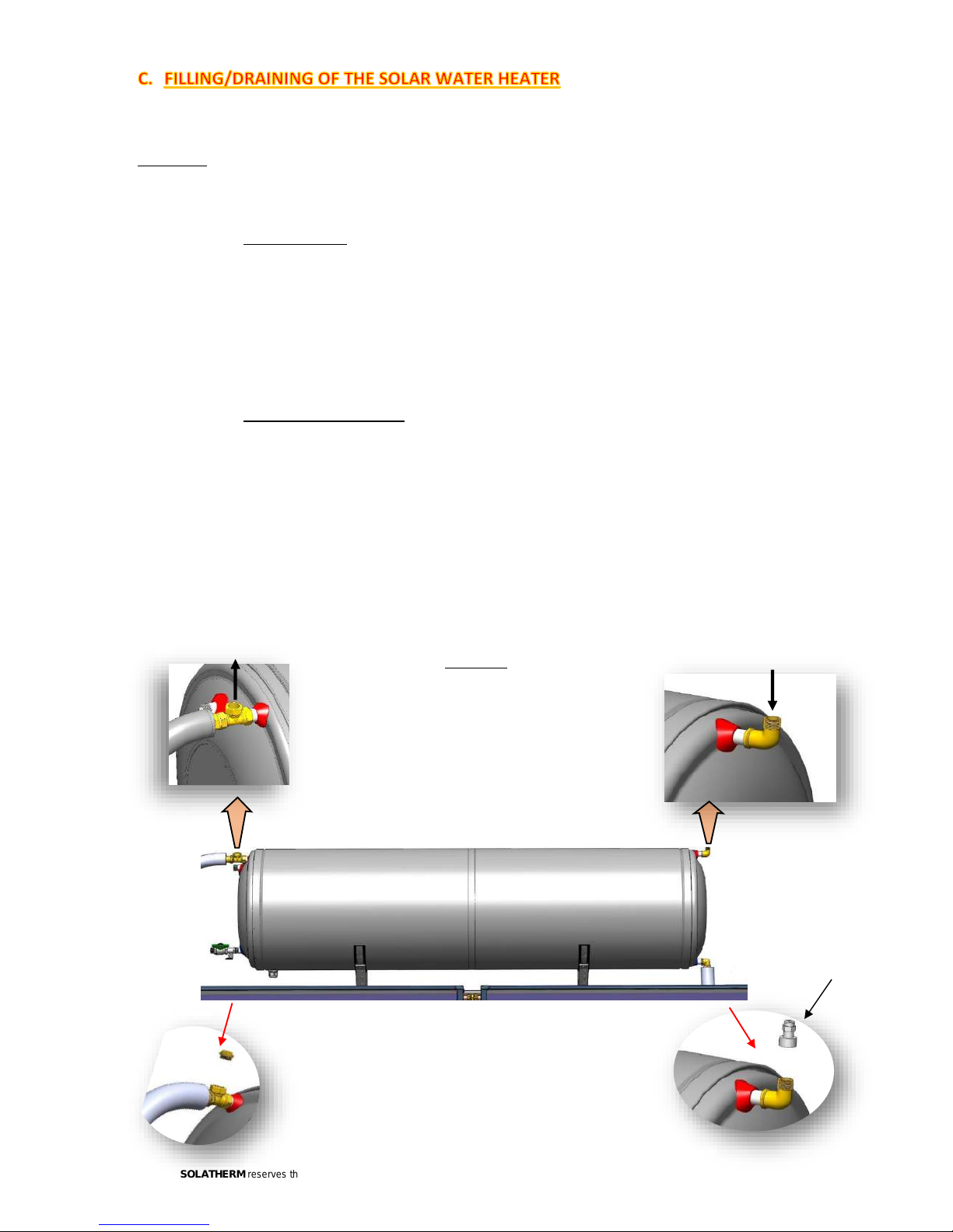
For the filling and draining of the system, please follow carefully the following steps:
Attention: Always fill the tank with water before filling the closed circuit with the thermal fluid
mixture. Similarly, when draining the system, always drain the closed circuit before emptying the tank
of water.
1. Filling the tank:
Fill the tank with water by opening a hot water tap somewhere in the house and the BALL VALVE (No.10) on
the cold-water inlet of the tank.
Once the tank is full, close the tap inside the house and proceed to the filling of the closed circuit with
the thermal fluid/water mixture. Closed circuit is filled
Note: If water hardness is above 250ppm or if the water is not very clean, it is recommended to install a
water filter. Above 400ppm, a water softener is advised.
2. Filling the closed circuit:
Use a bucket in order to mix the thermal fluid with purified water before filling the solar system. Always
put the thermal fluid in the bucket before the water and mix thoroughly.
Place the bucket with the mixture above the tank and fill the system through the outlet where the safety
valve (No.9) or expansion vessel (No.14) will be fitted, on the top right side of the tank.
The system will be full when the mixture starts coming out the outlet on the other side of the tank where
fitting No.8 is placed. At this point plug and tighten fitting No.8. Shake the system so that any eventual
air bubbles that are trapped can exit through the filling valve and complete with more thermal fluid
mixture until fluid is spilled. Install the safety valve (2 bar) and plug on the outlets.
Closed circuit filling
inlet
Loop is filled when water
flows from the outlet
Procedure
1. Mix thermal fluid with water in a bucket and start the
filling process. The use of a funnel is recommended
for ease of filling.
2. When all thermal fluid is inserted, continue filling
with water. It may take some time, do not rush or air
can be trapped in the system and the process will
take much longer.
3. When the closed circuit is filled, plug the fill-in fitting
with the ¾” male plug (image on the left) and install
the safety valve or expansion vessel with safety valve
if included (image on the right)
Safety Valve or
Expansion Vessel
connection

21
SOLATHERM reserves the right to modify characteristics of the products or their accessories and components without prior notice.
The percentage of thermal fluid to be used in the mixture depends on the table below (Percentage of
thermal fluid/water depending on the minimum ambient temperatures). The solar system must be
protected from frost; thus, it is important to know the minimum temperatures in the region.
For draining of the system use the same steps backwards.
Attention: Avoid filling/draining the system when under solar radiation, due to severe risks of burning
and thermal shocks that may be caused to the system, due to high collector temperatures. Thermal
shocks may damage the absorber of the collectors and non-observance of this warning may result in
cancelation of the product warranty. If filling/draining of the system under solar radiation cannot be
avoided, then it is imperative that the collectors be covered and shaded from the sun.
1. General
The solar water heater is equipped with an electric element and a built-in thermostat (factory
programmed at 60ºC), under the protective cap on the left-hand side of the tank, on the metallic flange
(apparatus plate). On the same flange one of the 2 magnesium rods (anode) is also installed [picture 1].
Note:
a) Electrical connections should be carried out by a qualified electrician and in accordance with local
norms and regulations for each particular application.
b) The mains switch must be switched off throughout the electrical connection procedure and servicing
of the solar systems.
c) Even in the case that the electrical element is not connected, always connect the ground cable either
directly to the ground or on the mounting structure of the system.
d) The heating element must be switched OFF when storage tank is empty. It can cause damage to the
tank and also severe burning. In such a case the warranty of the heating element will be invalid.
e) A safety relay for protection against electrical shock should be fitted.
f) Do not adjust the thermostat temperature above the 60 °C.
Attention: In these cases, the manufacturer’s warranty will not be valid.
Note: all elements comply with EN 60335-1 and EN 60335-2-21 safety regulations
Percentage of thermal fluid/water depending on the minimum ambient temperatures
Thermal fluid [%]
10 16 20 26 30 36 40 45 50
Freezing Point
-4 -6 -8 -12 -15 -20 -24 -30 -36

22
SOLATHERM reserves the right to modify characteristics of the products or their accessories and components without prior notice.
2. Connection instructions
a) Remove the protective cap which covers the electrical components.
b) Connect with 3x4mm² section cable (for heating element). The cable should pass through the plastic
spiral tube located at the Protective Cap and through the cable gland located on the cap.
c) Connect the black wire to the L (Phase) connector, the blue wire to the N (Neutral) connector and
the yellow-green cable to the M4 screw (Ground) marked with ground symbol.
d) Adjust thermostat to the desired temperature (not more than 60°C).
e) Put back in place the electrical connections cover.
f) Connect the other side of the cable to the power.
3. Anti-freeze protection
In areas subject to freezing, adjust the thermostat to position 1, in order to allow the heating element
to turn ON and protect the tank from frost. Always connect the back-up element directly to electricity
with an independent cable and provide a switch.
1. General maintenance
In order to ensure the constant well-functioning of the system, SOLATHERM solar water heater must be
reviewed and maintained periodically (see warranty sheet) and the warranty sheet accompanying must
be completed accordingly by the installer.
All installations and maintenance must be performed by qualified and certified professionals, following
all relevant local norms and regulations (1), industry codes, and according to the manufacturer’s
instructions.
Revisions consists by the optical and physical inspection of the tightness of all connections (hydraulic
and electrical), verification that all safety valves, pressure reducing valves and mixing valves are working
properly (safety valves on primary and secondary circuit), and cleaning of the glass cover.
2. Replacing the sacrificial anodes (magnesium rods)
For optimal protection of the system against electrolysis, all SOLATHERM tanks include 2 magnesium
rods (sacrificial anodes) on each side of the tank, which must be checked and replaced if necessary at
least every 26 months depending on the quality of the water. The size of the anode varies depending
on local norms and requirements. For replacing the anode, proceed as follows:
• Shut down the main power supply
• Remove the safety valves (2,5 bar) or expansion vessel.
• Empty the tank.
• Remove the protective cover of the flange.
• Pull out the thermostat with caution.
• Remove the flange (apparatus plate) and unscrew the anode. Screw-on a new anode and following
the same procedure backwards prepare and set the system back to work.
Sacrificial Anode (Magnesium Rod)

23
SOLATHERM reserves the right to modify characteristics of the products or their accessories and components without prior notice.
In case the Solar Water Heater does not produce enough hot water, please verify the following:
1. That all hydraulic connections of the system are water tight and there are no leaks.
2. That there are no leaks on the taps or on the piping of the building
3. That the collectors are not dirty, or covered with leaves or dust, or shaded. Clean them.
4. If the level of the thermal fluid in the system is not too low. Set to level filling with thermal fluid
mixture through the fluid inlet where the safety valve or expansion vessel is placed.
5. That the stainless-steel tubes connecting the collector(s) to the tank are not bent twisted nor
have any angles. The must be always rising, with no elbows, from collector(s) to tank.
6. That there is no air trapped in the closed circuit of the system. A single bubble can stop
circulation and heat transfer.
7. That the system is level, not leaning towards one side.
8. That the supply of cold and hot water is not connected.
9. That the temperature set on the mixing valve is not too low (below 50ºC depending on local
regulations)
10. If the electric back-up is working. In case it is not working please check the following:
• That the main power supply is ON
• That the thermostat is not set too low
• That the back-up element is not on security mode. The security button must be pushed-in
• That the thermostat and back-up element are not damaged
• That the back-up element wiring is properly connected and to the relevant terminals
If problems persist, then please consider:
a) That the weather conditions allow the proper heating of the system
b) The hot water consumption does not exceed the solar system’s capacity, or the consumers’
expectations of are not above this capacity.
c) The consumer has understood the use of the electrical back-up
Note: all verifications and interventions must be carried out by qualified and certified personnel.
All installations and decommissioning must be performed by qualified and certified
professionals, following all relevant local norms and regulations (1), industry codes, and
according to the manufacturer’s instructions.
Always respect the following order:
• Disconnect all electrical connections (if any)
• Disconnect and empty the pipes and the closed circuit
• Empty the water from the tank
• Dismount the tank first and the collectors after
• Disassemble the brackets.

24
SOLATHERM reserves the right to modify characteristics of the products or their accessories and components without prior notice.
* Solar-Only: only solar energy without back-up heating element or any other source of energy
CALCULATIONS ARE EXECUTED ACCORDING TO THE ANNEX D OF SOLAR KEYMARK -
“SPECIFIC SCHEME RULES”
TESTING LABORATORY NCSR DEMOKRITOS – REPORT CODE: 6082-F1
Thermosiphon System: STHS 120/182
Performance Indicators for Solar-Only* Systems on Annual Base for a Demand Value of 110 lt/day
Location (Latitude) Qd (MJ) QL (MJ) f
sol
(%)
Stockholm (59.2°N) 6150 2870 46.8
Würzburg (49.5°N) 5897 2952 50.1
Davos (46.5°N) 6654 4226 63.6
Athens (38.0°N) 4573 3658 80.0
Thermosiphon System: STHS 160/200
Performance Indicators for Solar-Only* Systems on Annual Base for a Demand Value of 140 lt/day
Location (Latitude) Qd (MJ) QL (MJ) f
sol
(%)
Stockholm (59.2°N) 7821 3311 42.3
Würzburg (49.5°N) 7506 3500 46.8
Davos (46.5°N) 8483 4920 58.2
Athens (38.0°N) 5834 4447 76.4
Thermosiphon System: STHS 200/200
Performance Indicators for Solar-Only* Systems on Annual Base for a Demand Value of 200 lt/day
Location (Latitude) Qd (MJ) QL (MJ) f
sol
(%)
Stockholm (59.2°N) 11164 3813 34.2
Würzburg (49.5°N) 10691 4131 38.6
Davos (46.5°N) 12110 5645 46.6
Athens (38.0°N) 8326 5550 66.7
Thermosiphon System: STHS 200/237
Performance Indicators for Solar-Only* Systems on Annual Base for a Demand Value of 200 lt/day
Location (Latitude) Qd (MJ) QL (MJ) f
sol
(%)
Stockholm (59.2°N) 11164 4320 38.7
Würzburg (49.5°N) 10691 4636 43.4
Davos (46.5°N) 12110 6433 53.2
Athens (38.0°N) 8326 6023 72.4
Thermosiphon System: STHS 300/364
Performance Indicators for Solar-Only* Systems on Annual Base for a Demand Value of 300 lt/day
Location (Latitude) Qd (MJ) QL (MJ) f
sol
(%)
Stockholm (59.2°N) 16746 6623 39.6
Würzburg (49.5°N) 16052 7190 44.7
Davos (46.5°N) 18165 9997 55.1
Athens (38.0°N) 12488 9209 73.8
Thermosiphon System: STHS 300/400
Performance Indicators for Solar-Only* Systems on Annual Base for a Demand Value of 300 lt/day
Location (Latitude) Qd (MJ) QL (MJ) f
sol
(%)
Stockholm (59.2°N) 16746 6938 41.5
Würzburg (49.5°N) 16052 7474 46.6
Davos (46.5°N) 18165 10533 58.0
Athens (38.0°N) 12488 9492 76.0
25
SOLATHERM reserves the right to modify characteristics of the products or their accessories and components without prior notice.
1. The present warranty covers the repair or substitution of the defective parts or part of
the system from authorised personnel. The replacement of th
e complete system can
only happen if the repair is not possible. In any case of failure or malfunction of the
system, the buyer must immediately inform the company as well as the distributor.
2. The present warranty covers only the free supply of spare parts
and in any case does
not cover any expenses for shipping costs. Dispatch costs as well as any authorized
personnel expenses or expenses for replacement of the defective parts are on clients
charge.
3. In case of malfunction, the dispatch of the defective pa
rts/products to the company
headquarters or place of repair of the defective product is on clients charge. Otherwise,
all costs for on-spot repair from authorised personnel at the clients location is at client’s
expense. The company reserves the right of decision on the type and how the repair
will be made according to its judgment. Every repair crew visit, even for just auditing
and checking the system is charged with the expenses and fees of the technician.
4. Any warranty claim can only be valid if this original warranty card is presented
accompanied with the original purchase receipt edited by the distributor. Furthermore,
for the warranty to be valid the buyer must complete and sign both parts of the warranty
(clients copy and distributors copy) and send the relative parts to the parties intended
within 10 days from the date of installation.
5. All spare parts or parts repaired or replaced have the same benefit of warranty period
as the remaining period of the general warranty of the system.
6. The electric parts of the system (electric element, thermostat, etc…) carry only two (2)
years warranty from the date of purchase.
7. The manufacturer assumes no responsibility and the present warranty
is invalid in the following cases:
A. When the product has not been checked, repaired, altered or installed by non
-authorized
personnel by the manufacturer or the distributor
– or his partners
B. If the ordinary services of the system have not been perform
ed by authorised by the company
personnel and as per Maintenance Schedule in the product Installation Manual.
The 1st service must
be conducted within 1 year (12
months) after the date of purchase of the product at the clients care
and expense. Proof of se
rvice is the signature and stamp of the authorised personnel at the bottom
of the present warranty card in combination with the original invoice of the service from the service
technician.
C. When any damage or malfunction is done to people or thing or the
product itself due to accident,
mishandling, improper or inappropriate use (intentional or unintentional), negligence, maltreatment
or bad installation of the product, lack of servicing of the product, wrong technical intervention on
the product or its parts, or to wrong connexions – cabling of the electrical resistance or other
electrical parts, other the instructions provides by the manufacturer.
D. If damage or malfunction of the system is due to bad weather conditions and natural disasters
(such as: natural disaster, frost, storms, floods, hail, earthquakes, fires, arson, etc…)
E. Damage or breakage of the collector glass
F. In case of normal wear and deterioration (due to time, etc…) of the external parts of the product
which do not affect the proper use of the system.
8. Manufacturer retains the right of control of the validity of the warranty at each stage of product repair
and to charge the owner for the costs of the repairs (value of the parts included) in this case the
conditions described in detail in the present warranty card are not met.
9. The present warranty does not affect the owner's and consumer’s rights, as these are foreseen by
Greek law
DATE STAMP AND SIGNITURE OF MAINTENANCE
PERSON
1
st
2
nd
3
rd
4
th
5
th
6th
7
th
8
th

26
SOLATHERM reserves the right to modify characteristics of the products or their accessories and components without prior notice.
STHS SERIES THERMOSIPHON SYSTEMS TECHNICAL, INSTALLATION AND USE MANUAL - Version V1-1.17 - All rights reserved. Text and Illustrations correspond to specifications at the time of printing, subject to change without prior notice.
 Loading...