

THIS POWER VENT KIT IS ONLY FOR USE WITH THE FOLLOWING MODELS:
SINGLE SIDE MODELS: BI-48-SSL, BI-48-SSR, BI-60-SSL, BI-60-SSR, BI-72-SSL, BI-72-SSR
DIRECT VENT
PART # PV-800HZ AND PV-850V
Report #0361GF006S
Ce manual est disponsible en Francais sur demande.
PV-800HZ SHOWN
POWER VENT KIT
SEE-THRU MODELS: BI-48-ST, BI-60-ST, BI-72-ST

TABLE OF CONTENTS
Power Vent Kit Contents 2
Power Vent Clearances 3
Venting Configurations 5
Horizontal (side wall) Venting 6
Vertical (through roof) Venting 8
Control Installation Instructions 11
Electrical Instructions 15
Replacement Parts List 16
Warranty Information 17
WE STRONGLY SUGGEST THAT YOU READ THIS MANUAL THOROUGHLY BEFORE BEGININNG THE
INSTALLATION OF THE SÓLAS POWER VENT KIT. THIS SPECIFIC PRODUCT HAS ITS OWN UNIQUE SETUP AND INSTALLATION REQUIREMENTS THAT MUST BE FOLLOWED EXACTLY. PLAN YOUR
INSTALLATION IN ADVANCE BY CAREFULLY RE-VIEWING ALL THE INFORMATION CONTAINED IN THIS
MANUAL.
POWER VENT KIT CONTENTS
This kit can only be used in conjunction with the SÓLAS Contemporary Fire products listed below. This
installation must conform with local codes, or, in the absence of local codes, with the National Fuel Gas
Code, ANSIZ2223.1/NFPA 54, or the Natural Gas and Propane Installation Code, CSA B149.1.
THIS POWER VENT KIT IS ONLY FOR USE WITH THE FOLLOWING SÓLAS MODELS:
SEE-THRU MODELS: BI-48-ST, BI-60-ST, BI-72-ST
SINGLE SIDE MODELS: BI-48-SSL, BI-48-SSR, BI-60-SSL, BI-60-SSR, BI-72-SSL, BI-72-SSR
CONTENTS OF POWER VENT KIT
ITEM PART# DESCRIPTION QTY.
1 HRD-800HZ
2 HRD-801
3 HRD-802 HARDWARE KIT 1 8 HRD-850V
4 HRD-803
5 HRD-804
HORIZONTAL
POWER VENT KIT
VENT ADAPTER W/
PRESSURE TAP
POWER VENT RELAY
HARNESS
POWER VENT
CONTROL W/
PRESSURE SWITCH
1 6 HRD-805 ADJUSTABLE RESTRICTOR 1
1 7 HRD-806 PRESSURE SWITCH TUBING 1
1 9 HRD-851V
1 10 HRD-852V
ITEM PART# DESCRIPTION QTY.
OPTIONAL VERTICAL
TERMINATION CAP
OPTIONAL VERTICAL
TERMINATION BOX
OPTIONAL VERTICAL
TERMINATION HARDWARE
KIT
1
1
1
This kit uses either M&G Duravent direct vent pipe, Secure Vent direct vent pipe, or Selkirk Directtemp vent pipe with a 4” inner pipe and a 6” outer pipe.
Vertical installations must use the optional HRD-850V vertical termination cap. HRD-850V includes
HRD-851V vertical termination box, and HRD-852V vertical termination hardware kit. The vertical
termination box can only be installed on flat surfaces; sloped surfaces require construction of a chase
which provides the minimum interior square opening of 11”x11” (279mm x 279mm) for the venting and
wiring to pass through. Flat roofs may require a chase depending on local codes and roof construction.
(If in doubt check with local inspector)
ALWAYS MAINTAIN 1.5” (38mm) CLEARANCE TO COMBUSTIBLES AROUND VENT PIPE.
The Power Vent termination must be located in accordance with the clearances outlined in the venting
section of this manual on page 3.
For replacement parts, refer to page 9. Replacement parts can be ordered through your authorized
SÓLAS dealer.
2

POWER VENT CLEARANCES
Figure #1
A. clearances above grade, veranda, porch, deck, or balcony [*12 inches (30 cm) minimum]
B. clearance to window or door that may be opened [* 12 inches (30 cm) minimum]
C. clearance to permanently closed window [minimum 12 inches (30 cm) recommended to prevent condensation on
window]
D. vertical clearance to ventilated soffit located above the terminal within a horizontal distance of 2 feet (60 cm) from the
edge of the terminal [12 inches (30 cm) minimum]
E. clearance to unventilated soffit [12 inches (30 cm) minimum]
F. clearance to outside corner [6 inches (15 cm) minimum]
G. clearance to inside corner [6 inches (15 cm) minimum]
H. * not to be installed above a meter/regulator assembly within 3 feet (90 cm) horizontally from the center-line of the
regulator
I. clearance to service regulator vent outlet [* 6 feet (1.8 m) minimum]
J. clearance to non-mechanical air supply inlet to building or the combustion air inlet to any other appliance [* 12
inches (30 cm) minimum]
K. clearance to a mechanical air supply inlet [* 6 feet (1.8 m) minimum]
L. ^ clearance above paved side-walk or a paved driveway located on public property [* 7 feet (2.1 m) minimum]
M. clearance under veranda, porch, deck, or balcony [12 inches (30 cm) minimum**]
^ a vent shall not terminate directly above a side-walk or paved driveway which is located between two single family
dwellings and serves both dwellings*
** only permitted if veranda, porch, deck, or balcony is fully open on a minimum of 2 sides beneath the floor*
* as specified in CGA B149 Installation Codes, Note: local Codes or Regulation may require different clearances
* for U.S.A. Installations follow the current National Fuel Gas Code, NSI Z223.1
3

4

VENTING CONFIGURATIONS
Maximum venting – 110ft
plus (6) 90 degree elbows.
Maximum vent length is 110 ft.
plus six 90-degree elbows or
combination of other elbows
equaling 90-degrees, with a
maximum 66ft vertical rise.
Minimum horizontal vent length
is 3 ft. plus one 90-degree elbow.
The vent can be installed with
any combination of rise and run
between the figures including up
to 3 ft. below the unit.
Figure #2
WARNING:
A minimum clearance to combustibles of 1.5” (38mm) is required around the vent pipe at all times.
Failure to maintain this clearance may result in property damage, injury, or death.
NOTE:
IT IS PERMISSABLE TO VENT HORIZONTALLY, DIRECTLY OFF OF THE UNIT, NO VERTICAL RISE IS
REQUIRED WHEN EQUIPPED WITH A POWER VENT AS SHOWN IN FIGURE #3.
Figure #3
5
HORIZONTAL (SIDE WALL) VENTING
This kit uses either Simpson Duravent GS direct vent pipe, Secure Vent direct vent pipe or Selkirk
Direct-temp vent pipe with a 4" inner pipe and a 6" outer pipe.
1. Locate the power vent termination following
the clearance to combustible table, venting
configuration diagram (Fig. #2 & 3), and
terminal location diagram (Fig. #1).
2. Cut and frame an 11" x 11" opening. The center
of the square hole should line up with the
center
3. Install the M&G Duravent (or equivalent) Wall
thimble, part number 46DVA-WT (not supplied
with kit) in the opening to retain any insulation
in the wall and maintain proper clearances. If
the wall being penetrated is constructed of
noncombustible material only (i.e., Masonry
block or concrete) the wall thimble is not
required and a hole with zero clearance is
acceptable. (6 5/8” hole)
Figure #4
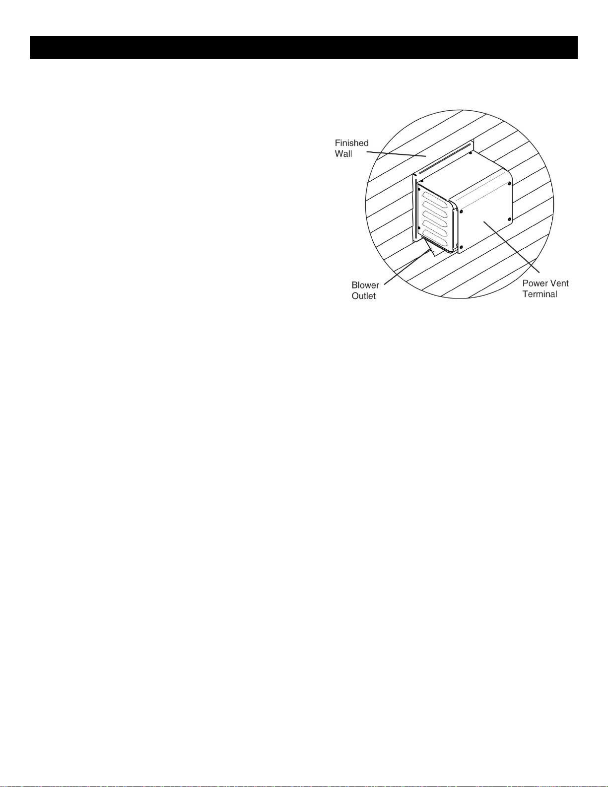
4. Attach the terminal to the outside wall. Ensure that the terminal is the right way up and that only
the outer flanges that are used to secure the terminal to the building are covered by the exterior
wall or siding. (Fig.#4) Note: No other part of the terminal can be recessed into the exterior
wall or siding.
5. Attach the vent adaptor directly to the appliance after the initial 45⁰ elbow before any
horizontal or vertical pipe is added. Tape all exterior seams on the venting system with foil HVAC
tape. Note: The inner pipe does not need to be sealed. (Fig. #5)
6. Connect the high temperature silicone tube to the vacuum pressure tap on the adaptor, secure
with the hose clamp provided and route the tube through the utility access panel back to Power
vent control location. (Fig. #5) Tube may touch unit and be trimmed if required. Connect the
pressure switch tubing to the light grey port on the power vent control. Note: Ensure that there
are no blockages in this tube, as this will cause the control to malfunction. Do not allow tube to
rest on firebox after it is routed.
7. Run the required Simpson Duravent GS / Secure Vent / Selkirk Direct-temp pipe from the adaptor
to the terminal assembly. Assemble as per the vent pipe manufacturer’s instructions.
6
 Loading...