

Page 1
•
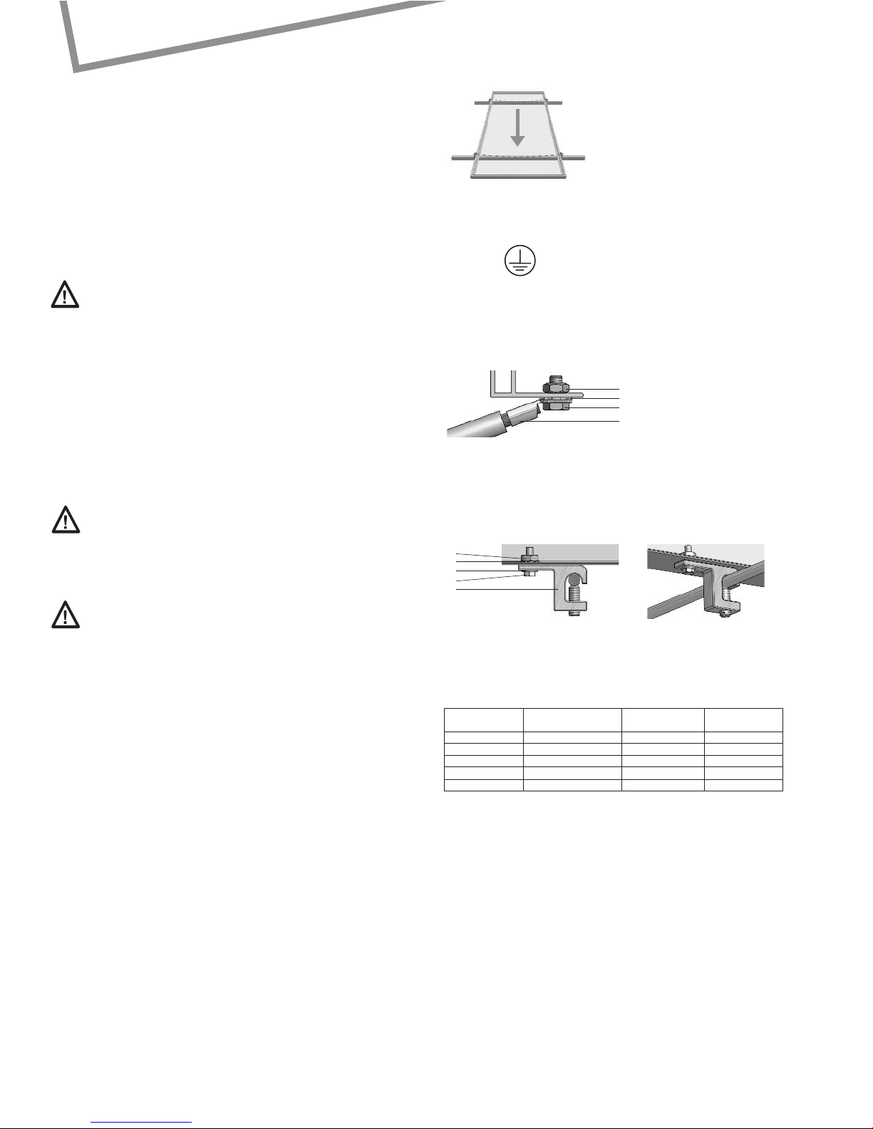
Grounding of the module and frame
Grounding PVmodules isnecessaryto reduceor eliminate shock and fire hazards.
T
he installer of a PV system is responsible for grounding each module frame. It is
r
ecommended to ground each module frame at the provided grounding holes (4 mm
or 5/32 inch diameter, marked with the grounding symbol).
T
he ground connections between modules must be approved by a qualified electrician.
T
he main earth ground must only be connected by a qualified electrician. UL approved
grounding method is mandatory in the USA and Canada.
E
xample A: (Not approvedbyUL)
The modules can be connected at the groundingholes using cables (16 mm
2
or 5 AWG)
with cable lugs.Tocreate the conductive connection (frame is anodized),use a bolt (M 4
o
r 5/32 inch diameter) a serrated washer and a nut.
1
) Cable lug 3) Serrated washer
2) Bolt 4) Nut
E
xample B: (Approvedby UL)
The modules can be connected at the grounding holes using a Lay-in lug and a bolt
with a serrated washer,a washer and a nut.
Drawings:
Ground connection using a cable lug, a bolt, a serrated washer,a washer and a nut.
1) Lay-in lug 3) Serrated washer 5) Nut
2) Bolt 4) Washer
We recommend using the components as listed below.Any UL approved PV grounding
method and components are also acceptable in the US and Canada.
Table:Recommended components
Item Description Manufacturer/ Manufacturer
Distributor Part Number
Grounding Lug Lay-In Lug Ilsco GBL-4
Bolt #6-32,SS McMaster Carr 92314A148
Serrated washer M5, SS McMaster Carr 91120A140
Washer ID 9/64’’,OD 3/8’’,SS McMaster Carr 92141A007
Nut #6-32, SS McMaster Carr 91841A007
• Fire safety
The roof construction and installation may affect the fire safety of a building; improper
installation may contribute to hazards in the event of fire. For roof application, the
modules should be mounted over a fire resistant covering rated for the application.
The module is „non-explosion-protected equipment“. Hence it must not be installed in
the proximity of highly flammable gases and vapors (e.g. filling stations, gas containers,
paint spraying equipment).The module must not be installed near open flames or
flammable materials.
• Suitable environmental conditions
The module is intended for use in temperate climatic conditions.
The modulemust not be subjected to concentrated light.It must not be immersed in water
or constantly exposed to water spray (e.g. from fountains).There is risk of corrosionwith
exposureto salt (it is recommended that modules are installed at least 500 m or 1700 ft
from the sea) and sulfur (sulfur sources, volcanoes).The module may not be exposed to
extremely corrosivechemicals(e.g. emissions from manufacturing plants).
• Suitable installation
Make sure the module meets the technical requirements of the system as a whole. Ensure
that other systemcomponents do not exert damagingmechanical or electrical influences
on the modules. When connected in series, modules must all have the same amperage.
When connected in parallel, the modules must all have the same voltage.The modules
must not be connected together to create a voltage higher than the permitted system
voltage. Modules must not be fitted as overhead glazing or vertical glazing (façade).
Ensure that the mounting system can also withstand the anticipated wind and snow
C
arefully read through these installation instructions before installing,operating or
s
ervicing the photovoltaic (PV) system. Failure to follow these instructions may result in
bodily injury or damage to property. Keep these instructions! Working on a PV system
requires specialized knowledge and must therefore be carried out only by appropriately
q
ualified and authorized personnel. Keep children away!
Warning notices
Danger of death from electric shock!
Solar modules generate electricity as soon as they are exposed to light. The
voltage of a single module is less than 50VDC. When several modules are connected in
s
eries, the summed voltage can be dangerously high. When the modules are connected
in parallel the currents are summed together. Although touch protection is provided
in the form of the fully insulated plug contacts, the following points must be observed
w
hen handling the solar modules to avoid the risk of fire, arcing and fatal electric
s
hock:
• The installation of higher voltage systems should be done by qualified, licensed
professionals.
• Do not insert electrically conducting parts into the plugs or sockets!
•
Do not wear metallic jewelry while performing mechanical or electrical Installation.
• Do not fit solar modules and wiring with wet plugs and sockets! Tools and working
conditions must be dry.
•
Exercise extreme caution when carrying out work on wiring and use the
a
ppropriate safety equipment (insulated tools, insulated gloves, etc.)!
• Do not use damaged modules! Do not dismantle modules! Do not remove any part
or label fitted by the manufacturer! Do not treat the rear of the laminate with paint,
adhesives or mark it using sharp objects!
Danger of death from electric shock!
The inverter can produce dangerous, high voltages, even when not connected:
• Exercise extreme caution when working on wiring and the inverter.
• After switching off the inverter,it is essential to wait for the time interval
specified by the manufacturer before beginning any further work.
This allows the high voltage components time to discharge.
• Be sure carefullyto followthe inverter manufacturer’sinstallation instructions.
Danger of death from arcing!
Modulesgenerate directcurrent (DC) when any amount of light shines on them.
When breaking a connectedstring of modules (e.g. when disconnecting the DC line from
the inverter under load),a lethally strongarc can occur:
• Never remove the solar generator from the inverter while it is still connected to the
main grid!
• Ensure that the cable connections are in perfect condition (no cracking, soiling or other
contamination)!
Unpacking the modules and storage
• Observe the warnings on the packaging!
The utmost care is required when handling the modules.Takecare when unpacking,
transporting, and storing them. Leave modules in packaging until theyare to be installed.
Carrymodules with bothhands.Do not use the connectionsocket as a handle. Do not
stand modules on hard or rough ground. Do not stand modules on their corners. Ensure
modules do not bow. Do not place modules on top of each other.Do not subject to load,
do not stand on them, do not drop.Do not mark or work on them with sharp objects.
Keep all electrical contacts clean and dry.In order to keep a record of your system, we
recommend that you make a note of the serial numbers. If it is necessary to store the
modules temporarily,a dry,ventilated room should be used.
General safety information
Ensure that the module is used for its intended purpose only.Pay attention to the local
ordinances,building standards and accident-prevention regulations during installation.
The safety information for other system components must also be followed.
Installation
When installing the modules, please pay attention to:
• Safety during installation
Do not carry out installation work when there are strong winds. Secure yourself and
other workers to avoid falling. Secure work materials to prevent articles from falling.
Create a work zone to avoid accidents with other people.
• Keeping within the maximum permitted load
Make sure the support structure adheres to maximum permissible load requirements as
prescribed by local ordinances, particularly in regions of high snow accumulations and
high wind velocities. Take notice to possible bowing of the modules under high loads.
Avoid installing fasteners, cable ties, etc. between the module backside and support
structure (i.e. on mounting rails) as any sharp edges can damage module.
Quick Guide for Users
SolarWorld® solar modules
Last revised: February 2008
D
rawing:
B
owing of the module under
high mechanical front loads.
D
rawing:
Ground connection using
a cable lug, bolt, serrated
washer and a nut
See: www.ilsco.com;www.mcmaster.com
4
3
2
1
5
3
4
2
1
Drawing:
G
rounding symbol
Page 2
SolarWorld AG
Kurt-Schumacher-Straße 12-14
53113 Bonn
Germany
Telefon: +49 - 228 - 55920 - 0
Telefax: +49 - 228 - 55920 - 99
[email protected]
www.solarworld.de
SolarWorld Ibérica, S.L.
C/La Granja 15, Bloque B-1°B
28108 Alcobendas,Madrid
SolarWorld California Inc.
4650 Adohr Lane
Camarillo,CA 93012
USA
Tel.: +1 - 800 - 947 - 6527
Fax:+1 - 805 - 388 - 6395
[email protected]
www.solarworld-usa.com
Underwriters Laboratories Information (U.S. and Canada)
•
The solar module electrical characteristics are within +/-10% of the module label
i
ndicated values of Isc ,Voc,and Pmpp under Standard Test Conditions (irradiance of
100 mW/cm
2
, AM 1.5 spectrum, and a cell temperature of 25°C/77°F)
• Under normal conditions, a photovoltaic module is likely to experience conditions that
p
roduce more current and/or voltage than reported at standard test conditions.
A
ccordingly, the values of Isc and Voc marked on this module should be multiplied by a
factor of 1.25 when determining component voltage ratings, conductor capacities, fuse
s
izes,and size of controls connected to the PV output.
•
Refer to section 690-8 of the National Electric Code (NEC) for an additional multiplying
factor of 125% (80% de-rating) which may be applicable
• Over-current protection shall be in accordance with the requirements of Article 240 of
t
he NEC
•
Conductor recommendations:8-14 AWG (1.5-10 mm
2
)
USE-2 (nonconduit)/ THWN-2
(conduit ), 90°C wet rated
•
Cable conduits should be used in locations where the wiring is accessible to children
o
r small animals
• Modificationor tampering of diodes by unqualified personnel is not permitted. Please
consulta SolarWorld Service Center foradditionalinformation regarding diode
r
eplacement/repair.
Maintenance and cleaning
G
iven a sufficient tilt (at least 15°), it is generally not necessary to clean the modules
(rainfall will have a self-cleaning effect). In case of heavy soiling, we recommend cleaning
the modules using plenty of water (from a hose) without any cleaning agents and using
a
gentlecleaningimplement(a sponge). Dirt must never be scraped or rubbed away when
d
ry,as this may cause micro-scratches.
We recommend that the system be inspected at regular intervals to ensure:
1. All mounting points are tight and secure and free of corrosion.
2
. All cable connections are secure, tight, clean and free of corrosion.
3. Cables are not damaged in any way.
4. The conductivity of module frame to earth ground.
Disclaimer of liability
Sincecompliancewith this guide and the conditions and methods of installation,operation,
use and maintenance of the modules are not checked or monitored by SolarWorldAG,
SolarWorld AG accepts no liability for damage arising through improper use or incorrect
installation, operation, use or maintenance.This does not apply to damages due to a
module fault, in cases of loss of life, bodily injury or damage to health or in the event of a
grossly negligent breach of obligations on the part of SolarWorldAG and/orin the event of
an intentionalor grossly negligentbreachof obligations by a legalrepresentativeor vicarious
agent.
Furthermore,liability for infringements of patentlaw or of otherthirdpartyrightsarising
from the use of the modules is excluded unless we are automatically liable by law.
loads.There are openingsat the base of the moduleframe to allow waterfrom precipitation
to drain. Ensure that these openings are not blocked nor partially blocked by the module
i
nstallation method.
• Optimum orientation and tilt
T
o obtain maximum yield from the system, we recommend that you determine the best
d
irection and tilt angle for the modules. Conditions for generating electricity are
considered ideal when the sun’s rays strike the module perpendicular to its surface. To
avoid
p
erformance drops in series circuits, ensure that all modules have the same orientation
a
nd tilt.
•
Avoidance of shading
E
ven partial shading will cause a yield reduction. A module is “shade free“ when the entire
surface is shade free all year round and, even on the most unfavorable days of the year,
receives unobstructed sunlight.
• Adequate ventilation
Ventilationof the module backside is necessary to avoid the build-up of heat that can
r
educe performance.
Mounting
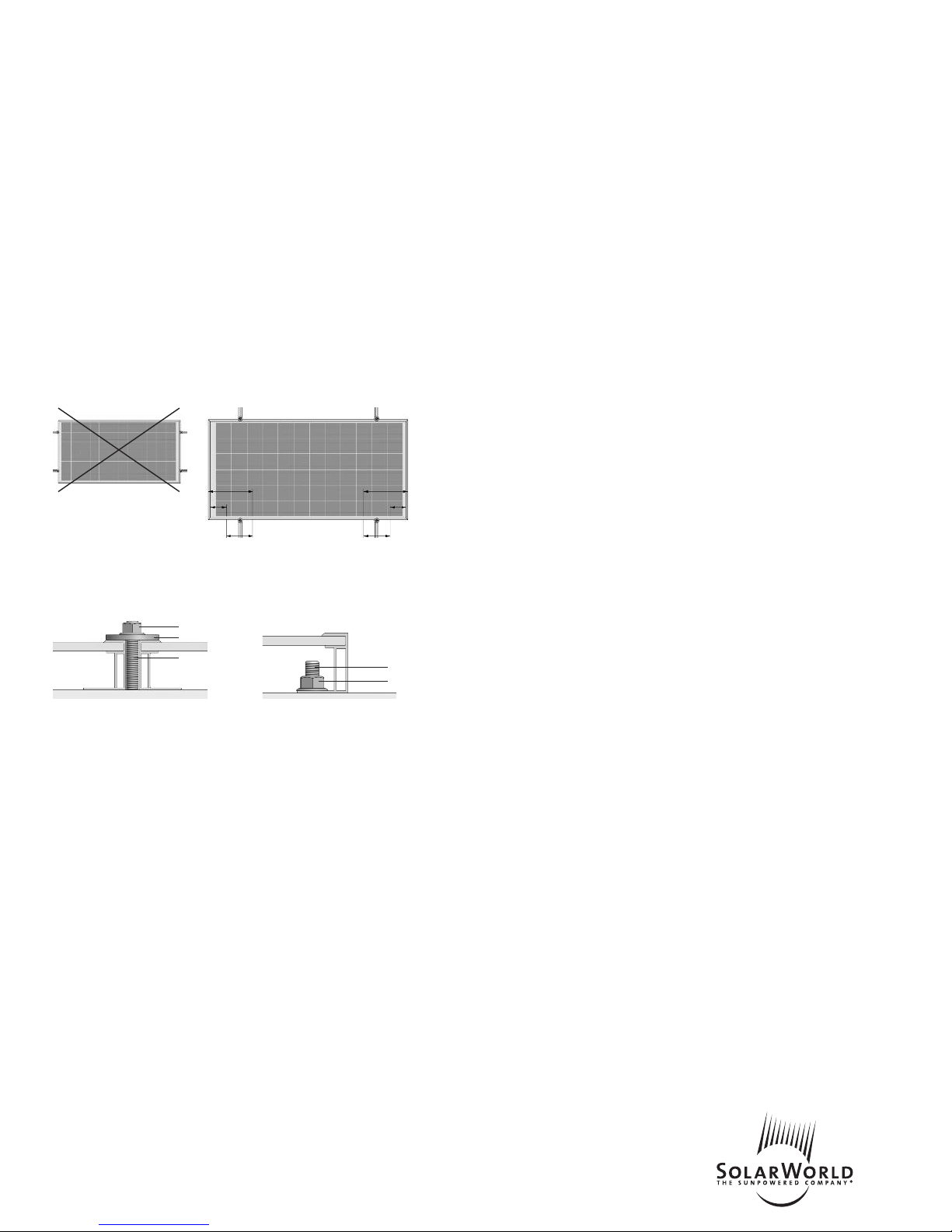
E
ach module must be securely fastened at a minimum of 4 points. The frame has been
stress tested for mounting by the long sides. The module should not be secured by its
short sides.
PV modules can be mounted to the substructure by clamping on (ExampleA) at the front
side or by screwing (Example B) at the back side.
Example A: Clamping Example B: Bolting
The clamping area (Example A) of the washer must cover at least 135 mm
2
or 0.21 in2.
A torque wrench must be used for assembly. In the examples shown, the tightening
torque(using stainlesssteel M8 or 5/16 inch bolts) must be 16 Nm or 11.8 ft-lbf.Use the
existing holes for securing the module; do not drill any additional holes (doing so would
void the warranty). Use appropriate corrosion-proof fastening materials.
Wiring
The module is provided from the factory with pre-connectorized cables.
Under no circumstances should the junction box be opened.
For the wiring, pay attention to:
• Correct wiring scheme
In order to decrease voltage caused by indirect lightning strikes, all connecting cables
should be as short as possible. Check that the wiring is correct before commissioning the
system. If the measured open circuit voltage differs from the specifications, then there is
a wiring fault. Ensure that the polarity is correct.
• Correct plug connections
Make connections only in dry conditions. Ensure that connections are secure and tight.
• Use of suitable materials
Use special solar cable and suitable connectors only. Ensure that they are in perfect
electrical and mechanical condition. Use only single wire cables. Select a suitable
conductor diameter to minimize voltage drop.
• Cable protection
Secure the cables to the mounting system using UV-resistant cable ties. Protect exposed
cables from damage using suitable precautions (e.g. running them through plastic
conduit). Avoid direct exposure to sunlight.
SolarWorld Asia Pacific Pte. Ltd.
72 Bendemeer Road
#07-01, Luzerne
Singapore 339941
Singapore
Tel.: +65 - 6842 - 3886
Fax:+65 - 6842 - 3887
[email protected]
www.solarworld.sg
SolarWorld Africa Pty. Ltd.
20
th
Floor
1 Thibault Square
Cape Town,8001
South Africa
Tel.: +27 - 21 - 421 - 8001
Fax:+27 - 21 - 421 - 8002
[email protected]
www.solarworld-africa.co.za
1) Stainless steel serrated lock nut
2) Stainless steel washer
3) Stainless steel M8 (5/16 inch) T-head bolt
1
2
3
1
3
1/4 module length
mounting area
mounting area
1/4 module length
1/8 module length
1/8 module length
do not mount
on the short side
 Loading...