

SolarMax TS-SV
330TS-SV / 360TS-SV
Bedienungsanleitung ■ Operating manual ■ Notice d’emploi
Documentación del dispositivo
■ Istruzioni per l’uso

49
Contents
1 About this operating manual 51
1.1 Scope 51
1.2 Target group 51
1.3 Where to keep this manual 51
1.4 Symbols used in this manual 51
2 Safety instructions 52
3 Description 53
3.2 Operating elements 53
3.2.1 Inverter 54
3.2.2 Master Control Unit (MCU) 55
4 Operation 56
4.1 How the main switch works 56
4.2 How the DC and AC power switches work 56
4.3 Switching on the inverter 57
4.4 Switching off the inverter 58
4.5 Operating the graphics display 59
4.5.1 Menu button symbols 59
4.5.2 Menu structure 60
5 Data communication 72
5.1 Configuration of the data communications interfaces 73
6 Options 74
6.1 MaxControl 74
6.1.1 Scope of services 74
6.1.2 Duration 74
6.2 Accessory components 74
7 Operating status 75
7.1 Status messages and status LED 75
7.2 Booting 76
7.3 Mains operation 76
7.4 Communications activity 76

50
en
8 Troubleshooting 77
8.1 SolarMax Service Center 78
8.2 Diagnosis & corrective steps 78
8.2.1 General troubleshooting 78
8.2.2 Warnings 78
8.2.3 Malfunctions 80
8.2.4 Error 81
8.2.5 Blockages 81
9 Maintenance 82
9.1 Inspections by the plant operator 82
9.2 Maintenance by a qualified electrician 82
9.3 Testing grid monitoring 83
10 Disposal 86
51
1 About this operating manual
1.1 Scope
This operating manual describes the operation, troubleshooting, and maintenance processes for the inverters SM330TS-SV, SM360TS-SV (TS-SV inverter) and their control
unit TS-SV Master Control Unit (MCU).
1.2 Target group
This operating manual is written for the operator of the PV system and the quali ed
electrician.
1.3 Where to keep this manual
The system operator must ensure that this operating manual is available to those responsible for the system at all times. If this original document is lost, an up-to-date version of
the operating manual can be downloaded from our website (www.solarmax.com).
1.4 Symbols used in this manual
From time to time you will see the following symbols when reading this operating manual:
DANGER
This symbol indicates that ignoring this instruction can lead directly to serious
injury or death.
CAUTION
This symbol indicates that ignoring this instruction can lead to damage to your
inverter or your PV power plant.
NOTE
This symbol indicates information which is especially important for operating
the inverter.

52
en
2 Safety instructions
DANGER
■ In daylight the PV generator supplies the inverter with a dangerously high DC
voltage.
■ SolarMax inverters and accessories may only be installed or opened by quali ed
electricians who have completely read and understood this instruction manual in
advance.
■ Only quali ed electricians who have already completely read and understood this
instruction manual in advance may install and open SolarMax inverters.
■ Ignoring the installation and safety instructions shall cancel any and all warranty
and liability claims.
■ Touching live parts is life-threatening.
■ The inverters and accessories must not be opened at any time during operation.
■ Before the inverter or the MCU is opened, the DC and AC feed lines must be dis-
connected according to the instructions and secured against being reconnected
accidentally.
■ After disconnecting the inverter wait at least 5 minutes before opening the device
to permit internal capacitors to discharge.

53
3 Description
All SolarMax inverters work completely automatically. The DC and AC power switches
(Q4-Q6 and Q1-Q3) as well as the main switch (Q7) are always on during normal operation. The inverter starts when there is enough input power and continues to operate until
the available input power from the PV generator drops below the necessary minimum.
The inverter is operated using the external master control unit (MCU). The MCU controls
the connected inverters and is also the communications and user interface.
3.2 Operating elements
The following section describes the operating elements of the TS-SV inverter and the
master control unit (MCU).

54
en
3.2.1 Inverter
Legend:
1
AC power switch Q1
4
DC power switch Q4
2
AC power switch Q2
5
DC power switch Q5
3
AC power switch Q3
6
DC power switch Q6
1 42 53 6

55
3.2.2 Master Control Unit (MCU)
Legend:
1
Main switch Q7
4
Status LED
2
Graphics display
5
Lock
3
Push-buttons
1
5
2
3
4
56
en
4 Operation
The inverter is operated using the external MCU. The MCU allows all the connected inverters to be operated simultaneously, only the DC and AC power switches must be operated
directly on the respective inverter.
For all other functions described below the MCU is the shared interface for all the connected inverters.
4.1 How the main switch works
When you switch off the main switch Q7, turning it to the OFF position, the inverter opens
the contacts of the AC protections K1, K2 and K3. This disconnects the inverter from the
mains.
DANGER
If you switch the main switch Q7 to the OFF position, the inverter’s components are
still live! This includes the 3 power units and the lters on the input end!
4.2 How the DC and AC power switches work
The DC power switches Q4, Q5 and Q6 are used to connect or disconnect the direct
current of the PV plant to the inverter. The AC power switches Q1, Q2 and Q3 connect or
disconnect the inverter to or from the mains. The DC as well as the AC power switches
are equipped with thermomagnetic overcurrent fuses.
DANGER
Even when the DC and AC power switches are switched off, the connections for the DC
and AC feed lines in the inverter are still live!

57
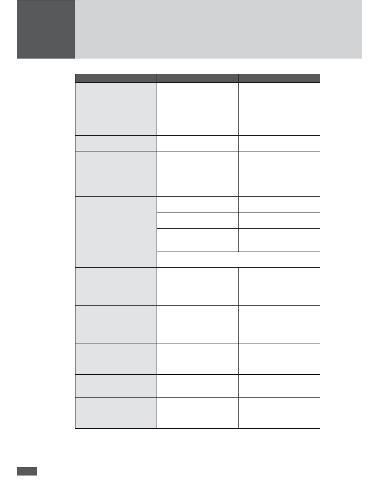
4.3 Switching on the inverter
Procedure
Action Reaction
1. Switch off main switch Q7
(to “OFF” position)
2. Switch on DC power switch Q4, Q5 & Q6
(to “ON” position)
The graphics display is activated after a
maximum of 20 seconds (if there is enough
sunlight).
3. Switch on AC power switch Q1, Q2 & Q3
(to “ON” position)
4. Switch on main switch Q7
(to “ON” position)
After several seconds the Overview menu is
displayed. The message “Startup....” appears
in the “Status” line. The status LED blinks
green.
When the connected inverters have been
started up and are feeding power into the
mains, indicates the device status “Mains
operation”. The status LED glows green.
NOTE
■ When the inverters are commissioned the “Initial Setup” menu appears rst,
during subsequent start-ups the “Overview” menu; see the installation manual.
■ If several inverters are connected to one MCU steps 2 and 3 must be performed
for each inverter before the main switch Q7 switches on the whole system (step 3).

58
en
4.4 Switching off the inverter
DANGER
■ Even when the inverter is switched off, the connections for the DC and AC feed
lines in the inverter remain live!
■ Before the inverter or the MCU is opened, the DC and AC feed lines must be dis-
connected according to the instructions and secured against being reconnected
accidentally.
■ After disconnecting the inverter wait at least 5 minutes before opening the device
to permit internal capacitors to discharge.
Procedure
Action Reaction
1. Switch off main switch Q7
(to “OFF” position)
Message on the graphics display is: “Main
switch off”. The device disconnects from the
mains.
2. Switch off AC power switch Q1, Q2 & Q3
(to “OFF” position)
3. Switch off DC power switch Q4, Q5 & Q6
(to “OFF” position)
After a short time the graphics display of the
MCU is shut down.
NOTE
Steps 2 and 3 must be repeated for each inverter connected to the MCU.

59
4.5 Operating the graphics display
The graphics display on the front of the MCU shows the system dimensions, status information and the malfunction messages of the connected inverters. The display allows you
to learn the current device status, access the integrated data logger and enter various
system settings. Navigate the various menus using the three push-buttons under the
display.
Since the MCU is supplied with power both from the DC end and the AC end, it is also
possible to use the MCU functions at night or when the DC end is shut down. However,
the inverters connected to the MCU only deliver data and measured values if the inverters
are in operation (when there is enough power from the DC end).
To the left of the graphics display there is a status LED indicating the device status, see
7.1 “Status messages and status LED”.
4.5.1 Menu button symbols
With the help of the symbols shown here you can navigate the various menus and functions visible in the display. The current button function changes from one menu to the
next, corresponding to the symbol appearing directly over the button:
Symbol Function
Scroll up, increase number or next element
Scroll down, or previous element
Back to higher level menu
Select next number
Display selected submenu or con rm changes
Launch edit mode for selection
Abort

60
en
4.5.2 Menu structure

61
4.5.2.1 Main menu
The main menu is the starting point for all the submenus and displays, see 4.5.2 “Menu
structure”. Use the arrow keys
and to select a menu. Click to con rm your
selection.
4.5.2.2 Overview
If none of the three buttons is pushed for 120 seconds, the display returns automatically
to the Overview menu which shows the three most important values as well as the current
operating status of the system (all the inverters connected to the MCU).
Operating parameters Description
17.02.2010 (example) Current date
11:44:35 (example) System time
Pac Momentary effective output
Today Total energy fed into the mains on the current date and as of the
momentary time.
Total Total energy fed into the mains since the inverter’s
commissioning.
Status For status messages and warnings of the system, see 7 “Operat-
ing status” and 8.2.2 “Warnings”.
4.5.2.3 Measured values

62
en
The “Measured values” menu allows the display of currently measured values in relation
to the system or the power unit selected.
NOTE
■ The number of power units listed in the “Measured values” menu depends on the
number of inverters connected to the MCU.
■ Three power units are displayed per inverter.
■ The numbering of the power units follows the addresses allocated to the power
units at the time of the installation (see Installation Manual).
Use the button to highlight a category. Select a category by pressing the button.
In each case only four measured values are displayed at the same time.
Use the arrow buttons and to navigate the measured values. Press the left button
to return to the Main menu.
63
The following measured values can be accessed for the system:
Measured value Description
Vdc DC Input voltage (only in single MPPT operation)
Idc DC Input current (only in single MPPT operation)
Vac (L1L2, L2L3, L3L1) Mains voltage (Phase to Phase)
Iac (L1, L2, L3) AC Input current (per Phase)
Pac Active output power
Q Reactive power (+: overexcited / −: underexcited)
S Apparent output power
Cosφ
Power factor (OEX: overexcited / UEX: underexcited)
Frequency Mains frequency
Temperature Highest currently measured temperature in the power unit
The following measured values are available for the relevant power unit:
Measured value/Status Description
Vdc DC Input voltage
Pdc Input power at the power unit
Temperature Highest currently measured temperature in the power unit
Fan Operating condition of fans
Status Operating status of the power unit (On/Off/Error)
Measured values only to be displayed with MaxTalk (menu: device/measured values):
Measured value Description
Prel Relative output (Prel = (Pac/Pinst tot) × 100%)
Vsym Voltage of the PV generator in comparison with the earthing
potential(DC+ and DC- against earth)
Vsym AC Effective value of the AC voltage share of the DC symmetry
voltage
Ief Earth fault current
NOTE
Remember that the MCU measured values must not be used for billing purposes or
calculating ef ciency. Only the measured values of a calibrated electricity meter are
the basis for billing purposes.
64
en
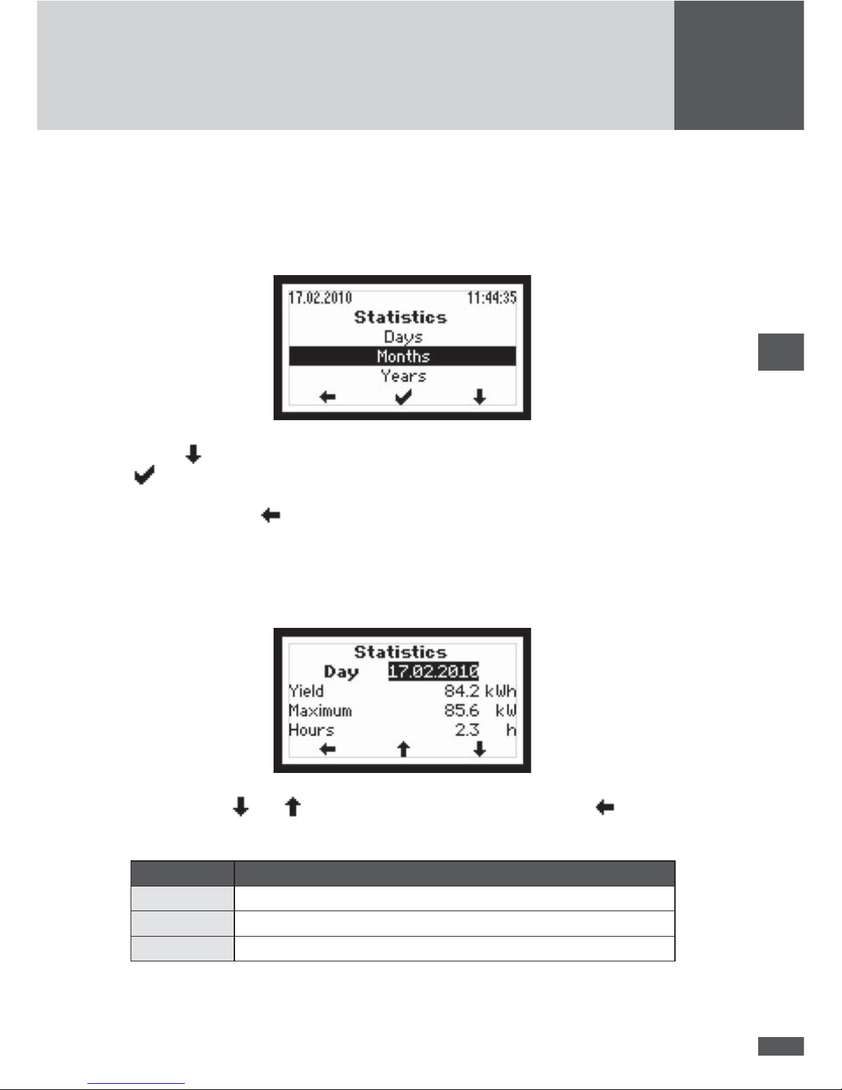
4.5.2.4 Statistics
In the Statistics menu you can access the MCU’s internal data logger. The accessible
statistics are for the most recent 31 days, 12 months or 10 years. The displayed statistical
values each refer to the system as a whole.
Use the button to highlight a statistic category. Select a category by pressing the
button.
Press the left button
to return to the Main menu.
Daily statistics
This menu provides access to the data from the most recent 31 days.
Use the buttons and to select a daily statistic. Press the left button to return
to the Statistics menu.
Parameter Description (refers to the day displayed)
Yield Total amount energy fed into the mains
Maximum Peak value of the output fed into the mains
Hours Total operating hours (in device status “mains operation”)
65
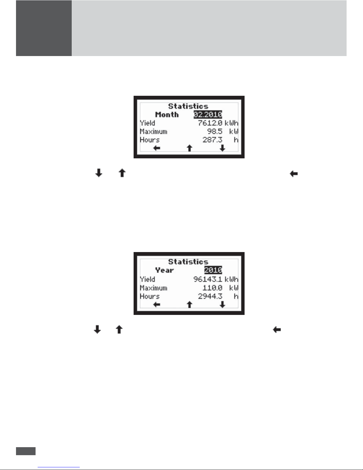
Monthly statistics
This menu provides access to the data from the most recent 12 months.
Use the and buttons to select a monthly statistic. Press the left button to
return to the Statistics menu.
The displayed values correspond to those in the daily statistics; but the values refer to
the month displayed.
Yearly statistics
This menu provides access to the data from the most recent 10 years.
Use the and buttons to select a yearly statistic. Press the left button to return
to the Statistics menu.
The displayed values correspond to those in the daily statistics; but the values refer to
the year displayed.
66
en
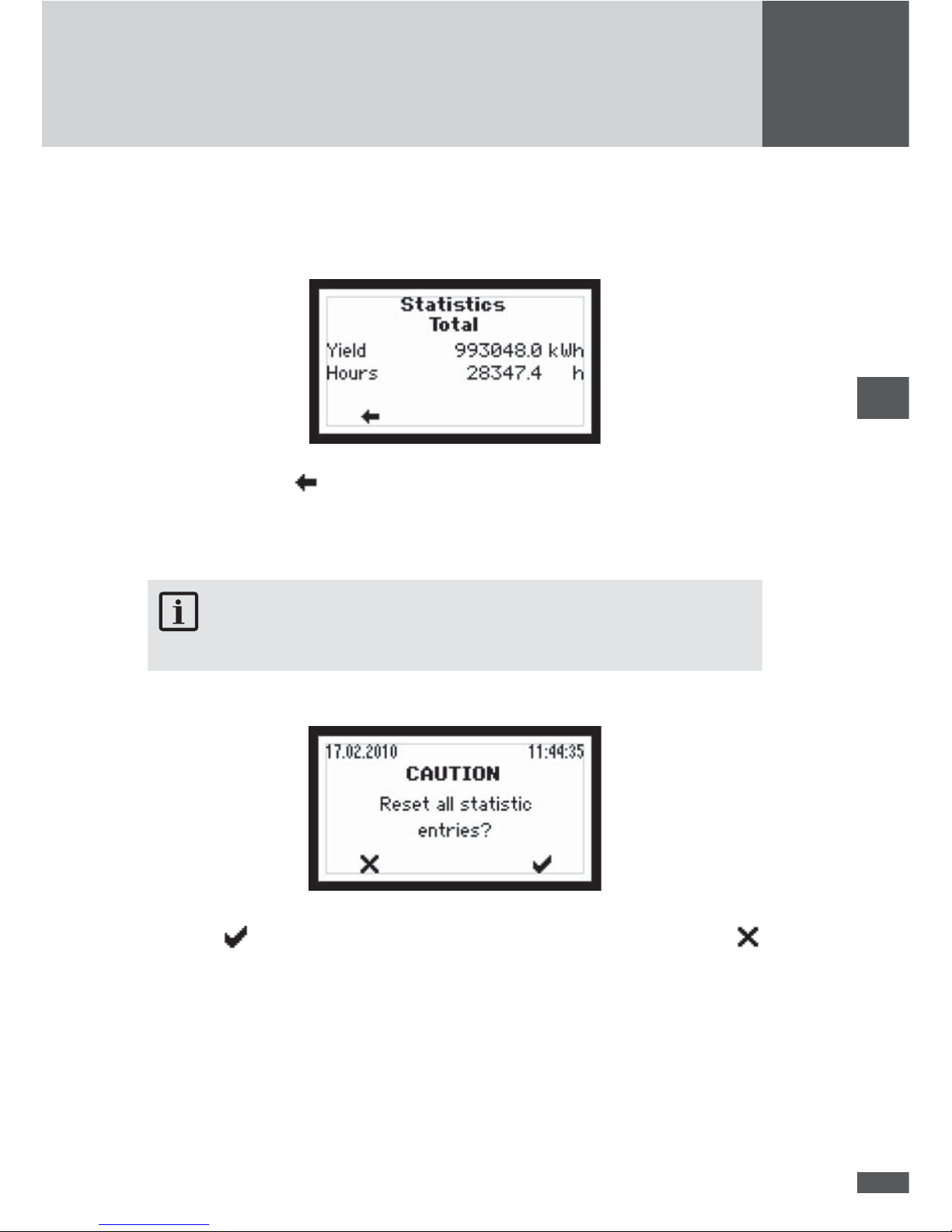
Total
This menu lists the total yield and the total number of operating hours of the inverter or
the system since it was commissioned.
Press the left button to return to the Statistics menu.
Reset
In this menu you can delete all the entries in the Statistics menu.
NOTE
Once deleted these data are irretrievably lost!
Press the button to con rm the deletion of all the statistics entries. Use the
button to enter the Statistics menu without deleting the statistics entries.
67
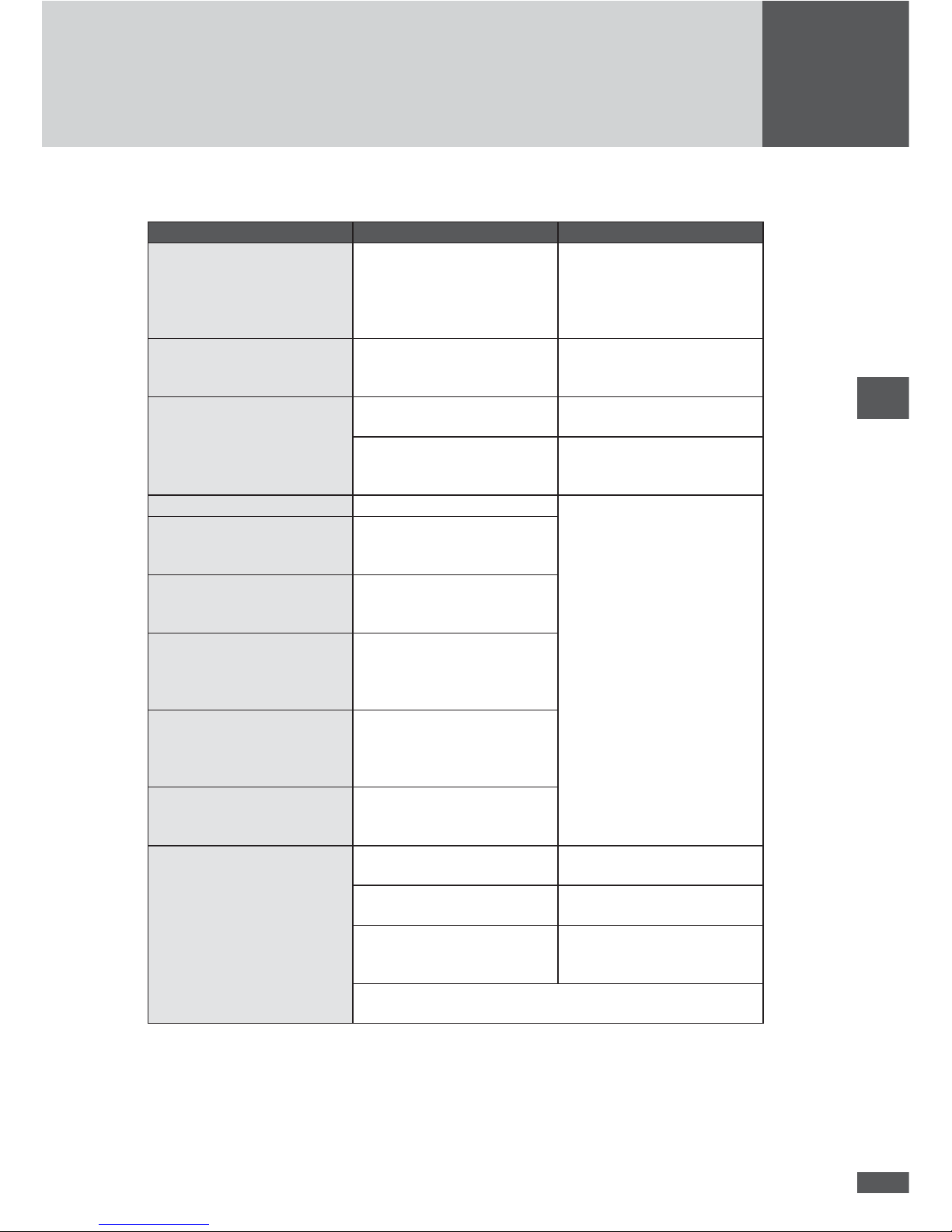
4.5.2.5 Con guration
The “Con guration” menu contains the inverter’s available operating parameters and advanced functions. The settings displayed for the limit values and the functions depend on
the country selected during initial start-up.
NOTE
MaxTalk 2 Pro, the extension to the standard MaxTalk 2 software, allows author-ised
skilled workers to individually adjust the operating parameters. The required “TS series/TS-SV parameter con guration using MaxTalk 2 Pro” instruction manual can be
found on our website www.solarmax.com (Downloads area). You can request MaxTalk
2 Pro from the SolarMax service centre. The contact details can be found overleaf.
Parameter Description Unit
Country Country settings selected during initial start-up f nominal Mains nominal frequency Hz
Vac nominal Mains nominal voltage V
Vac min 1 Minimum admissible mains voltage ( rst limit) V
t Vac min 1 Release time for minimum admissible mains voltage ms
Vac max 1 Maximum admissible mains voltage ( rst limit) V
t Vac max 1 Release time for maximum admissible mains voltage ms
Vac min 2 Minimum admissible mains voltage (second limit) V
t Vac min 2 Release time for minimum admissible mains voltage ms
Vac max 2 Maximum admissible mains voltage (second limit) V
t Vac max 2 Release time for maximum admissible mains voltage ms
Vac 10 min max Maximum admissible average value of the mains voltage
over the last 10 minutes
V
f min 1 Minimum admissible mains frequency ( rst limit) Hz
t f min 1 Release time for minimum admissible mains frequency ms
f max 1 Maximum admissible mains frequency ( rst limit) Hz
t f max 1 Release time for maximum admissible mains frequency ms
f min 2 Minimum admissible mains frequency (second limit) Hz
t f min 2 Release time for minimum admissible mains frequency ms
f max 2 Maximum admissible mains frequency (second limit) Hz
t f max 2 Release time for maximum admissible mains frequency ms
Iac max Maximum admissible mains current (per shift) A
Pac max Maximum effective power to be fed W
S max Maximum apparent power to be fed. VA
Island Detection Immediate grid disconnection when island operation
detected
-
OV Detection Immediate grid disconnection with transients to Vac -
68
en
Parameter Description Unit
Restart delay Delay time before mains reconnection upon previous
failure-related mains disconnection.
s
Pac Progression Maximum increase of the effective power during mains
reconnection upon previous failure-related mains
disconnection.
%/Minute
Soft Start Maximum increase of the effective power at mains con-
nection. This gradient, if activated, is always effective,
as opposed to Pac Progression (even during restart in the
morning).
W/s
Mains check Additional monitoring before connecting to the mains -
- Vac MC max Maximum admissible mains voltage at mains check V
- Vac MC min Minimum admissible mains voltage at mains check V
- f MC max Maximum admissible mains frequency at mains check Hz
- f MC min Minimum admissible mains frequency at mains check Hz
- t MC monitoring Duration of mains check s
P(f)-Mode Frequency-dependent power reduction (1/2/3/Off)
- Reduction Reduction of effective power Pac in P(f) mode %/Hz
- f start Starting frequency of the P (f) mode Hz
- f stop Stop frequency of the P(f) mode Hz
- MC f max Maximum admissible mains frequency at mains check in
P(f) mode
Hz
- MC f min Minimum admissible mains frequency at mains check in
P(f) mode
Hz
- MC time Duration of mains check in P(f) mode W/s
- Re-increase Maximum increase to the maximum effective power Pac
max in P(f) mode.
%/Minute
Q-Mode
Reactive power mode (Off/cosφ/cosφ(Pac)/Q/Q(Vac))
-
FRT Fault ride through function for dynamic grid support -
- K factor Reactive current static factor for voltage support with reactive current during mains drops
-
RC mode Remote control by solar plant controller
(Off/On/Guarded)
-
- Timeout Maximum admissible time without control commands at
remote control by solar plant controller.
s
69
4.5.2.6 Settings
This menu can be used to set different communication parameters and monitoring functions.
All settings can also be implemented with MaxTalk (menu: Devices/Settings).
NOTE
The term “system” comprises all TS-SV inverters connected to the MCU.
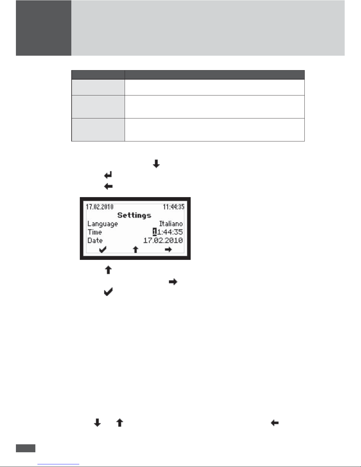
Parameter Description
Language Selection of the display language (German, English, French, Italian, or
Spanish). The display language can be selected independently of the
selected speci c country settings.
Time Setting the internal clock (RTC)
Date Setting the displayed date
Device address De nition of a device address between 1 and 249. For details see 5.1
“Con guration of the data communication interfaces”.
IP
Con guration of the Ethernet interface. For details see 5.1 “Con guration
of the data communication interfaces”.
Netmask
TCP Port
Status relay delay Setting the switching delay of the status signalling contact (status relay)
Pinst tot Rated output power of the PV generator (entry only possible in MaxTalk).
“Pinst tot” is used to calculate PreI (see 4.5.2.3 “Measured values”) and
the target yield (display in the MaxWeb portal).
Status relay
The functions of the status relay or the status signalling contact can be adjusted. There
are three different functional settings.
Setting Description
Off The status signalling contact is always open.
Grid When the system starts grid operation, the status signalling contact of
the MCU will close immediately and remains closed as long as the system
feeds in. When the system no longer feeds into the grid, the status signal-
ling contact will open upon expiration of the adjustable delay time.
Error If a warning, malfunction or device error occurs with the system, the
status signalling contact of the MCU will close after the adjustable delay
time has expired (the events are listed in 8.2 “Diagnosis & corrective
steps”). The status signalling contact will immediately open if the error is
no longer present.
The monitoring electronics are supplied by the PV generator, in other words during the
night and when the DC side is switched off, the status signalling contact is open.
70
en
Fuse failure PAS
The equipotential bonding kit (PAS) is an accessory component and serves for earthing
the PV generator. The behaviour of the system during fuse failure on the equipotential
bonding kit can be controlled. For this, the function “Fuse failure PAS” offers three different settings:
Setting Description
Off Monitoring the fuse in the equipotential bonding kit is switched off. Select
this setting for test purposes only.
Warning The warning message “Fuse failure PAS” is displayed. The system will
continue to feed into the mains. The status signalling contact of the MCU
will be closed (factory setting).
Error The malfunction message “Fuse failure PAS” is displayed. The system will
disconnect from the mains immediately. The status signalling contact of
the MCU will be closed.
NOTE
Read the hazard warnings and instructions in the device documentation on the equipotential bonding kit before replacing the fuse.
Vsym Monitor (MaxTalk: Usym DC Monitor)
The DC insulation monitoring (Vsym Monitor) checks the symmetry of the voltage of the
PV generator regarding the earthing potential before mains activation. If the voltages
(DC+ and DC- against earth) are not symmetrical or if there is a short-circuit against
earth, this will be detected by the MCU. Three settings are possible:
Setting Description
Off The DC insulation monitoring is switched off.
Switching off DC insulation monitoring is only required when using the
equipotential bonding kit.
Warning The warning message “Insulation failure DC” is displayed. The system will
continue to feed into the mains. The status signalling contact of the MCU
will be closed (factory setting).
Error The malfunction message “Insulation failure DC” is displayed. The system
will disconnect from the mains immediately. The status signalling contact
of the MCU will be closed.
Vsym AC Monitor
The monitoring of the AC share on the DC side (Vsym AC Monitor) detects too high parasitic oscillations and capacitive leakage currents on the PV generator. Furthermore, insulation failures between the transformer and the system can be detected. Three settings
are possible:
71
Setting Description
Off The AC insulation monitoring is switched off. Select this setting for test
purposes only.
Warning The warning message “Insulation failure DC” (MaxTalk: “DC insulation
failure (AC)”) is displayed. The system will continue to feed into the mains.
The status signalling contact of the MCU will be closed (factory setting).
Error The malfunction message “Insulation failure DC” (MaxTalk: “DC insulation
failure (AC)”) is displayed. The system will disconnect from the mains im-
mediately. The status signalling contact of the MCU will be closed.
Implementing the settings
1. Select parameter using the
button; e.g. time.
2. Push the
button to switch into the editing mode.
3. Push the
button to get to the desired position of the parameter:
4. Push the button to increase the gure.
5. Select the next position using the
button or
6. Push the
button to con rm the value and exit the editing mode.
4.5.2.7 Information
This menu contains the following information:
■ Device type
■ Series number
■ Firmware version
■ Status message and two-digit number code (if a device error occurs)
■ Warning (alternating display if several warnings are active at the same time)
■ Date of commissioning
■ Accumulated operating hours
■ Date and Time
Use the
and keys to move through the menu. Press the left button to return
to the Main menu.
72
en
5 Data communication
For PV power plants equipped with SolarMax inverters Sputnik Engineering provides the
MaxComm communications platform. This provides many ways of recording data and
monitoring your PV power plant. Below is an overview of the current products.
NOTE
You can nd detailed information on our website at www.solarmax.com.
MaxTalk 2.0: For occasional communication and the configuration of the inverters
If you only need to access your system data or modify your system’s settings occasionally, the MaxTalk PC software is ideal for you. MaxTalk can be downloaded at no charge
from our website.
MaxWeb xp: The gateway to Internet-supported communication
MaxWeb xp is a data logger, monitoring unit and web server in one. For all those who want
to have their PV power plant monitored and checked reliably and professionally MaxWeb
xp is the ideal solution.You can access your PV power plant from any internet-connected
PC to check current measured values and yields or to modify your system settings. The
data logger records operating parameters, yield values and events and communicates
them automatically to the SolarMax web portal.
If there is a malfunction, MaxWeb xp sends out alarm messages by e-mail or SMS.
MaxWeb Portal: For accessible power plant data at any time
The MaxWeb Portal is the ideal complement to the MaxWeb xp data logger. When you use
MaxWeb Portal you can access the data of your PV power plant from anywhere on the
Internet. The MaxWeb Portal provides a wide variety of graphic and chart display options
for the evaluation of your PV power plant’s operating parameters.

73
5.1 Con guration of the data communications interfaces
In order to use the RS485 and Ethernet communications interfaces, you must enter the
following settings in the “Settings“ display menu:
Device address
If you connect several systems and/or MCUs to become one network, you will need a
separate address for each system.
NOTE
■ You can assign addresses between 1 and 249. Please make a point to remember
to assign a unique address to each system in the network!
■ Start the address numbering with the lowest numbers possible (if possible with
001).
When connecting to a LAN network, the following settings are required in addition to the
device address:
IP
If you want to access your system from a local area network (LAN), enter here an unassigned IP address from your LAN.
Netmask
Please enter here the pertinent sub-netmask for your IP address.
TCP port
Enter your TCP port selection for communications with the system. Remember that the
TCP port must be greater than 1023 since this range is reserved for prede ned applications (referred to as “well known services”).
NOTE
You will nd more details about data communications in the technical information
“MaxComm network”. This document can be downloaded from our website at: www.
solarmax.com; downloads/data communication/MaxComm.

74
en
6 Options
6.1 MaxControl
6.1.1 Scope of services
MaxControl is a service package for your solar system with SolarMax central inverters.
It is based on the MaxComm communications system and includes:
■ Automatic yield control including monthly analysis
■ Forwarding of malfunction reports to the client via email and/or SMS
■ Troubleshooting and on-site service by Sputnik Engineering
■ Warranted availability of 97 % annually
■ Yield shortfall payments if availability < 97 %
■ Free inverter repair
6.1.2 Duration
■ Two years and three months from the date of shipment.
■ When the period is up the warranty can be renewed for one more year.
Remember that a MaxControl service package can only be agreed at the time the
SolarMax central inverter is purchased and afterwards it is no longer possible.
The agreement is automatically renewed if you do not cancel it in writing at least one
month before the end of the calendar year. The agreement can be renewed no more than
eighteen times. The total term of the package is thus 25 years and three months.
NOTE
You can obtain further details about MaxControl directly from Sputnik Engineering.
6.2 Accessory components
Here is a list of other available accessory components.
MaxConnect plus
Generator connection box with integrated string monitor
MaxMeteo
Unit which records irradiation data and cell temperature of PV modules

75
MaxCount
Unit which records meter gures with S0-interface
MaxDisplay
Interface for large display to visualise PV power plant data
Potential equalization set
The potential equalization set enables the earthing of the PV generator
7 Operating status
NOTE
The term “system” comprises all TS-SV inverters connected to the MCU.
7.1 Status messages and status LED
The status message on the graphical display of the MCU describes the current operating
status of the system. Each system status message belongs to one of the ve possible operating statuses. The status LED always displays one of these operating statuses through
a variety of colours. In addition to the status messages, the system can also display warnings. Warnings result from device errors or external malfunctions which, however, do not
affect the mains operation of the system. Losses of yield are possible, however. Warnings
have no relation to the operating status and are displayed on the graphical display alternately with the current status message.
The status messages of the “Malfunction”, “Error”, and “Blocked” operating statuses, as
well as the warnings, usually require certain measures to be taken, see 8 “Troubleshooting”.
LED status Operating status Description
Off - The system is switched off > mains disconnection
Flashing
green – – –
Booting The system is booting > mains disconnection
Green
Mains operation Power supply (normal operation)
Flashing
orange – – –
- Warning > no mains disconnection; yield losses
possible
Orange
Malfunction External malfunction > mains disconnection
Red
Error Internal device error > mains disconnection
Flashing red – – – Locked The system is locked > mains disconnection

76
en
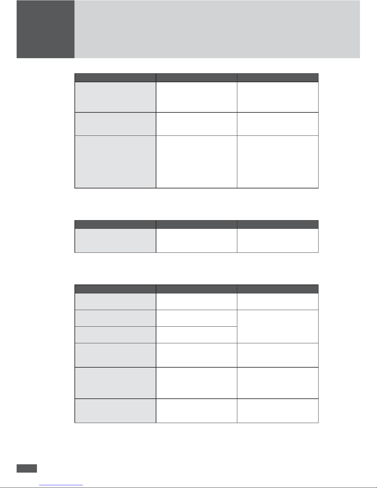
7.2 Booting
Status message Description
Irradiance too low The solar irradiation or rather the available output is too low for mains
operation.
Startup… The system checks the internal hardware and software components
before connecting to the mains.
Restart delay The system disconnected from the mains and is delaying re-connection
to the mains.
Idle The system does not start since at least one power unit is unavailable
for the MCU.
7.3 Mains operation
Status message Description
Mains operation The system has been connected and is feeding power to the mains.
Maximum power The system limits the fed output to the maximum permissible output.
Limiting the output can occur when the PV generator has been overdimensioned or in the event of high irradiation.
Idc limitation The system limits the DC input current to the maximum permissible
value. This can occur if the PV generator was designed so that the
current in the MPP is higher than the maximum permissible DC current
of the system.
Iac limitation The system limits the input mains current to the maximum permissible
value. This can occur in response to major uctuations in irradiation,
low mains voltage, or due to an over-dimensioned PV generator.
Restart limitation The system increases the effective power upon completion of an
external limitation with a de ned progression (Pac Progression and/or
Soft Start).
Frequency limitation The system limits the fed-in effective power due to an active frequen-
cy-dependent power reduction - P(f) mode.
External limitation The fed-in effective output of the system is limited via a remote access.
Remote controlled The system is controlled remotely by solar plant controller or by radio
ripple control receiver.
7.4 Communications activity
The communications activity of the MCU is displayed via two different symbols on the
graphical display.
Symbol Description
This symbol is displayed when the MCU sends or receives data (via RS485 or
Ethernet).
This symbol is displayed when there is an Ethernet connection (corresponds to the
"Link" display on network cards).

77
8 Troubleshooting
Sputnik Engineering delivers only SolarMax inverters which have stood up to our extensive testing regime. Moreover, each inverter is subjected to several hours of endurance
testing under full-load conditions.
This section describes in several tables all the possible error messages, their possible
causes and suggestions on how to remedy them.
If despite this your PV power plant suffers a malfunction or an error we recommend these
procedures:
DANGER
Work on the PV power plant and on the opened inverter must be performed solely by
quali ed electricians. Switch off the inverter and make sure that the DC and AC feed
lines are dead before you start work on the opened device.
1. Make sure that the system and PV generator have been correctly installed.
2. Check the cable connections and follow the instructions contained in the Installation
Manual.
3. Determine the cause of the malfunction by consulting the message on the graphic
display unit. Section 8.2, “Diagnosis & corrective steps” explains possible ways of
correcting malfunctions.
4. If you cannot correct the malfunction using the recommended procedures, or you are
not sure what sort of fault is involved, please contact our SolarMax Service Centre.

78
en
8.1 SolarMax Service Center
If you have technical questions or dif culties our Service Centre would be happy to help
you. If you have questions about central inverter malfunctions we need from you the following details:
■ Device type
■ Serial Number S/N
■ Installation location
■ Information about the malfunction you are experiencing (status message, etc.)
Availability
The contact details of the SolarMax Service Center can be found overleaf.
Sputnik Engineering AG
Länggasse 85
CH-2504 Biel/Bienne
8.2 Diagnosis & corrective steps
The following tables describe how to troubleshoot malfunctions. If the steps suggested
do not correct the malfunction please contact the SolarMax Service Centre immediately.
8.2.1 General troubleshooting
Problem Cause Steps
The display remains blank MCU or display is defective. Notify the SolarMax Service
Centre.
8.2.2 Warnings
Warning Cause Measure
Power unit malfunction At least one power unit has
a malfunction. The system
will continue to feed into the
mains.
Contact the SolarMax service
centre.
Failure temp. sensor A temperature sensor in
the system has ceased
functioning.
Failure fan The displayed fan is defective.
79
Warning Cause Measure
Burst error The system disconnected from
the mains ve times or more
on the same day. The warning
is displayed for the remainder
of the day. The error counter
will be reset when the system
is restarted in the morning.
Check the status logger of
your system in MaxWeb xp (if
available) or check the mains
parameters. If this problem
occurs frequently, contact the
SolarMax service centre.
Flash error A ash error has occurred. Contact the SolarMax service
centre.
Ief too high The earth fault current in the
potential equalisation set
(PAS) is too high (can only be
displayed if the PAS is used).
There is an insulation fault in
the PV generator.
Correct the insulation fault in
the PV generator.
Insulation fault DC There is a short-circuit in the
PV generator to earth.
Correct the short-circuit.
Poor wiring of the PV
generator.
Repair the wiring.
High creeping currents in
the PV generator caused by
dampness.
Seal the generator connection
box better and improve the
insulation materials.
Note: Check the setting of the functions Vsym Monitor or Vsym
AC Monitor.
Power unit blocked At least one power unit is
blocked temporarily.
Switch off the main switch Q7
and then switch it back on in
order to remedy the blocking
(or wait for the next restart of
the system).
RTC error The RTC (real-time clock) in
the MCU has a malfunction, the
date and time were re-set.
Set the time and date correctly
(see 4.5.2.6 “Settings”.
If this problem occurs frequently, contact the SolarMax
service centre.
Fuse failure PAS Fuse failure in the potential
equalisation set (PAS) (can
only be displayed when using
the PAS).
Contact the SolarMax service
centre. Note: Check the setting of the fuse failure PAS
function.
Temperature limitation The feed-in power has been
temporarily reduced to limit the
temperature of the system.
Clean the fan grids and
improve ventilation in the
operations room.
Warning MaxConnect The alarm contact X501 of the
MCU was closed.
Check the generator connection box (MaxConnect)
connected to the alarm contact
X501.
80
en
8.2.3 Malfunctions
Status message Cause Measure
Vdc too high The DC input voltage of an
individual power unit or the
system is too high.
Switch off all DC circuitbreakers immediately and then
disconnect the PV generator
from the system. Check the PV
generator’s dimensioning.
Vdc too low The DC input voltage has
dropped to too low a value.
Wait for the next restart of the
inverter and check whether it
starts mains operation.
No mains
No mains BP
The AC circuit-breakers are
switched off.
Switch on the AC circuit-breakers Q2, Q4, and Q6.
There is no mains voltage
or the AC feed line has been
disconnected.
Check the AC feed line.
Mains error The grid was shut down.
If this occurs repeatedly,
contact the responsible grid
operator.
Frequency too high
Frequency too high BP
The mains frequency is outside
of the f max 1 or f max 2 limit
values.
Frequency too low
Frequency too low BP
The mains frequency is outside
of the f min 1 or f min 2 limit
values.
Vac too high
Vac too high BP
The mains voltage at the
speci ed phase is outside of
Vac max 1 or Vac max 2 limit
values.
Vac too low
Vac too low BP
The mains voltage at the
speci ed phase is outside of
Vac min 1 or Vac min 2 limit
values.
Vac 10min too high
Vac 10min too high BP
The maximum 10-minute average value of the mains voltage
(Vac 10 min max.) is too high.
Insulation fault DC There is a short-circuit in the
PV generator to earth.
Correct the short-circuit.
Poor wiring of the PV
generator.
Repair the wiring.
High creeping currents in
the PV generator caused by
dampness.
Seal the generator connection
box better and improve the
insulation materials.
Note: Check the setting of the functions Vsym Monitor or Vsym
AC Monitor.
81
Status message Cause Measure
Fuse failure PAS Fuse failure in the potential
equalisation set (PAS) (can
only be displayed when using
the PAS).
Contact the SolarMax service
centre. Note: Check the setting of the fuse failure PAS
function.
Incorr. rotation dir. The rotational direction of the
connected mains phases is
wrong.
Connect the mains phases
properly.
Error ext. control The communication to the
remote control is interrupted.
The time limit between two
control commands was
exceeded.
Once the remote control reestablished communication,
the system will automatically
continue mains operation. If
this occurs repeatedly,
please check the network
connections.
8.2.4 Error
Status message Cause Measure
Device error (+ error code) An internal fault has occurred
in the system.
Check the two-digit error code
displayed and contact the
SolarMax service centre.
8.2.5 Blockages
Status message Cause Measure
Main switch off Main switch Q7 is in “OFF”
position.
Switch on the main switch Q7.
Shutdown 1 The shutdown 1 (shutdown
contact 1) is activated.
Eliminate the shutdown /
blocking.
Shutdown 2 The shutdown 2 (shutdown
contact 2) is activated.
External blocking There is a 0% command from
MaxRemote (based on the grid
operator).
None. Wait until the grid operator suspends the blocking
of the system via MaxRemote.
Program firmware The system rmware is cur-
rently being updated.
None. The system automatically re-assumes mains operation once the rmware update
is complete.
Recurring short circuit The MCU detected several (>2)
short-circuits during a certain
period of time on the AC side.
Contact your grid operator in
order to eliminate the cause of
the short-circuits.
82
en
9 Maintenance
All SolarMax inverters work completely automatically. However, to ensure perfect operation over the course of several years, in addition to regular controls of the operating
and yield data via the inverter display or remote monitor we also recommend having the
simple maintenance work described below performed at regular intervals. The maintenance intervals must be set keeping the ambient conditions in mind (especially exposure
to dust).
DANGER
Work on the opened inverter or MCU must be performed solely by quali ed electricians. The inverter must be shut down before it is opened. Then the DC and AC feed
lines must be disconnected according to the instructions and secured against any
accidental reconnection.
9.1 Inspections by the plant operator
The following checks can be performed by the plant operator. If you discover problems
while performing these checks, contact the electrician in charge of maintenance or our
SolarMax Service Centre.
■ A functional check of the inverter via the graphics display on the MCU
■ On-site check of visible traces of wear and tear (damage, rain, snow, rodents, etc.)
■ Cleaning and check of plant room
9.2 Maintenance by a quali ed electrician
1. Switch off the inverter and make sure that the DC and AC feed lines are dead.
2. Then wait 5 minutes to give the internal capacitors time to completely discharge.
3. Open the inverter by removing the front cover plate.
4. Tighten the screws on the DC and AC terminals.
5. Carefully clean the fan and the fan screen.
6. Check if there are any foreign bodies (rodents, etc.) in the inverter and remove them.
7. Re-close the inverter.
83
CAUTION
Have you left any tools in the device?
8. Switch on the DC and AC feed lines and the inverter.
9. If the PV power plant has the MaxControl option, a communications test is advisable.
For this purpose contact our SolarMax Service Centre.
9.3 Testing grid monitoring
With the help of the test contacts the grid monitoring of the system can be tested. The test
can be carried out for both single MPPT operation and multi-MPPT operation.
The test contacts permit a separation of the measuring lines between the respective
power unit and the three phase voltages U L1, U L2, and U L3. This allows for connecting
an AC generator for grid simulation. A DC voltmeter can be connected to the test contacts
in order to check the control voltage of the AC contactors K1, K2, or K3. The power units
within the system must be tested separately. The test contacts are located on the top right
in the inverter, see the Installation Manual.
Prerequisites / aids
■ Suf cient solar irradiation during the test
■ 3-phase AC generator
■ DC voltmeter
Procedure
The following instructions describe the test for the inverter’s LT1 power unit. When testing
power unit LT2 or power unit LT3, please observe the corresponding information in the
square brackets.
DANGER
The functional test of the inverter’s grid monitoring is performed using high volt-ages
while the inverter is open. Coming into contact with exposed power lines or noninsulated electrical contacts may result in serious injury or death!
1. Switch off the system as described in 4.4 “Switching off the inverter”.
2. Open the inverter to be tested and remove the covers.
3. Loosen the slide switches of the test contacts U L1, U L2, U L3, and K1EN from termi-
84
en
nal block “LT1” secured by means of slotted-head screws. [power unit LT2: terminal
block “LT2”], [power unit LT3: terminal block “LT3”].
4. Slide all 4 slide switches downwards and secure the slide switches by tightening the
slotted screws.
5. Connect the three-phase AC generator to the test contacts U°L1, U°L2, and U°L3 on
terminal block “LT1” [power unit LT2: terminal block “LT2”], [power unit LT3: terminal
block “LT3”]. Only use the lower 4mm sockets on the test contacts.
Remember to connect the rotational eld of the generator phases to rotate clockwise.
6. Connect the DC voltmeter to measure the control voltage of the AC contactor at the
upper and lower test contact K1EN.
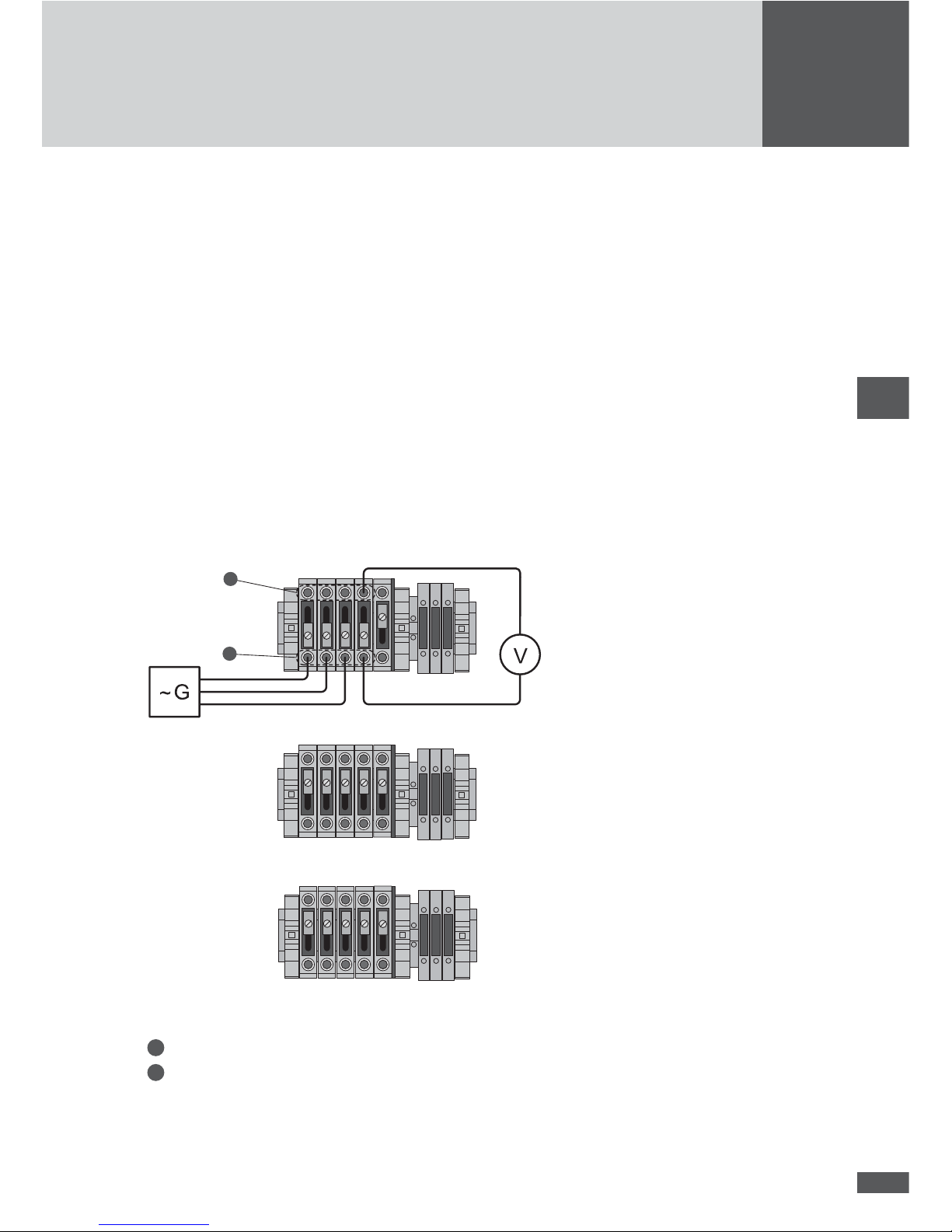
7. Check the wiring of the testing assembly against the following diagram:
Wiring diagram when testing power unit LT1
U L1
U L2
U L3
K1EN
LT 1
K1
U L1
U L2
U L3
K1EN
K1
U L1
U L2
U L3
K1EN
K1
2
1
LT 2
LT 3
Legend:
1
4mm sockets to control unit of the power unit
2
4mm sockets to the AC connections
G: AC generator
V: DC voltmeter
85
8. Switch on the DC circuit-breaker Q4 [power unit LT2: Q5], [power unit LT3: Q6]. The
other DC circuit-breakers and all AC circuit-breakers in the system remain switched
off.
9. Switch on the AC generator. The external conductor voltages must correspond to the
nominal mains voltage and frequency (3 x 280 U
ac / 50Hz).
10. Switch on the main switch Q7 (on the MCU). The inverter starts and, after roughly 30
seconds, switches to (simulated) mains operation.
11. Con rm that the control voltage of the AC contactor is 24 V
DC.
12. Now increase the voltage or frequency of any phase up to just under the set limit (see
11.5 “Individual country settings”.
CAUTION
Damage to the device possible! Never set the test voltage higher than 364 V (130 % of
the nominal voltage). This may damage the inverter’s measurement circuits. Sputnik
Engineering assumes no liability for damages which result from incorrectly conducted
tests.
13. Slowly increase the phase voltage or the frequency beyond the limit. Check whether
the inverter’s grid monitoring reacts appropriately: the measured control voltage of
the AC contactor must drop to 0V.
The test for power unit LT1 is completed when the control voltage of the AC contactor
drops.
14. Switch off the main switch Q7 (on the MCU).
15. Switch off the AC generator.
16. Switch off the DC circuit-breaker Q4 [power unit LT2: Q5], [power unit LT3: Q6] (all
the DC circuit-breakers are switched off).
17. Remove the AC generator and the DC voltmeter from the inverter.
18. Slide the 4 slide switches of the test contacts back into the upper position and screw
them down rmly.
19. If required, repeat the test for power units LT2 and LT3: in each case start with step
3 of these instructions. Pay attention to the information in the square brackets.
20. Remove all tools from the inverter.
21. Attach the covers and close the inverter.
22. If required, repeat the test for the remaining power units of the system.
23. Switch on the system as described in 4.3 “Switching on the inverter”.
The system is back in normal mains operation.

86
en
10 Disposal
Please dispose of the inverter at the end of its service life in compliance with the disposal
regulations currently valid where it is installed. You can also return the inverter at your
own cost for professional disposal to Sputnik Engineering (address as stated in the section on “Troubleshooting”).

2013/04
SolarMax Service Center
Deutschland +49 180 276 5 276
Schweiz / Svizzera / Suisse +41 32 346 56 06
France +33 4 72 79 17 97
Italia +39 0362 312 279
España +34 902 160 626
Benelux +32 2 535 77 32
Česká Republika
+420 222 191 456
United Kingdom +44 208 973 2556
Ελλάδα +30 210 727 91 61
България +39 0362 312 279
Australia +61 2 8667 3161
Other countries +41 32 346 56 06
Fax +41 32 346 56 26
E-Mail hotline@solarmax.com
www.solarmax.com/service
 Loading...