

Instruction manual
SolarMax MT series
6MT2 / 8MT2 / 10MT2 / 13MT2 / 15MT2 / 13MT3 / 15MT3

SolarMax Produktions GmbH
Zur Schönhalde 10
D-89352 Ellzee
E-Mail: info@solarmax.com
© SolarMax Produktions GmbH 2015


4
Contents
1 About this instruction manual. . . . . . . . . . . . . . . . . . . . . . . . . . . . . . . . . . . . . . . 6
1.1 Target group. . . . . . . . . . . . . . . . . . . . . . . . . . . . . . . . . . . . . . . . . . . . . . . . . 6
1.2 Where to keep this manual. . . . . . . . . . . . . . . . . . . . . . . . . . . . . . . . . . . . . . 6
1.3 Symbols used. . . . . . . . . . . . . . . . . . . . . . . . . . . . . . . . . . . . . . . . . . . . . . . . 6
2 Safety instructions. . . . . . . . . . . . . . . . . . . . . . . . . . . . . . . . . . . . . . . . . . . . . . . . 7
2.1 Appropriate use . . . . . . . . . . . . . . . . . . . . . . . . . . . . . . . . . . . . . . . . . . . . . . 7
2.2 Symbols on the inverter . . . . . . . . . . . . . . . . . . . . . . . . . . . . . . . . . . . . . . . . 8
3 Description . . . . . . . . . . . . . . . . . . . . . . . . . . . . . . . . . . . . . . . . . . . . . . . . . . . . . . 9
3.1 Views of the unit. . . . . . . . . . . . . . . . . . . . . . . . . . . . . . . . . . . . . . . . . . . . . 10
3.2 Dimensions . . . . . . . . . . . . . . . . . . . . . . . . . . . . . . . . . . . . . . . . . . . . . . . . .11
3.3 Block circuit diagram . . . . . . . . . . . . . . . . . . . . . . . . . . . . . . . . . . . . . . . . . .12
4 Installation . . . . . . . . . . . . . . . . . . . . . . . . . . . . . . . . . . . . . . . . . . . . . . . . . . . . . .13
4.1 Transport and storage . . . . . . . . . . . . . . . . . . . . . . . . . . . . . . . . . . . . . . . . .13
4.2 Siting . . . . . . . . . . . . . . . . . . . . . . . . . . . . . . . . . . . . . . . . . . . . . . . . . . . . . .13
4.3 Lightning protection . . . . . . . . . . . . . . . . . . . . . . . . . . . . . . . . . . . . . . . . . . .14
4.4 Scope of delivery . . . . . . . . . . . . . . . . . . . . . . . . . . . . . . . . . . . . . . . . . . . . .15
4.5 Installation . . . . . . . . . . . . . . . . . . . . . . . . . . . . . . . . . . . . . . . . . . . . . . . . . .15
4.6 Electrical connection . . . . . . . . . . . . . . . . . . . . . . . . . . . . . . . . . . . . . . . . . 16
4.6.1 Integrated overvoltage protection . . . . . . . . . . . . . . . . . . . . . . . . . .17
4.6.2 AC connection. . . . . . . . . . . . . . . . . . . . . . . . . . . . . . . . . . . . . . . . .18
4.6.3 DC connection. . . . . . . . . . . . . . . . . . . . . . . . . . . . . . . . . . . . . . . . 20
4.6.4 Status signalling contact . . . . . . . . . . . . . . . . . . . . . . . . . . . . . . . . 21
4.6.5 Monitoring external input . . . . . . . . . . . . . . . . . . . . . . . . . . . . . . . 22
4.6.6 Communications sockets . . . . . . . . . . . . . . . . . . . . . . . . . . . . . . . 23
4.6.7 External protective conductor . . . . . . . . . . . . . . . . . . . . . . . . . . . . 24
4.6.8 External residual-current device (RCD) . . . . . . . . . . . . . . . . . . . . . 24
4.6.9 External output control . . . . . . . . . . . . . . . . . . . . . . . . . . . . . . . . . 24
5 Commissioning. . . . . . . . . . . . . . . . . . . . . . . . . . . . . . . . . . . . . . . . . . . . . . . . . . 25
5.1 Switching on and off . . . . . . . . . . . . . . . . . . . . . . . . . . . . . . . . . . . . . . . . . 25
5.1.1 Switching on . . . . . . . . . . . . . . . . . . . . . . . . . . . . . . . . . . . . . . . . . 25
5.1.2 Switching off. . . . . . . . . . . . . . . . . . . . . . . . . . . . . . . . . . . . . . . . . 25
5.2 Initial start-up. . . . . . . . . . . . . . . . . . . . . . . . . . . . . . . . . . . . . . . . . . . . . . . 26
5.2.1 Requirements . . . . . . . . . . . . . . . . . . . . . . . . . . . . . . . . . . . . . . . . 26
5.2.2 Procedure . . . . . . . . . . . . . . . . . . . . . . . . . . . . . . . . . . . . . . . . . . . 26
5.2.3 Description of country-specic menus . . . . . . . . . . . . . . . . . . . . . 27
5.3 Conguration of the data communication interfaces . . . . . . . . . . . . . . . . . 29
6 Operation. . . . . . . . . . . . . . . . . . . . . . . . . . . . . . . . . . . . . . . . . . . . . . . . . . . . . . . 31

5
en
6.1 Graphics display . . . . . . . . . . . . . . . . . . . . . . . . . . . . . . . . . . . . . . . . . . . . . 31
6.2 Menu structure. . . . . . . . . . . . . . . . . . . . . . . . . . . . . . . . . . . . . . . . . . . . . . 32
6.3 Overview . . . . . . . . . . . . . . . . . . . . . . . . . . . . . . . . . . . . . . . . . . . . . . . . . . 33
6.4 Main menu . . . . . . . . . . . . . . . . . . . . . . . . . . . . . . . . . . . . . . . . . . . . . . . . . 33
6.5 Measured values . . . . . . . . . . . . . . . . . . . . . . . . . . . . . . . . . . . . . . . . . . . . 33
6.6 Statistics . . . . . . . . . . . . . . . . . . . . . . . . . . . . . . . . . . . . . . . . . . . . . . . . . . 35
6.6.1 Daily statistics. . . . . . . . . . . . . . . . . . . . . . . . . . . . . . . . . . . . . . . . 35
6.6.2 Monthly statistics . . . . . . . . . . . . . . . . . . . . . . . . . . . . . . . . . . . . . 36
6.6.3 Yearly statistics. . . . . . . . . . . . . . . . . . . . . . . . . . . . . . . . . . . . . . . 36
6.6.4 Total . . . . . . . . . . . . . . . . . . . . . . . . . . . . . . . . . . . . . . . . . . . . . . . 36
6.6.5 Reset. . . . . . . . . . . . . . . . . . . . . . . . . . . . . . . . . . . . . . . . . . . . . . . 37
6.7 Conguration . . . . . . . . . . . . . . . . . . . . . . . . . . . . . . . . . . . . . . . . . . . . . . . 37
6.8 Settings . . . . . . . . . . . . . . . . . . . . . . . . . . . . . . . . . . . . . . . . . . . . . . . . . . . 40
6.8.1 Implementing the settings . . . . . . . . . . . . . . . . . . . . . . . . . . . . . . . 41
6.8.2 Status relay. . . . . . . . . . . . . . . . . . . . . . . . . . . . . . . . . . . . . . . . . . 41
6.9 Information. . . . . . . . . . . . . . . . . . . . . . . . . . . . . . . . . . . . . . . . . . . . . . . . . 42
6.10 Auto Test according to DK 5940 . . . . . . . . . . . . . . . . . . . . . . . . . . . . . . . . . 42
6.10.1 Start Auto Test . . . . . . . . . . . . . . . . . . . . . . . . . . . . . . . . . . . . . . . 42
6.10. 2 Procedure . . . . . . . . . . . . . . . . . . . . . . . . . . . . . . . . . . . . . . . . . . . 43
7 Operating status . . . . . . . . . . . . . . . . . . . . . . . . . . . . . . . . . . . . . . . . . . . . . . . . . 44
7.1 Status messages and status LED . . . . . . . . . . . . . . . . . . . . . . . . . . . . . . . . 44
7.2 Booting. . . . . . . . . . . . . . . . . . . . . . . . . . . . . . . . . . . . . . . . . . . . . . . . . . . . 44
7.3 Mains operation . . . . . . . . . . . . . . . . . . . . . . . . . . . . . . . . . . . . . . . . . . . . . 45
7.4 Communications activity . . . . . . . . . . . . . . . . . . . . . . . . . . . . . . . . . . . . . . 45
8 Troubleshooting . . . . . . . . . . . . . . . . . . . . . . . . . . . . . . . . . . . . . . . . . . . . . . . . . 46
8.1 SolarMax Service Center . . . . . . . . . . . . . . . . . . . . . . . . . . . . . . . . . . . . . . 46
8.2 Diagnosis & measures . . . . . . . . . . . . . . . . . . . . . . . . . . . . . . . . . . . . . . . . 47
8.2.1 General troubleshooting . . . . . . . . . . . . . . . . . . . . . . . . . . . . . . . . 47
8.2.2 Warnings. . . . . . . . . . . . . . . . . . . . . . . . . . . . . . . . . . . . . . . . . . . . 47
8.2.3 Failures . . . . . . . . . . . . . . . . . . . . . . . . . . . . . . . . . . . . . . . . . . . . . 48
8.2.4 Error . . . . . . . . . . . . . . . . . . . . . . . . . . . . . . . . . . . . . . . . . . . . . . . 49
8.2.5 Blockings . . . . . . . . . . . . . . . . . . . . . . . . . . . . . . . . . . . . . . . . . . . 49
9 Maintenance . . . . . . . . . . . . . . . . . . . . . . . . . . . . . . . . . . . . . . . . . . . . . . . . . . . . 50
10 Disposal. . . . . . . . . . . . . . . . . . . . . . . . . . . . . . . . . . . . . . . . . . . . . . . . . . . . . . . . 50
11 Technical data . . . . . . . . . . . . . . . . . . . . . . . . . . . . . . . . . . . . . . . . . . . . . . . . . . 51
11.1 Country-specic settings . . . . . . . . . . . . . . . . . . . . . . . . . . . . . . . . . . . . . . 54
11.2 Efciency curve SolarMax 15MT3 . . . . . . . . . . . . . . . . . . . . . . . . . . . . . . . 54
11.3 Temperature-dependent output reduction (power derating) . . . . . . . . . . . . 54
12 Accessories and options . . . . . . . . . . . . . . . . . . . . . . . . . . . . . . . . . . . . . . . . . . 56
13 Warranty . . . . . . . . . . . . . . . . . . . . . . . . . . . . . . . . . . . . . . . . . . . . . . . . . . . . . . . 57
6
1 About this instruction manual
This instruction manual contains a description of the SolarMax MT series string inverters.
It furthermore tells you how to install, commission, and operate the inverters.
Familiarise yourself with the inverter functions and characteristics before you begin the
installation work. Carefully read the safety instructions in this instruction manual in particular, ignoring the safety instructions can result in serious injuries or death.
1.1 Target group
This instruction manual is written for the operator of the PV plant and the responsible
qualied electrician.
1.2 Where to keep this manual
The plant operator must ensure that this instruction manual is available to those responsible for the plant at all times. If this original document is lost, an up-to-date version of
this instruction manual can be downloaded from our website at all times (www.solarmax.
com).
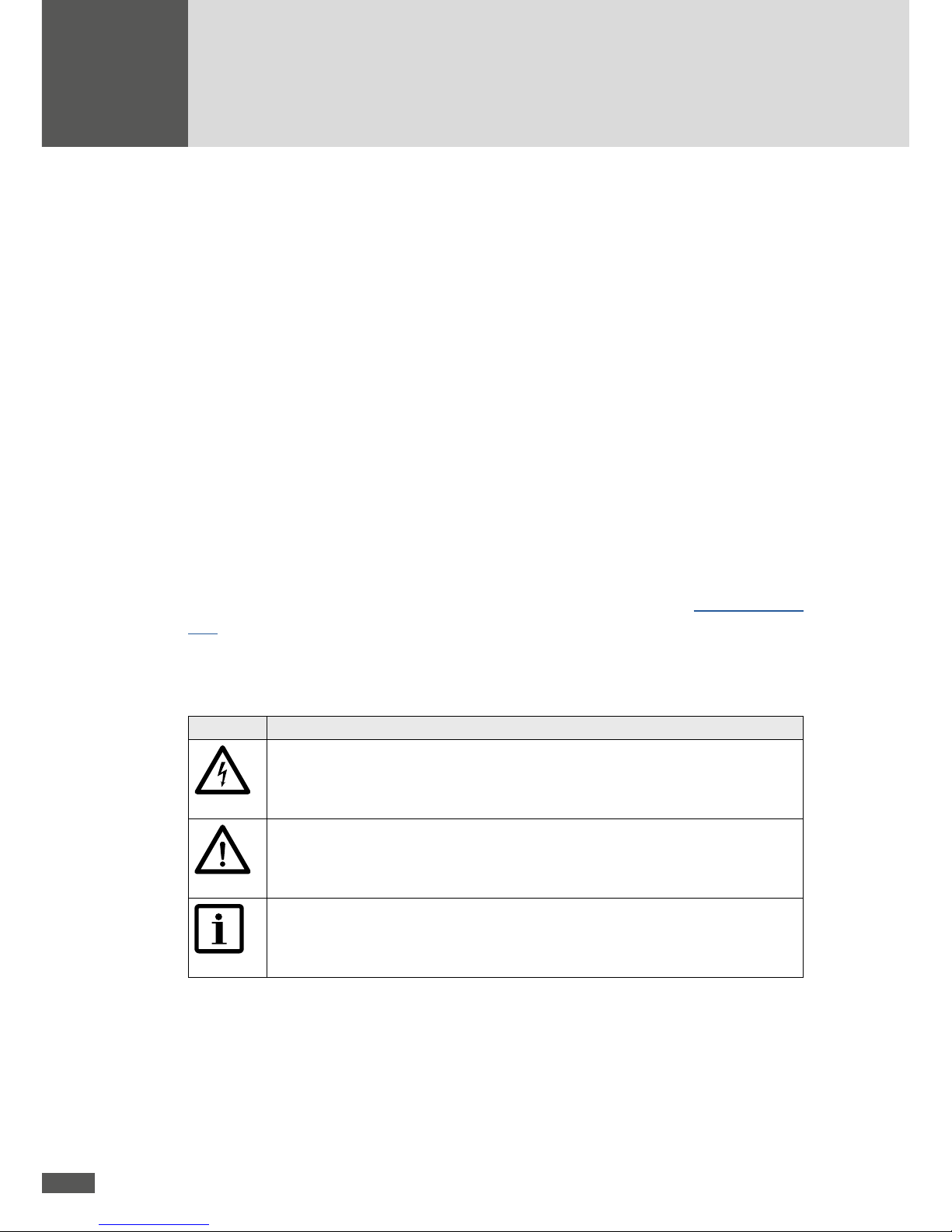
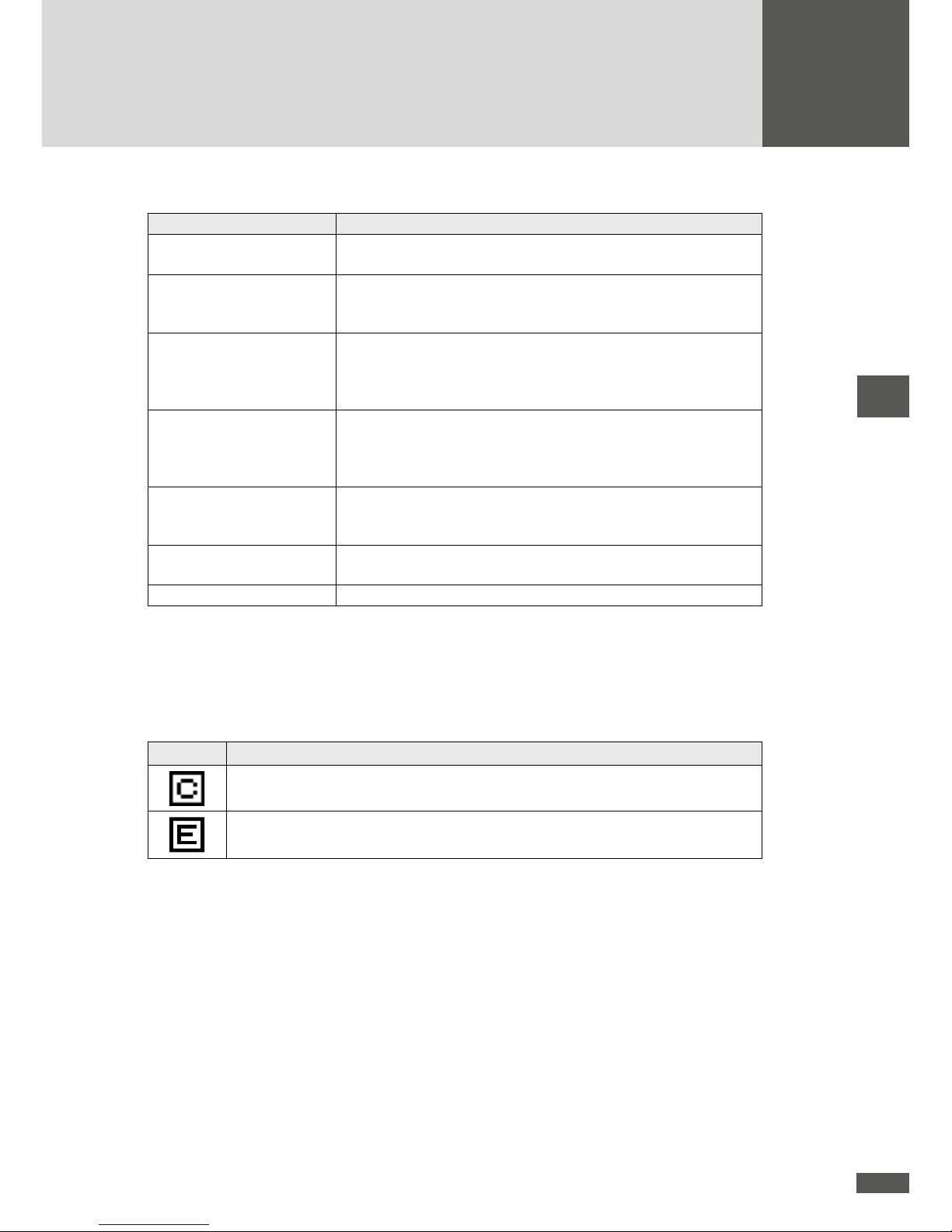
1.3 Symbols used
Symbol Description
DANGER
This symbol indicates that ignoring this instruction may directly lead to serious
injury or death.
CAUTION
This symbol indicates that ignoring this instruction may lead to damage to your
inverter or your PV plant.
NOTE
This symbol indicates information which is especially important for operating the
inverter.

7
en
2 Safety instructions
The MT series solar inverters have been designed and tested according to the latest technological advances and the currently valid product safety standards. However, ignoring
the safety instructions contained in this instruction manual may endanger the user, a third
party, or property. The qualied electrician and the operator of the PV plant can minimise
these risks by following the safety instructions at all times.
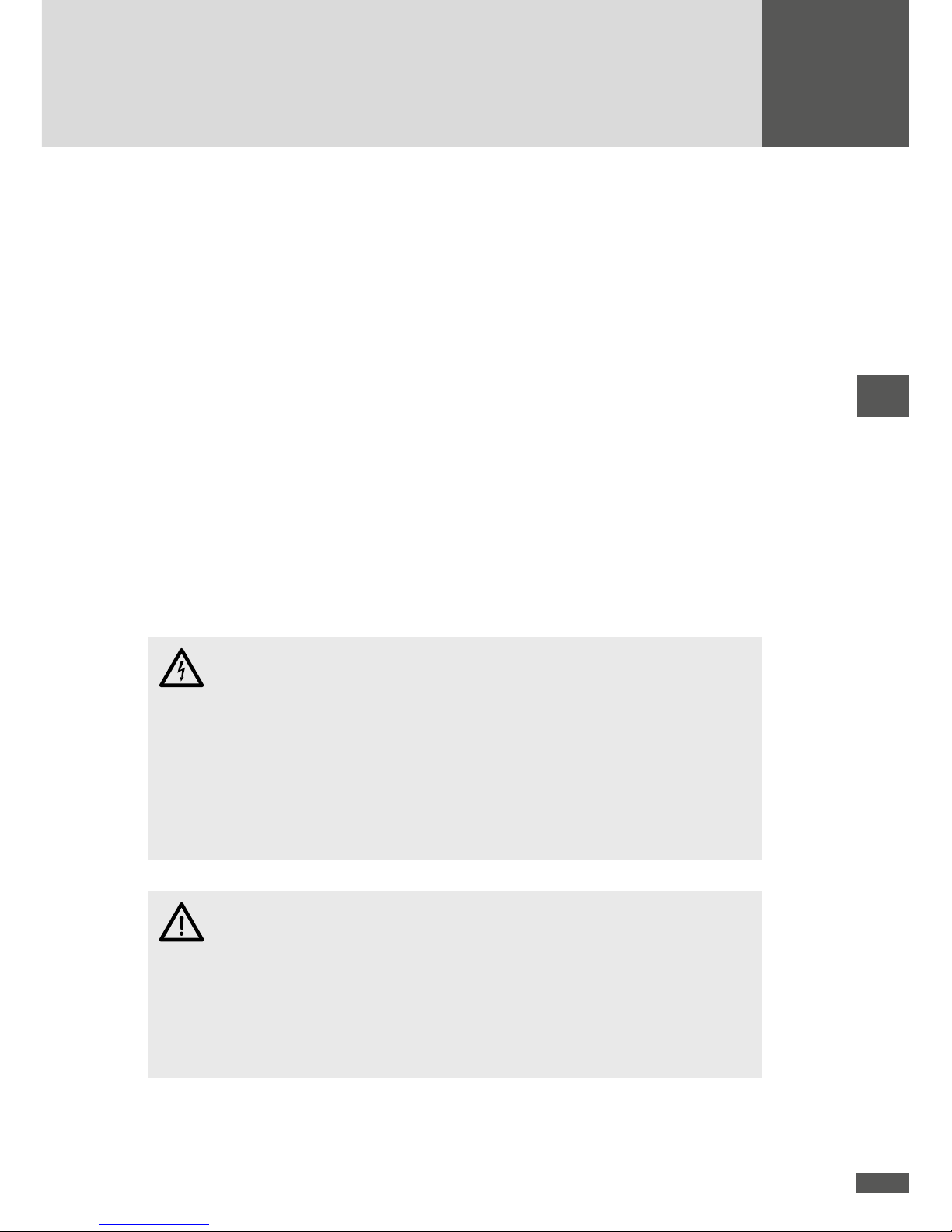
DANGER
Only qualied electricians who have already completely read and understood this
instruction manual in advance may install SolarMax inverters.
The photovoltaic generator supplies direct current to the inverter when the PV
modules are exposed to sunlight.
The inverters must remain closed at all times during operation.
The responsible electrician shall be responsible for complying with the applicable
local installation and safety regulations.
Ignoring the installation and safety instructions shall forfeit any and all warranty
and liability claims.
2.1 Appropriate use
The SolarMax MT series string inverters are designed exclusively to convert the direct
current generated by PV modules into grid-compliant alternating current.
The inverters may only be used in combination with PV modules which comply with the
IEC 61730 standard. Any other use, in particular the conversion of direct current from
batteries or other storage elements into alternating current is not permissible.
Any other use is contrary to the purpose for which the inverters were designed. SolarMax
Produktions GmbH accepts no liability for damages resulting from using inverters for purposes other than this. Any modications to the inverter performed by the plant operator
or the tter without any review or approval by SolarMax Produktions GmbH are prohibited.

8
2.2 Symbols on the inverter
Symbol Description
Protective conductor connection
DC disconnector Q1 position OFF - In this position the DC disconnector Q1 is off (open)
DC disconnector Q1 position ON - In this position the DC disconnector Q1 is on (closed)
Risk of death through high voltages! Only qualied electricians may
perform work on the inverter.
Careful - hot surfaces!
5 min
Risk of death due to high voltages! De-energize the inverter. Proceed to wait for 5 minutes before opening the inverter.
Only qualied electricians may perform work on the inverter.
Read the operating instructions - Please read and follow the instructions supplied with the inverter. Do not remove any symbols on the
inverter. Replace damaged symbols.
CE marking - The inverter complies with the requirements of the
European EMC Directive 2004/108/EC and the Low Voltage Directive 2006/95/EC.
C-Tick - compliance with the Australian EMC regulations
Do not dispose of the inverter and its accessory components in the
household waste.

9
en
3 Description
The SolarMax MT series string inverters convert the direct current (DC) of a photovoltaic
generator into grid-compliant alternating current (AC). In this, the current is inverted by
a two-phase, transformerless circuit type. The connection and synchronous feed of the
inverted current into the public power grid are permanently three-phase.
The inverter is operated completely automatically and depends on the power supplied by
the photovoltaic modules. If there is enough power, the inverter starts mains operation
and feeds the existing output into the power grid. If there is not enough power available
from the PV generator, the inverter disconnects from the grid and shuts down.
The two (SolarMax 6MT2 / 8MT2 / 10M T2 / 13MT2 / 15MT 2) and/or three (SolarMa x
13MT3 / 15MT3) independent MPP trackers adapt to a changed energy supply from the PV
generator with the help of two digital signal processors within seconds. The completely
digital current form regulation ensures an outstanding quality of the fed-in current and,
as a result, extremely negligible grid feedback.
During mains operation the integrated grid monitoring permanently checks various
parameters of the AC grid; in this, the set limit values depend on the installation site
selected. An integrated AC/DC sensitive leakage current sensor monitors the stray and
leakage currents at the generator end during operation. If values exceed or fall short of the
set limit values, the inverter disconnects from the grid within a pre-set time. Reconnection
is attempted after a dened period of time.
A graphics display with three buttons permits comfortable operation of the inverter and
reading out all important operating data. The integrated data logger allows for recording
the most important operating parameters of the most recent 31 days, 12 months, and
10 years.
The built-in temperature sensor monitors the temperature inside the casing; the heat is
dissipated to the outside by the cooling ns on the back of the inverter. The heat exchange
with the ambient air is actively supported by two controlled fans producing a horizontal
air ow. If the temperature inside the casing becomes excessive, the inverter gradually
reduces its output power.

10
3.1 Views of the unit
Front view
1
1
Graphics display with status LED and three buttons
Side view left
432 5
2
Fan cover (air intake)
3
Name plate
4
DC disconnector Q1
5
Connection option for external protective conductor
Side view right
6
6
Fan cover (air outlet)

11
en
3.2 Dimensions
545
77
200
[mm]
745
12
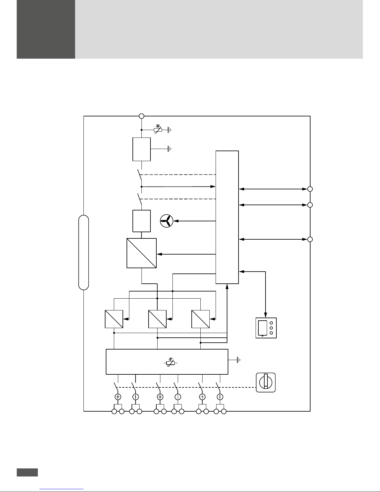
3.3 Block circuit diagram
I
0
U
U
Status signalling contact
Ethernet / RS485
DC measurement
AC measurement
Fan
RS485
Monitoring external input
Inverter control
Booster control
Inverter
LC lter
Booster 2
Booster 1
SolarMax MT seriesDCDC
AC
K2K1
DC
DC
DC
Booster 3
DC
DC
Control unit
Graphics display
* Tracker 3 only SolarMax 13MT3 / 15MT3
DC disconnector Q1
DC input
Tracker 1
DC input
Tracker 2
DC input
Tracker 3 *
AC output
EMC lter
EMC lter
13
en
4 Installation
4.1 Transport and storage
During transport, attention must be paid to the following aspects:
During transport and any interim storage period, you must ensure that the local
ambient conditions (temperature and humidity) are always within the limit values
specied in the technical data. Any longer term, unattended, and unprotected interim
storage of the inverter in the open must be avoided.
Since this is a two-section package, you must absolutely ensure that the top and the
bottom of the package are glued together when the inverter is returned or
forwarded.
4.2 Siting
Choosing a suitable location for the inverter is decisive for its operating safety as well as
its expected service life and efciency.
When you select an installation site for the inverter please follow these instructions:
DANGER
The inverter and all feed lines must be installed out of reach of children or pets
(especially rodents).
Install the inverter in an environment that is free of ammable gases and uids.
Never install the inverter near combustible materials. The installation base must
be non-combustible.
The installation substrate must have sufcient structural strength.
CAUTION
The casing of the SolarMax MT series inverter complies with protection class
IP65. Thus, it can be installed outdoors, but the stated IP protection is only
ensured if the included AC connector, an appropriate DC connector (MultiContact
series 4) and the recommended RJ45 communications connectors are used.
When installing outdoors do not expose the inverter to direct sunlight.

14
CAUTION
The inverter must be installed in a location protected from rain and snow.
When installing several inverters next to each other, you must observe a distance
of 0.5 metres between the inverters. This distance prevents the mutual thermal
inuence due to the hot exhaust air of the ventilation systems.
The ventilation inlet and the ventilation outlet must never be covered. Free air
circulation is absolutely necessary to permit the inverter to function properly.
The installation location must meet the requirements related to electromagnetic
emissions (EN 61000-6-4).
NOTE
For easy installation of the DC and AC supply lines you should design a freely
accessible area of approx. 0.5 metres in height below the inverter.
An excessive amount of dust as well as salt and ammonia vapors in the inverter’s
ambient air must be avoided. Unsuitable installation locations increase the risk of
corrosion and reduce the service life of the inverter.
Make sure there is sufcient ventilation if the inverter is installed inside a building
or plant room. Maximum useful life requires that the ambient temperature is never
higher than 30°C.
Due to possible noise emissions, we do not recommend installation in or near
residential rooms or workplaces.
The ambient air should be dust-free to avoid excessive dirt on the heat sink and
fans. Rooms with heavy concentrations of dust (e.g. in cabinetmaking or metal
workshops, hay storage buildings) are not suitable installation locations.
4.3 Lightning protection
The requirements for appropriate lightning protection for a PV plant depend on many different factors (plant size, how the cables are run, the modules used, the surroundings,
etc). A project-specic protection concept must be developed by a qualied person.
15
en
4.4 Scope of delivery
Inverter
AC connector
Installation plate for wall installation
Instruction manual and quick guide
Accessory kit (installation material for wall installation and earth connection)
4.5 Installation
The inverter can be installed easily using the included installation plate and installation
material on a level installation base. You will nd more information about how to properly
install the inverter in the quick guide included in the delivery.
1. Drill four holes, Ø 8mm in diameter and with a depth of 60mm (drill hole pattern
shown in the gure “Installation plate”; page 16).
2. Insert the dowels.
3. Attach the installation plate using the four 6 x 50 screws and washers.
4. Mount the inverter carefully from above into the holder.
NOTE
As soon as the inverter is completely mounted, you can secure it additionally with the
included splint or a padlock (not included in the delivery).

16
Installation plate
235
[mm]
100
10
7
2
1
1
For the other measurements see Section 3.2.
1
Holes for padlock (against theft)
2
Recesses for lock with splint
4.6 Electrical connection
The MT series inverters have the following connection options:
1 2 3 44 5 6 7
17
en
No. Connection
SM8MT2 /
SM6MT2
SM10MT2 /
SM13MT2 /
SM15MT2
SM13MT3 /
SM15MT3
1 - 3 DC
1 x 2 / 1 x 1
strings MC4
2 x 2 strings MC4 3 x 2 strings MC4
4
External protective
conductor
2 x thread M6
5
Status signalling
contact
M12 plug with potential-free switch contact
6 AC 5-pole Amphenol plug-in connector
7 Communication 2 x RJ45 (sealed tight by protective caps)
DANGER
Before you start the installation work, make sure that all the provided DC and AC
feed lines to the inverter are de-energised. The installation work must be performed by a qualied electrician who adheres to the recognised rules of electrical
installations and personal health and safety regulations.
All the feed lines to the inverter must be appropriate for the expected voltages,
currents, and ambient conditions (temperature, UV load, etc.).
Make sure that all lines are laid tension-free.
CAUTION
The inverter must be installed in a suitable location (see Section 4.2).
Make sure that all the lines into the inverter are laid so as to avoid earth leakage
or short circuits.
4.6.1 Integrated overvoltage protection
The MT series inverters have integrated surge arresters (varistors) on both the DC and
AC ends.
On the DC end, each MPP tracker has a surge arrester from the plus and minus pole
to the earth. The surge arresters comply with requirement class C as dened in VDE
0675-6 or type 2 as dened in EN 61643-11.
On the AC end, each grid phase (L1/L2/L3) has a surge arrester to the earth. The
surge arresters comply with requirement class D as dened in VDE 0675-6 or type 3
as dened in EN 61643-11.
18
4.6.2 AC connection
CAUTION
The MT series inverters must be connected to a mains connection point meeting
at least the requirements of overvoltage category 3.
Mains fuses and cable cross-sections
The following table contains information about the recommended mains fuses and the
minimum required line cross-sections necessary for the AC feed line:
SM8MT2 /
SM6MT2 SM10MT2
SM13MT2/
SM13MT3
SM15MT2/
SM15MT3
Mains fuses
(C characteristic)
16 A 20 A 25 A 25 A
Minimum line
cross-section AC and
protective conductor
2.5 mm
2
4 mm
2
4 mm
2
4 mm
2
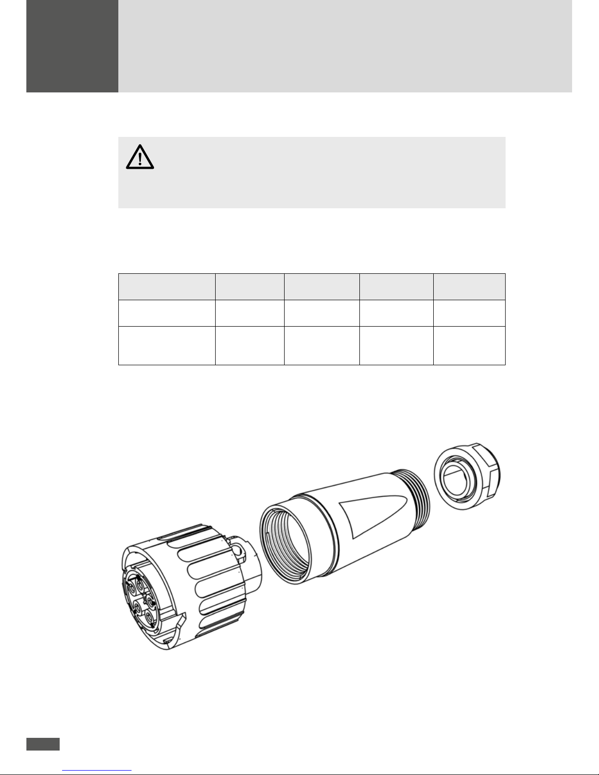
Confectioning the AC connector
The AC feed line is connected to the inverter using the included Amphenol AC connector:
Casing
Retainer ring
Contact base

19
en
The AC connector must be connected using a exible cable as described in
EN 60309-2/VDE 0623.
The permissible cable diameter is 11 to 20mm.
Cable strands with a maximum cross-section of 6mm² can be connected.
Procedure
1. If the cable diameter is > 16mm, remove the blue inlay from the retainer ring.
2. Slide the retainer ring and the casing over the cable.
3. Press the appropriate ferrules on the stripped strands.
4. Connect the individual cores one after another to the contact base:
– Phase L1 to the screw terminal with the number 1
– Phase L2 to the screw terminal with the number 2
– Phase L3 to the screw terminal with the number 3
– Neutral conductor N to the screw terminal with the number 4
– Protective conductor PE to the screw terminal with the earth symbol
– Tightening torque: 0.7 Nm
5. Check that each individual core is securely connected.
6. Screw the casing onto the contact base.
– Tightening torque: 1-2 Nm
7. Screw the retainer ring onto the casing.
– Tightening torque: 5 Nm
The AC feed line can now be connected with a twisting movement to the AC connection
of the inverter (bayonet connector with locking pin). As soon as the correct position is
reached, the connector slips onto the AC connection. The inverter is now rmly connected
to the AC grid.
DANGER
Connect the protective conductor as carefully as possible.
CAUTION
As soon as the bayonet connector has slipped in, the AC connection can only be
re-opened using a tool (slotted screwdriver size 2).
Open the AC connection carefully by pressing down the locking pin on the contact
insulator and turning the AC connector counter-clockwise to break the
connection.

20
4.6.3 DC connection
The inverters are quipped with 2 (SolarMax 6MT2 / 8MT2 /10MT2 / 13MT2 / 15MT2)
resp. 3 (SolarMax 13MT3 / 15MT3) MPP trackers. Each tracker has two plus and minus
poles for the connection of two strings per tracker input. A string can be connected at
tracker 2 of each of the inverters SM6MT2 and SM8MT2.
Detailed view of DC connections
1
2
1
Plus connections
2
Minus connections
The position of the plus and minus connections is identical for all DC inputs (1 to 3).
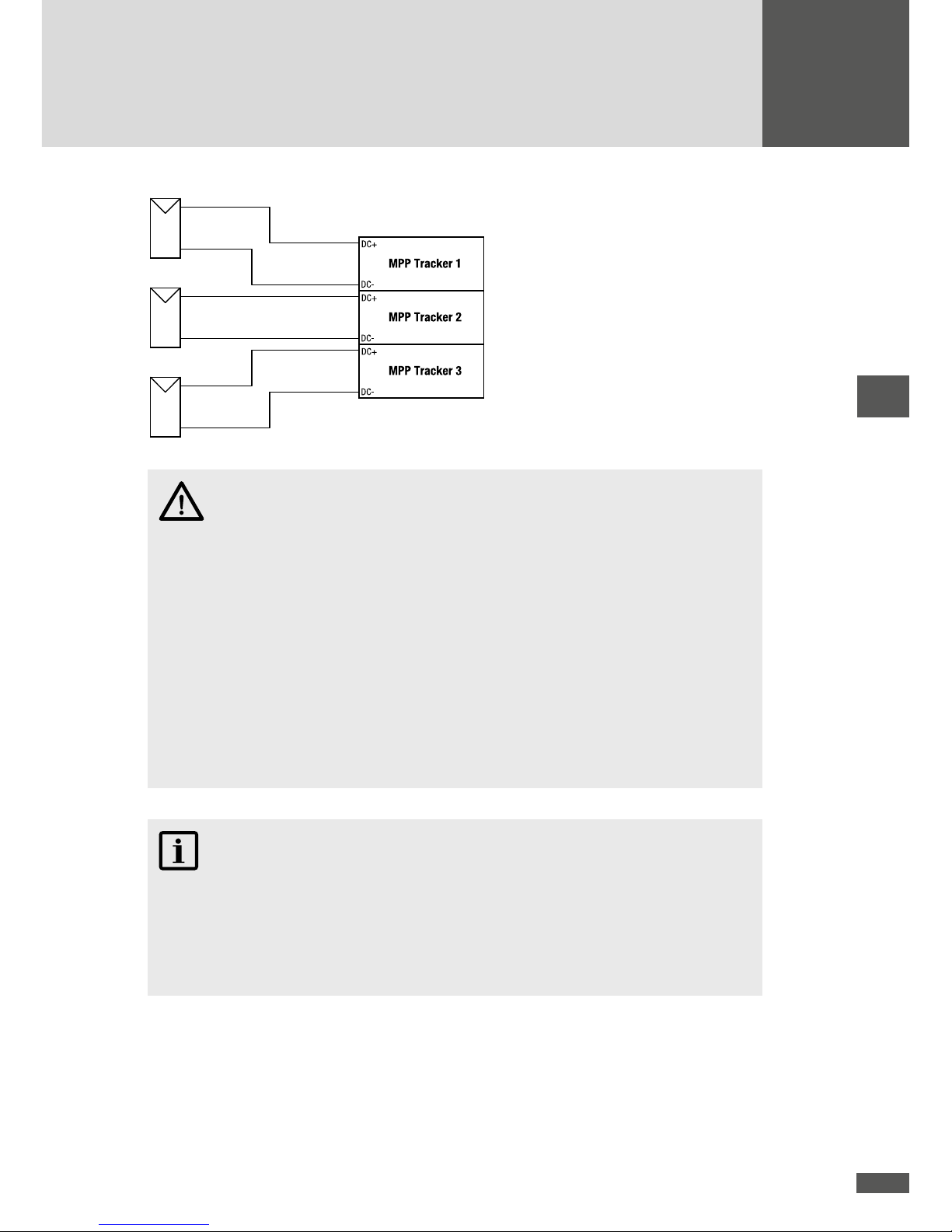
Trackers 1 to 3 operate independently of each other, thus enabling simultaneous connection of strings with different characteristics (orientation, dimensioning, module type)
to a shared inverter. The plus and minus connections of different trackers must not be
connected to each other:
MPP Tracker 2
MPP Tracker 1
MPP Tracker 3
DC+
DCDC+
DCDC+
DC-
Wrong connection!
The plus and minus feed lines for trackers 1 to 3 must be run to the inverter separately
from each other:
21
en
Correct connection!
CAUTION
Only use MC4 connectors by MultiContact or connectors compatible with these
for the connection of the DC supply lines.
Due to the transformerless circuit type of the MT series inverters, the plus or
minus pole of the PV generator must not be earthed under any circumstances.
Otherwise, the isolation monitoring in the inverter prevents a mains connection.
Select cable cross-sections for the DC feed lines corresponding to your plant con-
guration and in conformance with the valid local installation regulations.
Remember that the shared plus and minus pole of a string must always be con-
nected to the same tracker.
The position of the DC disconnector Q1 must be “O” (Off).
NOTE
If required, it is possible to oversize the PV generator output with respect to the inverter
output. The oversize factor should not exceed 1.5. For example, for the SM15MT3 a
PV generator output of 22.5 kW is possible. Please contact us if you are intending to
oversize your PV generator output by a larger factor.
4.6.4 Status signalling contact
The status signalling contact enables remote retrieval of the operating status of the
inverter. The status signalling contact is located in the connection area of the inverter, see

22
Section 4.6. A suitable M12 mating connector to connect to the status signalling contact
can be ordered from the SolarMax Service Centre.
Remote retrieval of the operating status can be congured, see Section 6.8.2.
Connecting conditions
V
Max
250VAC / 30VDC
I
Max
1.5 A
Pinout
Contact Description
1 NO (normally open: open when idle)
2 COM
3 NC (normally closed: closed when idle)
4 Not used
Contact diagram (idle)
COM
NC
NO
4.6.5 Monitoring external input
This interface can be used to connect the inverter to an external grid monitoring system
which will disconnect the inverter from the mains grid from a remote location when this
is needed.
If the “Monitoring external input” function is activated, the grid relays of the inverter can
be used as interconnection circuit breakers of the central G/P protection. The function
is activated during initial start-up (see Section 5.2) or subsequently using the service
software MaxTalk 2 Pro. Remote retrieval of the operating status, as described in Section
4.6.4, is no longer possible when monitoring of the external input is activated.
Functionality
The contacts 1 and 4 of the status signalling contact are used to monitor the external
input. When there is phase voltage between contact1 and contact4, the grid relays K1
and K2 are closed (see Section 3.3). If phase voltage is not present between contacts 1
and 4, the grid relays are open and the inverter disconnects from the grid.

23
en
Contact 1 / contact 4 Grid relays K1 and K2
Phase voltage (L1, L2, or L3) present closed
no phase voltage present open
Connecting conditions
See Section „4.6.4 Status signalling contact“
Pinout
Contact Description
1 Phase (L1, L2 or L3)
2 Not used
3 Not used
4 Neutral conductor N
4.6.6 Communications sockets
The SolarMax MT series inverters have two RJ45 sockets for data communication within
a MaxComm network:
The left-hand RJ45 socket is only an RS485 interface. The RS485 interface is used
for connections to other SolarMax inverters or accessories with MaxComm
interface.
The right-hand RJ45 socket can be used both as an RS485 and as an Ethernet inter-
face; the desired function can be toggled in the “Settings” menu. The Ethernet interface is used for connecting an inverter directly to a PC or to MaxWeb xp. However, if
both sockets are congured as RS485 interfaces, a network containing several
RS485 nodes can be set up.
NOTE
If the RJ45 sockets are used and the inverter is exposed to the weather, please use
products from the VARIOSUB-RJ45 range with IP67 protection class from Phoenix
Contact. This ensures that the installation meets the requirements of IP65.
RJ45 plug-in connector, 8-pin (item no. 1658493)
Available from www.phoenixcontact.com.

24
4.6.7 External protective conductor
The inverter’s stray current to earth can reach values of more than 3.5mA (AC) or 10mA
(DC) during operation. In accordance with IEC/EN 62109-1, a second protective conductor
must therefore be connected. This can be connected to one of the two M6 threaded connections (see Section 4.6).
Connecting conditions
Minimum conductor cross-section: 10 mm²
M6 screw tightening torque: 10.0 Nm
4.6.8 External residual-current device (RCD)
The SolarMax MT series inverters have an integrated AC/DC sensitive fault current
sensor. This sensor is able to distinguish between the operational capacitive stray currents (caused by capacities of the PV modules to the earth) and fault currents (caused by
touching a pole of the PV generator). The inverter disconnects immediately from the grid
as soon as an exceedance of the absolute limit value (300 mA, important in relation to re
protection) or a sudden increase in the DC-end fault current (30 mA, important to protect
against personal injury) has been detected.
If an additional external residual current device (RCD) is wanted, an RCD of type A should
be chosen. The residual current rating of the RCD depends on the number of inverters in
the PV power plant. For each inverter, a residual current rating of at least 100 mA should
be allowed for. For example, in a PV power plant with three inverters an RCD with a
residual current rating of at least 300 mA should be used.
4.6.9 External output control
The MaxWebxp data logger and its MaxRemote extension can be used to set the set
values for active and reactive power (e.g. for remote controlled output limitation). The
MaxWeb xp is connected via the Ethernet or via the inverter’s RS485 interfaces (see Section 4.6.6), i.e. via a MaxComm network.
You can download the installation instructions for the MaxWebxp and MaxRemote accessory components from our website: www.solarmax.com/en/downloads/
data-communication/maxweb-xp.

25
en
5 Commissioning
5.1 Switching on and off
All SolarMax inverters work completely automatically. When the PV generator supplies
enough power, the inverter switches on and then starts mains feed operation. At night,
or when the DC end is shut down, the inverter is disconnected from the grid. Operating
the inverter and the ability to communicate via the interfaces are only possible when the
inverter is switched on.
5.1.1 Switching on
1. Switch on the DC disconnector Q1
– The inverter switches on; after a couple of seconds, the graphics display is acti-
vated (assuming there is enough power coming from the PV generator)
2. Switch on the external AC disconnector
– The inverter switches to mains feed operation after roughly 30 seconds
5.1.2 Switching off
DANGER
The DC-end MC connectors may only be disconnected from the inverter if the DC
disconnector (Q1) is open. If the disconnector is not open, disconnecting the DC feed
lines during operation can result in dangerous arcs.
1. Switch off external AC disconnector (optional)
– The inverter is disconnected from the grid
2. Switch off the DC disconnector Q1
– The inverter shuts off after a few seconds

26
5.2 Initial start-up
When the inverter is started up for the rst time, initial setup starts automatically. This
procedure must only be carried out once during initial start-up. You can nd information
on the operation of the graphics display in Section 6.
5.2 .1 Requirements
Correctly connected DC supplies (AC connection is not required)
Sufcient solar irradiation
NOTE
Entering the country incorrectly may lead to problems regarding inverter operation
and to the withdrawal of the operating license by the respective grid operator.
You can restart initial start-up on the graphics display by pressing at any
time.
Thoroughly read the manual before starting initial start-up. Contact your grid ope-
rator or the SolarMax Service Centre if you have any doubt regarding the settings
you must select.
5.2.2 Procedure
1. Switch on the inverter as described in section 5.1.1. The “Initial setup” menu will be
displayed:
2. Select the display language from the “Language” menu.
3. If necessary, update the time and the date.
– The inverter saves the date entered as the initial start-up date.
– The “Country” menu will be displayed:

27
en
4. Select the correct country setting.
– Press
to conrm your entry.
– Depending on the country setting selected, additional menus may be displayed
(see Section 5.2.3).
– The “Monit. ext. input” menu is then displayed.
5. If appropriate, activate the function:
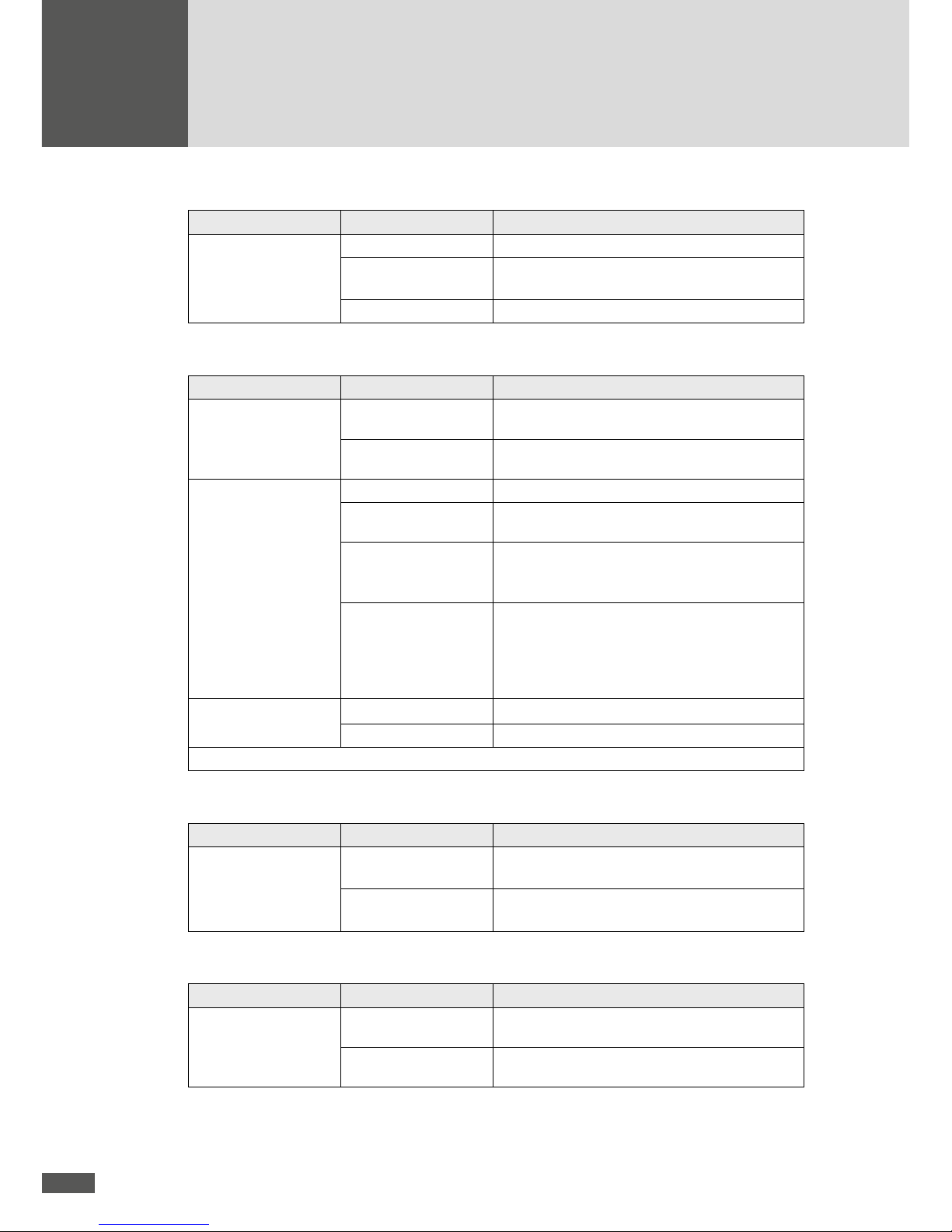
Menu Setting Description
Monit. ext. input Inactive
The function “Monitoring external input” is
switched off (default setting).
On
The function “Monitoring external input” is
switched on. The status signaling contact serves
as interface for the remote controlled deactivation
of the inverter via external grid monitoring (see
Section 4.6.5).
– The “Conrmation” menu is then displayed.
6. Check the data in the “Conrmation” menu.
7. To complete initial start-up, press
.
– The main menu will then be displayed (see Section 6.4).
– Should commissioning be taking place in Italy, the auto-test must be carried out
after the initial start-up (see Section 6.10).
5.2.3 Description of country-specic menus
Depending on the country setting, additional menus will be displayed during the initial
set-up.
Country setting “Belgium”
Menu Setting Description
Plant type ≤ 10kVA The maximum plant system rating is 10 kVA.
> 10kVA The plant system rating is higher than 10 kVA.
28
Country setting “Denmark”
Menu Setting Description
Plant type
≤ 13.8 kVA
The maximum plant system rating is 13.8 kVA.
> 13.8 kVA – ≤ 30 kVA
The plant system rating is higher than 13.8 kVA
and/or does not exceed 30 kVA.
> 30 kVA
The plant system rating is higher than 30 kVA.
Country setting “Germany”
Menu Setting Description
Grid connection Medium voltage
The inverter is connected to the mediumvoltage mains.
Low voltage
The inverter is connected to the low-voltage
mains.
Plant type*
< 13.8kVA The plant system rating is lower than 13.8 kVA.
13.8–30kVA The plant system rating is between 13.8 kVA
and 30kVA.
> 30 kVA The plant system rating is higher than 30 kVA.
An external grid monitoring and remote shutdown will be used.
VDE 0126-1-1 Required setting if the inverter is commissioned
within a PV plant connected to the grid before 1
January 2012. Note: The setting “VDE 0126-11” is inadmissible for PV plants connected to the
grid after 31 December 2011.
cosφ(Pac)
Inactive
No reactive power feed-in (cosφ=1)
On
Standardised reactive power feed-in
* the menu is only displayed at the “Low-voltage” grid connection.
Country setting “Great Britain”
Menu Setting Description
Standard G83/2 Inverter settings in accordance with grid con-
nection G83/2.
G59/3 Inverter settings in accordance with grid con-
nection G59/3.
Country setting “Italy”
Menu Setting Description
Grid connection Medium voltage
The inverter is connected to the mediumvoltage mains.
Low voltage
The inverter is connected to the low-voltage
mains.

29
en
Menu Setting Description
Standard*
Guida Connessioni Required setting if the inverter is commissioned
within a PV plant connected to the grid before
1 July 2012.
CEI 0-21 Required setting if the inverter is commissioned
within a PV plant connected to the grid after 30
June 2012.
* the menu is only displayed at the “Low-voltage” grid connection.
Country setting “Spain”
Menu Setting Description
Standard RD 1699
The inverter is connected to the low-voltage
grid.
RD 1699 & PO 12.3 Large PV Systems
The inverter is connected to the low-voltage
grid. The FRT function is activated.
RD 661 & PO 12.3
The inverter is connected to the medium-voltage grid. The FRT function is activated.
5.3 Conguration of the data communication interfaces
In order to use the RS485 and Ethernet communications interfaces, you must enter the
following settings in the “Settings” menu (see Section 6.8):
Device address
If you connect several inverters into one network, you must assign each device its own
address.
NOTE
You can assign addresses between 1 and 249. It is very important to remember to give
a unique address to each individual device in the network!
When connecting to a LAN network, the following settings are required in addition to the
device address:
Ethernet
If you want to operate the right RJ45 communications socket on the terminal block as an
Ethernet interface, enter “on” at this point.
IP
If you want to access your inverter from a local area network (LAN), enter an unassigned
IP address from your LAN here.

30
Netmask
Please enter the pertinent subnet mask for your IP address here.
TCP Port
Enter the desired TCP port for communications with the inverter. Remember that the TCP
port must be greater than 1023 since this range is reserved for predened applications
(referred to as “well known services”).
NOTE
You will nd more details about data communication in the technical
information “MaxComm network”. This document can be downloaded from our website at: www.solarmax.com/en/downloads/data-communication/maxcomm/.

31
en
6 Operation
6.1 Graphics display
The graphics display on the front of the inverter shows the inverter’s system variables,
status information, and failure messages. The display allows you to learn the current
device status, access the integrated data logger, and enter various settings for the
inverter. Navigate the various menus using the three buttons under the display.
The display is backlighted to improve readability when lighting is poor. Activate the backlight by pressing any of the buttons. The backlight remains active for 180 seconds after
the buttons were last used.
Menu button symbols
With the help of the symbols shown here you can navigate the various menus and functions visible in the display. The current button function may change from one menu to
the next and corresponds to the symbol appearing directly over the button in each case:
Symbol Function
Scroll up, increase number, or next element
Scroll down, or previous element
Back to higher level menu
Select next number
Display selected sub-menu or conrm changes
Launch edit mode for selection
Abort

32
6.2 Menu structure
* only for country setting “Italy”.

33
en
6.3 Overview
If none of the three buttons is pushed for 120 seconds, the display returns automatically
to the Overview menu showing the three most important values as well as the current
operating status.
6.4 Main menu
The Main menu provides access to other menu levels. Use the arrow keys and to
select the desired menu. Click
to conrm your selection.
6.5 Measured values
The current inverter measured values can be accessed in the “Measured values” menu.
Use the arrow buttons and to navigate the measured values.
Press the left button
to return to the Main menu.

34
NOTE
The inverter measured values are not suitable for billing purposes or calculating efciency. The measuring error may amount to up to ±5% depending on the measured
value. Only the measured values of a calibrated electricity meter are decisive for billing
purposes.
The following measured values can be accessed:
Measured value Description
Vdc1 / Vdc2 / Vdc3
DC input voltages trackers 1, 2, and 3
Idc1 / Idc2 / Idc3
DC input currents trackers 1, 2, and 3
Pdc Input power
Pdc1 / Pdc2 / Pdc3
Input power trackers 1, 2, and 3
VacL1 / VacL2 /VacL3 Mains voltage phases L1, L2, and L3 (voltage to neutral)
IacL1 / IacL2 / IacL3 AC feed-in current phases L1, L2, and L3
Pac Active output power
Q Reactive power (+: overexcited / −: underexcited)
S Apparent output power
cosφ
Power factor (OEX: overexcited / UEX: underexcited)
Frequency Mains frequency
Temperatur e Temperature of the heat sinks
Fan Operating conditions of the fans (on/off)

35
en
6.6 Statistics
In the Statistics menu you can access the inverter’s internal data logger. The accessible
statistics are for the most recent 31 days, 12 months or 10 years. The “Total” sub-menu
contains the accumulated yield and operating data since initial start-up of the inverter.
Use the button to highlight a statistic category. Select a category by pressing the
button.
Press the left button
to return to the Main menu.
6.6.1 Daily statistics
This menu provides access to the data from the most recent 31 days.
Use the buttons and to select a daily statistic. Press the left button to return
to the Statistics menu.

36
6.6.2 Monthly statistics
This menu provides access to the data from the most recent 12 months.
Use the and buttons to select a monthly statistic. Press the left button to
return to the Statistics menu.
6.6.3 Yearly statistics
This menu provides access to the data from the most recent 10 years.
Use the and buttons to select a yearly statistic. Press the left button to return
to the Statistics menu.
6.6.4 Total
This menu lists the total yield and the total number of operating hours of the inverter since
initial start-up.
Press the left button to return to the Statistics menu.

37
en
6.6.5 Reset
In this menu you can delete all the entries in the Statistics menu.
NOTE
Once deleted this data is irretrievably lost!
Press the button to conrm the deletion of all the statistics entries. Use the
button to enter the Statistics menu without deleting the statistics entries.
6.7 Conguration
All available operating parameters and advanced functions of the inverter are listed in
the “Conguration” menu. The settings displayed for the limit values and the functions
depend on the country selected during initial start-up.
NOTE
MaxTalk 2 Pro, the extension to the standard MaxTalk 2 software, allows authorised
skilled workers to individually adjust the operating parameters. The required “MT
series parameter conguration using MaxTalk 2 Pro” instruction manual can be found
on our website www.solarmax.com (Downloads area). You can request MaxTalk 2 Pro
from the SolarMax Service Centre. The contact details can be found overleaf.
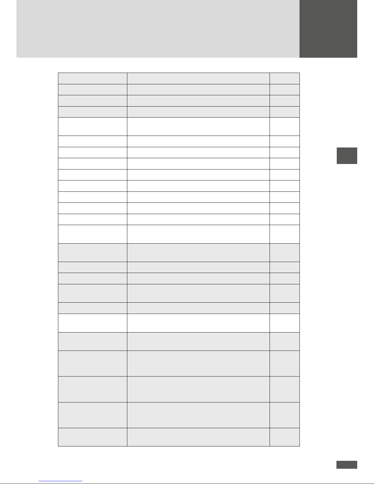
Function / Parameter Description Unit
Country Country setting selected during initial start-up -
Plant type Plant type selected during initial start-up -
Standard Grid connection selected during initial start-up
Vac min 1 Minimum admissible mains voltage (rst limit) V
t Vac min 1 Release time for minimum admissible mains voltage ms
Vac max 1 Maximum admissible mains voltage (rst limit) V

38
Function / Parameter Description Unit
t Vac max 1 Release time for maximum admissible mains voltage ms
Vac min 2 Minimum admissible mains voltage (second limit) V
t Vac min 2 Release time for minimum admissible mains voltage ms
Vac max 2 Maximum admissible mains voltage (second limit) V
t Vac max 2 Release time for maximum admissible mains voltage ms
Vac 10 min max Maximum admissible average value of the mains volt-
age over the last 10 minutes
V
Iac mean max Maximum permissible DC component in the mains
current
A
f min 1 Minimum admissible mains frequency (rst limit) Hz
t f min 1 Release time for minimum admissible mains frequency ms
f max 1 Maximum admissible mains frequency (rst limit) Hz
t f max 1 Release time for maximum admissible mains frequency ms
f min 2 Minimum admissible mains frequency (second limit) Hz
t f min 2 Release time for minimum admissible mains frequency ms
f max 2 Maximum admissible mains frequency (second limit) Hz
t f max 2 Release time for maximum admissible mains frequency ms
df/dt max Maximum admissible change of the mains frequency Hz/s
Ierr max Maximum admissible leakage current (effective value)
on the DC end
mA
Island detection Immediate grid disconnection when island operation
detected (Anti-Islanding)
Inactive/
on
Monit. ext. input The status signalling contact is congured for monitor-
ing an external input.
Inactive/
on
Restart delay Delay time before grid reconnection upon previous
failure-related grid disconnection.
s
Pac progression Maximum increase of the effective power during grid
reconnection upon previous failure-related grid disconnection.
%/min
Soft Start Maximum increase of the effective power at grid con-
nection. This gradient, if activated, is always effective,
as opposed to “Pac Progression” (even during restart
in the morning).
W/s
Mains check Additional mains check before connecting to the grid Inactive/
on
- Vac MC max Maximum admissible mains voltage V
- Vac MC min Minimum admissible mains voltage V
39
en
Function / Parameter Description Unit
- f MC max Maximum admissible mains frequency Hz
- f MC min Minimum admissible mains frequency Hz
- t MC Monitoring Duration of the mains check s
P(f)-Mode Frequency-dependent power reduction Inactive/
on
- f start Starting frequency Hz
- f stop Stop frequency Hz
- P(f) MC f max Maximum admissible mains frequency Hz
- P(f) MC f min Minimum admissible mains frequency Hz
- P(f) MC Vac max Maximum admissible mains voltage V
- P(f) MC Vac min Minimum admissible mains voltage V
- P(f) MC t monitoring Duration of mains check in P(f) mode s
- Reduction Reduction gradient %/Hz
- Re-increase Increase gradient to the maximum possible power
output (in % of rated output power Pac nom/min)
%/min
P(V)-Mode Output reduction dependent on grid voltage Inactive/
on
- Vac threshold Limit of grid voltage (average value) V
- Pac reduction Reduction gradient (% of Pac nom/min) %/min
- Pac recovery Increase gradient to the maximum possible power
output (% of Pac nom/min)
%/min
- Monitoring time Monitoring time s
Q-Mode
Reactive power mode: inactive (cosφ =1), cosφ,
cosφ(Pac), Q, Q( Vac) mode 1 or Q(Vac) mode 2
-
- Vac Lock Grid voltage-dependent on/off switch for the reactive
power modes cosφ and cosφ(Pac).
Inactive/
on
- Vac Lock-In High Value at which the reactive power mode is switched on.
Upper value at which the reactive power mode "Q(Vac)
mode 2" is switched on.
V
- Vac Lock-Out Low Value at which the reactive power mode is deactivated
(cosφ =1). Lower value at which the reactive power
mode "Q(Vac) mode 2" is switched off.
V
- QR 1 Fixed reactive power in reactive power mode "Q(Vac)
mode 2" (when grid voltage is too high; in % of
Pac nom)
%
- Vac Lock-Out High Upper value at which the reactive power mode Q(Vac)
mode 2" is deactivated (cosφ =1).
V

40
Function / Parameter Description Unit
- Vac Lock-In Low Lower value at which the reactive power mode "Q(Vac)
mode 2" is activated.
V
- QR 2 Fixed reactive power in reactive power mode "Q(Vac)
mode 2" (when grid voltage is too low; in % of
Pac nom)
%
- Pac Lock Active power-dependent on/off switch for the reactive
power modes cosφ and Q.
Inactive/
on
- Pac Lock-In Value at which the reactive power mode is activated. W
- Pac Lock-Out Value at which the reactive power mode is deactivated
(cosφ =1).
W
FRT Fault ride through function for dynamic grid support Inactive/
on
- K-Factor Reactive current static factor for voltage support with
reactive current during mains drops
-
Iac max Maximum admissible mains current (per phase) A
Pac max Maximum effective power to be fed W
S max Maximum apparent power to be fed. VA
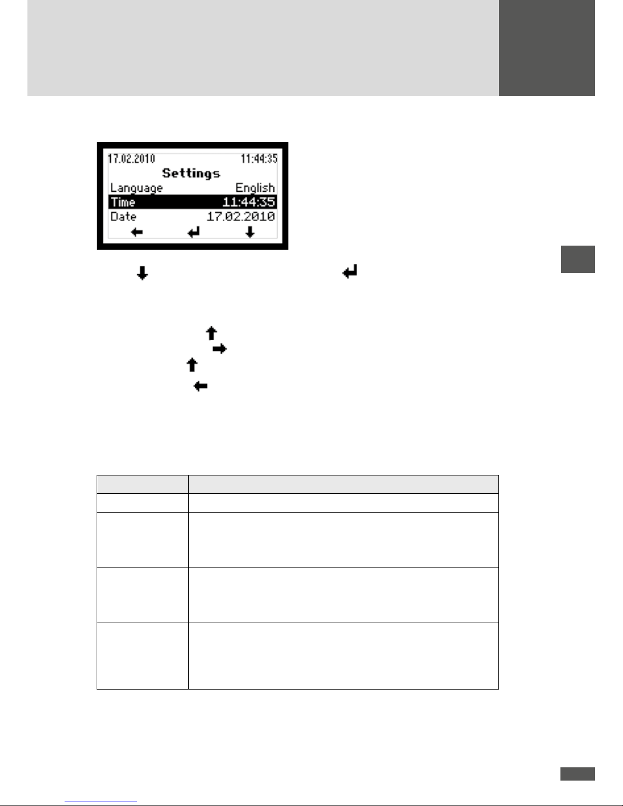
6.8 Settings
This menu can be used to set different communication parameters and monitoring functions. All settings can also be implemented with MaxTalk.
Parameter Description
Language Selection of the display language (German, English, French, Italian, or
Spanish). The display language can be selected independently of the
selected specic country settings.
Time Setting the internal clock
Date Setting the displayed date
Device address Denition of the device address between 1 and 249. If you connect
several inverters and accessory components to become one MaxComm
communication network, each device within the network must have an
individual address.
IP
Conguration of the Ethernet interface. Details see Section 5.3.Netmask
TCP Port
Status relay delay Setting the switching delay of the status signalling contact
Pinst tot Rated output of the PV generator (entry only possible in MaxTalk).
41
en
6.8.1 Implementing the settings
Use the button to select a parameter. Press the button to select a highlighted
parameter and switch into the editing mode to change it.
In the editing mode each individual number is changed.
Example: Using the button, the highlighted number can be increased. After editing
this number, use the
button to go to the next number which in turn can be incre-
ased using the
button.
Press the left button
to return to the Main menu.
6.8.2 Status relay
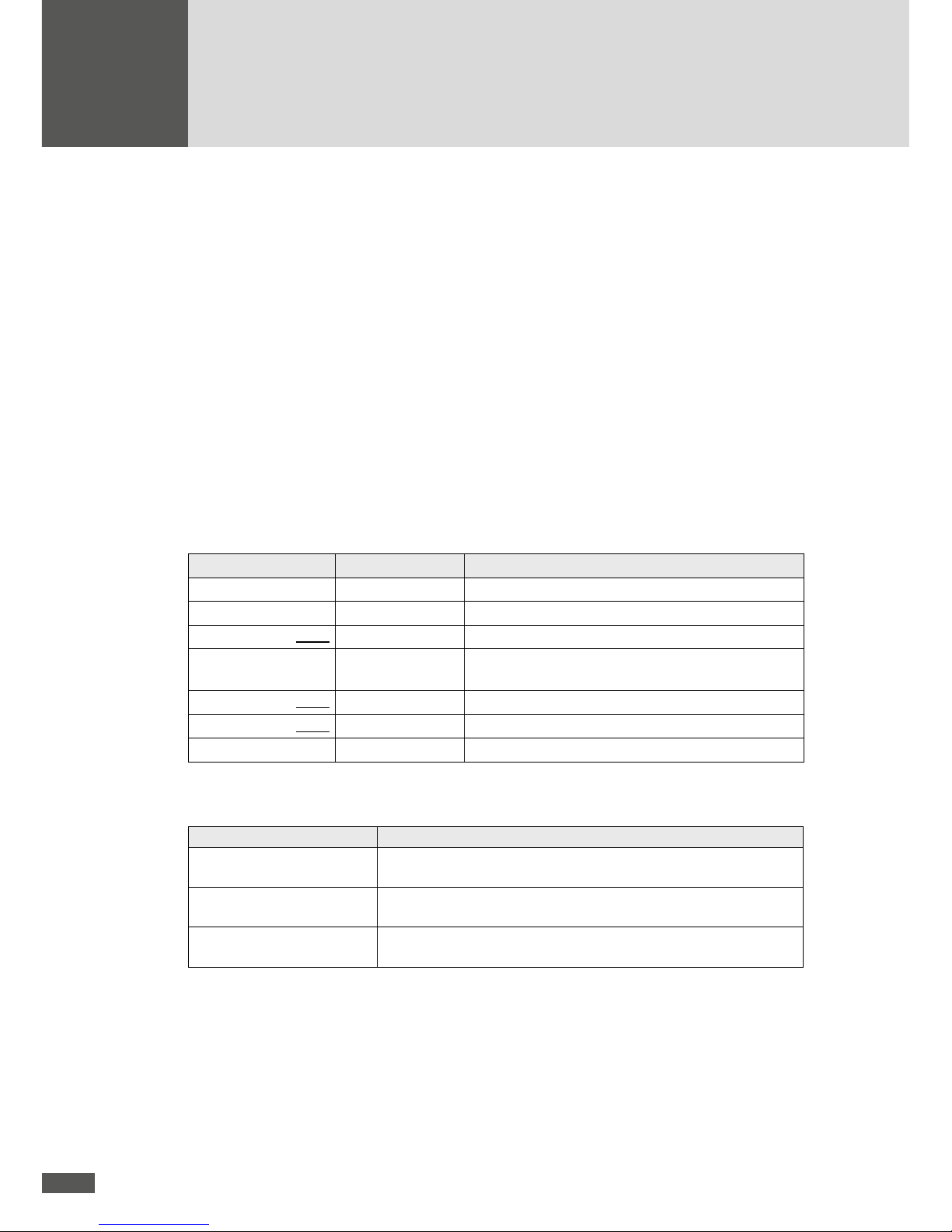
The functions of the status signalling contact can be adjusted. There are four different
functional settings.
Setting Description
Off The status signalling contact is always open.
Mains When the inverter starts mains operation, the status signalling contact
closes immediately and remains closed as long as the inverter is feeding
in. If the inverter is no longer feeding into the grid, the status signalling
contact opens after the adjustable delay time has expired.
Error If a warning, failure, or device error occurs with the inverter, the status
signalling contact closes after the adjustable delay time has expired (the
events are listed in 10.2 “Diagnosis & measures”). The status signalling
contact opens immediately when the error is no longer present.
On This setting is designed for controlling an external motorised AC discon-
nector, for example. When the inverter is switched on (sufciently high
DC input voltage), the status signalling contact closes. The status signalling contact will only re-open when the inverter is switched off (DC input
voltage too low).
The monitoring electronics are supplied by the PV generator, in other words during the
night and when the DC end is switched off, the status signalling contact is open.

42
6.9 Information
This menu contains the following information:
Device type
Serial number
Firmware version
Status message and two-digit number code (if a device error occurs)
Warning (alternating display if several warnings are active at the same time)
Date of initial start-up
Accumulated operating hours
Date
Time
Use the
and keys to move through the menu. Press the left button to return
to the Main menu.
6.10 Auto Test according to DK 5940
During mains operation, the Auto Test procedure according to DK 5940 (only for country
setting “Italy”) varies the trigger threshold for AC voltage and frequency monitoring linearly with a ramp of ≤ 0.05Hz/s and/or ≤ 0.05Vn/s (Vn = 230Vac). This way, at some
point during the test, the threshold will coincide with the current measured value, leading
to triggering of the monitoring intervention. After each test step the values of the trigger
thresholds, delay times, current measured frequency and AC voltage values, and the
standard threshold trigger value are displayed.
6.10.1 Start Auto Test
The Auto Test can be activated only if there is sufcient irradiance, the inverter is connected to the grid, and is in feed mode.
1. Wait until the inverter has connected to the grid.
2. Select the “Auto Test” menu item in the Main menu.
3. Answer the question whether the Auto Test should be executed with YES.
4. The Auto Test now runs automatically.
NOTE
If an error occurs during the test or the irradiance is too low, the Auto Test is aborted
and the message “Auto Test aborted” appears in the display together with an associated error message.

43
en
6.10.2 Procedure
Maximum voltage
The set voltage monitoring threshold Vac max is displayed.
The threshold value is decremented linearly until it reaches the current mains voltage
value and grid monitoring is triggered.
The trigger value, the trigger time, the current value, and the default value of voltage
monitoring (Vac max) are displayed.
Minimum voltage
The set voltage monitoring threshold Vac min is displayed.
The threshold value is incremented linearly until it reaches the current mains voltage
value and grid monitoring is triggered.
The trigger value, the trigger time, the current value, and the default value of voltage
monitoring (Vac min) are displayed.
Maximum frequency
The set frequency monitoring threshold f max is displayed.
The threshold value is decremented linearly until it reaches the current mains fre-
quency value and grid monitoring is triggered.
The trigger value, the trigger time, the current value, and the default value of frequency
monitoring (f max) are displayed.
Minimum frequency
The set frequency monitoring threshold f min is displayed.
The threshold value is incremented linearly until it reaches the current mains fre-
quency value and grid monitoring is triggered.
The trigger value, the trigger time, the current value, and the default value of frequency
monitoring (f min) are displayed.
After the Auto Test is complete, the inverter returns to normal operation.
44
7 Operating status
7.1 Status messages and status LED
The status message in the graphics display describes the current operating status of the
inverter. Each inverter status message belongs to one of the ve possible operating statuses. The status LED always displays one of these operating statuses through a variety
of colours. In addition to the status messages, the inverter can also display warnings.
Warnings result from device errors or external failures which, however, do not affect the
mains operation of the inverter. Losses of yield are possible, however.
Warnings have no relation to the operating status and are displayed on the graphics display alternately with the current status message.
The status messages of the “Failure”, “Error”, and “Blocked” operating statuses, as well
as the warnings, usually require certain measures to be taken, see Section 8.2.
LED status Operating status Description
Off -
Inverter is switched off → grid disconnection
Flashing green – – – Booting
Inverter starts → grid disconnection
Green
Mains operation Grid feed-in (normal operation)
Flashing
orange – – –
-
Warning → no grid disconnection
Orange
Failure
External failure → grid disconnection
Red
Error
Internal device error → grid disconnection
Flashing red – – – Blocked
Inverter is blocked → grid disconnection
7.2 Booting
Status message Description
Irradiance too low The solar irradiation or rather the available output is too low for
mains operation.
Startup… The inverter checks the internal hardware and software
components before connecting to the grid.
Restart delay The inverter has disconnected itself from the grid and is
delaying re-connection to the grid.
45
en
7.3 Mains operation
Status message Description
Mains operation The inverter has been switched to the grid and is feeding power
into the grid.
Maximum power The inverter limits the output power to the maximum permissible
level. Limiting the power can occur when the PV generator has
been oversized or in the event of high irradiation.
Idc limitation The inverter limits the DC input current to the maximum permis-
sible value. This can occur if the PV generator was designed so
that the current in the MPP is higher than the maximum permissible DC current of the inverter.
Iac limitation The inverter limits the fed-in mains current to the maximum
permissible value. This can occur in response to major uctuations
in irradiation, low mains voltage or due to an over-dimensioned PV
generator.
Restart limitation The inverter increases the active power after the conclusion of an
external limitation with a dened progression (Pac progression
and/or Soft Start).
Frequency limitation The inverter temporarily limits the active power due to an active
frequency-dependent reduction in power - P(f) mode.
External limitation The output power of the inverter is limited by a remote command.
7.4 Communications activity
The communications activity of the inverter is displayed via two different symbols on the
graphics display.
Symbol Description
This symbol is displayed when the inverter sends or receives data
(via RS485 or Ethernet).
This symbol appears when there is an Ethernet connection (corresponds with
the “Link” display on network cards).

46
8 Troubleshooting
SolarMax Produktions GmbH delivers only SolarMax inverters which have stood up to our
extensive quality testing regime. Moreover, each inverter is subjected to several hours of
endurance testing under full-load conditions.
If, despite this, your PV plant suffers a failure or an error we recommend these procedures:
DANGER
Work on the PV plant must be performed by qualied electricians only.
1. Check whether the inverter and PV generator have been installed correctly. Check the
cable connections using the instructions and information contained in the “Installation” section of this manual.
2. Determine the cause of the failure by checking the message in the graphics display.
Section 10.2 “Diagnosis & measures” explains possible ways of correcting failures.
If you cannot correct the failure using the recommended measures, or you are not sure
what sort of error is involved, please contact our SolarMax Service Centre.
8.1 SolarMax Service Center
If you have technical questions or difculties, our Service Center would be happy to help
you. If you have questions about failures, please provide us with the following details:
Device type
Serial number S/N
Installation location
Information about the failure you are experiencing (status message, etc.)
Availability
The contact details of the SolarMax Service Center can be found on the back of this
instruction manual.
SolarMax Produktions GmbH
Zur Schönhalde 10
D-89352 Ellzee

47
en
8.2 Diagnosis & measures
The following tables describe possible measures for remedying failures. If the measures suggested do not correct the failure, please contact the SolarMax Service Centre
immediately.
8.2.1 General troubleshooting
Cause Steps
The display remains blank DC disconnector Q1 is
switched off.
Switch on DC disconnector
Q1.
Irradiation too low. Wait until the irradiation is
sufcient.
Strings disconnected. Check PV generator and
correct disconnection.
Internal failure. Notify the SolarMax Service
Centre.
The PV generator is connected
incorrectly (plus and minus
connections have been mixed
up).
Connect the PV generator
properly.
8.2.2 Warnings
Warning Cause Measure
Failure fan A fan is defective or dirty. Contact the SolarMax Service
Centre.
Temperature limitation The feed-in power has been
temporarily reduced to
limit the temperature of the
inverter.
Clean the fan grids and
improve ventilation in the
operations room.
Failure temp. sensor A temperature sensor in the
inverter has failed.
Contact the SolarMax Service
Centre.
Burst error The inverter disconnected
from the grid ve times or
more on the same day. The
warning is displayed for the
remainder of the day. The error
counter will be reset when
the system is restarted in the
morning.
Check your plant’s status logger in MaxWeb xp (if present)
or check the grid parameters.
If this happens repeatedly,
contact our SolarMax Service
Centre.

48
Warning Cause Measure
RTC error The RTC (real-time clock) in
the inverter is malfunctioning,
the date and time have been
reset.
If this problem happens frequently, contact the SolarMax
Service Centre. Set the time
and date correctly.
Flash error A ash error has occurred.
Inverter mains operation continues to be guaranteed.
Contact the SolarMax Service
Centre.
Firmware mismatch The rmware versions of the
inverter controllers do not
match.
Contact the SolarMax Service
Centre.
8.2.3 Failures
Status message Cause Measure
Vdc too high (VDC3, VDC2,
VDC1)
The DC input voltage at the
specied inverter DC connection is too high.
Switch off the DC disconnector Q1 immediately and
disconnect the PV generator
from the inverter. Check
the dimensioning of the PV
generator.
No mains
No mains BP
There is no mains voltage
or the AC supply has been
interrupted.
Check the AC supply.
Mains error
Mains error BP
The grid has been switched
off.
If this problem continues to
occur, contact the responsible
grid operator.
Frequency too high
Frequency too high BP
The mains frequency is
outside of the f max 1 or f max
2 limit values.
Frequency too low
Frequency too low BP
The mains frequency is
outside of the f min 1 or f min
2 limit values.
Vac too high (L1 L2 L3)
Vac too high BP (L1 L2 L3)
The mains voltage at the
specied phase is outside of
the Vac max 1 or Vac max 2
limit values.
Vac too low (L1 L2 L3)
Vac too low BP (L1 L2 L3)
The mains voltage at the
specied phase is outside of
the Vac min 1 or Vac min 2
limit values.

49
en
Status message Cause Measure
Vac 10min too high (L1 L2 L3)
Vac 10min too high BP
(L1 L2 L3)
The maximum 10-minute
average value of the mains
voltage ( Vac 10 min max.)
at the specied phase is too
high.
If this problem continues to
occur, contact the responsible
grid operator.
df/dt too high The change in the mains
frequency per second has
exceeded the maximum
admissible value df/dt max.
Insulation fault DC
Insulation fault DC BP
The insulation resistance of
the PV generator against earth
is too low.
Check the PV generator.
Ierr too high
Ierr too high BP
The DC leakage current has
exceeded the admissible
absolute limit value lerr max.
Ierr step too high
Ierr step too high BP
The DC leakage current has
exceeded the admissible step
value.
L and N interchanged A phase and the neutral
conductor are incorrectly connected (interchanged).
Connect the AC supplies
correctly.
Error DC polarity One or more DC connections
are connected incorrectly
(incorrect polarity).
Connect the DC supplies
correctly.
Error ext. input 1 The external grid monitoring
and/or remote shutdown has
disconnected the inverter from
the grid.
If this problem continues to
occur, contact the responsible
grid operator.
8.2.4 Error
Status message Cause Measure
Device error (+ error code) An internal error has occurred
in the inverter.
Check the two-digit error code
displayed and contact the
SolarMax Service Centre.
8.2.5 Blockings
Status message Cause Measure
External blocking There is a 0% command from
MaxRemote (coming from the
grid operator).
None. Wait until the grid
operator suspends the
blocking of the inverter via
MaxRemote.

50
Status message Cause Measure
Program Firmware The inverter rmware is cur-
rently being updated.
The inverter automatically
resumes mains operation
once the rmware update is
complete.
9 Maintenance
SolarMax inverters are basically maintenance-free. However, in order to ensure perfect
operation over the course of several years, in addition to regular controls of the operating
and yield data via the inverter display or remote monitoring, we also recommend performing the simple maintenance work described below at regular intervals. The maintenance intervals must be set keeping the ambient conditions in mind (especially exposure
to dust).
The following checks can be performed by the plant operator. If you discover problems
while performing these checks, contact the electrician in charge of maintenance or our
SolarMax Service Centre.
Functional check of the inverter using the graphics display
On-site check of visible traces of wear and tear (damage, rain, snow, rodents, etc.)
Cleaning and check of plant room
Cleaning the fan screens
10 Disposal
Please dispose of the inverter at the end of its service life in compliance with the disposal
regulations then valid where it is installed. You can also return the inverter at your own
cost for professional disposal to SolarMax Produktions GmbH.
51
en
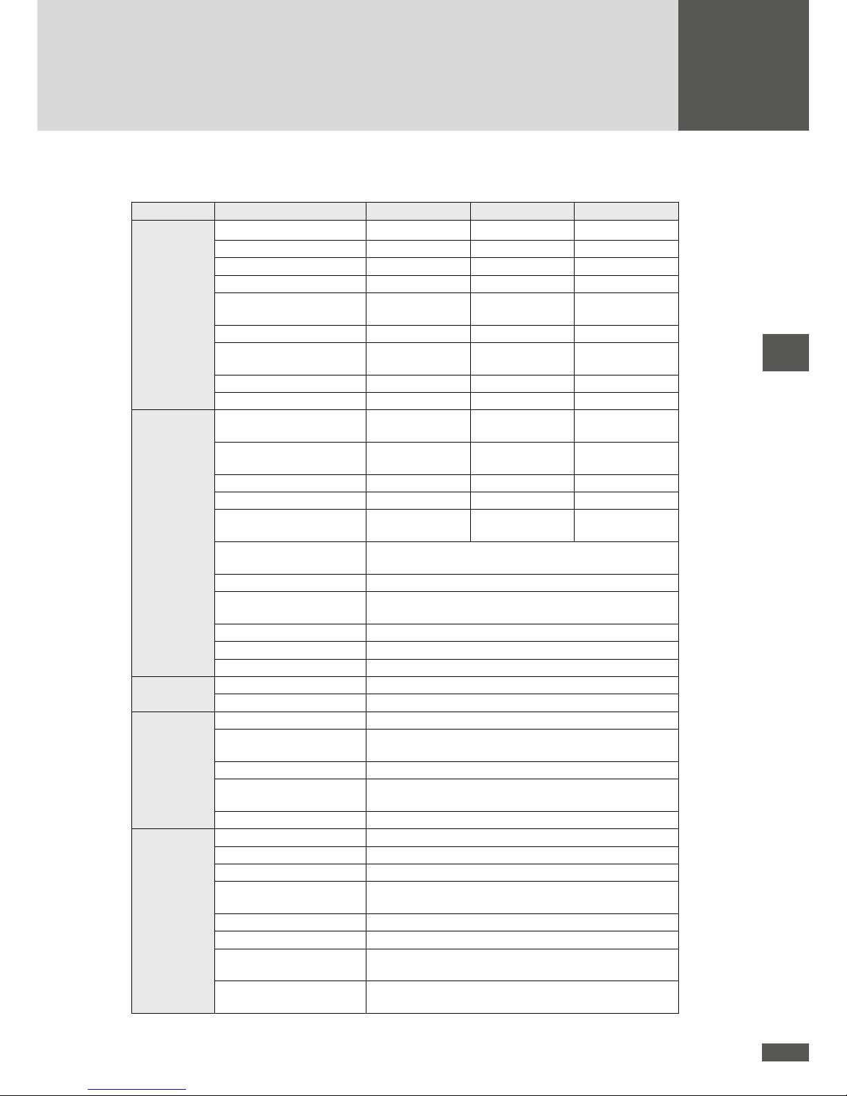
11 Technical data
6MT2 8MT2 10MT2
Input
values
MPP voltage range
1)
340… 750 V
2)
300… 750 V
2)
290… 750 V
2)
Minimum DC voltage 250 V 250 V 250 V
Maximum DC voltage 900 V 900 V 900 V
Maximum DC current 1 x 9 A / 1 x 9 A 1 x 18 A / 1 x 9 A 2 x 18 A
Maximum DC short-circuit
current
1 x 9 A / 1 x 9 A 1 x 18 A / 1 x 9 A 2 x 18 A
Number of MPP trackers 2 2 2
Max. PV generator output
per MPP tracker
5 000 W MPPT1: 9 000 W
MPPT2: 5 000 W
9 000 W
String connections 1 x 2 / 1 x 1 1 x 2 / 1 x 1 2 x 2
Connection type MC 4 MC 4 MC 4
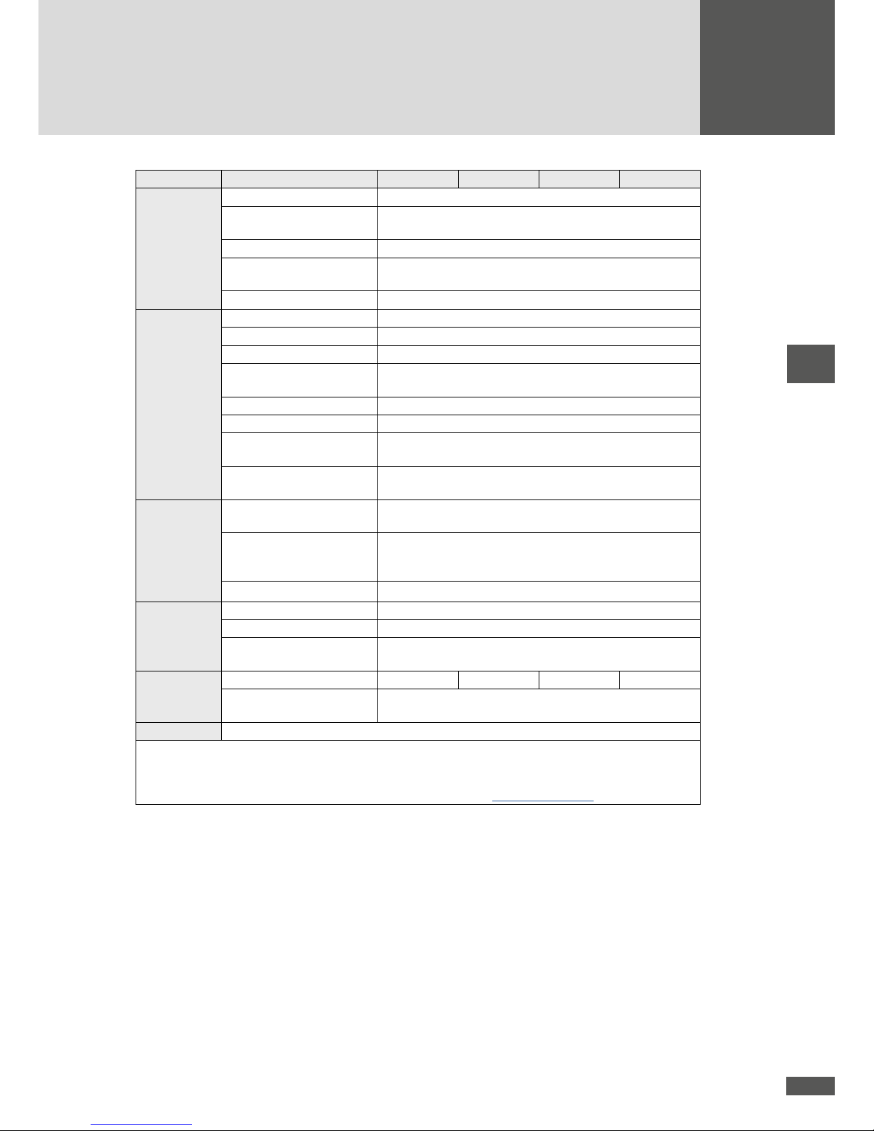
Output values Rated output power at
cosφ = 1
6 000 W 8 00 0 W 10 000 W
Maximum apparent output
power
6 000 VA 8 000 VA 10 0 00 VA
Nominal mains voltage 3 x 400 V 3 x 400 V 3 x 400 V
Maximum AC current 3 x 9 A 3 x 12 A 3 x 16 A
Maximum AC short-circuit
current
42 A
peak
42 A
peak
42 A
peak
Mains nominal frequency
/ range
50 Hz / 45 Hz…55 Hz
Power factor cosφ
adjustable from 0.8 overexcited to 0.8 underexcited
Distortion factor at rated
output power
< 3 %
Connection type Connector (locking)
Grid connection three-phase (3 /N / PE)
Power input at night 0 W
Efciency Max. efciency 98.0 %
European efciency 9 7.5 %
Ambient
conditions
Protection type IP65
Ambient temperature range
(at rated output power)
−20 °C…+60 °C (−20 °C…+50 °C)
Relative humidity 0…100 % (condensation)
Maximum altitude above
sea level
2 000 m
3)
Noise emissions (↔ 1.5 m)
51 dB(A) fan off / 58 dB(A) fan on
Conguration Display Graphic LC display with backlight and status LED
DC disconnector integrated (cat. DC-21 or higher)
Circuit type two-stage, transformerless
Data logger Data logger for energy yield, peak output, and operating dura-
tion for the last 31 days, 12 months and 10 years
Fault current monitoring internal, AC/DC sensitive
Casing Aluminium
Overvoltage conductor DC Requirement class C (VDE 0675-6) and/or type 2
(EN 616 43 -11)
Overvoltage conductor AC Requirement class D (VDE 0675-6) and/or type 3
(EN 616 43 -11)

52
6MT2 8MT2 10MT2
Standards &
guidelines
EMC EN 61000-3-2 / EN 61000-3-3 / EN 61000-3-11 / EN 61000-
3-12 / EN 61000-6-2 / EN 61000-6-3
Grid connection
2)
VDE-AR-N 4105 / VDE 0126-1-1 A1:2012 / BDEW MS-
Richtlinie / CEI 0-21 / CEI 0-16 / RD 661 / RD 1699 / G59/3 /
G83/2 / PPC Guide / C10/11 / EN 50438 / AS 4777
Device safety
IEC / EN 62109-1/-2
Interfaces Data communication RS485 / Ethernet
Status signalling contact M12 connector with relay as N/C contact / N/O contact
Connection of external grid
monitoring
M12 connector
Weight &
dimensions
Weight 39 kg 39 kg 39 kg
Dimensions in mm
(W x H x D)
550 x 750 x 200
Warranty Standard 5 years / extension to 10, 15, 20, or 25 years possible
1) for AC rated power output
2) max. 700 V with external power limitation
3) contact us if the installation location is at a higher level
4) certicates are not available for all models. Details can be found at www.solarmax.com
13MT2 15MT2 13MT3 15MT 3
Input
values
MPP voltage range
1)
370… 750 V2)430… 750 V2)280… 750 V2)320… 750 V
2)
Minimum DC voltage 250 V 250 V 250 V 250 V
Maximum DC voltage 900 V 900 V 900 V 900 V
Maximum DC current 2 x 18 A 2 x 18 A 3 x 16 A 3 x 16 A
Maximum DC short-circuit
current
2 x 18 A 2 x 18 A 3 x 16 A 3 x 16 A
Number of MPP trackers 2 2 3 3
Max. PV generator output
per MPP tracker
9 000 W 9 0 00 W 9 00 0 W 9 000 W
String connections 2 x 2 2 x 2 3 x 2 3 x 2
Connection type MC 4 MC 4 MC 4 MC4
Output values Rated output power at
cosφ = 1
13 000 W 15 000 W 13 00 0 W 15 000 W
Maximum apparent output
power
13 000 VA 15 000 VA 13 00 0 VA 15 00 0 VA
Nominal mains voltage 3 x 400 V 3 x 400 V 3 x 400 V 3 x 400V
Maximum AC current 3 x 20 A 3 x 22 A 3 x 20 A 3 x 22 A
Maximum AC short-circuit
current
42 A
peak
42 A
peak
42 A
peak
42 A
peak
Mains nominal frequency
/ range
50 Hz / 45 Hz…55 Hz
Power factor cosφ
adjustable from 0.8 overexcited to 0.8 underexcited
Distortion factor at rated
output power
< 3 %
Connection type Connector (locking)
Grid connection three-phase (3 /N / PE)
Power input at night 0 W
Efciency Max. efciency 98.0 %
European efciency 9 7.5 %
53
en
13MT2 15MT2 13MT3 15MT 3
Ambient
conditions
Protection type IP65
Ambient temperature range
(at rated output power)
−20 °C…+60 °C (−20 °C…+50 °C)
Relative humidity 0…100 % (condensation)
Maximum altitude above
sea level
2 000 m
3)
Noise emissions (↔ 1.5 m)
51 dB(A) fan off / 58 dB(A) fan on
Conguration Display Graphic LC display with backlight and status LED
DC disconnector integrated (cat. DC-21 or higher)
Circuit type two-stage, transformerless
Data logger Data logger for energy yield, peak output, and operating dura-
tion for the last 31 days, 12 months and 10 years
Fault current monitoring internal, AC/DC sensitive
Casing Aluminium
Overvoltage conductor DC Requirement class C (VDE 0675-6) and/or
type 2 (EN 61643-11)
Overvoltage conductor AC Requirement class D (VDE 0675-6) and/or
type 3 (EN 61643-11)
Standards &
guidelines
EMC EN 61000-3-2 / EN 61000-3-3 / EN 61000-3-11 / EN 61000-
3-12 / EN 61000-6-2 / EN 61000-6-3
Grid connection
2)
VDE-AR-N 4105 / VDE 0126-1-1 A1:2012 / BDEW MS-
Richtlinie / CEI 0-21 / CEI 0-16 / RD 661 / RD 1699 / G59/3 /
G83/2 / PPC Guide / C10/11 / EN 50438 / AS 4777
Device safety
IEC / EN 62109-1/-2
Interfaces Data communication RS485 / Ethernet
Status signalling contact M12 connector with relay as N/C contact / N/O contact
Connection of external grid
monitoring
M12 connector
Weight &
dimensions
Weight 39 kg 39 kg 42 kg 42 kg
Dimensions in mm
(W x H x D)
550 x 750 x 200
Warranty Standard 5 years / extension to 10, 15, 20, or 25 years possible
1) for AC rated power output
2) max. 700 V with external power limitation
3) contact us if the installation location is at a higher level
4) certicates are not available for all models. Details can be found at www.solarmax.com

54
11.1 Country-specic settings
The factory’s default settings for different countries can be viewed in the technical
information “Country-specic functions and parameters - Factory settings”. This document can be downloaded from our website at: www.solarmax.com/en/downloads/
string-inverters/mt-series.
11.2 Efciency curve SolarMax 15MT3
Efciency η [%]
Standardised output Pac/Pac ma x [%]
11.3 Temperature-dependent output reduction (power derating)
SM6MT2 / SM8MT2 / SM10MT2
Standardised output Pac/Pac ma x
Ambient temperature [°C]

55
en
SM13MT2 / SM13MT3
Standardised output Pac/Pac ma x [%]
Ambient temperature [°C]
SM15MT2 / SM15MT3
Standardised output Pac/Pac ma x [%]
Ambient temperature [°C]

56
12 Accessories and options
Accessory/option Description
Ma xTalk 2 Free communication and service software for local monitoring of
the PV plant.
MaxTalk 2 Pro
Professional version of MaxTalk for the conguration of inverters.
The required “SolarMax MT series - Parameter conguration using
MaxTalk 2 Pro” operating manual can be downloaded from our
website; www.solarmax.com (“Downloads” area).
MaxWeb xp MaxWeb xp is a data logger, monitoring unit, and web server
in one. For all those who want to have their PV plant monitored
and checked reliably and professionally, MaxWeb xp is the ideal
solution.
MaxWeb Portal The MaxWeb Portal is the ideal complement to the MaxWeb xp
data logger. When using the MaxWeb Portal, you can access the
data of your PV plant from anywhere on the Internet. The MaxWeb
Portal provides a wide variety of graphic and chart display options
for the evaluation of your PV plant’s operating parameters.
MaxMonitoring Using the free MaxMonitoring software, you can display the per-
formance data of your photovoltaic system at any time from home.
MaxMonitoring is available for PC, MacOS and Linux and also as
an app for Android and iOS.
MaxMeteo Unit recording irradiation data and cell temperature of PV modules
MaxCount Unit recording meter gures with S0 interface
MaxDesign Free software for determining the size of PV plants.
You can nd further information on our website at www.solarmax.com.
13 Warranty
General Terms of Guarantee for SolarMax Products
SolarMax Productions GmbH (herafter SOL ARMAX) guarantees the correct function and absence of
defects of your SolarMax tools for a particular, device -specic duration of guarantee. This duration
of guarantee can be prolonged by an extension of guarantee according to these Terms of Guarantee.
This manufacturer’s guarantee exists in addition to legal warranty obligations of the vendor. In case
of a content overlap, the claim under the manufacturer’s guarantee takes precedence, to the extent
permitted by law, over the claim from warranty.

57
en
For the assertion of warranty claims please contact your vendor.
1. Basic Guarantee BASIC
The services of the Basic Guarantee are only provided free of charge in countries released by
SOLARMAX at the time of installation. Please clarify this with your dealer. You will nd a current
list of these countries in the appendix or on our homepage. On request we are happy to send you
this list.
a) Duration of Guarantee BASIC
String Inverters:
60 months starting from purchase date, but max. 72 months after delivery of the device by
SOLARMAX
Central Inverters:
Series C/S/TS/TS-SV: 24 months from purchase date, but max. 30 months after delivery of
device by SOLARMA X
Series RX: 60 months from purchase date, but max. 66 months after delivery of device by
SOLARMAX
Accessories:
24 months from purchase date, but max. 30 months after delivery of device by SOLARMAX
Junction-Box 32HT2: 60 months from purchase date, but 72 months after delivery of device by
SOLARMAX
Deviating written conrmation from SOLARMAX have priority.
b) Scope of Guarantee BASIC
If a device shows a defect or malfunction within the duration of guarantee and if the conditions
for the assertion of warranty as dened below are met, the device or device parts will be repaired
or replaced by SOLARMAX free of charge at its discretion within an appropriate period of time, as
shown below, provided that this is not disproportionate or impossible.
Free Replacement: This contains the provision of equivalent replacement devices or parts, which
can be dispatched step by step against return of the defect devices or device parts or can be also
delivered by order.
Free On-Site-Replacement: This contains material cost as well as labor and travel expenses of
SOLARMAX staff or staff authorized by SOLARMAX, insofar as it was send to the operation site
by SOLARMAX.
Further-reaching claims, especially claiming the replacement of direct and indirect damages,
founded by the defect of the device or cost incurred by the implementation and removal or lost
prot, are not covered by this guarantee.
2. Assurance of Repair and Replacement
SOLARMAX will provide repair material and replacement devices during the duration of guarantee
in its discretion.
If repair material or replacement devices for particular devices are not available anymore, the following applies:

58
SOLARMAX is authorized to install the device, which needs to be replaced, with a comparable
device with an equivalent or higher performance.
Necessary technical adjustments of the replacement device for the installation of such a replacement device are covered by the guarantee for expenditure of time and material to the extent of up to
10 % of the list price of the replacement device.
Not covered by the guarantee are, if need be, a required replacement and a connection of peripheral
devices as well as, if need be, required adjustments of surrounding devices of an inverter (such as
supply cord, ventilation and safety devices).
SOLARMAX does its level best to minimize the extent of adjustment.
If there is no replacement material available at a reasonable expense, SOL ARMAX is authorized to
replace the defect device. In this case the above mentioned terms of replacement are applicable.
3. Duration of Guarantee for Device Repair/ Device Replacement
In case of repair or replacement of devices within the scope of the guarantee, the remaining duration
of guarantee of the original device applies to the repaired / replaced device.
4. Exclusion of Guarantee Services
Especially in following cases the guarantee claim is cancelled:
In the event of transport damage or external inuences
In the event of interference, changes, repairs by non-SOLARMA X-authorized staff or on one’s
own
In the event of inappropriate use, incorrect operation and installation
In the event of neglecting operating, installation and maintenance instructions
In the event of non-compliant surrounding conditions (such as lack of ventilation, humidity, dust
pollution, etc.)
In the event of higher force (such as lightning, overvoltage, water damage, re etc.)
Not covered by the guarantee are wear parts, especially fuses and overvoltage protection
5. Assertion of Guarantee
For the assertion of the guarantee the SOLARMAX hotline must be contacted by phone or in written
form and their instructions must be followed carefully.
You will nd the Hotline number for your country on our homepage.
Please hold the series number, the article description, a short description of the defect and the
purchase receipt ready.
Transactions in order to solve guarantee cases carried out by the buyer without the coordination
with and approval by SOLAR MAX will not be compensated.
In case of neglecting this procedure SOLARMAX reserves the right to decline the delivery of of the
guarantee service.
6. Exclusion of Guarantee
SOLARMAX reserves the right to temporarily or nally exclude the guarantee, if the parameters of
the plant do not allow a proper function of the devices (e.g. in the event of a parameter as set out
in number 4)
The exclusion of guarantee can be cancelled in accordance with SOLARMAX.

59
en
Therefore it is necessary to have a written conrmation by SOLARMAX, in order to restart the
guarantee terms.
7. Guarantee Extension
For devices with the Basic Guarantee BASIC the duration of guarantee can be prolonged by
purchasing a guarantee extension within the following time periods. An extension for specic
devices can be purchased on the basis of limited services. The extensions being available per
device can be found on our homepage. The purchase of a guarantee extension will be conrmed by
SOLARMAX with a Guarantee Certicate (Series Number of Product).
In case of a replacement this certicate will not be adjusted to the new series number. In this way
the guarantee extension stays unaffected.
a) Time Limit for entry into Guarantee Extension
String Inverters / J unction-Box 32HT2: The extension of the guarantee can be purchased within 60
months starting from purchase date, but within max. 72 months after delivery of the device by
SOLARMAX.
Central Inverters: The extension of the guarantee can be purchased within 3 months starting from
purchase date, but max. 12 months after delivery of the device by SOLARMAX
b) Scope of the Guarantee Extension
The Scope of the Guarantee Extension contains all services of the Basic Guarantee BASIC.
c) Conclusion of a Guarantee Extension
In order to purchase a Guarantee Extension, it is necessary to fully complete and hand in a Guarantee Extension form.
The Guarantee Extension is completed with a written conrmation by SOLARMAX, the receipt of the
Guarantee Certicate and the payment by the customer.
Deviating written conrmation from SOLARMAX have priority.
8. Conditions after the Extension of the Guarantee
The cost for repair and replacement after the extension of the guarantee period will be charged at
cost. SOLARMAX ensures the repair and replacement ability beyond the guarantee period at its
own discretion.
9. Applicable Law, Place of Jurisdiction
The Law of the Federal Republic of Germany is applicable, Place of Jurisdiction shall exclusively be
Augsburg / Germany, as far as this is permitted by law.
Appendix Country List:
Austria, Belgium, Bulgaria, Czech Republic, Denmark, France, Germany, Greece, Italy, Liechstenstein, Luxembourg, Netherlands, Portugal, Slovakia, Slovenia, Spain, Sweden, Switzerland, United
Kingdom
(Issued 10/2015 – subject to modications)

2015 / 10 en
SolarMax Service Center
Please refer to our website for contact details:
www.solarmax.com/en/services-warranty
www.solarmaxservice.com
Hotline:
DE + 49 3733 5 07840
CH + 41 315281165
ES + 3 4 93 220 3859
GB + 4 4 20 380 80346
IT + 39 04185200 76
FR + 33 820 420 684
Fax + 49 3733 50784 99
Mail
hotline@solarmax.com
 Loading...