


EN
Manual V.4.2.0
Solar-Log 50
1

Publisher:
Solare Datensysteme GmbH
Fuhrmannstr. 9
72351 Geislingen-Binsdorf
Germany
International support
Tel.:+49 7428 9418 -640
Fax:+49 7428 9418 -280
e-mail: support@solar-log.com
Italy
Technical support: +39 0471 631032
e-mail: italy-support@solar-log.com
France
Technical support: +33 97 7909708
e-mail: france-support@solar-log.com
Switzerland
Technical support: +41 565 355346
e-mail: switzerland--support@solar-log.com
United States
Technical support: +1 203 702 7189
e-mail: usa-support@solar-log.com
2

Table of Contents
1 Introduction .................................................................................................................... 7
2 Safety information ....................................................................................................... 8
2.1 Hazard Classes .............................................................................................................................................................. 8
3 Electric current ..............................................................................................................9
4 Package Contents and Installation ...................................................................... 10
5 Solar-Log 50 Connections ........................................................................................11
5.1 Top Connections Solar-Log 50 .............................................................................................................................. 11
5.2 Bottom Connections Solar-Log 50 ..................................................................................................................... 12
6 Connector Assignments and Wiring ....................................................................13
6.1 Notes on wiring the connections ......................................................................................................................... 13
6.2 2 x RS485 (A/B) or 1 x RS422 ............................................................................................................................... 14
7 Connecting the inverters .......................................................................................... 15
7.1 Switch o the inverters and the Solar-Log™. .................................................................................................. 16
8 Connecting accessories ............................................................................................17
8.1 External power meter ............................................................................................................................................... 17
8.1.1 External power meters/accumulating meters .................................................................................................. 18
9 Other connections ......................................................................................................19
9.1 USB .................................................................................................................................................................................. 19
3

10 Installation .................................................................................................................... 20
10.1 Connect the Solar-Log™ to a network / PC. ................................................................................................... 20
10.2 Initial set up of the Solar-Log 50 ......................................................................................................................... 21
11 Go to the Main Menu. ................................................................................................ 22
11.1 Operating the Main Menu of the Solar-Log™ ................................................................................................. 25
11.1.1 Control elements ........................................................................................................................................................ 26
11.2 Explanations of the names in the main menu. ............................................................................................... 27
11.2.1 Header bar .................................................................................................................................................................... 27
11.2.2 Left-side navigation menu ...................................................................................................................................... 27
11.2.3 Configuration Page .................................................................................................................................................... 27
11.2.4 Login Section Menu ................................................................................................................................................... 28
11.2.5 Hide arrow.....................................................................................................................................................................30
11.2.6 New Firmware .............................................................................................................................................................30
11.3 Setting up of the Solar-Log™ with the configuration assistant.............................................................. 32
11.3.1 Solar-Log 50 Manual Configuration .................................................................................................................... 37
12 Main menu .....................................................................................................................38
12.1 Virtual LCD Display ................................................................................................................................................... 38
13 Configuration Menu ...................................................................................................39
13.1 Configuring network settings ............................................................................................................................... 39
13.1.1 Ethernet .........................................................................................................................................................................40
13.1.2 Proxy ............................................................................................................................................................................... 42
13.2 Internet Configuration ............................................................................................................................................. 43
13.2.1 Portal ...............................................................................................................................................................................43
13.3 Configuring connected devices ........................................................................................................................... 45
13.3.1 Device definition .........................................................................................................................................................46
13.3.2 Device Detection ........................................................................................................................................................48
13.3.3 Configuring devices ..................................................................................................................................................49
13.3.4 Configuring inverters ................................................................................................................................................49
13.3.5 Generation Information on PAC Correction Factor ......................................................................................50
13.3.6 Configuring power meters ....................................................................................................................................... 51
13.3.7 Configure the battery ............................................................................................................................................... 52
13.3.8 Module Fields, Power Output and Descriptions............................................................................................. 52
13.4 Feed-in management (with an active license)............................................................................................... 54
13.4.1 Plant parameters ........................................................................................................................................................ 54
13.4.2 Active power ................................................................................................................................................................54
13.4.3 Active power deactivated ....................................................................................................................................... 55
13.4.4 70% fixed reduction .................................................................................................................................................. 55
13.4.5 70% Fixed reduction with the calculation of self-consumption ..............................................................56
13.4.6 Adjustable reduction ................................................................................................................................................ 56
13.4.7 Adjustable Reduction with the Calculation of Self-Consumption........................................................... 57
13.4.8 Fixed reduction in watts .......................................................................................................................................... 57
13.4.9 Fixed reduction in watts with the calculation of self-consumption ....................................................... 57
4

13.4.10 Percentage of consumption for an adjustable reduction .......................................................................... 58
13.5 Editing Data ............................................................................................................................................................... 58
13.5.1 System backup ........................................................................................................................................................... 58
13.5.2 Backup ........................................................................................................................................................................... 61
13.5.3 Reset .............................................................................................................................................................................. 63
13.6 System Configuration ............................................................................................................................................. 64
13.6.1 Access control ............................................................................................................................................................ 64
13.6.2 HTTPS ............................................................................................................................................................................ 65
13.6.3 Language/Country/Time .......................................................................................................................................66
13.6.4 Licenses ........................................................................................................................................................................ 68
13.6.5 Firmware ......................................................................................................................................................................69
14 Diagnostics Menu ...................................................................................................... 72
14.1 Accessing Support .................................................................................................................................................. 72
14.2 Starting Feed-in management (with an active license) ............................................................................ 73
14.2.1 Explanation of the Values in the Power Reduction Section ..................................................................... 74
14.2.2 Explanation of the Symbols in the Feed-in power (% DC) column: ...................................................... 76
15 Yield Data Menu .......................................................................................................... 77
15.1 Current values ............................................................................................................................................................ 77
15.1.1 Table ................................................................................................................................................................................ 78
16 Symbols on the virtual LCD display ....................................................................79
16.1 Meaning of the symbols on the virtual LCD display .................................................................................... 79
16.2 Fault messages .......................................................................................................................................................... 80
16.3 Normal operation ...................................................................................................................................................... 80
17 Notifications via LED .................................................................................................81
17.1 LED status indications .............................................................................................................................................. 81
18 Faults ...............................................................................................................................82
18.1 Restarting and resetting ......................................................................................................................................... 82
18.1.1 Reset buttons .............................................................................................................................................................. 82
18.2 Fault messages .......................................................................................................................................................... 83
18.2.1 Fault messages time .................................................................................................................................................83
18.2.2 Fault messages Internet .......................................................................................................................................... 83
18.2.3 Portal Transfer Fault messages .............................................................................................................................84
19 Cleaning and care.......................................................................................................85
5

19.1 Cleaning tips .................................................................................................................................................................. 85
19.2 Care tips ........................................................................................................................................................................... 85
20 Disposal ...........................................................................................................................86
21 Appendix .........................................................................................................................87
21.1 Internet ports ................................................................................................................................................................. 87
22 Dimensions ....................................................................................................................88
23 List of Figures ................................................................................................................89
6

1 Introduction
This manual is intended for use by solar energy technicians and professional electricians, as well as So-
lar-Log 50 users. It should be noted that the installation and commissioning of the individual components
is only to be performed by properly trained specialists. Refer to Chapter 4 "Safety information" for more
information.
Introduction
The wiring for the devices is described in detail in the
The Solar-Log™ must only be used by persons who have fully read and understood the manual before
installing, operating and/or servicing the device.
Our product documentation is being constantly updated and expanded.
The current versions of the documents can be downloaded from our website:
https://www.solar-log.com/de/support/downloads.
The descriptions in this manual refer to firmware version 4.2.0.
Component Installation Manual.
7

Safety information
2 Safety information
In order to protect people, the device itself, and other equipment, please pay attention to the following
before handling the product:
the content of this manual,
•
the safety information,
•
the warning signs and type plates attached to the product.
•
Note:
All the actions described in this manual for wiring and working on the individual components must be
carried out only by specially trained electricians. All repairs should only be carried out by similarly trained
personnel, or by the manufacturers themselves.
Solare-Datensysteme GmbH is not liable for any personal injuries, property damages and system malfunc-
tions and their consequences which result from not adhering to the product documentation.
2.1 Hazard Classes
The safety instructions in this document are represented with standard signs and symbols. Two classes of
risk are identified, depending on their probability of occurrence and the seriousness of their consequences.
Danger
Indicates an imminently hazardous situation to life
Non-compliance with this warning can lead to severe and irreversible injuries or death
Caution
Indicates an imminently hazardous situation to people, or a risk of material damage
Non-compliance with this warning can lead to irreversible injuries or to material dam-
age.
8

3 Electric current
Danger
Risk of death by electric shock if inverters are opened.
Never open the inverter housing when the inverter is connected to power.
Refer to Switching inverters off.
Always read the installation and safety instructions given in the manual for the corre-
sponding inverter.
Danger
Danger of death if there is condensation in the power supply unit when started!
Condensation can occur if the power supply unit is moved directly from a cold environ-
ment to a warm environment.
Wait until the temperatures have equalized before doing this.
Electric current
Caution
Caution
Caution
Caution
Damage to the electrical components in inverters and on interface cards due to electro-
static discharge.
Avoid contact with component connections and plug contacts.
Before picking up the component, ground yourself by holding the protective conductor
(PE) or the unpainted part of the inverter housing.
Damage to the electrical components of the Solar-Log™ due to the wiring of the So-
lar-Log™!
Disconnect the Solar-Log™ from the power supply.
Risk of electric shock.
Do not use the unit if the housing of the external power supply unit is damaged. A
damaged power supply unit must be replaced by one of the same type in order to
avoid danger.
The Solar-Log™ may only be used indoors or enclosed spaces.
The device has the protection class IP20.
9

Package Contents and Installation
4 Package Contents and Installation
Check the package contents before proceeding to assembly and installation.
Report any damage or missing parts to the forwarding agent and dealer immediately.
The device is produced according to protection class IP20 and is intended only for installation in interior
areas that are dry and dust-free.
It can mounted on the wall (see illustration below) or on a top-hat rail (refer to the Solar-Log™ dimensions
in chapter 22). Power can come from a DIN rail power supply or a 24V power supply with an adapter.
Note
Please note that a power supply is not included in the package contents.
Note
We recommend using the Solar-Log™ power supply (Art.N.: 256226)
Please note that: GND
24V
Wall mounting
For wall mounting, extend the snap-fit tabs on the bottom of the device and attach it to the wall with a
suitable device and accessories.
Fig.: Solar-Log 50 without extended snap-t tabs Fig.: Solar-Log 50 with extended snap-t tabs
10

5 Solar-Log 50 Connections
US BEthernet
5.1 Top Connections Solar-Log 50
Input: 24 V/ 1A DC2x RS485 or RS422
Pins without
function
6 5 4 3 2 1- +
Solar-Log 50 Connections
Fig.: Top Connections – Solar-Log 50
Solar-Log 50 Top connections
2 x RS485
or RS422
Input:
24 V/1A DC
Connection for inverters and
additional accessories
Connection pins for the power
supply
Technical Data
Nominal voltage 24V = +- 5% or 24VDC +- 5%
Maximum cable cross-section SOLID WIRE: 30-16 AWG /
0.05-1.31 mm
STRANDED WIRE: 30-16 AWG
/ 0.05-1.31 mm
Power consumption < 0.5W
2
(Solid wire)
2
(Litz wire)
11

Solar-Log 50 Connections
Input: 24 V/ 1A DC
2x RS485 oder RS422
USBEthernet
1 2 3 4 5 6- +
5.2 Bottom Connections Solar-Log 50
Fig.: Bottom connections Solar-Log 50
Bottom of the Solar-Log 50
USB USB connection. Suitable
Network Ethernet network interface,
for USB sticks.
Not suitable for a connection to a PC / laptop.
10/100 Mbit
Note
This USB connection can only be used for USB sticks and not for a direct PC or laptop connection.
12

Connector Assignments and Wiring
6 Connector Assignments and Wiring
The following connecting cables, which may be needed for various purposes, are not included in the pack-
age content.
To connect a router, you need a network cable with the appropriate length. If you want to connect the
•
Solar-Log™ directly to your PC or laptop, you need to use a crossover cable.
Cable to connect the Solar-Log™ to an inverter.
•
Sets of prefabricated cables are available as accessories suitable for the inverter concerned. The
•
length of these cable sets is 3 m.
If you want to connect several inverters to Solar-Log™, you need suitable cables and connectors to
•
connect the inverters to each other.
When wiring with CAT cables, the twisted pair of wires should be used.
•
6.1 Notes on wiring the connections
The wiring of the inverters and accessories needs to be carried out with the greatest care and attention.
The most frequent source of errors when installing the Solar-Log™ is faulty wiring.
For this reason, we recommend:
Wiring with high quality cables
•
For example: LIYCY >=0.14mm
Refer to the manufacturer's specifications in regard to UV resistance and mounting type when wiring
•
in outside areas.
A larger cable diameter is recommended for longer distances.
•
Use ferrules with flexible wires
•
Twist the corresponding wire pairs and shielding
•
Wire from left-to-right.
•
Wire from light to dark.
•
2
or Cat 5/7 SSTP
13

Connector Assignments and Wiring
6.2 2 x RS485 (A/B) or 1 x RS422
Use the provided terminal blocks when connecting inverters or accessories to the RS485 or RS422 inter-
face.
RS485 Connection Block Pin Assignment
PIN Assignment Assignment
1 Data+ -
2 12 V -
3 Ground / GND -
4 Data- -
5 - Data+
6 - Data-
RS485-A RS485-B
RS422 Connection Block Pin Assignment
RS422
PIN Assignment
1 T/RX+
2 12V
3 Ground / GND
4 T/RX-
5 R/TX+
6 R/TX-
Note
If inverters that use the RS422 connection are connected to this interface (e.g. Fronius,
AEG, Riello), then it is not possible to connect accessories such as sensors or meters to
this bus.
14

Connecting the inverters
7 Connecting the inverters
As each inverter manufacturer uses different wiring connections and connectors, the corresponding data
cables must be adapted correctly.
See Chapter„Belegung und Verkabelung der Anschlüsse“ for terminal block connector wiring diagrams
•
for the connection to the Solar-Log™
Please refer to the Component Connection Manual when connecting inverters supported by the So-
•
lar-Log™. (Download from https://www.solar-log.com/en/support/downloads/manuals)
Note
Solare Datensysteme GmbH supplies suitable connection cables for most inverter manu-
facturers.
Always read the manufacturer-specific instructions for connecting the data cable. You will find these in-
structions in the manufacturer's documentation.
However, when assigning the inverter wiring on the Solar-Log™, follow the instructions in this manual, oth-
erwise the inverters will not be detected by Solar-Log™.
Danger
Risk of death by electric shock if inverters are opened.
Never open the inverter housing when the inverter is connected to power.
See the chapter "Switching inverters off."
Always read the installation and safety instructions given in the manual for the corre-
sponding inverter.
15

Connecting the inverters
7.1 Switch o the inverters and the Solar-Log™.
Switching inverters off
Before a making a cable connection between the Solar-Log™ and the connections inside the inverter and
before installing an interface card in the inverter, always turn off all of the inverters first.
To do this, read the manufacturer's documentation for the inverter, and proceed as follows:
Disconnect the AC side.
•
Disconnect the DC side.
•
Wait at least 5 minutes until the condensers in the inverters have discharged.
•
Turn the Solar-Log™ off.
Hold down reset button for 10 seconds and then release it as soon as the components LED turns ( )
•
Orange. The Solar-Log™ will shut down and can be disconnected from the power supply (see chapter
18.1.1 "Reset Button" for more information).
16

8 Connecting accessories
8.1 External power meter
External power meters can be connected to the Solar-Log™ via the RS-485 bus.
The energy recorded by these meters can be used for numerous applications:
Generator Mode:
•
This mode is used, for example, for inverters that are not directly supported by Solar-Log™.
Total yield meter:
•
This mode is used to record the energy production of several inverters.
Consumption meter:
•
This mode is used to measure power consumption and to make it possible to display this data.
Connecting accessories
Note
Note
We recommend using the meters that we have tested and offer.
We cannot guarantee the functionality of other products.
Refer to the Meter Connection Manual for all of the supported meters and their wiring
diagram. Download it from our website:
https://www.solar-log.com/en/support/downloads/manuals
17

Connecting accessories
8.1.1 External power meters/accumulating meters
With multiple phase meters, a basic distinction is made between phase-exact and accumulating meters.
Accumulating meters provide the total values from all three phases. The meter calculates the total output
(also to and from the grid) of the individual phases and provides this total as a single value.
In the example:
Phase 1 supplies 3 kW via an inverter (single phase).
Phase 2 draws 2 kW (energy)
Phase 3 draws 1 kW (energy)
With an accumulating meter, this results in a total of 0 kW.
Examples of accumulating meters are the Janitza UMG 104/UMG 604 and the Solar-Log™ Pro380-Mod.
18

Other connections
9 Other connections
9.1 USB
The Solar-Log 50 comes with an USB connection. This USB connection can only be used for USB sticks and
not, for example, for a direct PC or laptop connection.
Note
When a USB stick is connected, the Solar-Log™ automatically saves a backup in the
backup folder. A maximum of 10 backup files are saved in the directory. Older backup
files are automatically deleted.
The backup is saved on the USB stick in the directory /Backup with the following file names:
solarlog_backup_YYMMDD.dat:
•
YYMMDD = year, month and day - each two digits, e.g.
180807 is then 07 August 2018
19

Installation
10 Installation
The Solar-Log 50 has an integrated web server, which contains all the software necessary for operation
and configuration.
No additional software needs to be installed on the PC to access the Solar-Log™.
A common web browser with JavaScript enabled is required.
We recommend using the current version of Mozilla's Firefox, Google's Chrome or Microsoft's Edge.
To run the web browser, a network connection is required between the PC or laptop and Solar-Log™, and
Solar-Log™ must be up and running.
It is required to have DHCP enabled on the router.
10.1 Connect the Solar-Log™ to a network / PC.
The Solar-Log™ is equipped with a standard Ethernet RJ45 socket, which can be connected through any
commercially available network cable. Speeds of 10 Mbit and 100 Mbit are supported.
In general, any PC networking technology can be used for connecting the Solar-Log™. The following tech-
nologies are available:
Connection through an Internet router:
•
Ethernet RJ45 network cable.
Direct cable connection from the PC to the Solar-Log™:
•
Ethernet RJ45 network patch cable.
If the Solar-Log™ is operated via a router, ensure that the necessary ports have been activated (see Chap-
ter „Internet-Ports“).
Note
The Solar-Log 50 has DHCP activated by default to be able to establish a connection
when connected to a router with DHCP enabled.
20

10.2 Initial set up of the Solar-Log 50
The complete configuration of the Solar-Log 50 can be done via the PC/laptop or via a tablet or smart-
phone.
Requirements
All cables and accessories (if any) have been connected to the Solar-Log™.
•
The Solar-Log50 is connected to an Internet router.
•
The DHCP service is enabled on the Internet router.
•
or
The DHCP service is enabled when connecting directly to the Solar-Log™ with a PC.
•
(We recommend using a patch cable.)
Installation
21

Go to the Main Menu.
11 Go to the Main Menu.
The various options to open the main menu of the Solar-Log™ are listed below:
Device URL
Start the web browser.
•
Enter http://solar-log in the address bar and press the ENTER key.
•
The main menu of the Solar-Log™ is displayed.
•
22
Fig.: Main menu of the Solar-Log 50
Alternatively, the Solar-Log™ can also be accessed as follows:
IP address from an automatic IP range:
Start the web browser.
•
Enter http://169.254.wx.yz in the address bar and press the ENTER key:
•
Here wxyz stands for the last 4 digits from serial number of the
Solar-Log™. The serial number is printed on the model tag.
The main menu of the Solar-Log™ is displayed.
•
IP address that was entered during the initial configuration
Start the web browser.
•
Enter IP address from the Initial Configuration in the address bar and press the ENTER key.
•
The main menu of the Solar-Log™ is displayed.
•

Device URL when there are several Solar-Log™ devices on the network
Start the web browser.
•
Enter http://solar-log-wxyz in the address bar and press the ENTER key:
•
Here wxyz stands for the last 4 digits from serial number of the Solar-Log™.
The serial number is printed on the model tag.
The main menu of the Solar-Log™ is displayed.
•
Define the password.
If no password has been defined, the a security notice is displayed in the following window.
Go to the Main Menu.
Fig.: Pop-up window with security information
23

Go to the Main Menu.
Click on "Yes" here to directly define a user password. The following configuration page appears:
Fig.: Conguration page "Access control"
In the Access protection for the browser section, the user password can be activated and defined. Click on
"save" after the defining the password.
Set password later (not recommended)
It is possible to define the user password later by clicking on "No" or by clicking on "No" after checking the
box "I am aware of the security risks." Close the "Do not show this dialog automatically any more" window.
If "Do not show this dialog automatically any more" was checked, the security warning will no longer ap-
pear each time when accessing the web interface.
As a reminder to define a password, a small red triangle appears in the top right corner. Click on this icon
at any time to define the user password. Once a password has been defined, the triangle disappears.
24

11.1 Operating the Main Menu of the Solar-Log™
The main menu of the Solar-Log™ functions like a website and is divided into four main sections:
Headerbar(A)
•
Leftnavigation(B)
•
Tab(C)
•
Configurationpage(D)
•
Various control elements are used. (See the explanation below).
Go to the Main Menu.
Fig.: Layout of the main menu
25
Go to the Main Menu.
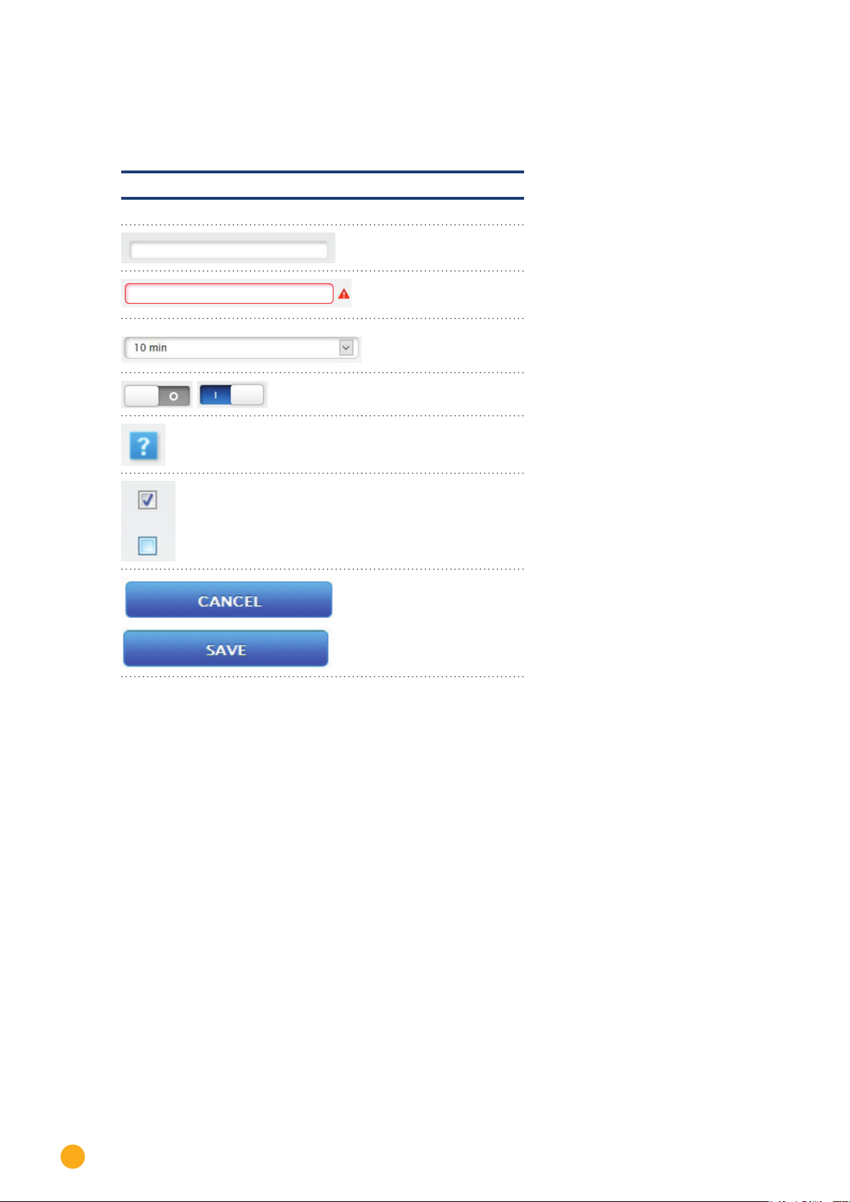
11.1.1 Control elements
The following control elements are used:
Control elements
Control element Meaning
Texteld
Texteldwithincorrector
missing entry.
Drop-down selection list
Switch
deactivated and activated
Fig.: Control elements
The question mark boxes
display additional informa
tion
Check boxes
Several boxes can be selected at one time
Command buttons for various functions
-
26

11.2 Explanations of the names in the main menu.
11.2.1 Header bar
The header contains three main sections:
Login symbol ( ):
•
Clicking on the login symbol, for example, allows you to access the info center or assistant.
Configuration:
•
Here you can change the device settings as required.
Diagnostics:
•
Diagnostics allows you to view a summary of the device information and to create a diagnostic report.
Yield data:
•
Yield data allows you to view the current plant yields and the system information.
Note
All of the points are described below in the chapters:
Login Section Menu
•
Configuration Menu
•
Diagnostics Menu
•
Yield Data Menu
•
.
Go to the Main Menu.
11.2.2 Left-side navigation menu
Depending on the tab selected, you can access additional functions from the navigation menu (left-side).
Tabs
Additional configuration sections appear according to the function selected.
11.2.3 Configuration Page
Here you have the option to make any necessary modifications to the configuration, to create back or to
reset the device.
27
Go to the Main Menu.
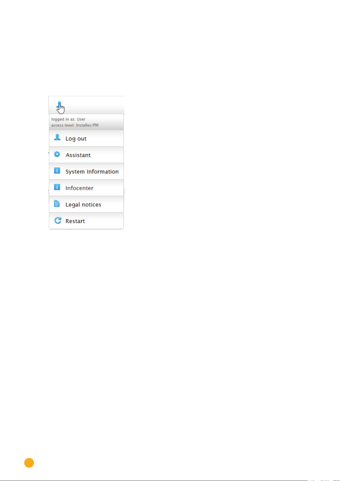
11.2.4 Login Section Menu
You can entered a password protected section by clicking on the log in button (to the right of the con-
firmation in the web interface) and entering your user and password. There is a gray line below the login
button that indicates if you are logged in and with which user level. (Refer to the
for more information)
Access Control section
Fig.: Log in button with selection box
Additional points below the login symbol:
Assistant
•
System Information
•
Info Center
•
Legal notices
•
Restart
•
Assistant
The configuration assistant can be started directly from here.
System Information
The following information can be viewed from system information:
About the Solar-Log™:
Model
•
Serial number
•
Firmware version
•
Plant data:
Plant size
•
Detected devices (depending on what devices are connected):
Battery
•
Hybrid System
•
Sensor
•
Inverter
•
Meter
•
28

Data transfers:
Last transfer with the time and date and state message (in the example: OK)
•
Go to the Main Menu.
Fig.: System Info with example plant
Info Center
Information on the following sections can be accessed here:
Solar-Log™:
•
The information about the Solar-Log™ such as the serial number, Easy Code and MAC address is locat-
ed here.
Solar-Log WEB-Enerest™:
•
Here the domain, transfer type, last transfer and ordered package can be viewed.
Documentation:
•
This item allows you to call up the corresponding manuals and download them if required or call up
the component database.
Firmware & Support:
•
In this section you can, for example, access the website, the support contact form or the FAQs.
Solar-Log™ Shop:
•
For example, you can use this item to select: the Solar-Log™ Shop, the Accessories section and the
Licenses section.
Legal notices
The legal notices indications that this product uses open source components. In addition, a list of these
components is displayed with the respective license texts.
Restart
This function resets the device.
29

Go to the Main Menu.
11.2.5 Hide arrow
The "Hide Arrow" (on the right of the header bar) allows you to increase the amount of the page displayed
in the browser by hiding the Welcome header.
Fig.: Header bar with the "Hide Arrow"
11.2.6 New Firmware
A notification is sent via the Web browser when a new firmware is version available; a green triangle with
an exclamation mark is displayed at the top in the status line. (See illustration: Signal for new firmware)
Fig.: Signal for new rmware
Note
The Automatic Firmware Update Check has to be activated in the Configuration |
System | Firmware
Update Check with notification text displayed)
menu to use this function. (See illustration: Automatic Firmware
30

Go to the Main Menu.
Fig.: Automatic Firmware Update Check with notication text displayed
The following notification text is displayed by clicking on the question mark:
"This settings allows firmware versions with critical errors to be automatically updated. However, generally,
this setting only indicates that a new firmware version is available (green exclamation mark at the top).
When clicking on the green exclamation mark in the header bar, a window with the new firmware version
will appear.
Selecting "OK" redirects you to the page of the Solar-Log™ for firmware updates. Selecting "Cancel" closes
the window.
31

Go to the Main Menu.
11.3 Setting up of the Solar-Log™ with the configuration assistant
After the initial set up of the Solar-Log™, the Solar-Log™ starts to ask about the following settings:
Language
•
Country and time
•
Display access control
•
At the end, a pop-up window appears where you can start the Solar-Log™ configuration wizard. (See the
following image: "Startup screen of the Solar-Log™ configuration wizard").
At this point, if you do not want to continue with the setup, the configuration wizard can be stopped by
clicking on the "
setup can be done manually from this menu. The Solar-Log™ configuration wizard can also be started at
any time from the
Note
Cancel" button. After clicking on "Cancel," the local "Cockpit" WEB page is started. The
Configuration | System | Configuration Wizard menu.
The configuration assistant can be stopped at any time by clicking on the "Cancel" but-
ton (left below the progress bar). The previously entered settings remain active.
Fig.: Startup screen of the Solar-Log™ conguration wizard
32

Click on the "Start" button to run the configuration wizard. Once started, the Ethernet Settings
menu appears (see image "Solar-Log™ Ethernet Settings). In the network settings can be en-
tered in the IP address, subnet mask and gateway boxes. The function "Obtain IP address auto-
matically (DHCP)" can also be deactivated if the Solar-Log™ is to be assigned a fixed IP address.
Go to the Main Menu.
Fig.: Solar-Log™ Ethernet settings from the Solar-Log™ Conguration Wizard
Click on the "Connection Test" button in the Internet connection section to check if the settings are cor-
rect.
Fig.: Example of a successful connection test
Fig.: Example of an unsuccessful connection test
33

Go to the Main Menu.
Note
If the test is successful, click on the "Next" button to go to the next section. A dialog window appears.
From this window, you can check if a new Solar-Log™ firmware version is available (see image "Displayed
Firmware Update Window").
Fig.: Displayed Firmware Update Window
By clicking on "Yes," the configuration wizard checks for a new firmware version and can install it after
that. At the end, the interface detection is performed. Otherwise, the interface detection menu appears by
clicking on "No" for the firmware update check.
All entries are saved automatically by clicking on the "Next" button. Clicking on the
"Back" button allows to go back and change the settings at any time.
Note
The device detection is to be performed after the components have been connected.
Otherwise the corresponding boxes for the components are grayed out.
34

Interface assignment
The connected components have to be assigned in the interface assignment
section.
Procedure:
Click on the plus symbol.
•
Select the device class, manufacturer, type (depending on device) and interface.
•
Confirm by clicking on "OK."
•
Repeat these steps for assigning the second interface.
•
Go to the Main Menu.
When the selection of connected devices is complete, click on the "
(See "Device Definition" chapter)
Fig.: Conguration wizard - Example - Interface Assignments
Start" to start the Device Detection.
Note
The device detection can be canceled by clicking on the "Skip" button – for example,
when there is incorrect interface assignment or number of detected devices.
35

Go to the Main Menu.
Click on "OK" after a successful detection. Then click on "Next." The device configuration menu appears.
In the device configuration, one can, for example, define the generator output, the module fields and the
names of the individual components. (Also refer to the chapter "
Device Configuration")
Fig.: Example – Conguration Wizard – Device Conguration
The "portal" page is loaded by clicking on "next." Here the data transfer to the Solar-Log WEB Enerest™
portal can be activated.
The box "Portal Server" appears once the data transfer to the Solar-Log WEB Enerest™ portal is activated.
There are two options for entering the portal server:
Option when the Solar-Log™ has already been registered on the portal:
•
If you know the portal server, you can manually enter it. Otherwise, there is the option to automatically
enter the portal server by using the "Obtain automatically" function (above the globe symbol).
Option when the Solar-Log™ has not been registered on the portal:
•
If the Solar-Log™ has not been registered on the portal, the function to obtain portal server automat-
ically can be started with the globe symbol. The "portal server" box is grayed out and the Solar-Log™
goes into a waiting state and remains in this state until it has been registered in the Enerest portal (see
the Solar-Log WEB Enerest™ User Manual, available to download from https://www.solar-log.com/en/
support/downloads/manuals). After that the Solar-Log™ obtains the portal server automatically.
After clicking on "Next," the configuration wizard is finished and a summary is displayed. (See illustration:
"Configuration Wizard Summary")
36

Fig.: Example – Conguration Wizard Summary
Go to the Main Menu.
11.3.1 Solar-Log 50 Manual Configuration
After the device connection has been established and the Solar-Log™ has been connected to the Internet
router, the basic configuration of the Solar-Log 50 is done via a web browser.
All settings made at the initial startup can be changed later at any time.
Procedure:
Enter http://solar-log-wxyz in the web browser address bar (wxyz stands for the last 4 digits from
•
serial number of the Solar-Log™).
A selection of display languages is displayed.
•
Select the desired Display Language. Click on Continue.
•
Define the country and time zone. Continue.
•
The Access Protection menu is displayed. Click on Continue after defining the user password.
•
The Configuration Wizard is displayed. Click on Cancel to perform a manual configuration.
•
Select "Configuration" from the menu in the header bar.
•
The following can be manually configured from the Configuration menu:
•
• Network
• Internet
• Devices
• Data
• System
(For a detailed description of the configuration, refer to the chapter: "
Configuration Menu")
37

Main menu
12 Main menu
The main menu on the Solar-Log™ is divided into three sections:
Configuration
•
Diagnostics
•
Yield data
•
In addition, the following sub-menus are displayed in this view:
Cockpit
•
Table
•
These are also located on the left side of the of the Virtual LCD Display and in additional sub-menus (de-
pending on connected the devices) and as a selection in the main navigation menu.
12.1 Virtual LCD Display
The Virtual LCD Display is located above the left navigation menu and displays the notifications from the
Solar-Log™ in the form of codes and symbols in addition to the date and time. The codes and symbols are
described in more detail below (see chapter: "Notifications on the Virtual LCD Display"). The notications
are in real time.
Fig.: Virtual LCD Display
38

13 Configuration Menu
The Configuration menu is divided into the following sub-sections:
Network
•
Internet
•
Devices
•
Feed-in management
•
Data
•
System
•
The following sub-sections of the menu will be explained separately in the following chapters.
13.1 Configuring network settings
Configuration Menu
Open the dialog box.
Select Configuration | Network from the menu.
The Network menu is divided into the following sub-sections:
Ethernet
•
Proxy
•
Note
The network should always be available (24/7) to ensure comprehensive logging and
reliable monitoring.
Note
The Solar-Log 50 is equipped with a 7-day memory to prevent data transfer failures (e.g.
router failure).
39

Configuration Menu
13.1.1 Ethernet
Fig.: Ethernet settings
The Ethernet settings for the Solar-Log™ are adjusted in this tab.
Obtain IP address automatically (DHCP)
Here the following options are available:
Activate Obtain IP address automatically
•
Deactivate Obtain IP address automatically.
•
.
With the default settings of the Solar-Log™, the "
tive. DHCP also have to be enabled on the Internet router for the the Solar-Log™ to obtain an IP address.
If the Solar-Log™ receives a
needs to be
IP address
The IP addresses need to be in the same network to successfully establish a connection to the device. That
means the first three blocks of the IP address are identical; only the last block differs.
An example:
192.168.100.1 for the router
192.168.100.2 for the Solar-Log™ etc.
Subnet mask
The Subnet mask is 255.255.255.0 by default and must be the same for every device in the subnet.
deactivated. The following fields need to be adjusted according the network's configurations.
fixed IP address later, the Obtain IP address automatically (DHCP) switch
Obtain IP address automatically (DHCP)" option is ac-
40
Gateway
The gateway is typically the IP address of the router to which Solar-Log™ is connected. That IP address is
to be entered here.

Configuration Menu
Alternate DNS server
In some networks, the DNS server is a separate address for resolving Internet addresses (unlike a gate-
way). If an Alternate DNS server is needed, switch the function to activated and enter the IP address of the
DNS server.
Once finished, click on
Save.
Connection Test
Use the "Connection Test" button to determine if the entries are correct and if a connection can be suc-
cessfully established. The message indicates if the connection was successful or not. (See the following
illustrations)
Fig.: Example of a successful connection test
Fig.: Example of an unsuccessful connection test
41

Configuration Menu
13.1.2 Proxy
Fig.: Example of proxy settings
The proxy function is not enabled by default. Configure the proxy in the Configuration | Network | Proxy
menu.
The proxy settings need to be configured in the Solar-Log™ to enable Internet communication via the
proxy server. Proxy servers are typically used in the networks of organizations and companies.
Procedure
When using a proxy, select Connect Method.
•
Enter proxy server, port, user name and password.
•
SAVE the settings.
•
42

13.2 Internet Configuration
Select Configuration | Internet from the menu.
The following tabs can be displayed:
Portal
•
13.2.1 Portal
The following functions are available in this tab:
Activate/deactivate transfers
•
Activated:
•
• Status
• Test
Configuration Menu
Fig.: Example of portal settings
Note
Please download the Solar-Log WEB Enerest™ Home User Manual from our website to
efficiently use and configure the Solar-Log WEB Enerest™ Home. Located here:
https://www.solar-log.com/en/support/downloads/
43
Configuration Menu
Solar-Log WEB Enerest™ section
The following selection options are available in this section:
Activate/deactivate transfers
•
Portal server. There are two options for entering the portal server:
•
• Option when the Solar-Log™ has already been registered on the portal:
If you know the portal server, you can manually enter it. Otherwise, there is the option to automati-
cally enter the portal server by using the "Obtain automatically" function (above the globe symbol).
• Option when the Solar-Log™ has not been registered on the portal:
If the Solar-Log™ has not been registered on the portal, the function to obtain portal server auto-
matically can be started with the globe symbol. The "portal server" box is grayed out and the So-
lar-Log™ goes into a waiting state and remains in this state until it has been registered in the Enerest
portal (see the Solar-Log WEB Enerest™ User Manual, available to download from https://www.
solar-log.com/en/support/downloads/manuals). After that the Solar-Log™ obtains the portal server
automatically.
Transfer interval
•
SAVE the settings.
•
Status section
The following fields are displayed in the Status section:
Date (Last Export)
•
Error (Last Export)
•
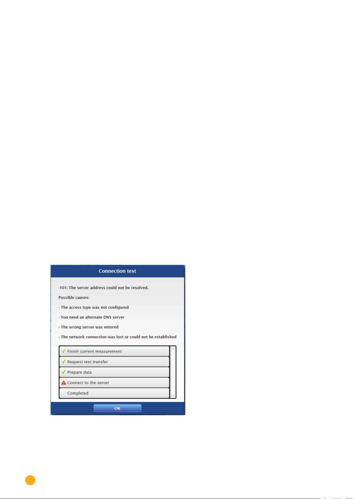
Test section
A connection test can be performed in the Test section. A separate pop-up window is displayed with the
progress of test. The connection test also indicates if the test was successful or not. If it was not successful,
it displays the error. After the tests are finished, possible causes for the connection problems are listed.
(See the following example illustration).
44
Fig.: Example - Transfer Test with an Error Image

Configuration Menu
After confirming with OK, an additional field with the status of the test is displayed in the Test section.
Question marks indicate that the test was unsuccessful and possible causes are listed.
Fig.: Example - Connection Test with an Error
13.3 Configuring connected devices
From the menu Configuration | Devices, the PV plant components connected to the Solar-Log™ can be
defined
•
detected
•
and configured.
•
We recommend the following procedures for new installations:
Define the interface to be used for the connected devices.
•
Device detection.
•
Device configuration.
•
45

Configuration Menu
13.3.1 Device definition
To define the device definition, go to the Configuration | Devices | Definition menu. The interfaces are
assigned in this section.
Configuring the device interface section
The interface for the connected devices needs to be defined from the Configuration | Devices | Definition
| Interfaces
Procedure:
Go to the plus symbol under "Interface assignments".
•
menu before performing a device detection.
Fig.: Interface denition via the plus symbol
In the following window, the connected components can be selected in the box Device Class.
The following device classes can be defined:
Battery
•
Hybrid System
•
Sensor
•
Inverter
•
Meter
•
Depending on the device class and/or the selected
Type, Interface and Baud rate.
Note
Caution: Using different manufacturers on the same serial bus may cause communication
problems.
Only the network interface (Ethernet) can have multiple assignments according to our
component database at https://www.solar-log.com/en/support.
Manufacturer, additional boxes visible:
46
If the device class is correct, confirm the selection with
described.
If all of the connected components have been selected and confirmed with
OK. Define additional connected device classes as
OK, an overview is displayed in

the interface assignments. (See illustration: "Overview of the selected components")
Configuration Menu
Fig.: Overview of the selected components
From the overview, there is the option to check whether the settings are correct and, if need be, adjust or
delete them with the
components.) Additionally, the following is displayed in the overview of the device interfaces:
Device class
•
The selected devices can be seen here. In the example:
• Sensor
• Inverters
Manufacturer
•
The manufacturer is displayed in this column. In the example:
• Mencke&Tegtmeyer
• Diehl AKO
Type
•
The defined types are listed in this column. In the example:
• Sensor Full/Light
• EIA485
Interface
•
Interface indicates which interface and baud rate the devices are using.
When all of the definitions are correct, then click on
and symbols. (The symbols are only displayed by moving the mouse over the
SAVE.
47

Configuration Menu
13.3.2 Device Detection
During the Device Detection process, all of the predefined components in the Device Definition menu
which are connected to the Solar-Log™ interfaces are searched for and recognized. During the Device De-
tection process, the Solar-Log™'s internal data structure is prepared for these devices.
Procedure:
Select Configuration | Devices | Detection from the menu.
•
The devices which were predefined in the Device Definition menu are displayed in the overview.
•
START Device Detection.
•
The Device Detection goes from the top listed interface to the bottom listed interface when searching
•
for devices.
The progress of the device detection is displayed in a window that automatically appears.
The detected devices are displayed with the number of devices per bus.
•
If all of the devices on a bus have been detected, the rest of the search can be skipped. The search is
•
then continued on the next bus.
The Device Detection is completed once all of the buses have been checked.
•
Status message: New device detected, the data is being reformatted.
48

Configuration Menu
13.3.3 Configuring devices
After the Device Detection has been successfully completed, the detected devices have to be configured
in the
Configuration | Devices | Configuration menu.
Depending on the device, different settings might be needed for the configuration.
Procedure:
Select the device that needs to be configured in the Device Configuration section.
•
Depending on the device type, different configuration boxes appear.
•
The sections below—Module Fields, Power Output and Descriptions—are largely identical
•
Enter the module field, connected generator power and description.
13.3.4 Configuring inverters
The following values have to be configured for inverters:
Maximum AC Power
•
Pac Correction Factor
•
Module field
•
Generator Power and MPP tracker output (according to the string plan)
•
Labels or names of the inverters and/or MPP trackers.
•
Procedure:
Select Device.
•
Enter
•
the maximum AC power from the inverter's data specification in the section: Module Field, Power
•
and Name.
Enter the Pac Correction Factor (for more information, refer to the section "Generation Information
•
on PAC Correction Factor
Define the module field.
•
Inverters can be assigned to be different module fields. See Chapter:„Modulfelder“.
Generator Power
•
The connected power of the individual inverters in Wp. The total power can be calculated using the
formula: Module power * Number of modules. The output does not have to be entered. It is calculated
from the total generator power values that have been entered for the
The generator power for every tracker needs to be entered if the inverter has several MPP track-
•
ers.
IA distinct name can be assigned to every generator/MPP tracker in the Label box.
•
SAVE the settings.
•
")
Mpp Tracker.
49

Configuration Menu
13.3.5 Generation Information on PAC Correction Factor
At photovoltaic plants, several measuring points and power generators (inverters) are combined with one
another. The Solar-Log™ evaluates this data and partially looks for any correlations.
For example, if the total amount of energy produced based on what the inverters display is compared with
the values from calibrated power meters, deviations of up to 8% can arise.
In practice, meters and inverters both can display too much or too little kWh.
To correct these inaccuracies in the medium term, the Solar-Log™ firmware uses a PAC correction factor.
Calculating the PAC correction factor
All yield data are always stored internally without any correction factor. This factor is applied only when
the data are displayed. The factor can therefore be adjusted at any time.
The formula for calculating the correction factor is as follows:
(Yield power meter / yield inverter) * 1000
If the inverter does not have a display, it is advisable to use the values which are recorded by the So-
lar-Log™ from a period over a week.
That is why it is recommended to leave the default PAC correction factor at 1000 initially.
The correction factor can be adjusted yearly after receiving the statement from the utility company.
Example calculation:
Inverter 1 Inverter 2 Calibrated power meter
Total energy Total energy Total energy
259.12 kWh 305.22 kWh 550.55 kWh
Total = 564.34 kWh Deviation= 13.79 kWh
By comparing the values, you see that the inverters are more likely to display too much output.
Pac Correction Factor
Calibrated power meter total energy Inverter total energy
550.5 kWh 564.34 kWh
50
Calculated PAC correction factor in the example:
(550.55 kWh/564.34 kWh)* 1000= 975.66
Rounded PAC correction factor = 976

Configuration Menu
13.3.6 Configuring power meters
An operating mode needs to be assigned to power meters to configure them.
Possible operating modes for power meters:
Generator (records the individual producers, e.g. PV inverter)
•
Meter for the entire plant (records the complete PV plant output)
•
Consumption meter (records the complete consumption)
•
Sub-consumption meter (records the consumption from individual appliances)
•
Battery (Bi-directional meter)
•
Battery (Bi-directional meter)
•
Deactivated
•
Depending on the selected operating mode and/or meter type, additional selection boxes appear, such as
Energy type and/or Impulse rate.
Note
Several consumption meters can be defined for every plant. Their measurements are
added to the total consumption.
Note
A sub-consumption meter is a consumption meter whose consumption has already
been recorded by another meter. It is used to visualize the consumption from a particular appliance or group.
Procedure
Select Device
•
Select the desired operating mode from the Meter configuration section.
•
If needed, assign a plant group to this meter.
•
SAVE the settings.
•
51

Configuration Menu
13.3.7 Configure the battery
The following configurations can be made here for the connected battery.
Battery size
•
Enter the battery size in Wh in this box.
Consumption meter includes battery charge
•
This box enables recording the battery charges from the consumption meter.
Note
The following components always have to be used for battery monitoring to work:
=> Inverters
=> Battery
=> Consumption meter
13.3.8 Module Fields, Power Output and Descriptions
Depending on the device type (power meter, inverter, etc.), different settings can adjusted from the Mod-
ule Fields, Power Output and Descriptions
Configuring inverters
•
Configuring power meters
•
In this section, for example, the device name can be changed and the nominal power (maximum AC out-
put) of the individual devices can be defined.
menu. See the following chapters:
Module Fields
Each connected MPP tracker is assigned to a module field. Module fields are subdivided according to the
type of the solar module, angles of inclination and alignment. If all modules within a system are of the same
type and have the same alignment, only one module field, e.g. "1", is defined. MPP trackers that are not
used must be switched off (switched to "0").
Additional module fields need to be defined for modules with different alignments and module types. Ide-
ally, each field should be made up of at least two individual MPP trackers, which monitor each other. The
module fields are used for performance monitoring.
Example module fields:
A plant with 23.6 kWp is divided into:
3 x SMA SB5000TL and
2 x SMA SB2500.
18 kWp is located on a barn roof with 30° inclination, 20° South-East deviation, and 5 kWp on an adjoining
garage roof, 32° inclination, 0° South deviation.
52

This results in two module fields according to the following table:
Division of the module fields
Configuration Menu
Location Inverter MPP Tracker
Module field
output
Barn 1. SB5000TL 2000 1
Barn 1. SB5000TL 2000 1
Barn 1. SB5000TL 2200 1
Barn 2. SB5000TL 2000 1
Barn 2. SB5000TL 2000 1
Barn 2. SB5000TL 2200 1
Barn 3. SB5000TL 2000 1
Barn 3. SB5000TL 2000 1
Barn 3. SB5000TL 2200 1
Garage 1. SB2500 2500 2
Garage 2. SB2500 2500 2
Changing the device order section
The sequential order of the inverters and other devices is determined during inverter detection. They are
normally sorted by their serial number or communications address.
The order can be changed through drag and drop from the
menu.
Order
Configuration | Devices | Configuration |
53

Configuration Menu
13.4 Feed-in management
13.4.1 Plant parameters
The plant data is entered in the plant parameters tab.
Maximum apparent power from the generating plant
•
Enter the maximum plant power output in volt-ampere (VA) here. This value has to match the value
registered with the grid company.
Typically, this calculation is based the total module power output.
13.4.2 Active power
The following modes are available from the Feed-in Management | Active power menu:
Deactivated
•
70% fixed reduction
•
70% Fixed reduction with the calculation of self-consumption
•
Adjustable reduction
•
Adjustable reduction with the calculation of self-consumption
•
Fixed reduction in watts
•
Fixed reduction in watts with the calculation of self-consumption
•
Percentage of consumption for an adjustable reduction
•
Note
The active power reduction mode that needs to be implemented for a particular PV plant
is determined by the current national laws, standards and grid operator's requirements.
The planner and/or installer of your plant or the respective grid operator can provide
you with information regarding the mode of active power reduction that needs to be
used.
Note
The feed-in management functions are not supported by all makes and models of invert-
ers.
Prior to installation please check whether power management and reactive power con-
trol are supported by the inverters used.
Please consult our inverter database for an overview of all the inverters supported by
Solar-Log™ devices and more details on supported functions of a particular inverter:
https://www.solar-log.com/en/support.
Interface assignments section
The inverters with their assigned interfaces that are connected to the Solar-Log™ are displayed in this
section.
Select the inverter(s) to control and activate it/them.
54

Configuration Menu
Dynamic control for different module orientations section
Depending on the plant, there might be different module orientations. To integrate these differences with
the active power, the switch "Dynamic control for different module orientations" needs to be activated
(deactivated by default). This switch is located in the
vate this.
When this option is activated, different reduction commands are sent to the inverters, e.g. taking their ori-
entation into consideration, to maximize the amount of power fed into the grid without exceeding the limit.
The advantage here, for example, is that when some inverters are performing below a 70% limit, the output
from other inverters can be adjusted above the 70% to balance the final output to 70%.
Feed-In Management | Active Power menu. Acti-
13.4.3 Active power deactivated
When this menu item is selected, active power is deactivated. However, the controllable interfaces can still
be selected.
13.4.4 70% fixed reduction
By activating this menu item the inverter(s) are controlled to be fixed at 70% of the installed DC power.
Enter the
tion | Devices | Configuration
The maximum power output for the inverters can be calculated from the connected generator power value
that has been entered.
Procedure
•
•
•
Maximum AC Power and Connected Generator Power as reference values in the Configura-
menu.
Select 70% fixed reduction.
Select the inverter(s) to control in the Interface assignments section.
SAVE the settings.
Note
Changes to the Maximum AC Power of the inverter in Configuration | Devices | Con-
figuration
Enter your password via the Log-on as Installer / PM to enable changes.
Note
The 70% reduction is always applied to the entire plant.
All of the inverters are controlled on the same level by the Solar-Log™, independent of
their alignments (east-west orientation). This can lead to a lower feed-in amount than
the maximum allowed.
menu are disabled.
Example 1
DC power 12 kWp
AC power 12 kW
70% of the DC power corresponds to 8.4kW.
As the AC and DC power are identical, the down-control is correct.
55

Configuration Menu
Example 2
DC power 12 kWp
AC power 10kW
70% of the DC power corresponds to 8.4kW.
For this reason the inverter controlled by the Solar-Log™ is reduced to 84% (8.4kW) and not only to 70%
(7kW).
13.4.5 70% Fixed reduction with the calculation of self-consumption
This function is an enhancement to the 70% fixed reduction described in the previous chapter.
The Solar-Log™ needs to be linked to a consumption meter to implement this function. Please note the
instructions in chapter”
The configuration of this corresponds to that already described for the 70% fixed reduction.
Procedure
Select 70% Fixed reduction with the calculation of self-consumption
•
Select the inverter(s) to control in the Interface assignments section.
•
SAVE the settings.
•
External power meter”.
Note
The Solar-Log™ needs to be linked to a consumption meter to implement this function.
Please note the instructions in chapter”
The current amount of self-consumption is calculated by employing a power meter for self-consumption.
The consumption is calculated with the energy generated by the inverter.
If the difference between the current production and consumption is lower than 70% of the module‘s pow-
er output, the inverters are regulated accordingly, so that the amount of power at the feeding point is still
only at 70% of the connected generator power.
External power meter”.
13.4.6 Adjustable reduction
This function allows the maximum amount of grid feed-in power to be configured. The reduction level in
regard to the amount of connected generator power can be freely defined as a percentage (X%). The So-
lar-Log™ only regulates the inverters when the amount of feed-in power for the grid has reached the limit.
Procedure:
Select Adjustable reduction.
•
Enter the percentage for the adjustable reduction.
•
Select the inverter(s) to control in the Interface assignments section.
•
SAVE the settings.
•
56

Configuration Menu
13.4.7 Adjustable Reduction with the Calculation of Self-Consumption
This function allows the maximum amount of grid feed-in power to be configured. The reduction level
in regard to the amount of connected generator power can be freely defined as a percentage (X%). The
amount of self-consumption is taken into account for this calculation. The Solar-Log™ only regulates the
inverters when the amount of feed-in power for the grid has reached the limit. If there is enough self-con-
sumption, the inverters continue to operate without any reductions.
Procedure:
Select Adjustable reduction with the calculation of self-consumption
•
Enter the percentage for the adjustable reduction.
•
Select the inverter(s) to control in the Interface assignments section.
•
SAVE the settings.
•
Note
The Solar-Log™ needs to be linked to a consumption meter to implement this function.
Please note the instructions in chapter”
External power meter”.
13.4.8 Fixed reduction in watts
This function allows the maximum amount of grid feed-in power to be configured. The reduction level in
regard to the amount of connected generator power can be freely defined to a particular output level (W).
The Solar-Log™ only regulates the inverters when the amount of feed-in power for the grid has reached the
limit.
Procedure:
Select Adjustable reduction.
•
Enter the Output (W) for the adjustable reduction.
•
Select the inverter(s) to control in the Interface assignments section.
•
SAVE the settings.
•
13.4.9 Fixed reduction in watts with the calculation of self-consumption
This function allows the maximum amount of grid feed-in power to be configured. The reduction level in
regard to the amount of connected generator power can be freely defined to a particular output level (W).
The amount of self-consumption is taken into account for this calculation. The Solar-Log™ only regulates
the inverters when the amount of feed-in power for the grid has reached the limit. If there is enough
self-consumption, the inverters continue to operate without any reductions.
Procedure:
Select Adjustable reduction with the calculation of self-consumption
•
Enter the Output (W) for the adjustable reduction.
•
Select the inverter(s) to control in the Interface assignments section.
•
SAVE the settings.
•
57

Configuration Menu
Note
13.4.10 Percentage of consumption for an adjustable reduction
This function allows the maximum amount of power generated by the inverter to be configured. The per-
centage configured (freely adjustable) results in a corresponding reduction in regard to the total consump-
tion at the inverter.
Example:
The total consumption of an installation is at 2000 W and the reduction of the inverters is configured to
90%, leaving 1800 W. 200 W has to be purchased from the grid to cover the total consumption.
Procedure:
Select the percentage of consumption for the adjustable reduction.
•
Enter the percentage (%) for the adjustable reduction.
•
Select the inverter(s) to control in the Interface assignments section.
•
SAVE the settings.
•
The Solar-Log™ needs to be linked to a consumption meter to implement this function.
Please note the instructions in chapter”
External power meter”.
13.5 Editing Data
The Configuration | Data menu offers several functions in regard to the data recorded by the Solar-Log™
and contains the following options:
System backup
•
Backup
•
Reset
•
13.5.1 System backup
The Configuration | Data | Backup menu offers the following functions:
Restore configuration from hard disk
•
Save configuration to hard disk
•
Save configuration to USB
•
Restore configuration from USB
•
The system data consist of all the data that have been saved in the configuration. It is recommended al-
ways to make a backup of the system data before changing the configuration or updating the firmware.
58

Restoring configuration from hard disk section
This function imports the configuration file from the solarlog_config.dat file into the Solar-Log™.
Procedure
Click on Browse.
•
The file manager of your OS appears.
•
Select the DAT file that is to be imported.
•
The selected firmware's file name is displayed.
•
Click on Upload.
•
The configuration is being imported. Please wait a moment.
•
The Solar-Log™ reboots itself.
•
Saving configuration to hard disk section
With the function a configuration file can be created and saved to a hard drive.
A Solar-Log configuration file has the following file name:
"solarlog_config.dat."
Procedure
Click on Prepare.
•
After the data has been prepared, the Download option is displayed.
•
Click on Download.
•
Depending on your browser settings, a window pops up with the options to open the file with a pro-
•
gram or save file.
Select Save file.
•
The file is saved in the download folder.
•
Configuration Menu
59

Configuration Menu
Alternative procedure
Click on Prepare.
•
After the data has been prepared, the Download option is displayed.
•
Right click with the mouse on Download.
•
Select Save link as.
•
The file manager of your OS appears.
•
Select the desired location to save the file to.
•
Select save.
•
The file is saved in the selected folder.
•
Saving configuration to USB section
With this function, a backup can be saved to a USB stick which is directly connected to the device.
Procedure
Touch Save.
•
The configuration is being created. Please wait a moment.
•
The progress and status of the update are displayed.
•
Finish current measurement.
Search for USB stick
Save configuration.
The solarlog_config_YYMMDD.dat file is saved in the /Backup directory of the USB stick.
•
YYMMDD stands for year, month and day - each two digits, e.g. solarlog_config_180828.dat is then the
backup from 28 August 2018.
The configuration file can be saved elsewhere as a backup or imported into the Solar-Log™ again.
•
Restoring configuration from USB section
This function imports the solarlog_config.dat (or solarlog_config_YYMMDD.dat) configuration file from a
USB stick which is directly connected to the device into the Solar-Log™.
Procedure
Click on RESTORE.
•
Backup files are searched for on the USB stick that is directly connected to the Solar-Log™
•
First it looks in the main directory of the USB stick for solarlog_config.dat, then it looks in the /backup
directory. And lastly it looks in the backup directory for solarlog_config_YYMMDD.dat. When it looks
for the solarlog_config_YYMMDD.dat. file, it loads the latest file.
Start this search.
•
When a configuration file is found on the USB stick, click on RESTORE to import it.
•
This data is being imported.
Please wait.
The Solar-Log™ reboots itself.
•
The configuration file was imported.
•
60

13.5.2 Backup
The Configuration | Data | Backup menu offers the following functions:
Restore data backup from hard drive.
•
Save data backup to hard drive.
•
Save data backup to a USB stick.
•
Restore data backup from a USB stick.
•
Restore data backup from hard drive section
This function restores the backup file with the name solarlog_backup.dat to the Solar-Log™.
Procedure
Click on Upload.
•
The file manager of your OS appears.
•
Select the DAT file that is to be imported.
•
The selected backup's file name is displayed.
•
Click on Upload.
•
The configuration is being imported. Please wait a moment.
•
The Solar-Log™ reboots itself.
•
Configuration Menu
Saving data backup to hard drive section
With the function a backup can be created and saved to a hard disk.
A Solar-Log backup file has the following file name:
solarlog_backup.dat.
Procedure
Click on Prepare.
•
The progress and status of the update are displayed.
•
Finish current measurement.
Search for USB stick
Save the configuration after the data has been prepared, the Download option is then displayed.
Click on Download.
•
Depending on your browser settings, a window pops up with the options to open the file with a pro-
•
gram or save file.
Select Save file.
•
The file is saved in the download folder.
•
Alternative procedure
Click on Prepare.
•
The progress and status of the update are displayed.
•
Finish current measurement.
Search for USB stick
Save configuration.
After the data has been prepared, the Download option is displayed.
•
Right click with the mouse on Download.
•
Select Save link as.
•
The file manager of your OS appears.
•
Select the desired location to save the file to.
•
Select save.
•
The file is saved in the selected folder.
•
61

Configuration Menu
Saving data backup to USB section
With this function, a backup can be saved /Backup directory of a USB stick which is directly connected to
the device.
Procedure
Touch Save.
•
The backup is being created. Please wait a moment.
•
The progress and status of the update are displayed.
•
Finish current measurement.
Search for USB stick
Save configuration.
The solarlog_backup_YYMMDD.dat file is saved in the /Backup directory of the USB stick.
•
YYMMDD stands for year, month and day - each two digits, e.g. solarlog_backup_180828.dat is then
the backup from 28 August 2018.
The Solar-Log™ backup can be copied to another storage medium or imported into the Solar-Log™ again.
Restoring backup from USB section
This function restores a backup file with the name solarlog_backup.dat from the
USB stick connected directly to the device to the Solar-Log™.
Procedure
Click on RESTORE.
•
Backup files are searched for on the USB stick that is directly connected to the Solar-Log™
•
First it looks in the main directory of the USB stick for solarlog_backup.dat, then it looks for the same
file name in the /backup directory. And lastly it looks in the backup directory for the file solarlog_
backup_YYMMDD.dat. When it looks for the solarlog_config_YYMMDD.dat. file, it loads the latest file.
Start this search.
•
When a configuration file is found on the USB stick, click on Restore to import it.
•
The backup is being restored. Please wait a moment.
•
The Solar-Log™ reboots itself.
•
The configuration file was imported.
•
62

Configuration Menu
13.5.3 Reset
The Configuration | Data | Reset menu offers the following functions:
Reset the yield data.
•
Reset the inverter configuration.
•
Restore factory settings.
•
Resetting yield data section
In certain circumstances after an inverter detection, it may occur that incorrect or unusable data is dis-
played. In this case, the stored data can be deleted without having to reconfigure the Solar-Log™ com-
pletely.
Procedure
Click on RESET.
•
If you are sure that the data should be deleted, click on Continue. Otherwise click on Cancel.
•
The data is being deleted.
•
The Solar-Log™ reboots itself.
•
Resetting inverter configuration section
If the Device Detection needs to be started again, it is recommended to delete the previous inverter con-
figuration with this function.
Procedure
Click on RESET.
•
If you are sure that the inverter configuration should be deleted, click on Continue. Otherwise click on
•
Cancel.
The data and inverter configuration are deleted.
•
The Solar-Log™ reboots itself.
•
Restore factory settings section
This function restores the Solar-Log™ to its factory settings. All of the yield data and configuration is delet-
ed.
Procedure
Click on RESET.
•
If you are sure that the data should be deleted, click on Continue. Otherwise click on Cancel.
•
The factory settings are being restored.
•
The Solar-Log™ reboots itself.
•
Note
The network settings remain when this function is used.
63

Configuration Menu
13.6 System Configuration
The Configuration | System menu has the basic settings for the Solar-Log™ and contains the following
tabs:
Access control
•
HTTPS
•
Language/Country/Time
•
Licenses
•
Firmware
•
13.6.1 Access control
Access protection for of the Solar-Log™ can be configured in this menu. The following section can be re-
stricted with pin codes or passwords.
Access protection for the browser menu.
•
Access protection for the browser menu
In this section, the following parts of the Solar-Log™'s browser menu can be
restricted with a password:
User
•
General access to the
Installer
•
Access to the
Installer/PM
•
Access to the
The default password for access to the Feed-in Management menu is PM. Access for users and installers is
not restricted.
Procedure
Activate the password restriction for the desired menus.
•
Enter a secure password for each of the menus.
•
Enter the password again.
•
SAVE the settings.
•
Configuration menu.
Configuration | Feed-in Management menu.
Browser menu.
64

Configuration Menu
13.6.2 HTTPS
The following section are located here:
SSL certificate
•
User-specific certificate
•
SSL certificate
An SSL certificate is a code on the web server that secures online communication. When a web browser
connects to a website, the SSL certificate provides a secure connection.
The Solar-Log™ uses such an SSL certificate. This can be imported into the web browser or the operating
system. There is also the option to use your own SSL certificate instead of the Solar-Log™ certificate.
There are four different boxes under SSL certificate:
Status:
•
This indicates which certificate the Solar-Log™ is currently using.
•
SSL certificate fingerprint:
•
The correctness and authenticity of the certificate used can be verified by means of the fingerprint.
This is done by comparing the string displayed in the field with the reference sequence in the browser.
Issue a new certificate:
•
You can use the button issue a new certificate, but the certificate currently used will be irrevocably
deleted.
Download SSL certificate:
•
The Download button offers the option to download the SSL certificate and to import it into the
browser or operating system.
User-specific certificate
An user-specific certificate can be uploaded in this section. Go to "Browse" to select the certificate you
want to upload.
Note
Please note the help texts in the individual sections.
65

Configuration Menu
13.6.3 Language/Country/Time
The following options are available from the Configuration | System | Language/Country/Time menu:
System language of the Solar-Log™.
•
Country/Location of the Solar-Log™.
•
System time of the Solar-Log™.
•
Time synchronization.
•
Language section
Procedure
Select the desired Language in the selection menu.
•
The selected display language affects the display in the web browser.
SAVE the settings.
•
Country section
Procedure
Select your Country in the selection menu.
•
The country setting affects how the date, time and currency formats are displayed.
SAVE the settings.
•
Time section
The clock time is factory-set, but it may be lost due to long periods of storage.
The time zone, date and summertime values must be set correctly, so that no incorrect statuses or results
are obtained during monitoring and graph display, e.g. when e-mail messages are sent or when a curve is
displayed on the day graph.
Fig.: Conguring the time on the Solar-Log™
Adjust the time in the Configuration | System | Language/Country/Time menu.
Adjust the new system time
Procedure
The current system time is displayed.
•
Enter the following format to change the date and time:
•
DD/MM/YY HH:MM:SS
For example: 19.07.18 14:02:26 PM (14:02:26) for 19 July 2018 14 Hours 02 Minutes 26 seconds (14:02
p.m.)
SET a new date and time.
•
66

Configuration Menu
Adjust the time zone
Procedure
Enter the time difference in hours (time zone).
•
Default: GMT +1
Save the Entry .
•
Set Day Light Saving Time.
Procedure
Select the corresponding Day Light Saving Time settings:
•
Options: no, CEST (Central European Summer Time), USA, Australia.
SAVE settings.
•
Automatic time synchronization section
To automatically synchronize the system time, the Solar-Log™ regularly contacts a network time protocol
(NTP) server.
If the Solar-Log™ is connected to the Internet via a router, the synchronization occurs during the night.
Procedure
Activate the Automatic time synchronization button.
•
SAVE the settings.
•
Update now function, the time synchronization with the NTP server can be manually started. The NTP port
123 needs to be enabled in the gateway or firewall.
Note
It is important that the time on the device is synchronized or manually set the correct
time, otherwise functionality is limited (e. g. no resetting of the device) and no logging is
performed.
67

Configuration Menu
13.6.4 Licenses
Certain Solar-Log™ functions have to be activated by entering a license code. You receive a license certifi-
cate after purchasing a license for a particular function. The licenses are always linked to the serial number
of the particular Solar-log™ and can only be used with the device with this serial number.
Perform the following steps to purchase a license:
Go to the license portal at https://shop.solar-log.com.
•
Log on with your Enerest account.
•
After you have to enter the serial number of the Solar-Log™, a list of compatible licenses is displayed.
•
You can only select one license from the list. After the selection has been made, the web-shop pay-
•
ment options appear.
After the payment confirmation, the license is valid.
•
Automatic import:
Go to the Configuration | System | Licenses WEB menu of the Solar-Log™.
•
Click on Synchronize.
•
Now the Solar-Log™ connects to the license server and downloads all of the active licenses.
•
Manual import:
Download the license file from the License portal.
•
Go to the Configuration | System | Licenses WEB menu of the Solar-Log™.
•
Click on the plus symbol and select the license file.
•
After importing the license, it is activated immediately and “
The following licenses can be purchased for the Solar-Log 50 (refer also to the specifications on our web-
site https://www.solar-log.com/de/produkte-komponenten/solar-logTM-hardware):
Expansion license to 30 kWp.
•
Expansion license to 10 components.
•
Note
Licenses are linked to the device (serial number). The license has to be purchased again
if a device has been replaced after the warranty has expired.
Installed” is displayed.
68
Note
If a Solar-Log™ with a license has a defect during the warranty period, a license can be
requested for the replacement device. There are no costs involved, provided that the
defective device is returned to Solare Datensysteme GmbH.
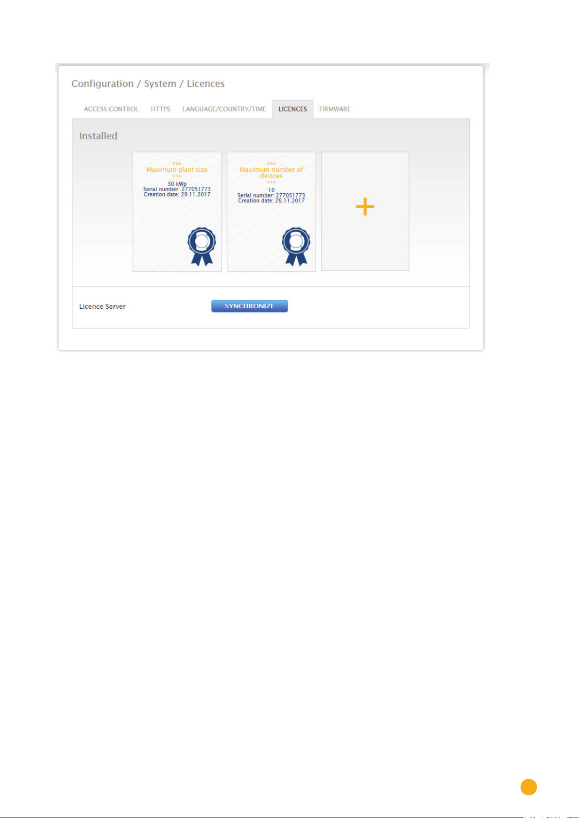
Configuration Menu
Fig.: Solar-Log™ with installed licenses
13.6.5 Firmware
The firmware tab offers the following functions:
Information about the current firmware version.
•
Firmware Update.
•
Status section
The firmware version currently installed on the Solar-Log™ is displayed. The version number contains three
sections:
Version number Build Date
4.2.0 108 28.08.2018
69

Configuration Menu
Updating firmware manually section
This function allows a new firmware to be imported from a disk.
Note
Note
Before manual updating, it is important to save the current system data and make a
backup.
Clear the browser's cache after updating the firmware to prevent any possible display
errors.
Procedure
Click on Browse.
•
The file manager of your OS appears.
•
Select the firmware file that is to be imported.
•
The selected firmware's file name is displayed.
•
Click on Upload.
•
Then you are asked if system and data backups have been made. If you click "Cancel" on these que-
•
ries, the process is aborted.
The progress and status of the update are displayed.
•
Upload the file
Finish current measurement
Restart
Unzip the file
Restart
The Solar-Log™ reboots itself.
•
The current firmware version is displayed in the menu.
•
Check for Update from the Internet section
With this function, the Solar-Log™ contacts the Solare Datensysteme GmbH firmware servers to check if a
new version is available and offers to install it.
70
Check for Update from USB
With this function, the Solar-Log™ checks the USB stick connected directly to the device if a new version is
available.
When this function is used, the progress and status of the update are displayed
Finish current measurement
•
Select the USB stick.
•

Configuration Menu
Automatic Firmware Updates section
With this function, the Solar-Log™ regularly checks the firmware servers to see if a new version is available.
When a new version is available, it is automatically downloaded and installed during the night.
Note
By activating this function, you give Solare Datensysteme GmbH permission to auto-
matically load minor updates. This function is not intended to replace manual firmware
updates.
71

Diagnostics Menu
14 Diagnostics Menu
Click on Diagnostics in the tool bar to access the Diagnostics menu.
The following menus can be selected from the
Support
•
Feed-in management (with an active license)
•
14.1 Accessing Support
To access the Support menu, go to Diagnostic | Support.
left-side navigation.
72
Fig.: Support - General
There are following sections under the Support | General menu:
System Information:
•
The following information is available in this tab:
• Model (type of Solar-Log™)
• Hardware (hardware components available for the device)
• Solar-Log™ serial number
• Firmware Version and date
• Revision number
• MAC (MAC address of the device)
• OS (Operating System)
Creating diagnostic reports:
•
You have the option to create and download a diagnostic report. This can be sent to Solar-Log support for
analysis.

Diagnostics Menu
Restart
•
Using the "Restart" button, the Solar-Log™ can be restarted via the WEB menu as an alternative to power-
ing off the device itself.
14.2 Starting Feed-in management
To access the Feed-In Management menu, go to Diagnostic | Feed-In Management. The inverter control
can be analyzed and adjusted in this section.
Note!
The menu Feed-In Management under Diagnostic | Feed-In Management only
appears if active power has been configured in the
agement
section.
Configuration | Feed-In Man-
Fig.: Feed-in management – control status example
There is also a option with the 10% Diagnosis Function to simulate a dynamic reduction to 10%.
The values are displayed in the table.
73

Diagnostics Menu
14.2.1 Explanation of the Values in the Power Reduction Section
The following values are displayed in the Power Reduction section:
Power reduction type determined by:
The currently active control source is indicated in this field.
Displayed Text Explanation
PMC_NONE No control source.
Note
!
The 10% Diagnosis Function can only be used when the 70% Fixed Reduction has
been activated.
Tex t
PMC_DIAG Controlled by the diagnostic mode.
PMC_INTERN Controlledbytheinternalconguration.
Type of Reduction:
This contains the current type of power reduction that is specified by the control source.
Displayed Text Explanation
Tex t
PMF_NONE No power reduction function.
PMF_PR_ERROR An error occurred while determining the power reduction func
tion.
PMF_PR_FIX_PERC Fixed reduction at % DC.
PMF_PR_FIX_KW Fixed reduction at X kW (AC)
PMF_PR_VAR_PERC Fixed reduction at % DC with self-consumption calculation.
PMF_PR_VAR_PERC_CONS Fixed reduction at % of the consumption.
PMF_PR_VAR_KW Fixed reduction at X kW (AC) with self-consumption calculation.
Value specification from:
This field indications how the control value used was determined.
-
74
Displayed Text Explanation
Tex t
PMV_NONE No control source.
PMV_CONFIG Thevalueisstoredintheconguration.
PMV_MODE The value can be determined by the reduction mode.
PMV_ERROR An error occurred while determining the value.

Diagnostics Menu
Target power output %:
The fields indicates the percentage of the Plant's DC power determined by the control for the target out-
put.
The detailed values for the individual bus connections and for the total plant are displayed in the following
table below. The individual buses (RS485 A and/or B) are displayed depending on which bus is assigned to
control the inverters.
The column
point. The consumption values are displayed in all of the columns, but only the plant total is taken into
account.
Total always corresponds to the plant total and reflects the value from the grid connection
Note!
The values from the individual inverters are calculated per bus and for the entire
plant.
Generator power (kW):
The generator power corresponds to the module output of the inverter that is connected to this data bus.
This value results from the total of the partial outputs entered in the field generator power under config-
uration | Devices | Configuration. This kW values is used when calculating the output reduction (e.g.: the
70% reduction).
Maximum AC power (kW):
The maximum AC power of the inverter(s) depends on the device. Refer to the inverter specifications for
this value and configure it in the field Maximum AC power under configuration | Devices | Configuration.
Allowed power (kW):
This kW value is the maximum amount of power that is allowed at the grid connection point. The value is
calculated based on the generator output and the current power output.
Consumption (kW):
This value is calculated from the consumption meters and refers to the entire plant. The values displayed
in the respective bus column only refer to the plant total and are not taken into account in the correspond-
ing columns. The consumption value is normally subtracted from the allowed power from the entire plant.
Control value power (kW):
This value is calculated by the Solar-Log™ and is the maximum current power output from the inverters. It
is used for the current target power output.
Note!
Due to technical reasons, the calculation from the Solar-Log™ is subject to a round-
ing factor. This may lead to deviations in the data recording.
75

Diagnostics Menu
Current power output (kW):
The value refers to the current output generated by the inverter per interface (column) and for the entire
plant.
Control value power (% AC):
The Solar-Log™ calculates the control value power (kW) as a percentage of the maximum AC power and
relays this to the inverters.
Current power output (AC%):
The value indicates the total output generated as a percentage of the maximum AC power for the inverter
or all of the inverters on a bus.
Feed-in power (% DC):
This value is the current amount of feed-in power as a percentage of the generated output.
14.2.2 Explanation of the Symbols in the Feed-in power (% DC) column:
The feed-in power value is in the target power range with a tolerance of -2% to +1%.
The feed-in power value is below the target value allowed. Generally, this means that the out-
put allowed at the grid connection point is not being achieved due to low irradiation or high
self-consumption.
This means that the value is above the target value allowed.
If the red triangle is only displayed at a bus and entire plant has a green symbol, this means
that only this bus is over the target value allowed. However, the plant totals do not go over the
target value because of self-consumption.
76

Yield Data Menu
15 Yield Data Menu
Click on Yield Data in the tool bar to access the Yield Data menu.
The following options can be selected from the left-side navigation menu.
Current values
•
15.1 Current values
The Cockpit tab can be automatically selected from the Current values . the Dashboard view of the plant
includes the following values:
Fig.: Example plant's current values (cockpit view)
Consumption (only when consumption meters are connected). This displays the current consumption.
•
Production (power generated by the plant) + discharge *only with a connected battery system) dis-
•
plays the current production and battery discharge.
Feed-in amount (only when meters are connected). This displays the power output that is currently
•
being fed into the grid.
77

Yield Data Menu
There are two graphs located below the Dashboard display:
•
•
Additional tabs can be selected in this view:
•
The current day curve (graph on the left):
There is also the option to display the previous six days as a curve in this graph. Therefore, just click on
the day value in the graph on the right.
The current day value as well as those from the previous 6 days (graph on the right):
Move the mouse above one of the bars to display the day value. Click on one of the bars to have it
display in the graph on the left as a curve.
Table
Note!
When only consumption meters are connected to the Solar-Log™, a large con-
sumption tachometer is displayed instead of the production tachometer in the
Current values | Cockpit menu.
15.1.1 Table
The current values from the connected devices and status are displayed as a table in Table tab.
Fig.: Table with the current values from an example plant
Depending on the particular device connected, the following values are displayed:
The current output from each individual inverter.
•
The total current consumption as measured by the consumption meters.
•
The current irradiation per m2 as measured by the sensor.
•
The values from the battery with the columns Charge/Discharge and Charge Level (%).
•
Device's operating status.
•
78

Symbols on the virtual LCD display
16 Symbols on the virtual LCD display
16.1 Meaning of the symbols on the virtual LCD display
The following symbols are shown on the Solar-Log™ virtual LCD display:
Meaning of the symbols on the virtual LCD display
Symbol Meaning
Inverter
Internet or Network
Meter
Booting progress
NoticationsfromtheSolar-Log™
Time
Input box for fault codes
Fig.: Virtual LCD Display - Meaning of the symbols
79

Symbols on the virtual LCD display
16.2 Fault messages
Fault messages from the connected devices
If a device cannot be contacted by the Solar-Log™ (offline), the respective symbol blinks.
OK is not displayed.
Fault codes for connected devices
The respective component symbol blinks and an "E" is in the first position of the text box.
A blinking code is displayed in the second position of the text box. The fault code sequence always starts
with "R." That is followed by a blank and then the code numbers are displayed in the sequence.
Fig.: Example for a blinking code sequence for Internet - Fault 4
16.3 Normal operation
The symbol for the connected components is continuously illuminated.
When there are no problems or faults, OK is displayed on the virtual LCD display.
80

17 Notifications via LED
17.1 LED status indications
On the front of the unit on the left, there are three LEDs that indicate the device's operating status.
Notifications via LED
Fig.: Status LEDs
Depending on the operating state, the LEDs can be lit up continuously in different colors.
Normal operation
Symbol Name Color Meaning
Power is green Power supply available
Internet is red No Internet connection.
Internet is orange DNS failure.
Internet is green Internet connection available
Components is red Connection lost to at least one component.
Components is green Normal operation. Connection established to
=> Check the network cables.
the components. (The LED is also green when
there is no solar irradiation, e.g. night shut-off)
81

Faults
18 Faults
18.1 Restarting and resetting
18.1.1 Reset buttons
Depending on the length that is held down, the reset button has the following function:
Device reset (reboot)
•
Device Shutdown
•
Factory settings are restored
•
The reset button is located below the LEDs.
Fig.: Reset button
Explanation of the reset functions:
Time Function Meaning
Hold down reset button
for more than 5 seconds
and then release it.
Hold down the button
between 5 and 9 seconds
and then release it.
Hold down the button be
tween 10 and 14 seconds
and then release it.
Hold the button down at
least 15 seconds and then
release it.
LED off No function Holdingdowntheresetbuttononlybriey
Green Device reset. All settings made on the unit are main
-
Orange Device Shutdown. All settings made on the unit are main-
Red The device is being
restored to the factory
defaults.
has no function.
tained, as well as all data collected during
run-time.
tained, as well as all data collected during
run-time. The device is in standby mode
when both of the LEDs "Components" and
"Internet" are not lit. Now the Solar-Log™
can be disconnected from the power supply within 2 minutes.
After 2 minutes, the device automatically
reboots.
Both of the LEDs "Components" and
"Internet" not being lit is an indication that
the reset was successful.
Time: Is being deleted
IP address: is being set to DHCP again
Passwords: Deleted
Congurationdata:Deleted
Yield data: Deleted
-
82
Hold it down 15 seconds
and then release it and
then hold it down again
briey.
brieygreen,
then off
The factory reset was
interrupted.
All of the settings are still active.

18.2 Fault messages
18.2.1 Fault messages time
These fault messages are displayed on the virtual LCD display
Fault messages
Time
Error code Message Possible cause or remedy
Faults
1 No time/date set Set the time and date or use the automatic time
TM Just like error 1
synchronization function
The names have been changed with Firmware
3.0.2.
18.2.2 Fault messages Internet
These fault messages are displayed on the VLCD display.
The Internet symbol blinks and the corresponding error code is displayed.
Fault messages Internet
Error code Possible cause or remedy
1 ChecktheInternetconnectionandnetworkconguration.
2
TheactiveDNSserverconguredunder
Ethernet is not available.
Checkthecongurations.
Conguration|Network|
3 No DNS server available
CheckthecongurationsandmakesurethatthecorrectDNSserver
has been entered.
4 TheconguredDNSserverisnotavailable.
Please enter the correct DNS server.
5 DNS server could not resolve the server address. Check the DNS
server and the server address.
83

Faults
18.2.3 Portal Transfer Fault messages
Portal Transfer Fault messages
Error code Message Possible cause/remedy
101 The server address could
not be resolved.
102 Cannot open socket. Possible causes: Unknown. If this error contin
103 Cannot connect to the
socket.
220 Authentication failure
(portal)
Other General errors There is detailed description of this error.
Theaccesstypewasnotcongured.An
alternative DNS server is required. The wrong
server was entered. The network connection
was disconnected and could not be reestablished.
ues to occur, contact our technical support.
Possible causes: The connection is blocked by
arewallorarouter.Thewrongserverwas
entered.Theserverisofine.
The portal registration was done incorrect
ly.TheportalwasnotconguredforHTTP
transfers. The wrong server was entered.
If this error continues to occur, contact our
technical support.
-
-
84

19 Cleaning and care
19.1 Cleaning tips
Important!
Disconnect the device from the power supply before cleaning it!
Clean the device on the outside only with a dry, lint-free cloth.
•
If the device is very dirty, it can be cleaned with a slightly damp cloth and a commercially available
•
household cleaner.
Cleaning and care
Important!
When cleaning, make sure that no moisture gets into the device!
19.2 Care tips
Make sure that the device is not exposed to moisture, heat or strong sunlight at its location of installa-
•
tion.
85

Disposal
20 Disposal
Caution
Solar-Log™ contains electronic components that can release highly toxic sub-
stances if burned or disposed of along with domestic waste.
The Solar-Log™ can either be disposed of at a recycling center (electrical waste) or returned to the manu-
facturer Solare Datensysteme GmbH.
Solare Datensysteme GmbH
Fuhrmannstraße 9
72351 Geislingen-Binsdorf
Germany
86

21 Appendix
21.1 Internet ports
If the Solar-Log™ is connected to the Internet via a router, you must ensure that the following ports on the
router have been unblocked for the Solar-Log™:
Appendix
Function Protocol Port
Server used Notes
(outgoing)
Name resolution DNS 53 According to the
-
Time synchroniza
tion
Easy Installation
(WEB)
HTTP Export HTTP 80 Accordingtothecongura
Firmware update HTTP 80 pool0.solarlog-web.com to
NTP 123 0.pool.ntp.org to 3.pool.ntp.
HTTP 80 pool0.solarlog-web.com to
ICMP - solar-log.com
networkcongurationor
8.8.8.8 (Google Public DNS)
when the name cannot be
resolved with the dedicated
DNS.
org
ntps1-1.cs.tu-berlin.de
bonehed.lcs.mit.edu
navobs1.gatech.edu
130.149.17.8
130,207,244,240
pool9.solarlog-web.com
tion.
pool9.solarlog-web.com
Normally, only the name server
from the local network is used.
This function
ensures that the correct time is
always
in the logs. The Solar-Log™ has
an internal clock, but it losses
the time during a long power
outage.
A ping test is performed by
the Easy Installation to test the
Internet connection and if the
DNS server functions.
-
87

Dimensions
Internet ports
22 Dimensions
88

List of Figures
23 List of Figures
Fig.: Solar-Log 50 without extended snap-t tabs Fig.: Solar-Log 50 with extended snap-t tabs ...........................10
Fig.: Top Connections – Solar-Log 50 ................................................................................................................................................................... 11
Fig.: Bottom connections Solar-Log 50 ..............................................................................................................................................................12
Fig.: Main menu of the Solar-Log 50 ...................................................................................................................................................................22
Fig.: Pop-up window with security information .............................................................................................................................................23
Fig.: Conguration page "Access control" ........................................................................................................................................................24
Fig.: Layout of the main menu .................................................................................................................................................................................25
Fig.: Control elements ..................................................................................................................................................................................................26
Fig.: Log in button with selection box .................................................................................................................................................................28
Fig.: System Info with example plant ...................................................................................................................................................................29
Fig.: Header bar with the "Hide Arrow" ............................................................................................................................................................. 30
Fig.: Signal for new rmware .................................................................................................................................................................................. 30
Fig.: Automatic Firmware Update Check with notication text displayed ........................................................................................ 31
Fig.: Startup screen of the Solar-Log™ conguration wizard ..................................................................................................................32
Fig.: Solar-Log™ Ethernet settings from the Solar-Log™ Conguration Wizard ...........................................................................33
Fig.: Example of a successful connection test ................................................................................................................................................33
Fig.: Example of an unsuccessful connection test ........................................................................................................................................33
Fig.: Displayed Firmware Update Window .......................................................................................................................................................34
Fig.: Conguration wizard - Example - Interface Assignments ..............................................................................................................35
Fig.: Example – Conguration Wizard – Device Conguration ...............................................................................................................36
Fig.: Example – Conguration Wizard Summary ...........................................................................................................................................37
Fig.: Virtual LCD Display .............................................................................................................................................................................................39
Fig.: Ethernet settings ...................................................................................................................................................................................................41
Fig.: Example of a successful connection test ................................................................................................................................................42
Fig.: Example of an unsuccessful connection test ........................................................................................................................................42
Fig.: Example of proxy settings ..............................................................................................................................................................................43
Fig.: Example of portal settings ............................................................................................................................................................................. 44
Fig.: Example - Transfer Test with an Error Image .......................................................................................................................................45
Fig.: Example - Connection Test with an Error .............................................................................................................................................. 46
Fig.: Interface denition via the plus symbol ...................................................................................................................................................47
Fig.: Overview of the selected components .................................................................................................................................................... 48
Fig.: Conguring the time on the Solar-Log™ ..................................................................................................................................................67
Fig.: Solar-Log™ with installed licenses .............................................................................................................................................................. 70
Fig.: Support - General ................................................................................................................................................................................................73
Fig.: Feed-in management – control status example ...................................................................................................................................74
Fig.: Example plant's current values (cockpit view) .....................................................................................................................................78
Fig.: Table with the current values from an example plant .......................................................................................................................79
Fig.: Virtual LCD Display - Meaning of the symbols .................................................................................................................................... 80
Fig.: Example for a blinking code sequence for Internet - Fault 4 .........................................................................................................81
Fig.: Reset button...........................................................................................................................................................................................................83
89

Solare Datensysteme GmbH
Fuhrmannstraße 9
72351 Geislingen-Binsdorf
Germany
Tel: +49 7428 9418 200
Fax: +49 7428 9418 280
info@solar-log.com
www.solar-log.com
www.solarlog-web.com
The copyright of these instructions remains with the
manufacturer. No part of these instructions may be
reproduced in any form or processed, duplicated
or distributed using electronic systems without the
written consent of Solare Datensysteme GmbH.
Non-compliance resulting in contradiction of the
above-mentioned specifications shall result in obli-
gation to provide compensation for damages.
Subject to change without notice.
Solare Datensysteme GmbH cannot guarantee the
accuracy or completeness of the information pro-
vided and expressly refuses to accept liability for
any errors or omissions in such information.
All brands and trademarks contained in this manual
are the sole property of the respective manufac-
turer, which we respect and recognize herewith.
"Speedwire" is registered trademark of SMA Solar
Technology AG in many countries.
SDS assume nos liability for printing errors.
EN | 08.2018 Version 4.2.0 | SolarLog_50_Manual_EN
 Loading...