


Solarix LC-50
network/server cabinet
assembly manual
for cabinets 600, 800 and 1 000 mm deep

LC-50
assembly manual
a3
265
55
J x4
Frame's post
K x4
Mounting prole
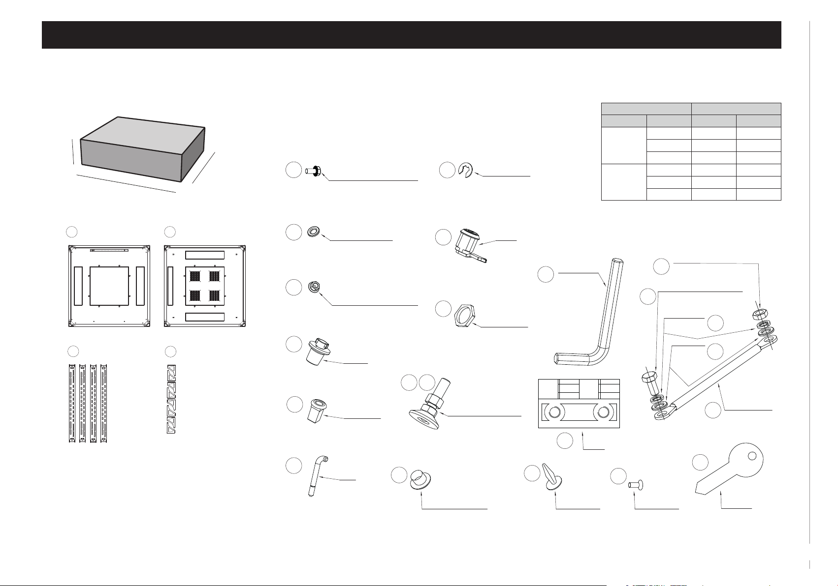
Packaging method, the contents of packaging
F x1
Front door
(the type of
door depends
on the specic
conguration
of the cabinet)
I x2
Side panel
Package 1
120
Package 3
a1
b1
G x1
Rear door
(the type of
door depends
on the specic
conguration
of the cabinet)
55
265
a3
Cabinet’s dimension [mm] Package’s dimension [mm]
height a1, a3
2186 (47U) 2130
2096 (45U) 2040
1963 (42U) 1905
1563 (33U) 1505
1163 (24U) 1105
896 (18U) 850
H x1
3U module panel
with brush strip
(occurs depending
on the type of the door)
J x4
Frame's post
K x4
Mounting prole
Cabinet’s dimensions [mm] Package’s dimension [mm]
width depth b1
1000 930
800
600
800 730
600 730
1000 930
800 730
600 530
2
assembly manual
LC-50
b2
a2
150
a3
265
55
a1
b1
120
Package 2 Package 3Package 1
F x1
Front door
(the type of
door depends
on the specic
conguration
of the cabinet)
G x1
Rear door
(the type of
door depends
on the specic
conguration
of the cabinet)
J x4
Frame's post
K x4
Mounting prole
H x1
3U module panel
with brush strip
(occurs depending
on the type of the door)
I x2
Side panel
a3
265
55
a1
b1
120
Package 3Package 1
* xN - the amount depends on the cabinet’s conguration
Packaging method, the contents of packaging
Package 2
150
b2
a2
6
A x1
Frame's bottom plate
x4
D
x6 (D=1000)
C-prole
(D=600/800)
B x1
Frame's top plate
x8
E
x12 (D=1000, W=800)
Outrigger
(D=600/800, W=800)
7
8
13
14
15
x8 (D=600/800, W=600)
x32 (D=600/800, W=800)
x12 (D=1000, W=600)
x48 (D=1000, W=800)
Screw M6x12 with ange
Tool: socket wrench SW10
xN*
Washer ø6.4
x16 (D=600/800, W=600)
x24 (D=600/800, W=800)
x24 (D=1000, W=600)
x36 (D=1000, W=800)
Nut M6 with ange
Tool: wocket wrench SW10
xN*
Pin
xN*
Insert
xN*
Pivot
35
27
28
xN*
Blanking cap 13/8.5
16
30
20
x4
Adjustable f
Counter nut M12
Tool: wrench 19
xN*
Circlip
xN*
Lock
xN*
Lock’s nut
eet M12x40
34
22
x1
Hex key 8
32
xN*
Hinge
xN*
Mounting rivet
Cabinet’s dimensions [mm] Packege’s dimensions [mm]
width depth a2 b2
1000 805 1005
800
800 805 805
600 805 605
1000 605 1005
600
800 605 805
600 605 605
x4
Nut M5
25
Tool: socket wrench SW8
x4
Screw M5x10
23
Tool: socket wrench SW8
x8
Spring
washer ø5.3
x8
Washer ø5.3
24
26
x4
21
Earthing cable
1333
31
33
xN*
Scr
ew M6x16
x4
Key 1333
3
LC-50
assembly manual
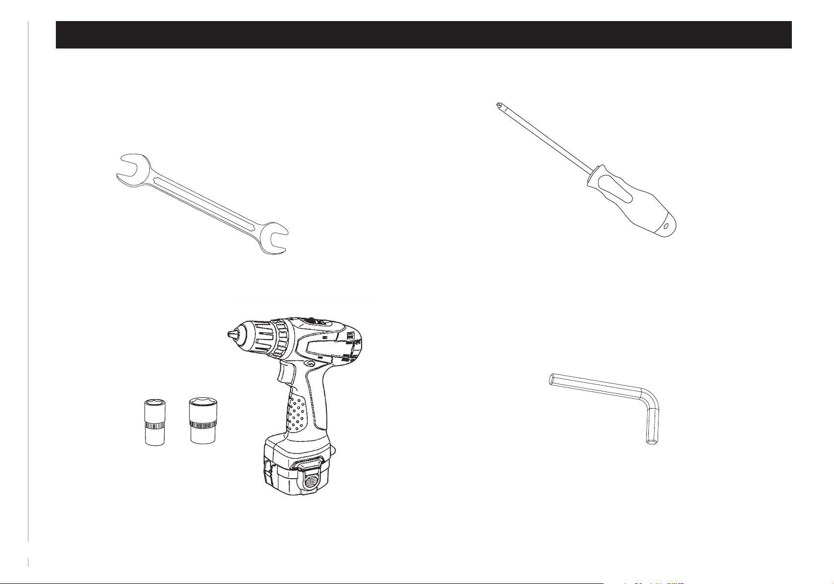
List of necessary tools
Wrench 19 and 27 Screwdriver PH3
Socket wrench SW10 and 8
and electric screwdriver
4
Hex key 8
(supplied with the cabinet
- item no. 22)
assembly manual
LC-50
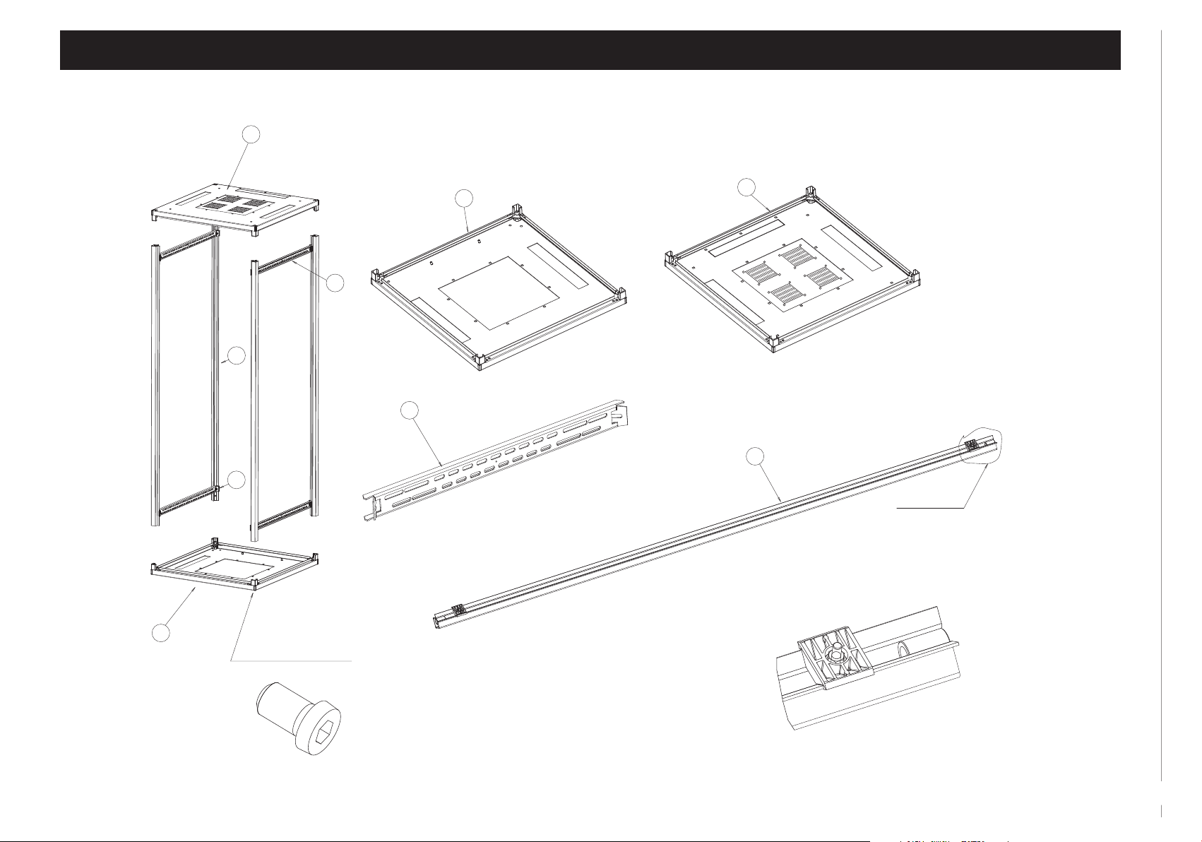
Frame’s assembly - list of elements
B
x1
A
x1
Frame’s bottom plate
B
D
J
D
J
D
Frame’s top plate
See detail A
x4
Frame’s post
Detail A
A
x8 (80 Nm)
Hex-socket screw M12x20
Pre-installed screws in the bottom (A) and the top (B) plate corners
5

LC-50
assembly manual
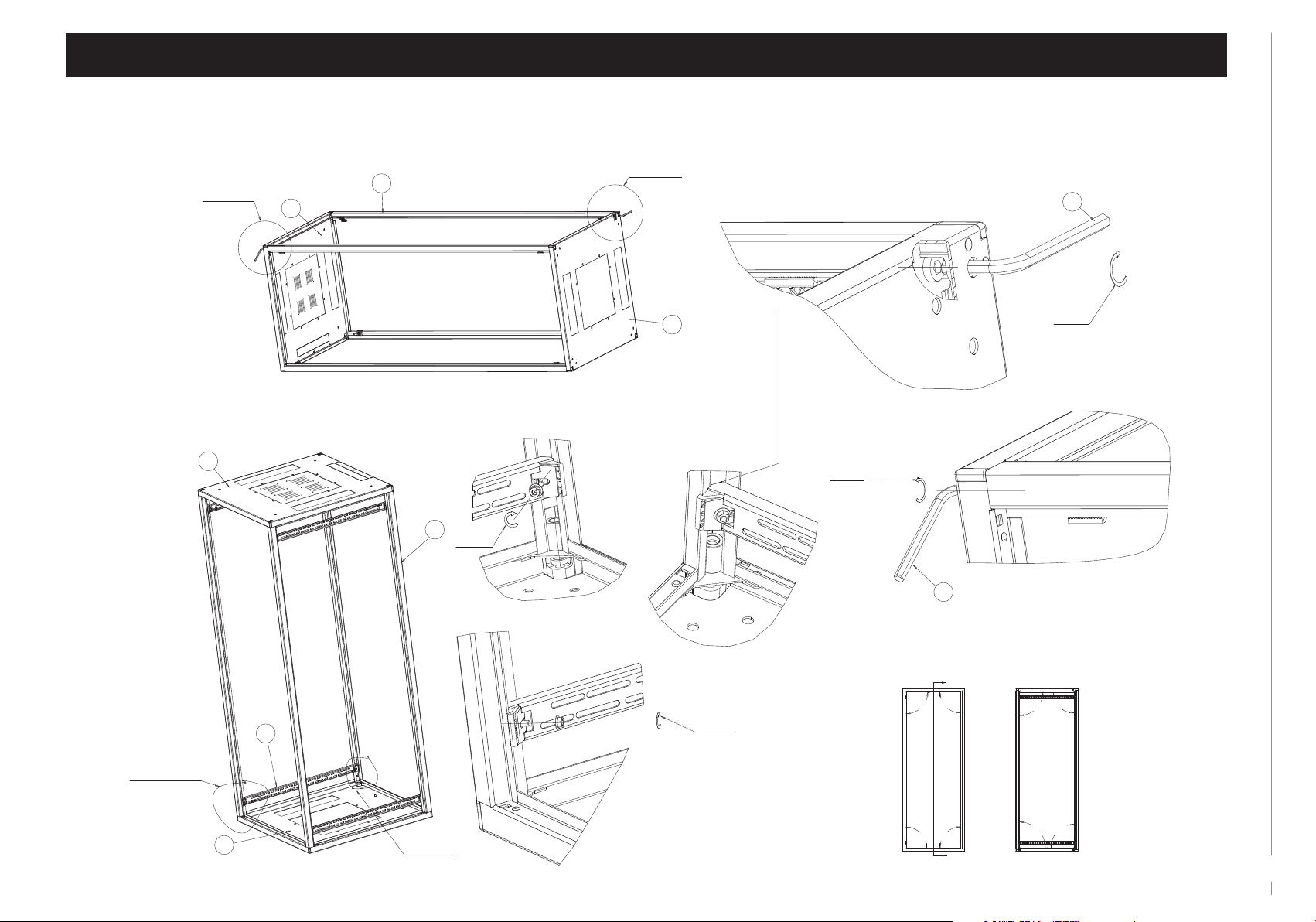
Frame’s assembly - mounting posts to the bottom and the top plate
Step 1
Mounting of the post
to the bottom plate
J
See detail B
A
Detail B
Step 5
Mounting of the top plate
Detail C
See detail C
Step 3Step 2 Step 4
Mounting of the remaining posts
See detail
D
A
A
A
See detail E
See detail F
Detail D
B
Detail F
Detail E
35
6
assembly manual
LC-50
Frame’s assembly - screwing the frame, xing of the C-proles - 600 or 800 mm deep cabinets
See detail G
B
B
Step 7
Step 6
J
Fixing the complete frame
(screwing)
Detail J
J
(4.8 Nm)
Detail I
See detail H
A
Hex key 8
Detail H
Note:
The edges of C-proles (D) have to
touch frame's post (J)
(80 Nm)
Hex key 8
22
22
(80 Nm)
Detail G
See detail I
A
90°
90°
D
A
See detail J
(4.8 Nm)
90°
90°
A
Section A-A
90°
90°
90°
90°
Check
right angles
in the frame
and tight
the screws
in the corners
next.
7

LC-50
assembly manual
Frame’s assembly - screwing the frame, xing of the C-proles - 1000 mm deep cabinets
Step 7a
See detail G
B
J
Only for cabinets:
42U, 45U, 47U
Step 6a
J
B
Fixing the complete frame
(screwing)
Detail J
(4.8 Nm)
Detail I
See detail H
A
Hex key 8
Detail H
Note:
The edges of C-proles (D) have to
touch frame's post (J)
(80 Nm)
Hex key 8
22
22
(80 Nm)
Detail G
Section A-A
90° 90°
90°
90°
Check
right angles
in the frame
and tight
the screws
in the corners
next.
See
detail I
A
90°
X X + 178
D
See detail J
(4.8 Nm)
A
90°
90°
90°
A
8

assembly manual
LC-50
Fixing of the levelling feet and the mounting proles
See detail K
A
Step 8
Fixing of the levelling feet
Detail K
Step 9
Fixing of the mounting proles in 600 mm or 800 mm wide cabinets
See detail M
See detail L
600
Detail M
Detail L
K
6
K
8
(5.2 Nm)
800
Note:
For levelling manual, see page 14.
28
27
(5.2 Nm)
(9.9 Nm)
8
6
E
6
9
LC-50
assembly manual
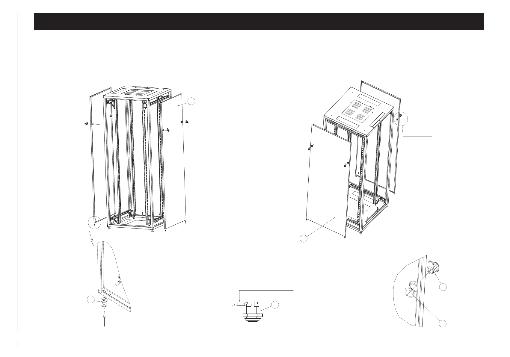
Fixing of the side panels
Step 10
Fixing of the side panels
I
See detail O
10
13
Note: For covers, use locks
with a cam of this shape.
18
I
Detail O
Installation of the locks
in the side panels
30
20

assembly manual
LC-50
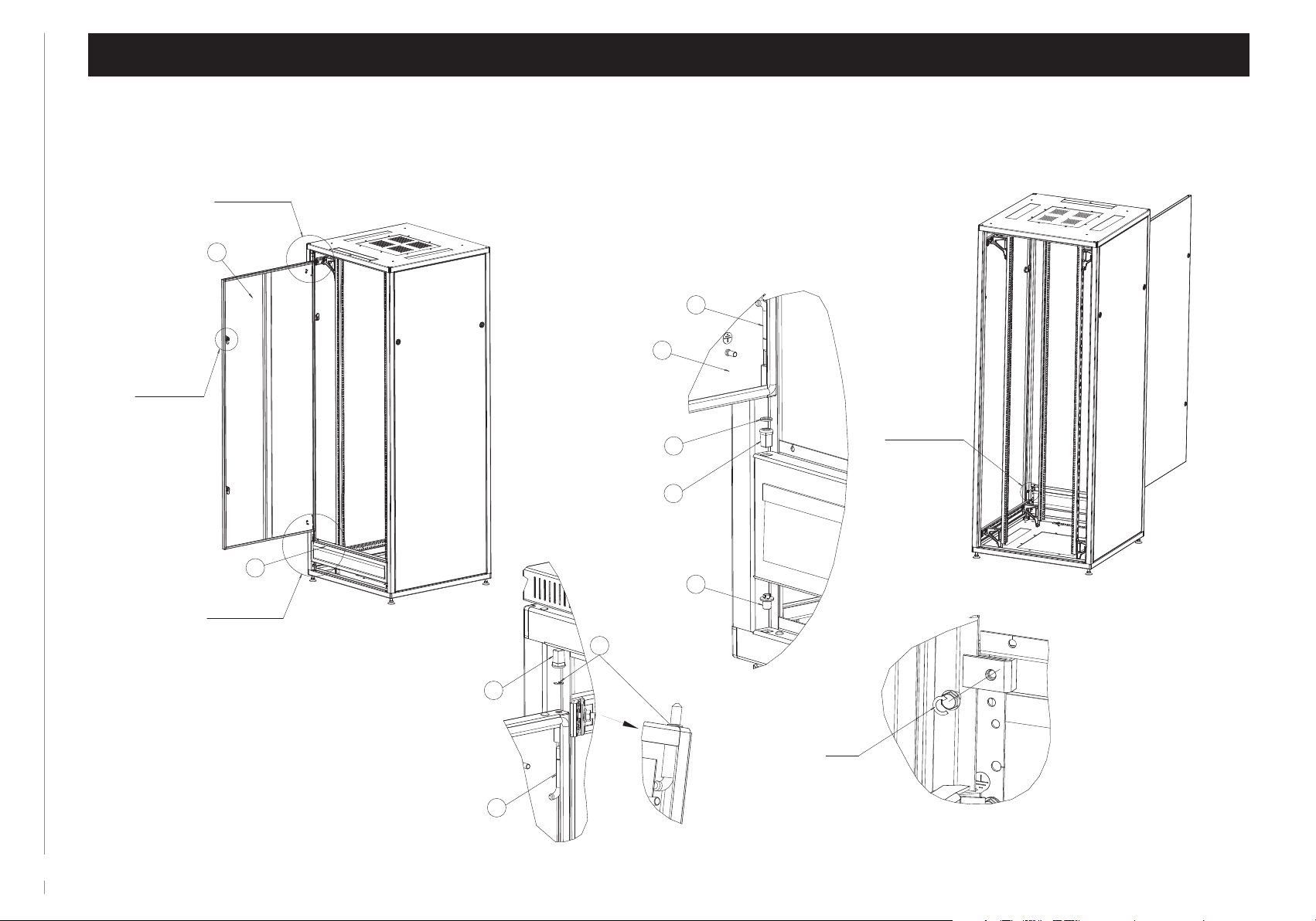
Fixing of the door
Step 11
Fixing of the door with 180° hinges
Detail G
See detail G
See detail H
Detail H
34
14
32
8
33
11
LC-50
assembly manual
Step 12
Fixing of the door
See detail O
on page 10
See detail L
G
See detail J
Fixing of the shortened door with 110° hinges
and the 3U module panel with the brush strip
Szczegół J
15
G
1 or 2 washers
as required
7
14
H
Detail L
13
See detail K
Detail K
12
16
14
9.9 Nm
15

assembly manual
LC-50
11
The doors and the side panels earthing
Step 13
Fixing of the earthing cables
See detail P
See detail O
5
Detail O
Detail P
25
21
The earthing cable
24
26
21
Mounted
to door
or side panel
21
Earthing:
- left side panel
- front door
13
21
Earthing:
- rear door
- right side panel
- 3U module panel
21
23
24
26
Mounted to cabinet's frame
(to earthing the bar or the bottom plate)

LC-50
assembly manual
Levelling the cabinet
Detail Z
Spirit level
Wrench 19
14
See detail Z
1. Level the cabinet using the levelling feet (27) regulation.
2. After levelling the cabinet, tighten the nuts (28)
to the cabinet’s bottom plate.
28
27
 Loading...