

Solar Frontier PowerSet Turbo 2.4-170-1p, PowerSet Mini 2.0-170-1p, PowerSet Turbo 3.0-165-1p, PowerSet Mini, PowerSet Turbo 3.4-170-1p Installation And Operating Manual
...
Solar Frontier Europe GmbH
Installation and Operating Manual
PowerSet Turbo and PowerSet Mini
Installations- und Bedienungsanleitung
PowerSet Turbo und PowerSet Mini
Manuale di installazione e funzionamento
PowerSet Turbo e PowerSet Mini
Installatie- en bedieningshandleiding
ENGLISHDEUTSCHITALIANONEDERLANDS
PowerSet Turbo en PowerSet Mini

Contents
1. General Safety Advice 2
1.1 Safety advice for Solar Frontier SF165-S/SF170-S photovoltaic modules 2
1.2 Safety advice for Turbo inverters 2
2. Proper usage 2
3. Components included and structure of the PowerSet 2
4. About this Manual 3
4.1 Contents 3
4.2 Target audience 3
4.3 Markings 3
4.3.1 Symbols 3
4.3.2 Keywords 3
4.3.3 Markings used in the text 3
4.3.4 Abbreviations 4
5. Installation 4
5.1 Mounting system / substructure 4
5.2 Mechanical installation of Solar Frontier SF165-S/SF170-S
photovoltaic modules 4
5.2.1 Site location 4
5.2.2 Handling instructions 4
5.2.3 Mounting instructions 4
5.3 Electrical installation photovoltaic generator 6
5.3.1 Electrical wiring safety precautions 6
5.3.2 Cabling 6
5.3.3 Grounding 7
5.3.4 Electrical wiring 7
5.4 Installation of Turbo inverters 8
5.4.1 Safety measures during installation 8
5.4.2 Mounting the inverter 8
5.4.3 Preparing the AC connections 8
5.4.4 Preparing the DC connections 9
5.4.5 Prepare the data connection cable required for
using Power Monitoring 9
5.4.6 Connecting a PowerStorage system 9
5.4.7 Modbus RTU data connection cable for connecting an
energy meter 9
5.4.8 Connecting the inverter and switching on the AC power 9
5.4.9 Initial commissioning of the inverter 9
5.4.10 Switching on the DC supply 11
5.4.11 Feed-in management or PowerStorage 11
5.4.12 Registration and configuring PowerMonitoring 11
5.4.13 De-installing the inverter 11
6. Structure and function of the Turbo inverter 12
6.1 Casing 12
6.2 Operating buttons 12
6.3 Overview of operating functions 13
6.4 Service menu 13
6.5 Troubleshooting 14
7. Maintenance 16
7.1 Maintenance of Solar Frontier SF165-S/SF170-S photovoltaic modules 16
7.2 Maintenance DC system 16
7.3 Maintenance of Turbo inverters 16
8. Transport and Storage 16
9. Disposal 16
9.1 Disposal within the EU 16
9.2 Disposal outside the EU 16
10. Technical data and data sheets 16
10.1 Solar Frontier SF165-S/SF170-S photovoltaic modules
10.2 Technical data for Turbo inverter 18
10.3 Technical data AC cable and line circuit breakers 19
10.4 Table of countries 19
10.5 Plugs, sockets, DC cable and Y-cable 22
10.5.1 Product information for plug and socket 22
10.5.2 Product information for DC cable / minimum requirements 22
10.5.3 Product information Y-cable 22
11. Exclusion of Liability 22
12. Contact 22
13. Appendices 23
13.1 AC plug for Turbo inverters 23
13.2 SunClix connectors 26
1
16

1. General Safety Advice
Please ensure all necessary measures are taken to prevent accidents. The use of
PowerSets in applications that may endanger human lives is prohibited, including
in air and road transport systems.
PowerSets must not be used for anything other than their expressed purpose.
Solar Frontier strongly advises you to follow the instructions below in order to
avoid bodily injury, damage to property and/or death.
PowerSets sold by Solar Frontier GmbH may only be installed by authorized
professionals (see 4.2). As soon as it becomes evident that safe operation is
no longer possible (e.g., visible damage), remove the PowerSet immediately
from the grid.
1.1 Safety advice for Solar Frontier SF165-S/SF170-S
photovoltaic modules
• Installation, wiring and maintenance of SF modules must only be carried out
by licensed and trained persons.
• Ensure that all instructions and warnings related to SF modules and all instruc-
tions from the manufacturer of the system components are fully understood
prior to installing and operating a PV solar system.
• The front surface of SF modules should be covered with an opaque material
during installation to decrease the potential of electrical shock.
• SF modules only generate direct current (DC) electricity.
• SF modules do not have the ability to store electricity.
• SF modules will experience higher voltage when connected in series and
higher electrical current when connected in parallel.
• Only interconnect SF modules with similar electrical characteristics in series or
in parallel to prevent system imbalance conditions and module damage.
• The PV array open circuit voltage must never exceed the maximum system voltage
(including in low temperature conditions)
• Excessive leakage currents are a shock and fire hazard.
• Under no circumstances disconnect the cable from operational modules or
electrical arcing may occur. This may result in serious bodily harm or death.
• Do not use SF modules for purposes other than terrestrial power generation to
prevent electrical shock, fire and other accidents.
• Do not artificially concentrate sunlight on modules using lenses or mirrors.
• Do not use light sources other than natural sunlight and general illumination for
power generation.
• Do not use SF modules in water or liquid. Contact with water or other liquid signifi-
cantly increases the risk of electric shock.
• The level of leakage current must be limited in accordance with local regula-
tions for safety reasons.
• Carefully check the polarity of the connections before installing. Incorrect wir-
ing may damage SF modules or appliances.
• Only use tools, plugs, cables and support structures suitable for solar electric
systems.
• Wear appropriate protective clothing when working on SF modules and take
all necessary precautions to prevent electric shock, especially when DC voltage
exceeds 30 V.
1.2 Safety advice for Turbo inverters
• Install and use the device only after reading and understanding this document.
• Always perform the measures described in this document in the sequence
specified.
• Keep this document in a safe place for the entire service life of the device. Pass the
document on to subsequent owners and operators of the device.
• Improper operation can reduce the yields of the photovoltaic system.
• The device must not be connected to the DC or AC cables if it has a damaged
casing.
• Switch the device off immediately and disconnect it from the grid and the
solar modules if any of the following components is damaged:
- Device (not functioning, visible damage, smoke emission, penetration by
liquid, etc.)
- Cables
- Solar modules
• The system must not be switched back on until
- the device has been repaired by the dealer or manufacturer.
- damaged cables or solar modules have been repaired by a technical
professional.
• Never cover the Device.
• Do not open the casing. Danger! This will void the warranty!
• Factory labels and markings must never be altered, removed or rendered
unreadable.
• Observe the respective manufacturer‘s manual when connecting an external
device that is not described in this document (e.g., external data logger). Incorrectly connected components can damage the inverter.
.
Safety advice for the device:
1
1
1
Dangerous voltages can remain present on the components up to 10 minutes
after switching off the DC circuit breaker and the line circuit breaker.
Read and follow the instructions!
2
3
Serial number as a bar code and in plain text
2
3
Figure 1
2. Proper usage
The PowerSet may only be used in grid-connected photovoltaic systems. The
modules, inverter, cables, and connectors have been mutually calibrated for best
performance. The connections may not be grounded.
3. Components included and structure of the
PowerSet
The Solar Frontier PowerSet comprises the following components. The number of
components required can be determined using the list below based on the type
of PowerSet you have:
1
Solar Frontier SF165-S/SF170-S photovoltaic module
2
Solar Frontier Turbo 1P Mini / 1P / 3P1 / 3P2 inverter (incl. inverter, mounting
plate, 1 pair SunClix connectors and AC plug)
3
Y-cables, Version for (+) and (-)
4
DC plugs and DC sockets (3 of each in one pack)
5
Installation and maintenance manual
ENGLISH
2
Area PowerSet Description Capacity Modules Inverters Grid connection Y- cables
15.6 m² PowerSet Mini 2.0-170-1p 2.04 kWp 12 x SF170-S 1 x Turbo 1P Mini 1ph 3 (+) & 3 (-) 3 + 3 3
18.2 m² PowerSet Turbo 2.4-170-1p 2.38 kWp 14 x SF170-S 1 x Turbo 1P 1ph 1 (+) & 1 (-) 3 + 3 7
23.4 m² PowerSet Turbo 3.0-165-1p 2.97 kWp 18 x SF165-S 1 x Turbo 1P 1ph 2 (+) & 2 (-) 3 + 3 6
23.4 m² PowerSet Turbo 3.1-170-1p 3.06 kWp 18 x SF170-S 1 x Turbo 1P 1ph 2 (+) & 2 (-) 3 + 3 6
23.4 m² PowerSet Turbo 3.1-170-3p 3.06 kWp 18 x SF170-S 1 x Turbo 3P1 3ph 2 (+) & 2 (-) 3 + 3 6
26.0 m² PowerSet Turbo 3.4-170-1p 3.40 kWp 20 x SF170-S 1 x Turbo 1P 1ph 3 (+) & 3 (-) 3 + 3 5
27.3 m² PowerSet Turbo 3.6-170-1p 3.57 kWp 21 x SF170-S 1 x Turbo 1P 1ph 2 (+) & 2 (-) 3 + 3 7
31.2 m² PowerSet Turbo 4.0-165-1p 3.96 kWp 24 x SF165-S 1 x Turbo 1P 1ph 3 (+) & 3 (-) 3 + 3 6
31.2 m² PowerSet Turbo 4.1-170-1p 4.08 kWp 24 x SF170-S 1 x Turbo 1P 1ph 3 (+) & 3 (-) 3 + 3 6
31.2 m² PowerSet Turbo 4.1-170-3p 4.08 kWp 24 x SF170-S 1 x Turbo 3P1 3ph 3 (+) & 3 (-) 3 + 3 6
36.4 m² PowerSet Turbo 4.8-170-1p 4.76 kWp 28 x SF170-S 1 x Turbo 1P 1ph 3 (+) & 3 (-) 3 + 3 7
39.0 m² PowerSet Turbo 5.1-170-3p 5.10 kWp 30 x SF170-S 1 x Turbo 3P2 3ph 4 (+) & 4 (-) 6 + 6 6
45.5 m² PowerSet Turbo 6.0-170-3p 5.95 kWp 35 x SF170-S 1 x Turbo 3P2 3ph 4 (+) & 4 (-) 6 + 6 7
54.6 m² PowerSet Turbo 7.1-170-3p 7.14 kWp 42 x SF170-S 1 x Turbo 3P2
62.4 m² PowerSet Turbo 8.2-170-1p 8.16 kWp 48 x SF170-S 2 x Turbo 1P 1ph 6 (+) & 6 (-) 6 + 6 6
Accessories congured for the PowerSets are separately available from Solar Frontier: DC cables, mounting and fastening material, tools for assembly of the cables...
3ph 5 (+) & 5 (-) 6 + 6 7
Plugs &
sockets
Modules
in series
Schematic structure based on
example
PV Generator
Y-Cable
DC-Cable with plug and socket
PowerSet Turbo 3.1
Inverter
Figure 2
4.3 Markings
4. 3.1 Symbols
Symbol
Read manual before using the product. Device
4.3.2 Keywords
Keywords used in conjunction with the symbols described above:
Keyword Description
Danger Immediate danger of death or serious bodily injury
Warning Possible danger of death or serious bodily injury
Caution
Attention Possible damage to property
Advice Tips on operation or usage of the manual
Possible danger of light or medium bodily injury
4.3.3 Markings used in the text
Description Location
General danger warning Manual
Danger from electricity
Manual / device
4. About this Manual
4.1 Contents
These instructions contain all information required by a technical professional for
setting up and operating the inverters.
When installing other components (e.g., AC cable, mounting system) follow the
manufacturer's instructions.
4.2 Target audience
Unless otherwise indicated, the target audiences of this manual are technical
professionals and system operators.
Technical professionals are persons who, for example:
• have the knowledge of terminology and the skills necessary for setting up and
operating photovoltaic systems;
• because of their professional training, knowledge and experience and knowl-
edge of the relevant regulations can assess the following tasks and recognise
possible dangers:
- mounting electrical devices
- assembling and connecting data cables
- assembling and connecting power supply cables.
Markings Description
√ Condition for action
1., 2., 3., ...
cursive light emphasis
bold strong emphasis
Courier
Single step
Several steps in series
Designation of product elements such as buttons.,
displays, operating state
3

4.3.4 Abbreviations
Abbreviation
A
AC
DC Direct current a
Derating Power reduction
DHCP
MSD
RC Residual current
I Current
l
k
I
mpp
kVA Kilovoltampere
kW Kilowatt
kWh Kilowatt-hour(s)
m Metre
2
m
MPP Operating point with the highest output (maximum power point)
MPP tra
Nm Newton metre
P Electrical power
Pa Pascal
PV Photovoltaic
SELV, TBTS,
MBTS
SF Solar Frontier
STC Standard test conditions
U Voltage
U
L
U
mpp
U
PV
V Volt
2
W/m
η Efficiency
Description
Current in amperes
Alternating current voltage
The use of DHCP allows automatic integration of the device into
an existing network (Dynamic Host Configuration Protocol)
Internal mains monitoring for the inverter (mains monitoring
units with allocated all-pole switching devices).
Short circuit current
Current at maximum power point
Square metre
Controls the power of the connected module strings to match the
cker
MPP
Schutzkleinspannung (EN: safety extra low voltage; FR: Très Basse
Tension de Sécurité; ES: Muy Baja Tensión de Seguridad)
Open circuit voltage
Voltage at maximum power point
The generator voltage present at the DC connection (photovol-
taic voltage)
Watt per square metre
5. Installation
Compliance with all relevant national and local laws, regulations and directives, especially for accident avoidance, as well as all relevant technical
standards is mandatory for a safe installation.
5.1 Mounting system / substructure
The PowerSets are delivered in standard form without an assembly system. Solar
Frontier offers a suitable assembly system as a separate accessory. For more information, see: www.solar-frontier.eu. In general, all commonly available mounting
systems which ensure proper mounting following the guidelines in point 5.2.3 are
suitable. Your installer will be able to suggest an appropriate solution.
5.2 Mechanical installation of Solar Frontier SF165-S/
SF170-S photovoltaic modules
5.2.2 Handling instructions
• Do not disassemble or modify SF modules. This may result in an electric shock,
fire or other accidents. Solar Frontier cannot be held responsible for any loss or
damage caused by unauthorized disassembling, modification or misuse of SF
modules.
• Do not drill additional mounting holes into the aluminium frame. Only pre-
drilled holes should be used.
• Avoid placing any stress onto the SF modules, cables or connectors.
(Minimum bending radius of 39 mm (1.54 in) for module cables is recommended)
• Do not stand or step on SF modules. This may result in damage to the module
and/or bodily harm by falling.
• Do not drop SF modules or drop objects onto them. Both sides of the module
(the glass surface and the back sheet) are fragile.
• Do not strike the terminal box or pull the cables. The terminal box can crack
and break, while the output cable may unplug and cause electricity leakage or
an electric shock.
• Do not scratch the back sheet or cables of the SF modules. Rubbing or scratch-
ing may result in an electric shock, electric leakage or an accident.
• Do not scratch the insulation coating of the frame (except for the grounding
connection). This may weaken the strength of the frame or cause corrosion.
• Do not cover the water drain holes of the frame. Doing so may cause frost
damage.
• Do not use glue when closing the cover of the junction box. Similarly, do not
use a sealant to bond the junction box lid to its base.
5.2.3 Mounting instructions
Mounting structures cautions
• Pay attention to the electrochemical series when selecting support structure
material to avoid galvanic corrosion.
• Fasten and lock bolts completely. Inadequate mounting may result in SF modules falling or other accidents.
• Make sure that SF modules have been connected securely to the substructure.
The substructure should consist of durable, rustproof. UV resistant material.
Please adhere to national regulations.
• Ensure that your mounting support structure is designed to withstand the
SF module design snow and wind loads applicable for the chosen site. Solar
Frontier will not be responsible if the SF modules are damaged due to the
durability of the mounting support structure. Please consult your mounting
structure manufacturer.
Mounting the solar modules
• PV modules should typically face south in the Northern Hemisphere and north
in the Southern Hemisphere for optimum power production.
• Modules can be installed horizontally (landscape) or vertically (portrait).
• Maintain a space between SF modules and the roof. This will allow air to circulate, cooling the module, and allow condensation to dissipate. Solar Frontier
recommends a distance of at least 100 mm (3.94 in).
Mounting with clamps
Four or more corrosion-proof clamps should be used to fasten the SF modules to
the support structure securely. The clamps should be secured within the indicated
clamping zones (256 mm +/- 75 mm (10.08 in +/- 2.95 in) from the corners of the
long side of the module) using stainless steel M8 bolts with a minimum length of
20 mm (0.79 in).
All clamps must be at least 30 mm (1.18 in) long and 3 mm (0.12 in) thick and
overlap the module frame by 8 mm (0.31 in) or more.
Clamps must not create shadow nor cover the front glass, and shall not deform
the module frames during installation. For further instructions please contact the
clamp manufacturer.
Maximum load: 2.400 Pa (50 lbs/ft2) to the front and back of the module
ENGLISH
5. 2.1 Site location
• Ensure that the maximum wind and snow loads in local conditions do not
exceed the SF module maximum load ratings.
• Avoid installing SF modules in areas where they are exposed to oil vapour and/
or corrosive gas.
• Avoid accumulation of grit or dust on the SF modules as it may reduce the
output yield.
• Do not expose SF modules to sulphurous atmospheres.
• Do not install SF modules in locations where flammable gases accumulate or
flow as there is a risk of sparks from SF PV modules.
• Do not install SF modules near fire.
• Avoid installing SF modules in locations where they may be covered by perma-
nent shadows.This may adversely affect their performance.
• Do not install SF modules in locations where temperatures exceed the tem-
perature range indicated in the module’s technical specifications.
4

Module perpendicular to support rails
75 mm 75 mm (2.95 in)
75 mm
75 mm (2.95 in)
75
mm
75
mm
75
mm
75
mm
75
mm
75
mm
745
mm
256
mm
75
mm
75
mm
Array Installation (section)
ape (
(10 0
(29.
(10.08 in)
Ar
L
Middle clamp
End clamp
95 in)
75
75 mm 75 mm (2.95 in) 75 mm 75 mm (2.95 in)
256 mm 745 mm
(10.08 in)
Cross section of an array
Module parallel to support rails
(2.95 in) (2.95 in)
(29.33 in)
Landscape (horizontal) Portrait (vertical)
3 mm
(0.12 in)
End clamp
Module
Module
8mm
(0.31 in)
Clamp to module overlap
min 8 mm (0.31in)
Bolt
Nut
Module
support rail
8 mm
Module
(0.31 in)
Module
Middle clamp
3 mm
Module
(2.95 in)
(2.95 in)
(10.08 in) (29.33 in)
Figure 3
(0.12 in)
Figure 4
75 mm
75 mm (2.95 in)
Cross section of an array
75 mm 75 mm (2.95 in)
256 mm
(10.08 in)
745 mm
(29.33 in)
3 mm (0.12 in)
75 mm 75 mm (2.95 in)
75 mm (2.95 in) 75 mm
75 mm (2.95 in) 75 mm
75 mm (2.95 in)
75 mm
Module
8 mm (0.31 in)
Module Module Module
Clamp to module overlap,
min 8 mm (0,31 in)
8 mm (0.31 in)
For alternative mounting methods please consult Solar Frontier.
Nut Nut
10 mm
(0.39 in)
Bolt
Module
support rail
Module to rail overlap,
min 10 mm (0.39 in)
10 mm
(0.39 in)
Module
75 mm (2.95 in) 75 mm
745 mm
(29.33 in)
75 mm 75 mm (2.95 in)
256 mm
3 mm (0.12 in)
Figure 5
Figure 6
5

5.3 Electrical installation photovoltaic generator
5. 3.1 Electrical wiring safety precautions
• The sum of Voc of modules in series must not exceed the maximum system voltage of the module under any condition. Reverse current applied to the modules
must not exceed 7 A
• Do not touch or handle the PV module, terminal box or the end of output
cables with bare hands.
• Do not carry out installation when PV modules, installation tools or installation
area are exposed to water.
• Ensure that the connection parts between SF modules and power receiving
devices are isolated and waterproof. Using SF modules with insufficient isolation and waterproofing could result in an electric shock, an electric leak or an
accident.
• Keep the junction box and connecting cables away from any liquids until the
connectors are mated. Failure to do this may cause faulty wiring.
• The connecting components between the modules must be compatible
with the connecting system. They must enable them to work perfectly and
completely safely.
• Inverters must meet the technical requirements of SF modules.
• Do not connect the PV modules directly to loads such as motors. Variation in
output power may damage the motor.
• Observe and understand the safety instructions of batteries. Their misuse can
result in serious bodily harm due to high electrical current.
• Cables should be adequately protected from damage by wildlife.
5.3.2 Cabling
Solar Frontier places great value on delivering as many components as possible
pre-assembled in order to help avoid sources of error.
As each roof and PV installation has its own peculiarities, certain cables have to be
adapted on site to the system and assembled accordingly. For example, the cables
for extending the connecting cables to reach the inverter have to be assembled
on site. In addition, if there are obstructions on the roof (e.g. dormers) it may be
necessary to bridge the increased distance with extension cables. The DC cable,
sockets and plugs which are included in the PowerSet are for this purpose.
An Hosiden crimping tool (HSC2009-530030) is also required for crimping the
contacts. This is not included in the PowerSet. Pre-assembled connecting cables
must not be altered.
Please ensure a clean and proper assembly of the cables to avoid error
sources and to ensure safe cabling.
The DC cables used must comply with the requirements specified in Section 10.5.2
and be compatible with the plug-in connectors provided by Solar Frontier. Solar
Frontier recommends the use of the DC cables as specified in Section 10.5.2. These
are available from Solar Frontier.
The following tools are required to assemble the cables:
- Mounting key (not included in the delivery)
- Crimping tool for twisted contacts (not included in the delivery)
- Insulation stripping pliers (not included in the delivery)
Shortening and stripping the insulation from the DC cable
First, the cable has to be shortened to the proper length. Then the outer insulation
is removed with suitable insulation stripping pliers to a length of 6.5-7.5 mm.
Please take care not to damage the wires in the DC cable. This could reduce
the cross section and cause electrical faults.
.
Crimping the twisted contacts
Figure 9
Crimping
pliers
Fig ure 10
Fi gu re 11
Fi gur e 12
Fig ure 13
The HSC2010 positioning aid is
used for crimping the pins.
Positioning aid HSC2013 is used for
crimping the contacts.
Place the contact or pin in the position for the respective cross-section.
ENGLISH
Place the crimping sleeve completely into the tool as shown in
Figure 11.
Do not close the crimping pliers
completely at first.
Close the tool gently and check
whether the crimping sleeve is
properly positioned in the crimping
die.
Guide the stripped end of the cable
fully into the crimping sleeve.
Then close the tool completely
while holding the cable until the
locking device has been triggered.
Check the crimping result and the
correct fit of all cable strands.
Positioning
aid
Figure 7
Figure 8
Adjust the tool:
1. Lift the positioning aid
2. Turn the positioning aid by
±120° in the desired direction
Fig ure 14
Guide the crimped contact into the
connector until it perceptibly clicks
in and locks.
Gently pull at the cable to check
whether the contact holds firmly
Connector
Contact
and has locked.
Take note that the pin may not
be inserted into the connector.
Guide the crimped pin into the
socket until it perceptibly clicks in
and locks.
Gently pull at the cable to check
Socket
Pin
Fig ure 15
whether the pin holds firmly and
has locked.
Take note that the contact may
not be inserted into the socket.
6

good
not good
5.3.3 Grounding
Fasten the sealing caps with a
fastening torque of 1.7 Nm.
Check that there is no gap
between the sealing cap and the
connector or socket.
Fig ure 16
Grounding cautions
Fi gur e 17
• Be aware of the necessary grounding requirements prior to installation. Your local
authorities can help you further.
• Install arrestors, surge absorbers or any other appropriate lightning protection tools
as needed.
• Module frames, mountings, connection boxes and metal conduits should be
connected to an earth ground as lightning protection, in accordance with local,
regional and national standards and regulations.
• Holes (d 4 mm, 0.16 in) are provided in the aluminium frame of the SF module to
accommodate grounding. The grounding cable must be attached to the module
frame with a screw and washer. There must be an electrical contact. Use a copper
grounding cable with a cross section of at least 2 mm² (AWG14) and a temperature
range of at least -40 to 85 °C.
• Alternatively, it is possible to use grounding lugs with integrated grounding pin,
lock washers and grounding clips or brackets for PV modules as per NEC Section
250. These components must be used in compliance with the grounding device
manufacturer's guidelines. Consult the grounding device manufacturer to identify
the appropriate grounding and bonding device for your mounting structure or
design.
Grounding (IEC)
Rolling Thread Screw
Grounding Cable
Lock Washer
For alternative grounding methods please consult Solar Frontier.
Connect the grounding cable to the point marked with the electrical earth symbol
Please refer to further instructions provided by the screw or bolt manufacturer.
.
Crimping Terminal
PV module frame
5.3.4 Electrical wiring
• The SF modules have a connecting cable with one plug for each pole. Use these to connect the module.
• Do not open the junction box.
• Fasten the module cable to the frame or to the mounting system in order to avoid any stress to the connector.
• Cables drooping from the terminal box are hazardous and must be avoided.
• Cables should be secured so they are not exposed to direct sunlight (such as behind the module).
• The sum of Voc of modules in series must not exceed the maximum system voltage rating of the module under any condition, even at low temperature.
• Reverse current applied to the modules should not exceed 7 A under any condition.
• Minimum cable diameter: 2.5 mm² (0.004 in²).
Fig ure 18
Series connection
Junction box
Parallel connection
Fig ure 19
Carry out installation and wiring work in compliance with all relevant health, safety and environment laws and regulations.
Diagram showing standard module cabling with obstruction
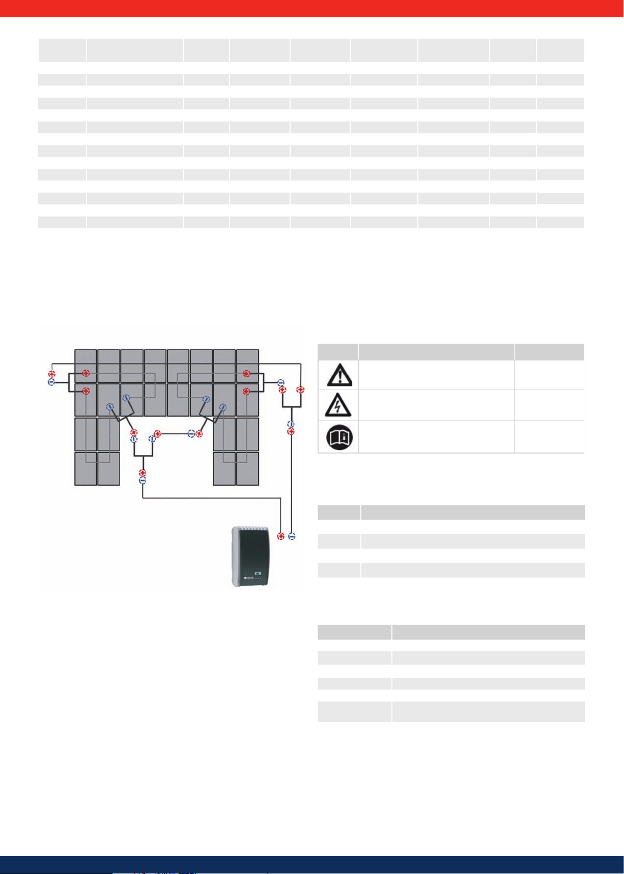
If obstructions make it impossible to connect modules directly side-by-side, the plugs and sockets provided can be used to bridge gaps. A simple example is shown in
Figure 20:
Roof window
Extension Cab le
Figure 20
7

5.4 Installation of Turbo inverters
2
3
1
1
5.4.1 Safety measures during installation
Observe the following safety notes when performing the work described in section Installation.
Danger
Risk of death by electrocution
• Only technical professionals may perform the work described in section Installation.
• Always disconnect all DC and AC cables as follows before starting work on the inverter:
1.
Turn the AC circuit breaker to off. Take measures to prevent the system from
being unintentionally switched on again.
2. Set the DC circuit breaker on the inverter to position 0. Take measures to
prevent the system from being unintentionally switched on again.
3.
Disconnect the Hosiden connectors of the DC cables according to
the manufacturer's instructions. A special tool is required for this.
Warning: DC cables are under current if light falls on the modules.
4. Remove the AC plug from the inverter as described in section 5.4.13.
5.
Check that all pins of the AC plug are free of voltage. Use a suitable voltmeter
for this (do not use a simple neon phase checker).
• Do not connect cables to the inverter until explicitly asked to do so in the
instructions.
• Do not open the casing of the inverter.
• Connect only SELV circuits to the RJ45 sockets.
• Lay the cables such that the connection cannot come loose accidentally.
• When laying cables, ensure that no damage occurs to any of the constructional
fire safety measures in the building.
• Make sure that no flammable gases are present.
• Observe all applicable installation regulations and standards, national laws and
connection values specified by the regional power supply company.
Attention
Danger of damage to the inverter or derating!
• The mounting location must satisfy the following conditions:
- The mounting surface and the immediate environment are stationary,
vertical, level, flame retardant and not constantly vibrating.
- They meet the requirements for environmental conditions; see 10.2. Technical
data for Turbo inverter.
- The inverter has the following clearances around it:
above/below: at least 200 mm
to the sides/in front: at least 60 mm
• Do not install the inverter in areas where animals are kept.
• Observe the connection ratings specified on the type plate.
• The DC cables must not be connected to an earth potential (DC inputs and AC
output are not galvanically isolated).
Attention
When transmitting data over a public network:
• Transmitting data over a public network can incur additional costs.
• Data transmitted over a public network is not protected from access by third
parties.
Advice
• Avoid exposing the inverter to direct sunlight.
5.4.2 Mounting the inverter
Fastening the mounting plate
Screw the mounting plate to the mounting surface using 4 screws:
• Use screws (and dowels etc.) appropriate for the weight of the inverter.
• The mounting plate must lie flat on the mounting surface and the metal strips
at the sides must point forwards (Figure 22 ).
• Install the mounting plate vertically with the retaining plate 1 at the top (Figure 22).
1
Figure 22
Fig ure 21
Mounting the inverter on the mounting plate
1. Pick up the inverter by its handles 1 or edges, place it in the middle of the
mounting plate 1 and press in gently 2 (Figure 23).
2. Lower the inverter 3 until the retaining plate on the mounting plate clicks
audibly into place.
The hooks on the back of the inverter must pass over the lugs on the mounting plate.
3. The inverter must be firmly seated on the mounting plate and it must not be
possible to push it upwards.
Advice
The procedure for removing the inverter from the mounting plate is described in 6.4.9
5.4.3 Preparing the AC connections
Line circuit breaker
Information on the required line circuit breaker and the cables to be used between
the inverter and the line circuit breaker is provided in chapter 10.3.
Residual current circuit breaker
If the local installation regulations require the installation of an external residual
current circuit breaker, then a Type A residual current circuit breaker as per
IEC 62109-1, Section 7.3.8. is sufficient.
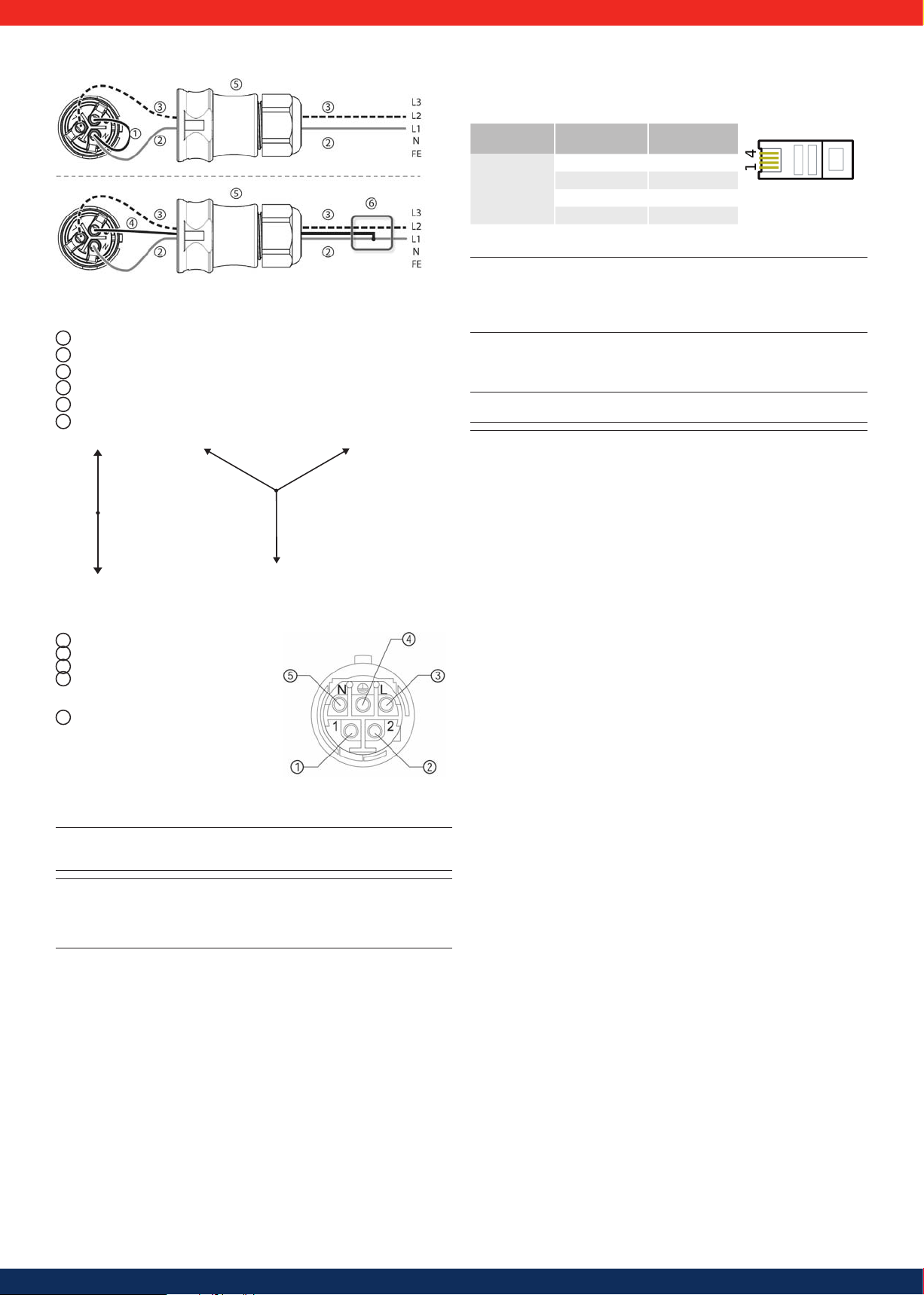
Wiring the AC plug
Danger
Risk of death by electrocution! Observe the warning notes in 5.4.1!
Grid voltage 220 V ... 240 V
Wire the AC plug supplied as described in 13.1.
Grid voltage 100 V ... 127 V
Danger
Risk of death by electrocution! Never connect one of the phases L1, L2 or L3 to PE
or N on the mains grid side.
Advice
If the grid voltage is between 100 V and 127 V, the inverter can be connected
between the external conductors L1, L2 and L3 as follows:
2-phase mains grids
• N and L are connected between the L1 – L2 external conductors on the
inverter side. See 2 and 3 in Figure 24.
• One of the two connected external conductors is connected to PE at the
inverter side. This connection can be made within the AC plug or in an external
junction box.
• Figure 24 shows an example of an inverter-side connection between L1 and PE:
Top: Connection
Bottom: Connection
3-phase mains grids
• N and L are connected between the L1 – L2 or L1 – L3 or L2 – L3 external
conductors on the inverter side.
• Connect the external conductor on the inverter side to PE: as above.
• Figure 24: as above.
The external conductor voltages are shown in Figure 25.
1. Wire the AC plug supplied to match the selected external conductors, as
described in chapter 13.1. Do not yet close the AC plug.
2. Connect one of the two connected phases to PE at the inverter side. Make this
connection inside the AC plug or use an external junction box; see Figure 24.
1
in the AC plug 5
in an external junction box 6
4
ENGLISH
Figure 23
8
41
L
2
L
3
L
1
N
100 - 127 V
100 - 127 V
100 - 127 V
L
1
L
2
N
100 - 127 V
100 - 127 V
Only for the Turbo 1P Mini and Turbo 1P inverter:
Figur e 24
Connect ing N and PE
in the AC plug (t op)
or distri bution box (bo ttom)
1
Connecting cable between N and PE with the connection point inside the AC plug
2
External conductor L1
3
External conductor L2
4
Connecting cable between N and PE with the connection point in the junction box
5
Casing of the AC plug
6
Junction box
Figure 25
External conductor voltages
in 2 and 3 pha se grids with
100 V ...127 V
Only for the Turbo 3P1 / 3P2 inverter:
Wire the AC plug provided as described in the following Figure.
1
Phase 1
2
Phase 2
3
Phase 3
4
As the inverter is protection class II.
Figure 26
the PE protective conductor has no
function and need not be connected.
5
Neutral conductor
5.4.4 Preparing the DC connections
Danger
Risk of death by electrocution!
Use the SunClix connectors provided to maintain the specific protection class.
Attention
Danger of damage to the inverter and modules.
Connect the mating parts matching the DC connectors to the DC cable with the
correct polarity.
The Hosiden mating parts to the DC cable as per the instructions in section 5.3.2.
5.4.5 Prepare the data connection cable required for
using Power Monitoring
Provide an RJ45 standard cable (patch cable Cat5) to use the on-line Power Monitoring service or provide an alternative data connection cable as required.
5.4.6 Connecting a PowerStorage system
The initial operation and configuration of the PowerSet can be completed according to these instructions when a PowerStorage system is used.
Thereafter, commission the PowerStorage system as described in the instructions
provided for this purpose. They describe all the necessary adjustments for the
PowerSet in detail.
5.4.7 Modbus RTU data connection cable for connecting
an energy meter
A 4-pin telephone cable with RJ10 connector on the inverter side can be used as a
data connection cable to connect an energy meter for feed-in management.
Device
Connection
Inverter
RJ10
Signal
Contact 1 Data A
2 Data B
3 Ground
4 —
Figur e 27
Contact a llocation (= wi re number) of the R J45 connector
Advice
• Material damage due to electrical voltage! The alternative data connection
cable may only be produced by a specialist.
• Risk of destroying the Modbus RTU input of the inverter. Contact 4 of the RJ10
socket carries voltages < 20V. Do not use this contact.
5.4.8 Connecting the inverter and switching on the AC power
Danger
Risk of death by electrocution! Observe the warning notes in 5.4.1.
Attention
Maintain a minimum clearance of 200 mm (7.87 in) between the data connection cables (RS485/Ethernet) and the DC /AC cables to prevent data transmission
interference.
• Before connecting the PV system to the grid, ensure that the complete system
has been checked, tested and approved in accordance with the relevant
regulations.
• Depending on local regulations, only accredited personnel may connect the
PV system to the grid and commission it.
1. If necessary, establish a data connection.
2. Push the Amphenol Helios H4 opposing connector of the DC cable firmly
into the DC connection of the inverter until it audibly clicks into place.
3. Insert the AC plug into the socket on the inverter until it audibly clicks into
place.
4. Switch on the AC line circuit breaker. The start page for initial commissioning
is shown on the display.
5. Perform initial commissioning and switch on the DC supply, as described in
5.4.9 and 5.4.10.
5.4.9 Initial commissioning of the inverter
Conditions for starting initial commissioning
Initial commissioning starts automatically when at least the AC connector has
been installed and switched on as described previously, If initial commissioning is
not fully completed, then it starts anew the next time the device is switched on.
Guided initial commissioning
Initial commissioning is a guided procedure that sets the following information:
• PowerSet
• Display language
• Date / Time
• Country
• Reactive power characteristic curve (if prescribed for the selected country)
Setting the country
The following applies when setting the country:
• The set country must always be the same as the country where the inverter is
installed. This causes the inverter to load the prescribed grid parameters for the
selected country. More information on this is provided in the table of countries
in section 10.4.
• The country can only be set once!
• If you have selected the wrong country, contact your installer or Solar Frontier.
• If you cannot select your country on the inverter, contact your installer or Solar
Frontier.
• The country setting does not affect the language used on the display. The
display language is set separately.
9

Operation
Starting initial commissioning
Language
√ The check list for initial commissioning is
displayed.
• The PowerSet entry is selected.
• The checkboxes are not selected.
Advices
• When a check list item is called up the corre-
sponding checkbox is automatically selected.
• The following items are only displayed if the
use of a reactive power characteristic curve
is prescribed for the country selected in the
Country item:
• – Reactive power characteristic curve
(reactive power characteristic curve type)
– Number of nodes
1)
– Node 1
1)
– Node 2
1) 2)
– Node n
– Display characteristic curve
1)
: Only displayed for reactive power character-
istic curve type Enter characteristic curve.
2)
: Only displayed if Number of nodes has
1)
been set to a value > 2.
• Initial commissioning is completed by calling
up the Finish item.
• Finish can only be performed when all other
checkboxes are selected.
1. Press to select a check list item.
2. Press SET to call up the item.
The items are described separately below.
1. Press SET. The first digit of the PowerSet
code flashes.
2. Press to change the first digit of the
PowerSet code.
3. Press SET. The change is adopted.
4. Press . The second digit of the PowerSet
code is highlighted.
5. Repeat steps 1 to 3 for the second digit of
the PowerSet code.
6. Press ESC. The check list is shown.
1. Press to select a display language.
2. Press SET. The language is adopted.
3. Press ESC. The check list is shown.
Time
1. Press SET. The hour display flashes.
2. Press to change the hour.
3. Press SET. The change is adopted.
4. Press . The minutes are selected.
5. Repeat steps 1 to 3 for the minutes.
6. Press ESC. The check list is shown.
Country selection
Advice
The country can only be set once!
1. Press to select a country.
2. Press SET.
3. Press ESC. The dialogue shown on the left is
displayed.
4. Press ESC to select a different country by
performing steps 1 and 2 or press
SET for a longer period of time (> 1 s) to
confirm the currently selected country. The
check list is shown.
Reactive power characteristic curve
1. Press ESC to call up this point.
2. to mark one type of reactive power
characteristic.
3. Press SET. The reactive power type is accepted.
4. Press ESC. The check list is shown..
Advice
is shown when "cosPhi = 1" was not selected.
1. Press , to mark Load Templates.
2. Press SET.
3. Press , to select a standard characteristic.
4. Press SET.
Standard characteristic is accepted.
5. Press ESC. The check list is shown.
ENGLISH
: An additional Load Templates menu point
Date format
Date
Time format
1. Press to select a date format.
2. Press SET. The date format is adopted.
3. Press ESC. The check list is shown.
1. Press SET. The date flashes.
2. Press to change the day.
3. Press SET. The change is adopted.
4. Press . The month is selected.
5. Repeat steps 1 to 3 for the month.
6. Press . The year is selected.
7. Repeat steps 1 to 3 for the year.
8. Press ESC. The check list is shown.
1.
Press to select a time format.
2.
Press SET. The time format is adopted.
3. Press ESC. The check list is shown.
Number of nodes
Node n
Display characteristic curve
10
1. Press SET. The value flashes.
2. Press to change the number of nodes.
3. Press SET. The value is adopted.
4. Press ESC. The check list is shown.
1. Press to select a parameter for the node.
Advice: P% cannot be changed at the first and last
nodes (000%.100%).
2. Press SET. The parameter value flashes.
3. Press to change the value.
4. Press SET. The change is adopted
.
5. If necessary repeat steps 1 to 4 for the other
parameters.
6. Press ESC. The check list is shown.
1. The previously set reactive power characteristic
curve is displayed graphically (example in Fig.
left).
2. Press ESC. The check list is shown.
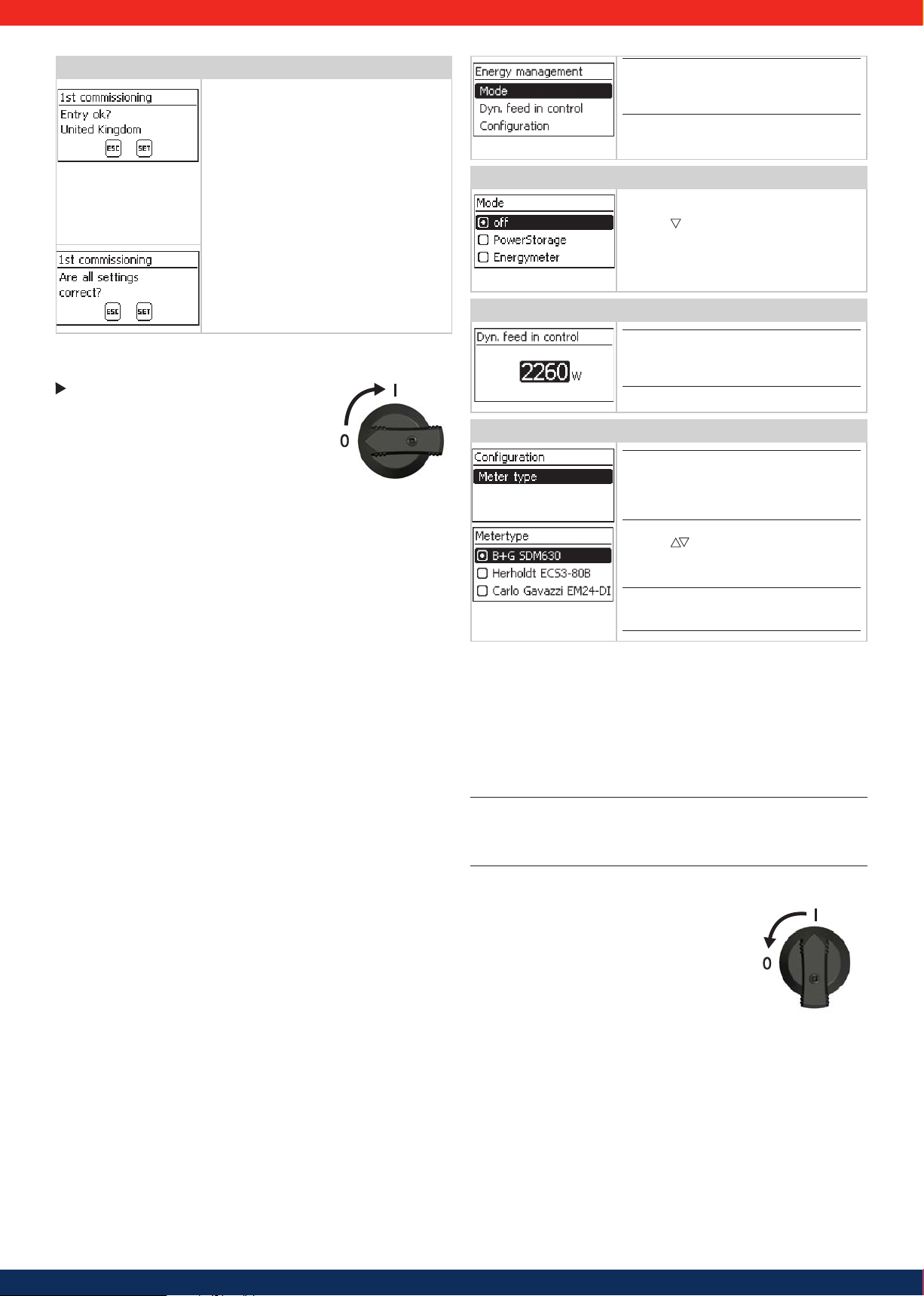
Finish
√ Finish has been selected in the check list
and SET has been pressed.
One of 2 possible dialogues is displayed.
Advice:
The settings regarding the feed-in management must be provided in the energy management sub-menu.
1. Proceed as follows, depending on the dialogue
• Dialogue Settings are incomplete: Press SET and
work through the open items in the check list.
• Dialogue Are all settings correct?
Press ESC to correct settings or press
SET for a longer period of time (> 1 s) to finish
initial commissioning.
2. If SET is pressed for a longer time then the
inverter restarts and synchronises itself with
the grid (Fig. left).
.
5.4.10 Switching on the DC supply
Set the DC circuit breaker on the inverter to position I
(Figure 31). After testing via the internal MSD (approx.
2 minutes), the power fed into the grid can be shown on
the display (assuming that sunlight is present).
Figure 28
5.4 .11 Feed-in management or PowerStorage
Feed-in management or PowerStorage
It is also possible to use an energy meter for feed-in management. It must be connected to the Modbus RTU interface and comply with the following requirements:
The inverter communicates with energy meters through the Modbus RTU. The
following applies:
• Only energy meters that were pre-programmed in the inverter can be used.
• The pre-programmed energy meters are:
• Herholdt ECS3, item number: ECSEM72
• Janitza ECS3, item number: ECSEM68MID
• B+G SDM630, item number: 1141103
• Carlo Gavazzi EM24, item number: EM24-DIN.AV9.3.X.IS.X
• The energy meter must measure in positive direction relative to the mains
network. Take note of the manufacturer's instructions
This menu point can alternatively be used to activate the PowerStorage function
when a Solar Frontier battery system is used. Details are provided in the PowerStorage manual.
Modus
1. Press SET to call up this point.
2. Press to mark the energy meter or to
activate PowerStorage.
3. Press ESC.
4. Press ESC to move up one level to energy
management.
Dynamic feed regulation
Advice:
The power fed into the mains network is set
in 10 W steps.
It can be limited to a minimum of 0 W.
Conguration energy meters
Advice:
The inverter can only work with energy meters that have already been pre-programmed
in the inverter. The pre-programmed energy
meters are listed under Meter Type.
1. Press SET to call up this point.
2. Press to mark the meter type.
3. Press ESC
4. Press ESC to leave the sub-menu.
Advice
The connection to the energy meter can be veried with a connection test.
.
:
5.4.12 Registration and conguring PowerMonitoring
The registration and the monitoring set-up can be performed once commissioning has been completed.
Please follow the link to be found on the sticker attached to the front of the device
housing. Follow the guided registration process to its end. Additional information
regarding registration can also be found at this link.
5.4.13 De-installing the inverter
Danger
Risk of death by electrocution!
Only technical professionals may perform the work described in section
De-installing the inverter.
Observe the warning notes in 5.4.1.
Switching o AC and DC supplies
1. Turn the AC circuit breaker to off.
2. Set the DC circuit breaker on the inverter to position 0
(Figure 29).
Figure 29
11

Disconnecting DC connections from the inverter
3
1
2
4
Disconnect DC cables according to the manufacturer's instructions. A special
tool is required for this.
Warning
DC cables are under current if light falls on the modules.
Disconnecting the AC plug from the inverter
For the Turbo 1P Mini / 1P inverter:
1. Remove the AC plug from the socket on the inverter as described in chapter 13.1.
2. Check that all pins of the AC plug are free of voltage. Use a suitable voltmeter for
this (do not use a simple neon phase checker).
For the Turbo 3P1 / 3P2 inverter:
1. Disconnect the AC plug from the inverter: gently press in the ratchet near the
front of the AC plug with a suitable object to unlock it, and remove the plug.
2. Check that all pins of the AC plug are free of voltage. Use a suitable voltmeter for
this (do not use a simple neon phase checker).
Opening the AC plug (only if required)
For the Turbo 1P Mini / 1P inverter:
Open the AC plug as described in the Appendix under Mounting > AC plugs.
For the Turbo 3P1 / 3P2 inverter:
Open the AC plug: First open the cable gland at the back and then push in the
ratchets on the left and right of the plug casing (simultaneously) and unlock
with a suitable tool. Then remove the upper part of the casing from the contact part.
6. Structure and function of the Turbo inverter
6.1 Casing
ENGLISH
Removing the inverter from the mounting plate
1. Use one hand to press the retaining plate on the mounting plate approx.
5 mm (0.20 in) towards the mounting surface 1 (Figure 30).
2. Use the other hand to push the inverter upwards, far enough so that the
retaining plate no longer latches.
3. Lift the inverter with both hands until the hooks on the rear side of the inverter
4. Remove the inverter from the mounting surface
are free
3
Release the retaining plate.
2
4
Figure 30
Figure 31
1
Hood
Display (monochrome, 128 x 64 pixels)
2
Type plate, Serial number, warning notices
3
Operating buttons: ESC, , , SET (from left to right)
4
1x AC connector
5
1x DC connector plus (+) for solar modules
6
(Phoenix Contact SunClix, insulated)
7
1x DC connector minus (−) for solar modules
(Phoenix Contact SunClix, insulated)
DC circuit breaker
8
(interrupts plus and minus inputs simultaneously)
9
2x RJ45 sockets (RS485 bus)
1x RJ45 socket (Ethernet)
10
1x RJ10-socket (Modbus RTU)
11
The casing components are described in detail below.
6.2 Operating buttons
The operating buttons (4 in Figure 31) have the following functions:
Button Action Function general Guided conguration
jumps up by 1 menu level navigates 1 step
discards any changes
jumps to status display
• moves the highlighted bar or the content of the
display up
• moves the highlighted position in a numerical setting
one digit to the left
• increases a setting by one step
• moves the highlighted bar or the content of the
display down
• moves the highlighted position in a numerical setting
one digit to the right
• decreases a setting by one step
jumps down 1 menu level
• a selected numerical value begins to flash and can be
altered
• adopts any changes
• alters the state of a control (checkbox/radio button)
answers a query dialogue with yes
jumps to the start of the
guided configuration process
–
navigates 1 step forward
Table 1
ESC
SET
Press
briefly
Press longer
(≥ 1 second)
Press
briefly
Press
briefly
Press
briefly
Press longer
(≥ 1 second)
12

6.3 Overview of operating functions
For the sake of clarity, only the operating buttons and SET are illustrated.
Status
display
Output power
Current day
yield *)
PV voltage *)
PV current *) Meas. values
Grid voltage
Grid current
Grid
frequency
SET SET SET
*)
*)
Main menu
Yield
Remuneration
*)
Self
consumption *)
Autarky level *)
Settings
Self test *)
Gener. ch.
curve
Daily
SET
SET SET
SET SET
SET
Monthly
Annual
Total
Time/date
Remuneration
*)
Energy
management *)
Reset max.
vals.
Clear
event log
Submenus
Mode *)
Dyn. feedin
control *)
RS485
address *)
Configuration
*)
DHCP
IP addressLanguage
off *)
PowerStorage
*)
Energy
meter *)
Meter type *)
Reactive
power *)
Internal
temp.
*)
Derating *)
Max. daily
power *
)
Abs. max.
power *)
Day max.
yield
*)
Operating
)
hours *
Total yield *)
Event log
Information
SET
Contact info
System info
Country
setting
React. pwr.
char. curve *)
Self test *)
Network
Contrast
RS485
address *)
Network
Alarm
Backlight
Service
SET
SET
Subnet
mask
Gateway Voltage limits
DNS
Web portal
Del. country
settting
Frequency
limits
Voltage
limits Ø
Power limiter
Fixed voltage
Factory
setting
CO
saving
2
*)
*) Dieser Menüpunkt wird nicht immer angezeigt. Ob er vorhanden ist, hängt von den
Einstellungen am Wechselrichter und der Fimware-Version ab.
All parameters
6.4 Service menu
The following section describes service menu items. Some items have password protection.
Obtain the password from technical support.
Attention
Risk of reduced yields. Inverter and grid parameters can be changed in the service menu. The service menu may only be used by technical professionals who can ensure
that the changes do not contravene the applicable regulations and standards.
13

Calling up the service menu and editing the values
1. Select the Service menu item.
2. Press SET. The fig. shown at the left appears.
3. Press simultaneously for 3 seconds.
The service menu is displayed (fig. left).
4. Press to select a menu item.
5. Press SET to go into the menu item.
The following applies:
• Enter the password if required (fig. left).
• Within a menu item press if required to dis-
play and alter further settings (e.g., voltage limits).
• - The menu items are described in section 9.3.4.
Power limiting
The inverter's output power can be restricted
manually to a minimum of 500 W. If the power is
manually restricted, the symbol Derating and the
reading Derating/reason: User default
are displayed in the status display.
Delete country setting
After the country setting has been deleted, the
device restarts and displays the guided initial
commissioning menu.
Factory setting
Resetting the device to the factory setting deletes the following data:
• Yield data
• Event messages
• Date and time
• Country setting
• Display language
• Network settings
After the factory setting has been deleted, the
device restarts and displays the guided initial commissioning menu.
Voltage limits (peak values)
The following voltage limits can be changed:
• Upper disconnection value
• Lower disconnection value 1) (figure left)
1)
The disconnection value refers to the peak value
of the voltage.
Frequency limits
The following frequency limits can be changed:
• Upper disconnection value.
• Lower disconnection value (figure left)
• Derating switch-on threshold (because fre-
quency is too high)
• Frequency threshold when switching on again.
6.5 Troubleshooting
Faults are indicated by event messages as described below. The display flashes red.
Table 2 "List of event messages" contains information on troubleshooting and fault
correction.
Structure
2
1
5
6
3
4
Event messages have the following information:
Symbol for the type of event message
1
Date/time when the event occurred
2
3
ACTIVE = The cause of the event message is
still present or
date/time when the cause of the event
message was corrected.
Cause of the event message:
4
5
Counter: No, of the displayed event message/
Total number of event messages;
max. total number of event messages = 30
6
NEW is displayed until the event message is
confirmed using ESC or .
ENGLISH
Function
Event message types
• Type Information (Symbol )
The inverter has detected an error that does not affect the feed-in process.
The user does not need to intervene.
• Type Warning (symbol )
The inverter has detected an error that may result in reduced yields. It is highly
recommended that you correct the cause of the error.
• Type Error (Symbol )
The inverter has detected a serious error. The inverter will not feed into the grid
while this error is present.
Please contact your installer. More information is provided in table 6 “List of
event messages.”
Display behaviour
New event messages are displayed immediately. The messages disappear after they have
been confirmed or their cause(s) have been corrected.
Advice
When an event message is confirmed, the user thereby simply confirms that he/
she has seen the message. This does not correct the error that caused the event
message to be shown!
If messages exist whose cause has been corrected but which have not been
confirmed then
recurs then it is displayed again.
Operation
Conrming event messages
√ An event message with the comment NEW is displayed.
1
)
Press ESC/ / . The event message is confirmed.
Displaying event messages
1. Select Event log in the main menu.
2. Press SET. The event messages are displayed in chronological order (latest
message first).
3. Press to page through the Event Messages.
is shown in the status display. If an already confirmed error
Voltage limits Ø (average value)
The following voltage limits can be changed:
• Upper disconnection value 1) (Figure left)
• Lower disconnection value
•
1)
The disconnection value refers to the average
1)
value of the voltage.
14

Event message Description Type
Data acceptance
failed
Grid
islanding
detected
PE not
connected
Residual current too high
Faulty function of
boost converter
Device overheated
Boost converter
has wrong HW
version.
Boost converter
not connected
Boost converter
defective
Boost converter
not detected
Internal Info
Internal
warning
Internal Error
Insulation
error
No branding
L and N swapped
Faulty country
setting
Country parameter invalid
Reduced performance due to
temperature
Reading of the
country setting
faulty
Fan faulty
One setting, e.g. during commissioning, has failed,
as it was not correctly transmitted.
Repeat the setting.
Inform your installation company if the fault
persists.
There is no grid voltage present (inverter running
independently). For safety reasons, the inverter
must not feed into the grid and switches off while
the error is present (dark display).
Contact your installer if this error occurs frequently.
The protective earth is not connected. For safety
reasons, the inverter must not feed into the grid.
Contact your installer.
The residual current flowing from the plus or minus
inputs to the earth via the photovoltaic modules exceeds the maximum permissible value. Due to legal
requirements, the inverter switches off automatically for as long as the error state exists.
Contact your installer.
An internal component of your inverter is faulty. The
inverter does not feed or feeds with reduced power
into the mains network.
Contact your installer.
Despite derating, the maximum permissible temperature has been exceeded. The inverter feeds no
power into the grid until the maximum permissible
temperature is no longer exceeded.
1. Check that the installation conditions are satisfied.
2. Contact your installer if the message occurs
frequently.
The inverter cannot recognise an internal component
or is not compatible with the other components. The
inverter cannot feed into the mains network.
Contact your installer.
The connection to the internal components is interrupted. The inverter does not feed into the mains
network.
Contact your installer
The boost converter is defective; the inverter is not
feeding into the grid or is feeding at reduced power.
Contact your installer.
Contact your installer.
Contact your installer if the message occurs
frequently.
Contact your installer if the message occurs
frequently.
Contact your installer if the message occurs
frequently..
The insulation resistance between the plus or minus
inputs and earth is less than the permissible value.
For safety reasons, the inverter must not feed into
the grid.
Contact your installer.
The inverter has wrong or faulty device data. It can
therefore not feed into the mains network.
Contact your installer.
The live and neutral conductors are wrongly connected. For safety reasons, the inverter must not
feed into the grid.
Contact your installer.
An inconsistency exists between the selected country
settings and those stored in memory.
Contact your installer.
The inverter cannot feed into the mains network
because it does not have valid parameters.
Contact your installer.
The power inverter is reducing its output, as the maximum permitted temperature has been reached.
1. Check that the installation conditions are satisfied.
2. Contact your installer if the message occurs
frequently.
The inverter could not correctly read the country
selected from memory.
Contact your installer
The internal fan of the inverter is faulty. In certain situations the inverter will feed less power into the grid.
Contact your installer.
Event message Description Type
Grid frequency
too high for
reactivation
Grid frequency
too low for reactivation
Grid frequency
too high
After switching off, the inverter cannot resume
feeding because the grid frequency exceeds the
legally prescribed switch-on value.
Contact your installer if this error occurs frequently.
After switching off, the inverter cannot resume
feeding because the grid frequency exceeds the
legally prescribed switch-on value.
Contact your installer if this error occurs frequently.
The grid frequency at the inverter is greater than
the maximum permissible value. Due to legal requirements, the inverter switches off automatically
for as long as the error state exists.
Contact your installer if this error occurs frequently.
Grid frequency
too low
Network relay
defective
Grid voltage
too low for reactivation
Grid voltage Ø
too high
Grid voltage Ø
too low
Grid voltage
too high
Grid voltage
too high for
reactivation
BCONV over-temperature
Time/date lost
No connection to
the energy meter
No connection to
PowerStorage
The grid frequency at the inverter is less than the
minimum permissible value. Due to legal requirements, the inverter switches off automatically for as
long as the error state exists.
Contact your installer if this error occurs frequently.
The inverter has detected that a network relay is faulty
and therefore does not feed into the mains network.
Contact your installer.
After switching off, the inverter cannot resume
feeding because the grid voltage exceeds the
legally prescribed switch-on value.
Contact your installer if this error occurs frequently.
The output voltage averaged over the legally
prescribed period of time exceeds the permissible
tolerance range. The inverter switches off automatically for as long as the error state exists.
Contact your installer if this error occurs frequently.
The output voltage averaged over the legally prescribed period of time exceeds the permissible tolerance range. The inverter switches off automatically for
as long as the error state exists.
Contact your installer if this error occurs frequently.
The grid voltage at the inverter is greater than the
maximum permissible value. Due to legal requirements, the inverter switches off automatically for as
long as the error state exists.
Contact your installer if this error occurs frequently.
After switching off, the inverter cannot resume
feeding because the grid voltage exceeds the
legally prescribed switch-on value.
Contact your installer if this error occurs frequently.
The maximum permissible boost converter temperature has been exceeded. The inverter feeds no
power into the grid until the maximum permissible
temperature is no longer exceeded.
1. Check that the installation conditions are satisfied.
2. Contact your installer if the message occurs
frequently.
The inverter has lost the time settings because it
was disconnected from the grid for too long. Yields
cannot be stored and event messages will have the
wrong date.
Correct the time under Settings/Time/
Date.
There is no or no correct communication link between
the inverter and the energy meter (or the PowerStorage system).
Inform your installation company to have the
connection checked.
There is no or no correct communication link between
the inverter and the energy meter (or the PowerStorage system).
Inform your installation company to have the
connection checked.
Table 2
15

7. Maintenance
9. Disposal
7.1 Maintenance of Solar Frontier SF165-S/SF170-S
photovoltaic modules
A monthly visual check is highly recommended in order to maintain the efficiency
of SF modules and the security of the mounting.
• Remove any dirt, fallen leaves or bird droppings from the surface, and check
that there is no damage to the surface. Do not use detergent or chemicals
for cleaning dirt off SF modules as it may damage the modules and result in
degradation of insulation.
• Do not use hard brushes for cleaning. Use only soft cloths to remove dirt from
the modules.
• When replacement parts are required, be sure the installer/servicer uses parts
specified by the manufacturer with the same characteristics as the original
parts. Unauthorized substitutions may result in fire, electric shock or other
hazard.
• Stop using SF modules when any damage or unusual phenomena are ob-
served. Have them immediately replaced or removed by a qualified technician.
7.2 Maintenance DC system
The DC system is maintenance-free. It is still recommended that cables and connectors are regularly checked for signs of damage.
7.3 Maintenance of Turbo inverters
The inverter is basically maintenance-free. Despite this, it is a good idea to regularly check that the cooling fins on the front and rear sides of the device are free of
dust. Clean the inverter when necessary as described below.
Attention
Danger of destruction of components in devices.
• Do not allow cleaning agents and devices to penetrate between the cooling
fins at the front of the inverter (under the grey hood).
In particular, do not use the following cleaning agents:
- Solvent-based cleaning agents
- Disinfectants
- Coarse or sharp-edged cleaning materials
Removing dust
Dust should be removed using compressed air (max. 2 bar).
Danger
Risk of death by electrocution! Risk of death by electrocution.
Use cleaning agents only with a slightly damp cloth.
Remove heavy soiling with a slightly damp cloth (use plain water). If necessary, use a 2% curd soap solution instead of water. After cleaning, remove any soap
residue using a slightly damp cloth.
8. Transport and Storage
Pay attention to all advice on the packaging when storing or transporting SF PowerSets. A dry room should be chosen for storage. The packaging is not waterproof.
All electronic components should be kept away from liquids during transport and storage. The SF PowerSets must remain in the original packaging until the installation.
Small amounts of white powder from packaging material may adhere to the modules. This may safely be ignored and has no affect on performance.
9.1 Disposal within the EU
This sign on the modules and inverters indicates that these
products must not be disposed of in household waste
when they reach the end of their life cycle.
For disposal and recycling, please take the products to
authorised collection points where you can hand them over
free of charge. Alternatively, in some countries you may
hand them in at the dealer's where you obtain your replacement goods.
Please contact your local authority for further details on
your nearest authorised collection point.
The DC cables can be disposed of at municipal collection points as electric waste.
Penalties may be imposed for violation of the rules depending on the applicable law.
9.2 Disposal outside the EU
The symbol of a dustbin with a line through it is only valid in the European Union
(EU). If you want to dispose of your product please contact your local authority or
dealer to find out the correct disposal method.
10. Technical data and data sheets
10.1 Solar Frontier SF165-S/SF170-S photovoltaic modules
Electrical characteristics
Standard test conditions (STC)*1
Module SF165-S Module SF170-S
Rated output Pmax 165 W 170 W
Open circuit
voltage
Short circuit cur-
rent
Rated voltage Vmpp 85.5 V 87.5 V
Rated current Impp 1.93 A 1.95 A
Rated output Pmax 123 W 126 W
Open circuit
voltage
Short circuit
current
Rated voltage Vmpp 80.2 V 82.1 V
Rated current Impp 1.53 A 1.55 A
*1 Data measured under standard test conditions (STC) defined by the IEC standard
(1000 W/m² irradiance, 25 °C module temperature, AM 1.5 with tolerances of ±10% for
Isc and Voc and +10% / -5% for Pmax). The module efficiency with 200 W/m² irradiance is
typically 98% (±1.9%) of the STC efficiency.
*2 Nominal operating cell temperature (NOCT): Module operating temperature with 800 W/m2
irradiance, 20 °C air temperature, 1 m/s wind speed and in the open circuit condition.
Voc
Isc
Voc
Isc
110 V 112 V
2.20 A 2.20 A
Nominal operating
cell temperature (NOCT)*2
Module SF165-S Module SF170-S
100 V 102 V
1.76 A 1.76 A
ENGLISH
16

Thermal characteristics
A
(444)
±0 5
934
±2
598.5
±5
1200±100
2×Grounding
474.9
±5
88.1
66
47.8
21.5 21.5
120
(538.5)
150
(50)
31
±1
225 372.5
31
±1
225372.5
454.5 454.5
Mounting holes
Mounting holes
Label
8)
(-)
(+)
±2
4)
5 5
±5
9
±5
13.7
φ
φ
φ
φ
φ
φ
NOCT 47 °C
Temperature-coecient Isc α +0.01%/K
Temperature-coecient Voc β -0.30%/K
Temperature-coecient Pmax δ %-0.31%/K
Module drawing
(7)
20
1257
±2
B B
Characteristics for system design
Maximum system voltage Vsys 1.000 V DC
Limiting reverse current Ir 7 A
Mechanical Data
Dimensions (L x W x H) 1.257 x 977 x 35 mm
(49.5 x 38.5 x 1.4 in)
Weight 20.0 kg (44.1 lbs) / 16.3 kg/m2
(3.3 lbs/ft2)
Module operating temperature -40 °C to 85 °C
Application class
Class A
as per IEC 61730
Fire safety class
Class C
as per IEC 61730
Cable
Snow load (to the front of the module) 2.400 Pa (IEC61646) / 1.600 Pa design
Wind load (to the back of the module) 2.400 Pa (IEC61646) / 1.600 Pa design
2.5 mm2 / AWG14 (halogen free)
load (UL1703)
load (UL1703)
±2
90
977
±5
±5
574.9
565.5
±5
427.1
±0.5
35
449.9
±5
4 × Ø 8.5
2 × Ø 4
(23.8)
4 × Ø 6.6
A
12
35
30
A-A
13 5
35
2 × Ø 4.5
30
B-B
13,5
35
30
12
35
30
No. Item Qty Description
1 Cell 1 CIS on substrate glass
2 Cover glass 1 Clear tempered glass
3 Encapsulant EVA
4 Back sheet Weatherproof plastic film
5 Frame 1 Set Anodized aluminium alloy / Colour:black
6 Edge sealant Butyl rubber
7 Junction box 1 With bypass diode
8 Cable
2
2.5 mm
(0.004 in²) / AWG14 (with waterproof
plug, Hosiden HSC - MC4 plug-in)
9 Adhesive Silicon
10 Label 1 Product label
11 Screw 8 Stainless tapping (SUS304J3)
12 Bar code label 1 Serial number
17

10.2 Technical data for Turbo inverter
Turbo 1P Mini Turbo 1P Turbo 3P1 Turbo 3P2
DC input side (PV generator connection)
Number of DC inputs 1 1 1 1
Maximum start voltage 420 V 845V 1000 V 1000 V
Maximum input voltage 420 V 845 V 1000 V 1000 V
Minimum input voltage for grid-feeding 75 V 350 V 250 V 250 V
Startup input voltage 90 V 350 V 250 V 250 V
Rated input voltage 255 V 540 V 510 V 790 V
Minimum input voltage for rated output 180 V 360 V 375V 575 V
MPP voltage 75 V … 350 V 360 V … 700 V 375 V … 700 V 575 V … 700 V
Maximum input current 11.5 A 12 A 11 A 11 A
Rated input current 8 A 8 A 8 A 8 A
Maximum input power at maximum output active
power
Rated input power (cos φ = 1) 2050 W 4310 W 4100 W 6330 W
Derating/power limiting Occurs automatically when:
AC output side (mains grid connection)
Output voltage
(depending on the country setting)
Rated output voltage 230 V 230 V 400 V 400 V
Maximum output current 12 A 18.5 A 7 A 10 A
Rated output current 8.7 A 18.3 A 3.3 A 5.2 A
Maximum active power (cos φ = 1) 2000 W 4200 W 4000 W 6200 W
Maximum active power (cos φ = 0.95) 2000 W 3990 W 3800 W 5890 W
Maximum apparent power (cos φ = 0.95) 2100 VA 4200 VA 4000 VA 6200 VA
Maximum active power (cos φ = 0.9) - - 3600 W 5580 W
Maximum apparent power (cos φ = 0.9) - - 4000 VA 6200 VA
Rated output 2000 W 4200 W 4000 W 6200 W
Rated frequency 50 Hz and 60 Hz
Grid type
Grid frequency 45 Hz .., 65 Hz (depending on the country settings)
Power losses in nighttime operation < 2 W < 1 W < 3 W < 3 W
Feeding phases single-phase single-phase three-phase three-phase
Distortion factor (cos φ = 1) < 2 % < 2% < 1% < 1%
Power factor cos φ
Characterisation of the operating behaviour
Maximum efficiency
European efficiency
CEC efficiency
MPP efficiency > 99.7% (static),
Efficiency values (at 5%, 10%, 20%, 25%, 30%, 50%,
75%, 100% of the rated power) at rated voltage
Efficiency reduction in case of a rise in ambient
temperature (at temperatures > 40 °C)
Efficiency change in the case of deviation from the
DC rated voltage
Own consumption < 4 W < 4 W < 8 W < 8 W
Derating at full power from 50 °C (T
Switch-on power 10 W
Switch-off power 5 W 5 W 8 W 8 W
Safety
Protection class II
Isolation principle No galvanic isolation; transformerless
Grid monitoring Yes, integrated
Insulation monitoring Yes, integrated
Residual current monitoring Yes, integrated
Overvoltage protection version Varistors
Reverse polarity protection Yes
2050 W 4310 W 4100 W 6330 W
• input power > max. recommended PV power
• cooling is inadequate
• input current too high
• grid current too high
• internal or external derating
• grid frequency too high (according to country settings)
• limiting signal received via an external interface
• output power is limited (set at the inverter)
185 V ... 276 V 185 V ... 276 V 320 V ... 480 V 320 V ... 480 V
/ L2 / L3 / N / FE L1 / L2 / L3 / N / FE
L
L / N / PE (protective earth )
0.95 capacitive ... 0.95 inductive
0.95 capacitive ... 0.95 inductive
1
0.8 capacitive ... 0.8 inductive
0.8 capacitive ... 0.8 inductive
98.0 % 98.6% 98.6% 98.7%
97.5 % 98.2% 98.1% 98.3%
97.6 % 98.2% 98.4% 98.5%
> 99% (dynamic)
92.8 %, 95.8 %, 97.3 %,
97.5 %, 97.7 %, 97.8 %,
97.7 %, 97. %
> 99.7% (static),
> 99% (dynamic)
96.2%, 97.6%, 98.3%,
98.3%, 98.3%, 98.2%,
97.9%, 97.4%
> 99.8% (static),
> 99% (dynamic)
91.0%, 95.5%, 97.5%,
97.9%, 98.1%, 98.4%,
98.6%, 98.3%
> 99.8% (static),
> 99% (dynamic)
92.6%, 96.5%, 98.2%,
98.3%, 98.5%, 98.6%,
98.5%, 98.2%
0.005%/°C
0.002 %/V
) from 45 °C (T
amb
1)
) from 50 °C (T
amb
) from 50 °C (T
amb
amb
ENGLISH
)
18

Turbo 1P Mini Turbo 1P Turbo 3P1 Turbo 3P2
Application conditions
Area of application Indoor rooms, with or without air conditioning
Ambient temperature range (T
) −15 °C ... +60 °C −15 °C ... +60 °C −15 °C ... +60 °C −15 °C ... +60 °C
amb
Storage temperature -30 °C ... +80 °C -30 °C ... +80 °C -30 °C ... +70 °C -30 °C ... +70 °C
Relative humidity
0 % ... 95 %, non-condensing
Installation elevation ≤ 2000 m above sea level
Degree of pollution PD3
Noise emission (typical) 31 dBA 31 dBA 29 dBA 29 dBA
Impermissible ambient gases Ammonia, solvents
Equipment and design
Degree of protection IP21 (Casing: IP51; Display: IP21)
Overvoltage category III (AC), II (DC)
DC connection Phoenix Contact SunClix (1 pair)
AC connector
Type Wieland RST25i3 plug Wieland RST25i3 plug Wieland RST25i5 plug Wieland RST25i5 plug
Connection conductor cross-section
Cable diameter 10 ... 14 mm 2
conductor cross-section ≤ 4 mm
2
Opposing connector Included in delivery
Dimensions (X x Y x Z) 340 x 608 x 222 mm (49.5 x 38.5 x 1.4 in)
Weight 8.3 kg (16.47 lbs) 9 kg (17.86 lbs) 10 kg (19.84 lbs) 10 kg (19.84 lbs)
Display Graphical display 128 x 64 pixels
Communication interface RS485 (2 x RJ45 sockets: Connection to PowerStorage, 1 x RJ10 socket: Connection to Modbus RTU meter), ethernet
interface for PowerMonitoring (1 x RJ45)
Feed-in management as per EEG 2012 EinsMan Ready, via RS485 interface
Integrated DC circuit breaker yes, VDE 0100-712 compliant
Cooling principle Temperature-controlled fan, variable speed, internal (dust protected)
Table 3
Technical data at 25 °C/77 °F.
1)
The design of the inverter prevents it from causing DC leakage current.
10.3 Technical data AC cable and line circuit breakers
Inverter
Turbo 1P Mini 1.5 mm
Turbo 1P 2.5 mm
AC cable conductor cross-section
2
2
2.5 mm
2
4.0 mm
2
(0.0038 in²) 48 W B25
2
4.0 mm
(0.0038 in²) 30 W B25
Power loss
18 W B16
11 W B16
6 W B16
Turbo 3P1 2.5 mm² 7 W B16
4.0 mm² 4 W B16
Turbo 3P2 2.5 mm
1)
Power loss of the AC cables at the rated power of the inverter and a cable length
2
(0.0038 in²) 13 W B16
2
4.0 mm
(0.0038 in²) 8 W B16
of 10 m.
1)
Line circuit breaker
Table 4
10.4 Table of countries
Details on setting the country are provided in section 5.4.7.
Turbo 1P Mini / 1p inverter
Advice
The requirements for the country-specific grid parameters may change at short
notice. Contact the technical support of Solar Frontier if the parameters specified
in the table no longer correspond to the legally prescribed requirements in your
country.
19

Voltage disconnection
values (peak values)
Voltage disconnection
2)
valueø (average values)
Frequency disconnection
3)
values
4)
Country
upper lower upper lower upper lower
Reconnection time
Name Display
nominal voltage
1)
s V % s % s % s % s Hz Hz s Hz s
nominal fr equ enc y
Australia 6100 Australia 60 230 17.0 2.00 -13 2.00 – – – – 50 5.0 2.0 -5.0 2.0 no
Bulgaria 3590 Bâlgariyes 30 230 15.0 0.20 -20 0.20 10 600 – – 50 0.2 0.2 -2.5 0.2 no
Belgium 2 3203 Belgique 2
5)
60 230 15.0 0.20 -20 0.20 10 600 – – 50 1.5 0.2 -2.5 0.2 no
Belgium 2 unlimited 3203 Belgique 2 unl. 60 230 15.0 0.20 -20 0.20 10 600 – – 50 1.5 0.2 -2.5 0.2 no
Brazil 220 5500 Brasil 220V 60Hz 300 220 10.0 0.20 -20 0.40 – – – – 60 2.0 0.2 -2.5 0.2 yes
Brazil 230 5501 Brasil 230V 60Hz 300 230 10.0 0.20 -20 0.40 – – – – 60 2.0 0.2 -2.5 0.2 yes
Czech Republic 42000 Česko 120 230 15.0 0.20 -15 0.20 10 600 – – 50 0.5 0.2 -0.5 0.2 no
Cyprus 35700 Cyprus 180 230 10.0 0.50 -10 0.50 – – – – 60 2.0 0.5 -3.0 0.5 yes
Denmark unlimited 4500 Danmark unl. 60 230 15.0 0.20 -20 0.20 10 600 – – 50 1.5 0.2 -2.5 0.2 yes
Denmark 2 4501 Danmark
Germany
4900 Deutschland 60 230 15.0 0.20 -20 0.20 10 600 – – 50 1.5 0.2 -2.5 0.2 yes
6)
60 230 15.0 0.20 -20 0.20 10 600 – – 50 1.5 0.2 -2.5 0.2 yes
Estonia 3720 Eesti 300 230 15.0 0.20 -15 1.50 – – – – 50 1.0 0.5 -3.0 0.5 no
Ireland 35300 Éire 30 230 10.0 0.50 -10 0.50 – – – – 50 0.5 0.5 -2.0 0.5 no
Spain 3400 España 1699 180 230 15.0 0.20 -15 1.50 10 1.5 – – 50 0.5 0.5 -2.0 3.0 no
France 3300 France 30 230 15.0 0.20 -20 0.20 10 600 – – 50 0.6 0.2 -2.5 0.2 no
Greek Mainland 3000 Greece continent 180 230 15.0 0.50 -20 0.50 10 600 – – 50 0.5 0.5 -0.5 0.5 no
Greek Islands 3001 Greece islands 180 230 15.0 0.50 -20 0.50 10 600. – – 50 1.0 0.5 -2.5 0.5 no
India 9100
India 300 230 35.0 0.05 -50 0.10 10 2.0 -15 2.0 50 1.0 0.2 -1.0 0.2 no
Israel 9720 Israel 300 230 35.0 0.05 -50 0.10 10 2.0 -15 2.0 50 1.0 2.0 -1.0 2.0 no
Italy 3 3902 Italia 3 30 230 22.0 0.10 -25 0.20 – – – – 50 5.0 0.2 -5.0 0.2 no
Italy 8 3907 Italia 8
Italy 9 3908 Italia 9
Italy 10 3908 Italia 10
Italy 11 3908 Italia 11
Costa Rica 5060
7)
8)
7)
8)
Latinoamérica 60Hz
300 230 15.0 0.20 -15 0.40 10 600 -15 0.4 50 0.5 0.1 -0.5 0.1 no
300 230 15.0 0.20 -15 0.40 10 600 -15 0.4 50 0.5 0.1 -0.5 0.1 yes
300 230 15.0 0.20 -15 0.40 10 600 -15 0.4 50 0.5 0.1 -2.5 0.1 no
300 230 15.0 0.20 -15 0.40 10 600 -15 0.4 50 0.5 0.1 -2.5 0.1 yes
20 240 10.0 0.20 -20 0.20 – – – – 60 0.6 0.2 -0.6 0.2 no
Hungary 3600 Magyarország 300 230 35.0 0.05 -50 0.10 10 2.0 -15 2.0 50 1.0 0.2 -1.0 0.2 no
Malaysia 6000 Malaysia 180 230 17.4 2.00 -13 2.00 – – – – 50 5.0 2.0 -5.0 2.0 no
Mauritius 23000 Mauritius 180 230 10.0 0.20 -6 1.50 6 1.5 – – 50 1.0 0.5 -3.0 0.5 no
Mexico 5200 Mexico 300 240 35.0 0.05 -50 0.10 10 600 60 1.2 5.0 1.2 5.0 -1.2 5.0 yes
Netherlands 3100 Nederland 30 230 10.0 2.00 -20 2.00 – – – – 50 1.0 2.0 -2.0 2.0 no
Austria 4300 Österreich 30 230 15.0 0.10 -20 0.20 12 600 – – 50 1.5 0.2 -2.5 0.2 yes
Poland 4800 Polska 30 230 15.0 0.20 -15 1.50 10 600 – – 50 1.0 0.5 -3.0 0.5 no
Portugal 35100 Portugal 20 230 15.0 0.20 -15 1.50 10 600 – – 50 1.0 0.5 -3.0 0.5 no
Slovenia 38600 Sloveniyes 30 230 15.0 0.20 -30 0.20 10 1.5 -15 1.5 50 1.0 0.2 -3.0 0.2 no
South Africa 2700 South Africa 60 230 20.0 0.16 -50 0.20 10 2.0 -15 2.0 50 2.0 0.5 -2.5 0.5 no
Switzerland 4100 Suisse 30 230 15.0 0.20 -20 0.20 10 600 – – 50 0.2 0.2 -2.5 0.2 no
Finland 35800 Suomi 30 230 10.0 0.20 -15 0.20 – – – – 50 1.0 0.2 -2.0 0.2 no
Sweden 4600 Sverige 30 230 15.0 0.20 -15 0.20 11 60 – – 50 1.0 0.5 -3.0 0.5 no
Tahiti
6890 Tahiti 60Hz 30 230 15.0 0.20 -20 0.20 10 600 – – 60 2.5 0.2 -5.0 0.2 no
Taiwan 220 8860 Taiwan 220V 60Hz 300 230 10.0 0.20 -12 0.20 – – – – 60 0.5 0.5 -0.5 0.5 no
Thailand MEA 6600 Thailand MEA 300 230 20.0 0.16 -50 0.30 10 1.0 -10 2.0 50 1.0 0.1 -2.0 0.1 no
Thailand PEA 6600 Thailand PEA 150 220 19.0 0.16 -50 0.30 10.2 1.0 -9.4 2.0 50 1.0 0.1 -2.0 0.1 yes
Türkei 9000 Türkiye 30 230 15.0 0.20 -20 0.20 10 600 – – 50 0.2 0.2 -2.5 0.2 no
United Kingdom
G59/3
United Kingdom
G83/1
United Kingdom
G83/2
4401 United Kingdom
(G59/3)
4402 United Kingdom
(G83/1)
4400 United Kingdom
(G83/2)
180 240 19.0 0.50 -20 0.50 14 1.0 -13 2.5 50 2.0 0.5 -3.0 0.5 no
20 230 14.7 1.5 -10 1.5 - - - -
50 2.0 0.5 -3.0 0.5 no
20 230 19.0 0.50 -20 0.50 14 1.0 -13 2.5 50 2.0 0.5 -3.0 0.5 no
EN 50438 -2014 50438 EN 50438:2014 60 230 15.0 0.20 -15 1.50 10 3.0 – – 50 2.0 0.5 -2.5 0.5 no
Droop Mode 0007 Droop-Mode 50Hz 60 230 20.0 0.50 -20 0.50 – – – – 50 5.0 0.5 -3.5 0.5 no
Droop Mode 60 0008 Droop-Mode 60Hz 60 230 20.0 0.50 -20 0.50 – – – – 60 5.0 0.5 -3.5 0.5 no
Reactive power control
ENGLISH
Table of countries
1)
Country code and name as shown on the display.
2)
Disconnection values are upper and lower deviations from the peak values of
the rated voltage (in%) and the associated
switch-off time (in s).
3)
Disconnection values are upper and lower deviations from the average values of
the rated voltage (in%) and the associated switch-off time (in s).
4)
Disconnection values are upper/lower deviations from the rated frequency (in
Hz) and the switch-off time (in s).
5)
Maximum output power 3330 W.
6)
Maximum output power 2000 W.
7)
For systems smaller than 3 kW maximum power.
8)
For systems between 3 kW and 6 kW maximum power.
Attention
Danger of yield losses. Activation of the Droop Mode is not permitted in systems connected to the public electricity grid.
Activation of the Droop Mode is recommended when the inverter is operated
in conjunction with a stand-alone inverter in a system that is not connected to
the public electricity grid.
20

Turbo 3P1 / 3P2 inverter
Advice
The requirements for the country-specific grid parameters may change at short notice. Contact Solar Frontier technical support if the parameters specified in the table no
longer correspond to the legally prescribed requirements in your country.
Voltage disconnection values
(peak values)
2)
Voltage disconnection
valueø (average values)
3)
Frequency disconnection
4)
values
Country
upper lower upper lower upper lower
Reconnection time
Name Display
nominal voltage
1)
s V % s % s % s % s Hz Hz s Hz s
nominal fr e-
quency
Bulgaria 3590 Bâlgariyes 30 400 15.0 0.20 -20 0.20 10 600 – – 50 0.2 0.2 -2.5 0.2
Belgium 2 unlimited 3203 Belgique 2 unl. 60 400 15.0 0.20 -20 0.20 10 600 – – 50 1.5 0.2 -2.5 0.2
Brazil 220 5500 Brasil 220V 300 380 10.0 0.20 -20 0.40 – – – – 60 2.0 0.2 -2.5 0.2
Brazil 230 5501 Brasil 230V 300 400 10.0 0.20 -20 0.40 – – – – 60 2.0 0.2 -2.5 0.2
Czech Republic 42000 Česko 30 400 15.0 0.20 -15 0.20 10 600 – – 50 0.5 0.2 -0.5 0.2
Cyprus 35700 Cyprus 180 400 10.0 0.50 -10 0.50 – – – – 50 2.0 0.5 -3.0 0.5
Denmark unlimited 4500 Danmark unl. 60 400 15.0 0.20 -20 0.20 10 600 – – 50 1.5 0.2 -2.5 0.2
Germany 4900 Deutschland 60 400 15.0 0.20 -20 0.20 10 600 – – 50 1.5 0.2 -2.5 0.2
Droop Mode 0007 Droop-Mode 60 400 20.0 0.50 -20 0.50
– – – – 50 5.0 0.5 -3.5 0.5
Estonia 3720 Eesti 300 400 15.0 0.20 -15 1.50 – – – – 50 1.0 0.5 -3.0 0.5
Ireland 35300 Éire 30 400 10.0 0.50 -10 0.50 – – – – 50 0.5 0.5 -2.0 0.5
EN 50438 :2007 50438 EN 50438:2007 20 400 15.0 0.20 -15 1.50 – – – – 50 1.0 0.5 -3.0 0.5
EN 50438 :2014 50438 EN 50438:2014 20 400 15.0 0.20 -15 1.50 10 3.0 – – 50 2.0 0.5 -2.5 0.5
Spain 3400 España 1699 180 400 15.0 0.20 -15 1.50 10 1.5 – – 50 0.5 0.5 -2.0 3.0
France 3300 France 30 400 15.0 0.20 -20 0.20 10 600 50 0.6 0.2 -2.5 0.2
Greek Mainland 3000 Greece continent 180 400 15.0 0.50 -20 0.50 10 600 – – 50 0.5 0.5 -0.5 0.5
Greek Islands
3001 Greece islands 180 400 15.0 0.50 -20 0.50 10 600 – – 50 1.0 0.5 -2.5 0.5
India 9100 India 300 400 35.0 0.05 -50 0.10 10 2.0 -15 2.0 50 1.0 0.2 -1.0 0.2
Italy 3 3902 Italia 3 30 400 22.0 0.10 -25 0.20 – – – – 50 5.0 0.2 -5.0 0.2
Malaysia 6000 Malaysia 180 400 17.4 2.00 -13 2.00 – – – – 50 5.0 2.0 -5.0 2.0
Mauritius 23000 Mauritius 180 400 10.0 0.20 -6 1.50 6 1.5 – – 50 1.0 0.5 -3.0 0.5
Mexico 5200 Mexico 300 415 35.0 0.05 -50 0.10 10 600 -15 600 60 1.2 5.0 -1.2 5.0
Netherlands 3100 Nederland 30 400 10.0 2.00 -20 2.00 – – – – 50 1.0 2.0 -2.0 2.0
Austria 4300 Österreich 30 400 15.0 0.10 -20 0.20
12 600 – – 50 1.5 0.2 -2.5 0.2
Austria VN 4301 Österreich VN 30 400 15.0 0.10 -20 0.20 12 600 – – 50 1.5 0.2 -2.5 0.2
Poland 4800 Polska 30 400 15.0 0.20 -15 1.50 10 600 – – 50 1.0 0.5 -3.0 0.5
Slovenia 38600 Sloveniyes 30 400 15.0 0.20 -30 0.20 10 1.5 -15 1.5 50 1.0 0.2 -3.0 0.2
Switzerland 4100 Suisse 30 400 15.0 0.20 -20 0.20 10 600 – – 50 0.2 0.2 -2.5 0.2
Finland 35800 Suomi 30 400 10.0 0.20 -15 0.20 – – – – 50 1.0 0.2 -2.0 0.2
Sweden 4600 Sverige 30 400 15.0 0.20 -15 0.20 11 60.0 – – 50 1.0 0.5 -3.0 0.5
Taiwan 220 8860 Taiwan 30 380 10.0 0.20 -12 0.20 – – – – 60 0.5 0.5 -0.5
0.5
Thailand MEA 6601 Thailand MEA 300 230 50.0 0.30 -35 0.05 14 2.0 -5 2.0 50 1.0 0.1 -0.1 0.1
Thailand PEA 6600 Thailand PEA 300 220 20.0 0.16 -50 0.30 10 1.0 -10 2.0 50 1.0 0.1 -2.0 0.1
Turkey 9000 Türkiye 30 400 15.0 0.20 -20 0.20 10 600 – – 50 0.2 0.2 -2.5 0.2
Table 6
Table of countries
1)
Country code and name as shown on the display.
2)
Disconnection values are upper and lower deviations from the peak values of
the rated voltage (in %) and the associated switch-off time (in s).
3)
Disconnection values are upper and lower deviations from the average values of
the rated voltage (in %) and the associated switch-off time (in s).
4)
Disconnection values are upper/lower deviations from the rated frequency
(in Hz) and the switch-off time (in s).
Attention
Danger of yield losses. Activation of the Droop Mode is not permitted in systems
connected to the public electricity grid.
Activation of the Droop Mode is recommended when the inverter is operated in
conjunction with a stand-alone inverter in a system that is not connected to the
public electricity grid.
21

10.5 Plugs, sockets, DC cable and Y-cable
10.5.1 Product information for plug and socket
Manufacturer: Hosiden
Product: HSC2013 und HSC2014
Technical Data
Rated current 30A DC / 6.0mm², 30A DC / 4.0mm²,
Rated voltage 1000 V (IEC )
Test voltage 6 KV for 1 minute, 10 kV impulse (1.2/50μS) (IEC)
Typical contact resistance max. 1m Ω
Contact material Copper alloy
Contact system Machined/Cold Formed or Stamped & Formed
Insulation material Polycarbonate
Locking mechanism Locking-Typ
Cable strain relief Compression gland with ratcheting gland nut
Degree of protection IP67 (when paired)
Protection class II (IEC61140)
Degree of pollution 3 (IEC60664)
Overvoltage category III (IEC60664)
Flame class UL94-VO
Ambient temperature
range
10.5. 2 Product information for DC cable
/ minimum requirements
(optionally available)
Manufacturer: HIS
Product: HIKRA® Plus or PlusXL
This cable is available from Solar Frontier.
Alternative cables used must at least be equivalent or fulfil the following technical
data and structural requirements.
Technical Data
Approvals DKE (PV1-F), TÜV 2 PfG, 1169/08.07 (R 60089447)
Working temperature -40 °C to +90 °C
Minimum bending radius
exible
Minimum bending radius
xed
Rated voltage [U0/U] AC 600 / 1.000 V | DC 900 / 1.500 V
Test voltage AC 6.500 V
Rated voltage Maximum permissible voltage up to 1.8 kV DC
General Construction
Number x section in mm² 1 x 4.0 1 x 6.0
Conductor construction n
x max-ø (mm)
External diameter approx.
(± 0.3 mm)
Weight ca. kg/km 38.4 57.6
Structure
Tin-plated copper strand, fine wire as per IEC 60228 class 5
Polyolefin
Double isolated
Insulation/chemically cross-linked special compound
20A DC / 4.0mm²,
25A DC / 2.5mm², 15A DC / 2.5mm²
with RADSOK® insert
-40 °C to 85 °C
10 x cable dia
5 x cable diameter
(conductor/conductor, system not grounded,
circuit not under load)
56 x 0.31 80 x 0.31
5.7 6.4
10.5. 3 Product information
Manufacturer: HIS
Product: HISkon Splitter
Technical Data
Max. current capacity acc. IEC 60364-5-52 at 90°C,
single layed, free in air*; without PV-connectors.
* Reduction factor in case of cable accumulation IEC 60364-5-52, Table A.52-17
Main-cable 49.7 A
Trunk-cable 49.7 A
Nominal voltage 1000V DC
Contact resistance at welding point:
Overvoltage Category III
Overview PV-connector Hosiden HSC 2013/2014
IP-class (mated) IIP67
Max. current capacity 30 A (6.0 mm²)
Upper limited temperature 90°C
Contact Resistance
Y-cable
< 0.1mΩ
1.0mΩ
11. Exclusion of Liability
This manual is the proprietary information of Solar Frontier Europe GmbH (SF).
Solar Frontier´s limited warranty will be voided if the instructions herein are not
strictly observed. Solar Frontier will not assume any liability for personal injuries
or damage to property arising from improper use, wrong assembly, operation
or maintenance of PowerSets. Solar Frontier reserves the right to make amendments to the contents of this document without prior notice. This version of the
installation and operation manual is valid from march 2016.
The information provided with this installation and operation manual represent
the latest information of the manufacturer of the single components at the
time of printing. Subject to changes and modifications.
12. Contact
In case of complaints or faults, please contact the dealer from whom you purchased the product. They will help you with any issues you may have.
The PowerSet service provided by Solar Frontier:
Toll-free phone
number:
E-mail:
Internet:
00800 333 111 333
powersets.aftersalesservice@solar-frontier.eu
www.solar-frontier.eu
ENGLISH
22

13. Appendices
13.1 AC plug for Turbo inverters
Important information – please read carefully
This sheet describes how to mount two-pole and three-pole gesis RST connectors. Please note that electrical connection and installation must only be carried
out by suitably trained technical professionals.
Range of application and ignition protection class
• II 3 G Ex nA II, 80°C (T6)
• II 3 D Ex tD A22 T 85 °C (H05VV-F…: T 70 °C; H07RN-F…: T 60 °C)
Certificate No SEV 07 ATEX 0110 X
Wider range of application for the following device connections and initial connections using screws:
• RST20I3S(D)S1 ZR.. / ..S(D)B1 ZR..
• RST20I3S(D)S1 M.. / ..S(D)B1 M..
See "Special conditions X"
Cable types
• H05VV-F… 1.5 mm2 and 2.5 mm
• H07RN-F… 1.5 mm2 and 2.5 mm
2
2
Spring-cage connectors
Conductor PE N,L PE N,L
Single connector Double connector
Cable stripping length (mm) 40 35 55 50
Wire stripping length x (mm)
2
Conductor cross-section (mm
) 1.5 2.5
Single stranded 14.5+1 14.5+1
Fine stranded (only with ferrule) 13+1
Ferrule complies with DIN 46228-E-… 12
Ultrasound sealed 14.5+1 14.5+1
Screw connections
Cable strain relief ø10…14 ø13…18
Conductor PE N,L PE N,L
Single connector
Cable stripping length (mm)
30 25 42 37
Double connector
45 40
Wire stripping length x (mm) 8 (conductor cross-section 1.5…4 mm2)
Technical specications
Rated voltage 50 V, 250 V, 250/400 V
Rated cross-sectional area 2.5 mm
Degree of protection IP 66/68
Single stranded wires and fine stranded wires of 0.75 mm² and 1.0 mm² may also
be clamped
Rated current
Device connections and initial connections using screws and spring-cage
connections
2
1.5 mm
2.5 mm
(0.0038 in²)
2
(0.0038 in²)
16 A
20 A
Assembled cables
Cable type H05VV-F H07RN-F
2
(0.0038 in²) 16 A 14.5 A
1.5 mm
2
(0.0038 in²) 20 A 17.5 A
2.5 mm
2
Connectable cross sections (mm
)
Screw 1.5 4
Spring-cage 1.5 2.5
Connectable conductor types
Screw-type terminal Single stranded/fine stranded 1.5...2.5
– also Fine stranded 4.0
– also Flexible with ferrule 1.5...2.5
Screwless terminal Single stranded 1.5...2.5
– also Flexible with ultrasound
sealed conductor ends
– also Flexible with ferrule 1.5
Crimp connection Flexible with ultrasound
sealed conductor ends
Number of cables per terminal: 1 or 2
Cable and wire stripping lengths (mm)
2
(0.0038 in²)
min. max.
Conductor cross-sec-
2
tion (mm
)
1.5...2.5
1.5...2.5
Bending radii
Please comply with the minimum bending radius of the conductor. Avoid traction
on the contacts by:
1. Bending the conductor as
required
2. Cutting the conductor to
length
3. Stripping the cable and
wires.
Mounting the conductors
Spring-cage connector Screw connector:
PZ1 screwdriver,
tightening torque
typ. 0.8…1 Nm
Locking
Screwing together:
Tightening torque
typ. 4+1 Nm
Mating and locking
Crimping pliers for
ferrules: Product no 95.101.1300.0
ATTENTION
• The connectors should not be used to interrupt the power.
Never connect or disconnect them when the power is on!
• Protective caps (accessories) must be fitted on all exposed plug
and socket components to guarantee compliance with the IP
protection class.
23

Opening the connector
1.
11.7 +0.2 mm
ø 25.5 ± 0.25 mm
Detail
Unlocking and disconnecting
The connectors should not be used to interrupt the power. Never
connect or disconnect them when the power is on!
Removing the conductors
Nut:
Tightening torque
typ. 2…2.5 Nm
Detail
ENGLISH
ATTENTION
To comply with the IP68 protection class take appropriate measures to ensure
that the connectors are protected from bending forces (e.g., do not hang loads
on cables, do not leave the cable rewind hanging etc.)
ATTENTION
Screwdriver for spring-cage terminal,
blade as per DIN 5264 A, polished
1.
2.
Installing the casing with an M20 grommet
Nut:
Tightening torque
typ. 3…3.5 Nm
ADVICE
1. According to Directive 94/9/EC (ATEX 95) Appendix I, the RST 20i2…- i3…
installation connectors are devices in Device Group II Category 3G which,
according to Directive 99/92/EG (ATEX 137), may be used in Zone 2 and in
gas groups IIA, IIB and IIC, which are potentially explosive with inflammable substances in temperature classes T1 to T6. The requirements of
EN 60079-14 must be met during use/installation.
2. According to Directive 94/9/EC (ATEX 95) Appendix I, the RST 20i2…- i3…
installation connectors are also devices in Device Group II Category 3D
which, according to Directive 99/92/EG (ATEX 137), may be used in Zone
22 of combustible dust. During use/installation the requirements of EN 61
241-14 must be met.
3. The permissible ambient temperature range is -20°C to +40°C.
SPECIAL CONDITIONS X
1. The RST 20i2…- i3… installation connectors may only be installed where
they are protected from mechanical influence.
2. Plug and socket components which are not required must be locked with
the appropriate locking pieces.
3. The cables and conductors connected to the RST 20i2…- i3… installation
connectors must be protected from mechanical influence. In addition, the
installer/operator must ensure there is adequate strain relief for the connected cables and conductors.
4. If the conductor cross-section is > 2.5mm2 and the ambient temperature
is up to a maximum of 70 °C, the RST20i3 installation connectors may be
used as device connections and initial connections using screws with a
maximum load current of 9.4 A.
5. Maintenance and cleaning may only be carried out when there is no
explosive atmosphere.
Creating an electrostatic charge on the RST 20i2…- i3… installation connectors, e.g., by wiping away dust, must be avoided.
24

Important information – please read carefully
This sheet describes how to mount four-pole and five-pole gesis RST connectors.
Please note that electrical connection and installation must only be carried out by
suitably trained technical professionals.
Permissible cable types
H05 W; H07 RN-F; Ölflex Classic 100.
The table below lists the UL approved types:
Cord
Small bushing
Medium bushing
Large bushing
R/C (AVLV2/8)
AWM Cord OD range
PVC jacket, Style 21098
8-10 mm
9.81 mm
10-12 mm
10.85 mm
12-14 mm
12.03 mm
Cable and wire stripping lengths (mm)
Cable strain relief ø 6...10 / 10...14 ø 13...18
Conductor PE N,L PE N,L
Screw connection
Cable stripping length (mm) 30 25 55 50
Cable stripping length y (double
45 40
connector)
Cable stripping length x (mm) 8
(conductor cross-section 1.5…4 mm
2
)
Crimp connection
Cable stripping length y 42 37 49 44
Cable stripping length x 7,0+1
(conductor cross-section 0.75…4 mm
2
)
Crimping tool (for all cross-sections)
Crimping pliers Order no 95.101.0800.0
Crimp dies Order no 05.502.2100.0
Bending radii
Please comply with the minimum bending radius of the conductor. Avoid traction
on the contacts by:
1. Bending the conductor as
required
2. Cutting the conductor to
length
3. Stripping the cable and
wires.
ATTENTION
Using the manual release invalidates approval under VDE 0606 because it enables the plug/socket combination to be opened without a tool.
The VDE 0627 regulation remains unaffected and is complied with in full.
Locking
Screwing together:
Tightening torque
typ. 4+1 Nm
Mating and locking
ATTENTION
• The connectors should not be used to interrupt the power.
Never connect or disconnect them when the power is on!
• Protective caps (accessories) must be fitted on all exposed plug
and socket components to guarantee compliance with the IP
protection class.
Unlocking and disconnecting
Detail
Mounting the conductors
Screw connector:
PZ1 screwdriver,
Tightening torque typ. 0.5 Nm
Using the manual release (optional)
The manual release enables disconnection of the plug/socket combination
without tools.
Position of
manual release:
ATTENTION
The connectors should not be used to interrupt the power.
Never connect or disconnect them when the power is on!
1.
Detail
25

Installing the casing with an M16 and M20 grommet
r (mm) D (mm)
M16 6.8-0.2 17 ± 0.15 mm
M20 8.7-0.2 21 ± 0.15 mm
Nut:
Tightening torque
typ. 2.5…3 Nm
Installing the casing with an M25 grommet
11.7 -0.2 mm
ø 25.5 ± 0.15 mm
Nut:
Tightening torque
typ. 2.5…3 Nm
ATTENTION
To comply with the IP68 protection class take appropriate measures to ensure
that the connectors are protected from bending forces (e.g., do not hang loads
on cables, do not leave the cable rewind hanging etc.)
13. 2 SunClix connectors
SUNCLIX photovoltaic connectors for use in photovoltaic systems with 2.5-5 mm2
solar cables of type PV1-F or UL approved solar cables (ZKLA), AWG 10-14
1 Safety precautions
WARNING: The SUNCLIX connectors must only be connected by persons trained
in electrical engineering.
WARNING: Never connect or disconnect the SUNCLIX connectors when the
power is on.
Attention: Only use these connectors with a 2.5-6 mm
or UL approved solar cable (ZKLA copper strand, AWG 10-14) Only using this
cable will ensure a safe electrical connection. Other cable types are possible on
request. When laying the cable pay attention to the bending radii specified by the
manufacturer.
ATTENTION: Only connect this plug with other SUNCLIX connectors. It is essential that you pay attention to the information on rated voltage and rated current
when establishing the connection. The smallest common value is permissible.
ATTENTION: Keep the connectors away from moisture and dirt.
- Do not submerge the connectors in water.
- Do not install the plugs directly on the roof cladding.
- Fit connectors which are not connected with a protective cap (e.g., PV-C
PROTECTION CAP, 1785430).
2 Connect the connectors
2.1 Connect the cable (Figure 35)
• Strip 15 mm of the cable with a suitable tool. Take care not to cut off any of the
individual wires.
1 Carefully insert the stripped cable with twisted wires as far as it will go.
The ends of the wires must be visible in the spring.
2 Close the spring. Make sure that the spring has engaged.
3 Push the insert into the sleeve.
4 Tighten the cable gland applying 2 Nm of torque.
2.2 Mate the connectors
• Connect the plug and socket to each other. The connection engages.
• Pull on the coupling to check there is a proper connection.
3 Disconnect the connectors (Figure 36)
You need a flat head screwdriver with a blade width of 3 mm (e.g., SZF 1-0,6x3,5,
1204517).
1 Insert the screwdriver as shown in Figure 36.
2 Leave the screwdriver in place and disconnect the socket and plug.
3.1 Disconnect the cable (Figure 37)
1 Unscrew the cable gland.
2 Insert the screwdriver as shown in Figure 37.
3 Lever the connection open and pull the sleeve and insert apart.
4 Open the spring with the screwdriver. Remove the cable.
2
solar cable of type PV1-F
ENGLISH
Figure 35
Figu re 37
Figure 36
Technical data as per standard
EN 50521 UL SUBJECT 6703
Ambient temperature -40°C...+85 °C -40°C...+70 °C
Rated voltage, max. 1100 VDC 600 VDC
Rated current, max.
2.5 mm2 - 27 A; 4 mm2 - 40
2
A; 6 mm
- 40 A
AWG 14 - 15 A, AWG 12 20 A, AWG 10 - 30 A
Cable diameter 5 ... 8 mm 5 ... 8 mm
26

Inhalt
1. Allgemeine Sicherheitshinweise 28
1.1 Sicherheitshinweise Photovoltaik-Modul Solar Frontier SF170-S 28
1.2 Sicherheitshinweise Turbo Wechselrichter 28
2. Bestimmungsgemäße Verwendung 28
3. Lieferumfang und Aufbau der PowerSets 28
4. Zu dieser Anleitung 29
4.1 Inhalt 29
4.2 Zielgruppe 29
4.3 Kennzeichnung 29
4.3.1 Symbole 29
4.3.2 Signalwörter 29
4.3.3 Kennzeichnung im Text 29
4.3.4 Abkürzungen 30
5. Installation 30
5.1 Montagesystem / Unterkonstruktion 30
5.2 Mechanische Installation Photovoltaik-Modul Solar Frontier SF170-S 30
5.2.1 Standortaufnahme 30
5.2.2 Bedienungshinweise 30
5.2.3 Hinweise für die Montage 30
5.3 Elektrische Installation Photovoltaik Generator 32
5.3.1 Elektrische Sicherheitshinweise 32
5.3.2 Kabelkonfektionierung 32
5.3.3 Erdung 33
5.3.4 Elektrische Verkabelung 33
5.4 Installation Turbo Wechselrichter 34
5.4.1 Sicherheitsmaßnahmen bei der Installation 34
5.4.2 Wechselrichter montieren 34
5.4.3 AC-Anschlüsse vorbereiten 34
5.4.4 DC-Anschlüsse vorbereiten 35
5.4.5 Datenverbindungskabel zur Nutzung
von Power Monitoring vorbereiten 35
5.4.6 Anschluss eines PowerStorage Systems 35
5.4.7 Modbus RTU Datenverbindungskabel für den
Anschluss eines Energiezählers 35
5.4.8 Wechselrichter anschließen und AC einschalten 35
5.4.9 Erste Inbetriebnahme des Wechselrichters 35
5.4.10 DC einschalten 37
5.4.11 Einspeise-Management oder PowerStorage 37
5.4.12 Registrierung und Einrichten des PowerMonitoring 37
5.4.13 Wechselrichter demontieren 37
6. Aufbau und Funktion Turbo Wechselrichter 38
6.1 Gehäuse 38
6.3 Bedientasten 38
6.4 Übersicht Bedienfunktionen 39
6.5 Service-Menü 39
6.6 Störungsbeseitigung 40
7. Wartung 42
7.1 Wartung Photovoltaik-Modul Solar Frontier SF170-S 42
7.2 Wartung DC-System 42
7.3 Wartung Turbo Wechselrichter 42
8. Transport und Lagerung 42
9. Entsorgung 42
9.1 Entsorgung innerhalb der EU 42
9.2 Entsorgung außerhalb der EU 42
10. Technische Daten und Datenblätter 42
10.1 Photovoltaik-Modul Solar Frontier SF170-S 42
10.2 Technische Daten Turbo Wechselrichter 44
10.3 Technische Daten AC-Leitung und Leitungsschutzschalter 45
10.4 Ländertabelle 45
10.5 Stecker, Buchse, DC-Kabel und Y-Kabel 48
10.5.1 Produktinformationen Stecker und Buchse 48
10.5.2 Produktinformationen DC-Kabel / Mindestanforderungen 48
10.5.3 Produktinformationen Y-Kabel 48
11. Haftungsausschluss 48
12. Kontakt 48
13. Anhang 49
13.1 AC-Stecker Turbo Wechselrichter 49
13.2 SunClix Steckverbinder 52
27
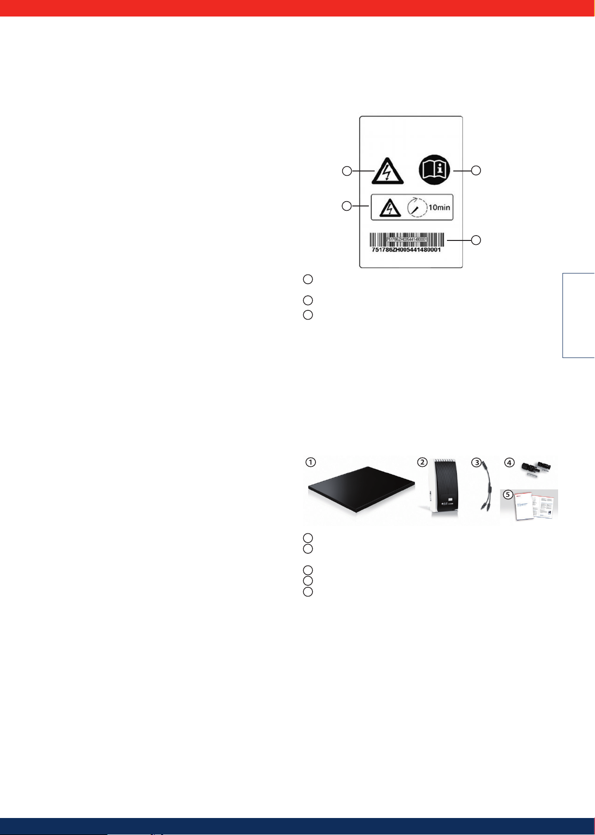
1. Allgemeine Sicherheitshinweise
Bitte treffen Sie alle erforderlichen Vorkehrungen, um jegliche Unfälle zu vermeiden. Die PowerSets dürfen nicht für Systeme genutzt werden, von deren Zuverlässigkeit das Leben oder die körperliche Unversehrtheit von Menschen abhängt,
insbesondere Sicherheitseinrichtungen für die Luftfahrt, medizinische Ausrüstung,
Systeme zur Regelung des Verkehrs oder Ähnliches.
Benutzen Sie die PowerSets ausschließlich für ihren vorgesehenen Zweck. Solar
Frontier empfiehlt ausdrücklich, die folgenden Hinweise zu beachten, um Sachschäden sowie Verletzungen oder im schlimmsten Fall Tod zu verhindern.
Die von Solar Frontier Europe GmbH vertriebenen PowerSets sind nur für
die Installation durch autorisiertes Fachpersonal (siehe 4.2) bestimmt. Wenn
erkennbar ist, dass ein gefahrloser Betrieb nicht mehr möglich ist (z.B. bei
sichtbaren Beschädigungen), das PowerSet sofort vom Netz trennen.
1.1 Sicherheitshinweise Photovoltaik-Modul Solar
Frontier SF170-S
• Nur lizensiertes und geschultes Personal darf die Installation, Verkabelung und
Wartung der SF Module durchführen.
• Alle Hinweise und Warnungen über die SF Module sowie alle Hinweise der
Hersteller von Systemkomponenten sollten vor der Installation und vor dem
Betrieb genau durchgelesen und verstanden werden.
• Um die Gefahr eines elektrischen Schlages zu verringern, ist die Vorderseite der
SF Module während der Installation mit einem lichtundurchlässigen Material
abzudecken.
• SF Module erzeugen reinen Gleichstrom (DC).
• SF Module können keine elektrische Energie speichern.
• Die Serienschaltung von SF Modulen produziert eine höhere Spannung und
die Parallelschaltung einen höheren Strom.
• Verwenden Sie immer SF Module mit gleichartigen elektrischen Werten in
Serien- bzw. Parallelschaltung, um System-Ungleichgewichte oder Beschädigungen von Modulen zu vermeiden.
• Die Leerlaufspannung eines PV-Arrays darf unter keinen Umstanden, z.B. bei niedri-
ger Temperatur, die maximale Systemspannung überschreiten
• Zu hohe Leckströme können Stromschläge oder Brandgefahr verursachen.
• Lösen Sie unter keinen Umständen die Anschlusskabel von sich in Betrieb
befindlichen Modulen. Dies kann zur Bildung von Lichtbögen führen, die zu
schweren Verletzungen bis hin zum Tod führen können.
• Verwenden Sie die SF Module ausschließlich für die Stromerzeugung in terres-
trischen Anwendungen, um elektrische Schocks, Feuer oder andere Unfälle zu
vermeiden.
• Fokussieren Sie Sonnenlicht nicht künstlich mit Hilfe von Linsen oder Spiegeln
auf die Module.
• Verwenden Sie keine andere Strahlungsquelle außer natürlichem Sonnenlicht oder
Umgebungsbeleuchtung für die Stromerzeugung.
• Verwenden Sie SF Module nicht in nassen Umgebungen. Der Kontakt mit Wasser
oder Flüssigkeit erhöht maßgeblich das Risiko von Stromschlägen.
• Aus Sicherheitsgründen dürfen Fehlerströme die Obergrenze nicht überschrei-
ten, welche von den örtlichen Behörden vorgegeben ist.
• Überprüfen Sie die Polarität der Anschlüsse vor der Installation sorgfältig. Fal-
sche Verkabelung kann die SF Module oder die Verbraucher beschädigen.
• Benutzen Sie ausschließlich Werkzeug, Stecker, Kabel und Montagehalter,
welche für elektrische Solarsysteme geeignet sind.
• Während Arbeiten an SF Modulen ausgeführt werden, ist besonders bei DC-
Spannungen höher als 30 V geeignete Schutzkleidung zu tragen. Außerdem
sind alle notwendigen Sicherheitsmaßnahmen zu treffen, um Stromschläge zu
vermeiden.
1.2 Sicherheitshinweise Turbo Wechselrichter
• Installieren und benutzen Sie das Gerät erst, nachdem Sie dieses Dokument
gelesen und verstanden haben.
• Führen Sie die in diesem Dokument beschriebenen Maßnahmen immer in der
angegebenen Reihenfolge durch.
• Bewahren Sie dieses Dokument während der Lebensdauer des Geräts auf. Geben Sie
das Dokument an nachfolgende Besitzer und Benutzer weiter.
• Durch unsachgemäße Bedienung kann der Ertrag des Photovoltaik-Systems
gemindert werden.
• Mit beschädigtem Gehäuse darf das Gerät nicht an die DC- oder AC-Leitungen
angeschlossen sein.
• Gerät sofort außer Betrieb setzen und vom Netz und den Solarmodulen trennen,
wenn eine der folgenden Komponenten beschädigt ist:
- Gerät (keine Funktion, sichtbare Beschädigung, Rauchentwicklung,
eingedrungene Flüssigkeit, etc.)
- Leitungen
- Solarmodule
• Das System darf nicht wieder eingeschaltet werden, bevor
- das Gerät vom Händler oder Hersteller repariert wurde.
- beschädigte Kabel oder Solarmodule von einer Fachkraft repariert wurden.
• Gerät niemals abdecken.
• Gehäuse nicht öffnen: Lebensgefahr! Garantieanspruch verfällt!
.
• Vom Werk angebrachte Schilder und Kennzeichnungen niemals verändern,
entfernen oder unkenntlich machen.
• Anleitung des jeweiligen Herstellers beachten, wenn Sie eine externe Kompo-
nente anschließen, die nicht in diesem Dokument beschrieben ist (z. B. externer
Datenlogger). Falsch angeschlossene Komponenten können den Wechselrichter beschädigen.
Sicherheitshinweise auf dem Gerät:
1
1
1
Gefährliche Spannungen können an den Bauteilen bis zu 10 Min. nach Ab-
schalten von DC-Lasttrennschalter und Leitungsschutz schalter anliegen.
Anleitung beachten!
2
3
Seriennummer als Barcode und in Klarschrift
2
3
Abbildung 1
2. Bestimmungsgemäße Verwendung
Das PowerSet darf nur in netzgekoppelten Photovoltaik-Systemen verwendet
werden. Wechselrichter, Photovoltaik-Module, Kabel, Stecker und Buchsen sind auf
einander abgestimmt. Die Anschlüsse dürfen nicht geerdet werden.
3. Lieferumfang und Aufbau der PowerSets
Jedes Solar Frontier PowerSet setzt sich aus den folgenden Einzelkomponenten
zusammen. Die Anzahl der jeweiligen Komponenten können Sie der unten angefügten Liste an Hand des Typennamens Ihres PowerSets entnehmen.
1
Photovoltaik Modul Solar Frontier SF170-S
2
Solar Frontier Turbo 1P Mini / 1P / 3P1 / 3P2 Wechselrichter (inkl. Wechselrich-
ter, Montageplatte, 1 Paar SunClix Steckverbinder und AC-Stecker)
3
Y-Kabel, Ausführung für (+) und (-)
4
DC-Stecker und DC-Buchsen (jeweils 3 Stück in einer Verpackungseinheit)
5
Installations- und Wartungshandbuch
DEUTSCH
28

Fläche
15,6 m² PowerSet Mini 2.0-170-1p 2.04 kWp 12 x SF170-S 1 x Turbo 1P Mini 1ph 3 (+) & 3 (-) 3 + 3 3
18,2 m² PowerSet Turbo 2.4-170-1p 2,38 kWp 14 x SF170-S 1 x Turbo 1P 1ph 1 (+) & 1 (-) 3 + 3 7
23,4 m² PowerSet Turbo 3.1-170-1p 3,06 kWp 18 x SF170-S 1 x Turbo 1P 1ph 2 (+) & 2 (-) 3 + 3 6
23,4 m² PowerSet Turbo 3.1-170-3p 3,06 kWp 18 x SF170-S 1 x Turbo 3P1 3ph 2 (+) & 2 (-) 3 + 3 6
26,0 m² PowerSet Turbo3.4-170-1p 3,40 kWp 20 x SF170-S 1 x Turbo 1P 1ph 3 (+) & 3 (-) 3 + 3 5
27,3 m² PowerSet Turbo 3.6-170-1p 3,57 kWp 21 x SF170-S 1 x Turbo 1P 1ph 2 (+) & 2 (-) 3 + 3 7
31,2 m² PowerSet Turbo 4.1-170-1p 4,08 kWp 24 x SF170-S 1 x Turbo 1P 1ph 3 (+) & 3 (-) 3 + 3 6
31,2 m² PowerSet Turbo 4.1-170-3p 4,08 kWp 24 x SF170-S 1 x Turbo 3P1 3ph 3 (+) & 3 (-) 3 + 3 6
36,4 m² PowerSet Turbo 4.8-170-1p 4,76 kWp 28 x SF170-S 1 x Turbo 1P 1ph 3 (+) & 3 (-) 3 + 3 7
39,0 m² PowerSet Turbo 5.1-170-3p 5,10 kWp 30 x SF170-S 1 x Turbo 3P2 3ph 4 (+) & 4 (-) 6 + 6 6
45,5 m² PowerSet Turbo 6.0-170-3p 5,95 kWp 35 x SF170-S 1 x Turbo 3P2 3ph 4 (+) & 4 (-) 6 + 6 7
54,6 m² PowerSet Turbo 7.1-170-3p 7,14 kWp 42 x SF170-S 1 x Turbo 3P2 3ph 5 (+) & 5 (-) 6 + 6 7
62,4 m² PowerSet Turbo 8.2-170-1p 8,16 kWp 48 x SF170-S 2 x Turbo 1P 1ph 6 (+) & 6 (-) 6 + 6 6
Auf die PowerSets abgestimmtes Zubehör ist separat bei Solar Frontier erhältlich: DC Kabel, Montagegestell und Befestigungsmaterial, Werkzeug zur Montage und zur
Konfektionierung der Kabel...
PowerSet
Bezeichnung Leistung Module
Wechselrichter Netzanschluss Y-Kabel
Stecker &
Buchse
Module
in Serie
Schematischer Aufbau am Beispiel eines
PowerSet Turbo 3.1
PV Generator
Y-Kabel
DC-Kabel mit Stecker und Buchse
Wechselrichter
Abbildung 2
4.3 Kennzeichnung
4. 3.1 Symbole
Symbol
Vor Gebrauch des Produkts Anleitung lesen. Gerät
4.3.2 Signalwörter
In Verbindung mit den oben beschriebenen Symbolen verwendete Signalwörter:
Signalwort
Gefahr Unmittelbare Gefahr von Tod oder schwerer Körperverletzung
Warnung Mögliche Gefahr von Tod oder schwerer Körperverletzung
Vorsicht
Achtung Möglicher Sachschaden
Hinweis Hinweis zur Bedienung oder zur Benutzung der Anleitung
Beschreibung
Mögliche Gefahr von leichter oder mittelschwerer Körperverletzung
4.3.3 Kennzeichnung im Text
Beschreibung Ort
allgemeiner Gefahrenhinweis Anleitung
Gefahr durch Elektrizität
Anleitung / Gerät
4. Zu dieser Anleitung
4.1 Inhalt
Diese Anleitung enthält alle Informationen, die eine Fachkraft zum Einrichten und
zum Betreiben des PowerSets benötigt.
Beachten Sie bei der Montage weiterer Komponenten (z. B. AC-Kabel, Montagesystem) die Anleitungen der jeweiligen Hersteller.
4.2 Zielgruppe
Zielgruppe dieser Anleitung sind Fachkräfte und Installateure, soweit nicht anders
gekennzeichnet.
Mit Fachkräften sind hier Personen bezeichnet, welche unter anderem:
• über die Kenntnis einschlägiger Begriffe und Fertigkeiten beim Einrichten und
Betreiben von Photovoltaik-Systemen verfügen.
• aufgrund ihrer fachlichen Ausbildung, Kenntnisse und Erfahrungen sowie Kennt-
nis der einschlägigen Bestimmungen die folgenden Arbeiten beurteilen und
mögliche Gefahren erkennen können:
- Montieren von Elektrogeräten
- Konfektionieren und Anschließen von Datenleitungen
- Konfektionieren und Anschließen von Stromversorgungsleitungen
Kennzeichnung Beschreibung
√ Voraussetzung für eine Handlung
1., 2., 3., ...
kursiv Hervorhebung, leicht
fett Hervorhebung, stark
Courier
einzelner Handlungsschritt
mehrere Handlungsschritte in Folge
Bezeichnung von Produktelementen wie Tasten, Anzeigen, Betriebszuständen
29

4.3.4 Abkürzungen
Abkürzung Beschreibung
A
AC
DC Gleichspannung
Derating Leistungsreduzierung
DHCP
ENS
FE Fehlerstrom
l Stromstärke
l
k
I
mpp
kVA Kilovoltampere
kW Kilowatt
kWh Kilowattstunde(n)
m Meter
2
m
MPP
MPP-Tra
Nm Newtonmeter
P elektrische Leistung
Pa Pascal
PV Photovoltaik
SELV, TBTS,
MBTS
SF Solar Frontier
STC Standard Test Conditions
U Spannung
U
L
U
mpp
U
PV
V Volt
2
W/m
η Wirkungsgrad
Stromstärke in Ampere
Wechselspannung
Durch DHCP wird das Gerät automatisch in ein bestehendes
Netzwerk eingebunden (engl.: Dynamic Host Configuration
Protocol)
interne Netzüberwachung des Wechselrichters (deutsch: Einrichtung zur Netzüberwachung mit zugeordneten Schaltorganen).
Kurzschlussstrom
Strom im Maximum Power Point
Quadratmeter
Arbeitspunkt mit der höchsten Leistungsabgabe (engl.: maximum
power point)
cker
regelt die Leistung der angeschlossenen Modulstränge auf den MPP
Schutzkleinspannung (EN: Safety Extra Low Voltage; FR: Très Basse
Tension de Sécurité; ES: Muy Baja Tensión de Seguridad)
Leerlaufspannung
Spannung im Maximum Power Point
am DC-Anschluss anliegende Spannung des Generators
(Photovoltaik-Spannung)
Watt pro Quadratmeter
5. Installation
Für eine sichere Montage sind alle relevanten nationalen und lokalen
Gesetze, Vorschriften und Richtlinien, insbesondere zur Unfallverhütung,
sowie alle relevanten technischen Normen zu beachten.
5.1 Montagesystem / Unterkonstruktion
Die PowerSets werden standardmäßig ohne Montagesystem geliefert. Solar
Frontier bietet ein geeignetes Montagesystem als separat erhältliches Zubehör.
Weitere Informationen hierzu finden Sie unter www.solar-frontier.eu. Generell sind
alle handelsüblichen Montagesysteme geeignet, die eine zulässige Montage nach
den Vorgaben unter Punkt 5.2.3 gewährleisten. Ihr Installateur wird eine geeignete
Lösung vorschlagen können.
5.2 Mechanische Installation Photovoltaik-Modul
Solar Frontier SF170-S
5. 2.1 Standortaufnahme
• Stellen Sie sicher, dass unter den lokalen Bedingungen die maximalen Schnee-
und Windlasten die spezifischen Lastgrenzen der SF Module nicht überschreiten.
• Installieren Sie die SF Module nicht an Standorten, wo sie Öldampf, bzw. korro-
siven Gasen ausgesetzt sind.
• Verschmutzungen der Module durch Sand, Staub o.Ä. sind zu vermeiden, da
dadurch die Energieausbeute herabgesetzt werden kann.
• Setzen Sie SF Module keinen schwefelhaltigen Atmosphären aus.
• Installieren Sie SF Module nicht an Stellen, wo entzündliche Gase strömen oder
sich ansammeln können, da es zu Funkenbildung kommen könnte.
• Installieren Sie SF Module nicht in der Nähe von Feuer.
• Vermeiden Sie die Installation der SF Module an kontinuierlich verschatteten Standor-
ten, da ihre Leistung sonst beeinträchtigt werden kann.
• Installieren Sie SF Module nicht an Standorten mit Temperaturen außerhalb
des in den Produktspezifikationen erwähnten, zulässigen Temperaturbereichs.
5.2.2 Bedienungshinweise
• Zerlegen Sie die SF Module nicht und bauen Sie sie nicht um, da hierdurch
Stromschläge, Brand oder andere Unfälle verursacht werden können. Solar
Frontier haftet nicht für Verluste oder Schäden, welche durch unzulässiges
Zerlegen, Modifizieren oder Missbrauch der Module entstehen.
• Bohren Sie keine zusätzlichen Löcher in den Aluminium-Rahmen. Nur die
vorhandenen Bohrungen dürfen verwendet werden.
• Vermeiden Sie mechanische Spannung an den Modulen, Kabeln oder An-
schlussdosen.
(Für die Modulkabel wird ein Krümmungsradius von mindestens 39 mm
empfohlen)
• Stellen Sie sich nicht oder treten Sie nicht auf die SF Module. Sie könnten sich
dabei verletzen und das Modul beschädigen.
• Lassen Sie SF Module nicht herunterfallen. Verhindern Sie ebenfalls den Sturz
von anderen Gegenstanden darauf. Beide Seiten des Moduls (Front- und Rückabdeckung) sind zerbrechlich.
• Tragen Sie das Modul nicht an der Anschlussdose oder den Kabeln. Anschluss-
dose und Anschlusskabel können dabei beschädigt werden und Folgeschäden
sowie Gefahren verursachen.
• Zerkratzen Sie nicht die Rückabdeckung und die Kabel der SF Module. Reibung
oder Kratzer können Stromschläge, Leckströme oder Unfälle verursachen.
• Zerkratzen Sie die isolierende Beschichtung des Rahmens nicht (ausgenom-
men an der Stelle für die Erdungsverbindung), um die Stabilität des Rahmens
nicht zu beeinträchtigen und keine Korrosion zu verursachen.
• Halten Sie die Wasserdrainagelöcher frei, um mechanische Spannungen durch
Frost zu vermeiden.
• Verschließen Sie die Anschlussdose nicht mit Klebstoff. Verwenden Sie eben-
falls kein Dichtungsmittel, wenn Sie den Deckel der Anschlussdose aufsetzen.
5.2.3 Hinweise für die Montage
Sicherheitshinweise für Montagehalter
• Achten Sie bei der Wahl des Materials vom Montagehalter auf die elektrochemische Spannungsreihe, um galvanische Korrosionen zu vermeiden.
• Ziehen Sie die Befestigungsschrauben fest. Bei lockerer Montage könnten PVModule herunterfallen und Unfälle verursachen.
• Stellen Sie sicher, dass SF Module sicher mit der Unterkonstruktion verbunden
worden sind. Die Unterkonstruktion sollte aus haltbarem, nicht rostendem und
UV beständigem Material bestehen. Bitte beachten Sie die national geltenden
Vorschriften.
• Stellen Sie sicher, dass die Kombination aus Modulen und Unterkonstruktion
entsprechend der lokal definierten Wind- und Schneelasten ausgelegt sind.
Solar Frontier übernimmt keine Verantwortung für Modulschäden, die durch
mangelnde Stabilität der Unterkonstruktion hervorgerufen werden. Bitte
setzen Sie sich für eine entsprechende Unterkonstruktion mit dem Hersteller in
Verbindung.
Allgemeine Hinweise über PV-Module
• Für eine maximale Stromerzeugung ist die typische Ausrichtung von PVModulen nach Süden in der Nordhemisphäre und nach Norden in der Südhemisphäre zu empfehlen.
• Die Module können sowohl im Querformat (waagerecht) als auch im Hochformat (senkrecht) installiert werden.
• Achten Sie auf einen Abstand von 100 mm zwischen den SF Modulen und
dem Dach, um die Belüftung und Kühlung der Module zu ermöglichen und
kondensierte Feuchtigkeit abzuführen.
Montage mit Klemmen
Es sollten mindestens vier korrosionsbeständige Klemmen verwendet werden,
um die SF Module sicher an die Montagehalter zu befestigen. Klemmen sollten
durch mindestens 20 mm lange M8-Edelstahlschrauben an den gekennzeichneten Klemmbereichen (256 mm +/- 75 mm von den Ecken der Modullängsseite
entfernt) der langen Rahmenseite gesichert werden.
Alle Klemmen müssen mindestens 30 mm lang und 3 mm dick sein und sich mit
dem Modulrahmen an mindestens 8 mm über lappen.
Klemmen dürfen das Vorderglas nicht abschatten oder den Modulrahmen verbiegen. Für weitere Hinweise wenden Sie sich bitte an den Hersteller der Klemmen.
Maximale Last: 2.400 Pa auf der Front- und Rückseite des Moduls
DEUTSCH
30

Modul senkrecht zu den Montageschienen
Qu
75 mm
)
Mittelklemme
Endklemme
75 m
75 mm
75 mm 75 mm 75 mm 75 mm
75 mm 75 mm
256 mm 745 mm
Querformat (waagerecht) Hochformat (senkrecht)
Querschnitt eines Arrays
Modul parallel zu den Montageschienen
75 mm
75 mm 75 mm 75 mm
75 mm
75 mm
75 mm
75 mm
75 mm 75 mm
Modul
3 mm
8 mm
Modul
Überlappung zwischen Modul
und Klammer min 8 mm
Schraube
Mutter
Montage-
schiene
Endklemme Mittelklemme
Modul
8 mm
3 mm
ModulModul
75 mm
75mm
745mm
75 mm
75 mm
256mm
Abbildung 3
Abbildung 4
Querschnitt eines Arrays
75 mm 75 mm
256 mm
745 mm
Querformat (waagerecht) Hochformat (senkrecht)
Modul
75 mm
75 mm
75 mm 75 mm
75 mm 75 mm
3 mm
8 mm
Modul
Überlappung zwischen Modul
und Klammer min 8 mm
Mutter
10 mm
Schraube
Montage-
schiene
Überlappung zwischen Modul
und Schiene mindestens 10 mm
Bei abweichenden Montagemethoden setzen Sie sich bitte mit Solar Frontier in Verbindung.
Modul
8 mm
3 mm
Modul Modul
10 mm
Mutter
75 mm 75 mm
745 mm
75 mm 75 mm
256 mm
Abbildung 5
Abbildung 6
31

5.3 Elektrische Installation Photovoltaik Generator
5. 3.1 Elektrische Sicherheitshinweise
• Die Summe der Leerlaufspannungen der Module in Reihenschaltung darf die maximale Systemspannung unter keinen Umständen überschreiten. Ein Rückstrom
durch die Module darf 7 A nicht überschreiten
• Berühren Sie nicht das PV-Modul, die Anschlussdose oder die Kabel mit bloßen
Händen.
• Führen Sie keine Installationsarbeiten durch, wenn die PV-Module, das Werkzeug oder der Installationsort nass sind.
• Die Verbindung zwischen PV-Modul und den angeschlossenen Geräten sollte
isoliert und wasserdicht sein. Bei fehlender Isolierung und Wasserdichtung
können Stromschläge, Leckströme oder Unfälle entstehen.
• Halten Sie die Kabledose und die Verbindungskabel trocken, bis die Anschlüsse
hergestellt sind. Andernfalls besteht die Gefahr einer fehlerhaften Verschaltung.
• Die Verbindungskomponenten zwischen den Modulen müssen kompatibel
mit dem Anschlusssystem sein. Sie müssen für einen einwandfreien Betrieb
und eine lückenlose Sicherheit sorgen.
• Wechselrichter müssen den technischen Anforderungen der Module entsprechen.
• Schließen Sie die PV-Module nicht direkt an Verbrauchern wie Motoren an.
Schwankungen in der Ausgangsleistung können den Motor beschädigen.
• Achten Sie auf die Sicherheitshinweise von Batterien und verstehen Sie sie.
Ein fehlerhafter Einsatz kann schwere Verletzungen wegen hohen Strömen
verursachen.
• Alle Kabel sollten vor einer Beschädigung durch Tiere geschützt werden.
5.3.2 Kabelkonfektionierung
Solar Frontier legt großen Wert darauf, möglichst viele Komponenten vorgefertigt
mitzuliefern, um mögliche Fehlerquellen zu minimieren.
Da jedes Dach und jede PV-Installation ihre Besonderheiten aufweisen, ist es
nötig bestimmte Kabel vor Ort an die Anlage anzupassen und entsprechend zu
konfektionieren. So müssen z.B. die Kabel zur Verlängerung der Verbindungskabel
hin zum Wechselrichter vor Ort konfektioniert werden. Des Weiteren kann es nötig
sein bei unterbrochenen Strängen auf dem Dach (durch z.B. Dachgauben) die
erhöhte Entfernung mittels Erweiterungskabel zu überbrücken. Hierfür dienen das
mitgelieferte DC-Kabel, die Stecker und Buchsen. Darüber hinaus ist die Hosiden
Krimpzange (HSC2009-530030) zum Krimpen der Kontakte erforderlich, welches
nicht im Lieferumfang enthalten ist. Vorkonfektionierte Verbindungskabel dürfen
nicht verändert werden.
Bitte achten Sie auf eine saubere und ordnungsgemäße Konfektionierung
der Kabel um mögliche Fehlerquellen auszuschließen und um eine sichere
Verkabelung zu gewährleisten.
Die eingesetzten DC-Kabel müssen die im Abschnitt 10.5.2 definierten Anforderungen erfüllen und mit den von Solar Frontier gelieferten Steckverbindern
kompatibel sein. Solar Frontier empfiehlt den Einsatz der im Abschnitt 10.5.2
definierten DC-Kabel. Diese sind bei Solar Frontier erhältlich.
Für die Konfektionierung der Kabel ist folgendes Werkzeug erforderlich:
- Montageschlüssel (nicht im Lieferumfang enthalten)
- Krimpzange für gedrehte Kontakte (nicht im Lieferumfang enthalten)
- Abisolierzange (nicht im Lieferumfang enthalten)
Kürzen und Abisolieren des DC-Kabels
Zuerst müssen Sie das Kabel auf die benötigte Länge kürzen. Anschließend wird
mit einer geeigneten Abisolierzange die äußere Kabelisolierung auf einer Länge
von 6,5 bis 7,5 mm entfernt.
Bitte achten Sie hierbei darauf, die Litzen des DC-Kabels nicht zu beschädigen. Eine dadurch hervorgerufene Querschnittverringerung kann zu
elektrischen Fehlern führen.
Abbildung 7
Positionierhilfe
Abbildung 8
.
Stellen Sie das Werkzeug ein:
1. Heben Sie die Positionierhilfe
an
2. Drehen Sie die Positionierhilfe
um ±120° in die gewünschte
Position
Crimpen der gedrehten Kontakte.
Abbildung 9
Crimpzange
Abbildung 10
Abbildung 11
Abbildung 12
Abbildung 13
Abbildung 14
Stecker
Buchse
Kontakt
Pin
Abbildung 15
Zum Crimpen des Pins wird die Positionierhilfe HSC2010 verwendet.
Zum Crimpen des Kontakts wird die
Positionierhilfe HSC2013 verwendet.
Legen Sie den Kontakt oder Pin in
den Platz für den erforderlichen
Querschnitt.
Platzieren sie die Krimp-Hülse
vollständig im Werkzeug wie in
Abbildung 11 ersichtlich.
DEUTSCH
Schließen Sie die Crimp-Zange
zuerst nicht vollständig.
Schließen sie das Werkzeug leicht
und prüfen Sie ob die Crimphülse
sicher im Presseinsatz sitzt.
Führen Sie das abisolierte Ende des
Kabels vollständig in die Crimphülse ein.
Schließen sie das Werkzeug unter
Halten des Kabels nun vollständig
bis die Sperrvorrichtung auslöst.
Prüfen Sie das Crimpergebnis und
den korrekten Sitz aller Kabellitzen.
Führen Sie den gecrimpten Kontakt
in den Stecker bis er spürbar einrastet und verriegelt.
Ziehen Sie leicht am Kabel um zu
prüfen ob der Kontakt fest sitzt und
verriegelt hat.
Achten Sie darauf, dass der Pin
nicht in den Stecker eingeführt
werden darf.
Führen Sie den gecrimpten Pin in
die Buchse bis er spürbar einrastet
und verriegelt.
Ziehen Sie leicht am Kabel um zu
prüfen ob der Pin fest sitzt und
verriegelt hat.
Achten Sie darauf, dass der
Kontakt nicht in die Buchse
eingeführt werden darf.
32

gut
nicht gut
5.3.3 Erdung
Ziehen Sie nun die Verschlusskappen mit einem Anzugsmoment von
1,7 Nm an.
Prüfen Sie, dass es keine Lücke
zwischen Verschlusskappe und
Stecker bzw. Buchse gibt.
Abbildung 16
Hinweise bei der Erdung
Abbildung 17
• Machen Sie sich vor der Installation mit den Erdungsanforderungen vertraut. Lassen
Sie sich von den örtlichen Behörden beraten.
• Wenn notwendig, installieren Sie Fangeinrichtungen oder sonstige Blitzschutzmaß-
nahmen.
• Modulrahmen, Montagehalter, Anschlussdosen und Kabelkanäle sollten für einen
ausreichenden Blitzschutz gemäß den lokalen, regionalen und nationalen Bestimmungen und Richtlinien geerdet werden.
• Eine 4 mm Bohrung im Aluminium-Rahmen des SF Moduls ist für die Erdverbin-
dung vorhanden. Das Erdungskabel ist mit einer Schraube und Unterlegscheibe
am Modulrahmen zu befestigen. Ein elektrischer Kontakt muss vorhanden sein.
Benutzen Sie ein Erdungskabel aus Kupfer mit einem Querschnitt von mindestens
2 mm² (AWG14) sowie einem Temperaturbereich von min. -40 bis 85 °C.
• Alternativ können auch Erdungsklemmen mit integriertem Erdungsdorn, Zahn-
scheiben, Erdungsclips oder -Bügel für PV-Module gemäß NEC Section 250 verwendet werden. Diese Bauteile sind in Übereinstimmung mit den Hersteller-Richtlinien
der Erdungsvorrichtungen zu verwenden. Zur Sicherstellung korrekter Erdung sind
die entsprechenden Firmen zu konsultieren.
Bei abweichenden Erdungsmethoden setzen Sie sich bitte mit Solar Frontier in Verbin-
Erdung (IEC)
Selbstschneidende Schraube
Erdungskabel
Unterlegscheibe
dung.
Verbinden Sie das Erdungskabel an der durch das Erdungszeichen
markierte
Stelle.
Für nähere Informationen bezüglich Empfehlungswerten des Anzugsmomentes wird
auf entsprechende Dokumentation des Schraubenherstellers verwiesen.
Modulrahmen
Kabelschuh
Abbildung 18
5.3.4 Elektrische Verkabelung
• Die SF Module verfügen über ein Anschlusskabel mit einem Anschlussstecker für jeden Pol. Benutzen Sie diese, um das Modul anzuschließen.
• Öffnen Sie nicht die Anschlussdose.
• Zur Zugsentlastung befestigen Sie die Kabel an den Modulrahmen oder dem Montagehalter.
• Herumhängende Kabel sind gefährlich und sollten befestigt werden.
• Kabel müssen vor direkter Sonnenstrahlung geschützt werden, z.B. durch Kabelführung hinter dem Modul.
• Die Summe der Leerlaufspannungen der Module in Serie darf die maximale Systemspannung unter keinen Umständen, auch nicht bei niedrigen Temperaturen,
überschreiten.
• Ein Rückstrom durch das Modul darf auf keinen Fall 7 A überschreiten.
• Der Mindestquerschnitt aller Verbingungskabel beträgt: 2,5 mm².
Serienschaltung
Anschlussdose
Parallelschaltung
Abbildung 19
Bitte achten Sie während Installations- und Verkabelungsarbeiten auf alle relevanten gesundheitlichen, sicherheitstechnischen und ökologischen Richtlinien.
Schematische Darstellung der Standard Modulverkabelung mit Unterbrechung
Sollte es aufgrund von Hindernissen nicht möglich sein, die Module direkt nebeneinander zu montieren, besteht die Möglichkeit, mit denen im Lieferumfang enthaltenen
Stecker- und Buchsenpärchen solche Unterbrechungen zu überbrücken. Eine beispielhafte Vorgehensweise wird in Abbildung 20 veranschaulicht:
Dachfenster
Verlängerungskabel
Abbildung 20
33

5.4 Installation Turbo Wechselrichter
2
3
1
1
5.4.1 Sicherheitsmaßnahmen bei der Installation
Beachten Sie bei den im Abschnitt Installation beschriebenen Maßnahmen die
folgenden Sicherheitshinweise.
Gefahr
Lebensgefahr durch Stromschlag
• Nur Fachkräfte dürfen die im Abschnitt Installation beschriebenen Maßnahmen durchführen.
• Vor Arbeiten am Wechselrichter immer alle DC- und AC-Leitungen wie folgt trennen:
1. AC-Leitungsschutzschalter ausschalten. Vorkehrungen gegen unbeabsichtig-
tes Wiedereinschalten treffen.
2. DC-Lasttrennschalter am Wechselrichter auf Position 0 stellen. Vorkehrungen
gegen unbeabsichtigtes Wiedereinschalten treffen.
3. Hosiden-Verbindungen der DC-Kabel gemäß Anleitung des Herstellers trennen.
Dazu ist ein spezielles Werkzeug erforderlich.
Warnung: DC-Kabel führen Spannung, wenn die Solarmodule beleuchtet sind.
4. AC-Stecker vom Wechselrichter abziehen, wie im Kapitel 5.4.13 beschrieben.
5. Spannungsfreiheit des AC-Steckers allpolig feststellen. Dafür einen geeigneten
Spannungsprüfer verwenden (keinen Phasenprüfstift).
• Kabel am Wechselrichter erst anschließen, wenn Sie in der Anleitung dazu
aufgefordert werden.
• Gehäuse des Wechselrichters nicht öffnen.
• An die RJ45-Buchsen nur SELV-Stromkreise anschließen.
• Kabel so verlegen, dass sich Verbindungen nicht versehentlich lösen können.
• Bei der Leitungsführung darauf achten, dass feuersicherheitstechnische bauli-
che Maßnahmen nicht beeinträchtigt werden.
• Darauf achten, dass keine entzündlichen Gase vorhanden sind.
• Alle geltenden Installationsvorschriften und -normen, nationalen Gesetze sowie An-
schlusswerte des regionalen Stromversorgungsunternehmens einhalten
Achtung
Gefahr der Beschädigung oder Leistungsminderung des Wechselrichters!
• Der Montageort muss folgende Bedingungen erfüllen:
- Die Montagefläche und die nähere Umgebung ist ortsfest, senkrecht, eben,
schwer entflammbar und nicht dauerhaft vibrierend.
- Die zulässigen Umgebungsbedingungen werden eingehalten; siehe 10.2
Technische Daten Wechselrichter.
- Um den Wechselrichter sind folgende Freiräume vorhanden:
ober-/unterhalb: mindestens 200 mm
seitlich/davor: mindestens 60 mm
• Wechselrichter nicht in Ställen mit aktiver Tierhaltung installieren.
• Die auf dem Typenschild angegebenen Anschlusswerte einhalten.
• Die DC-Leitungen dürfen nicht mit Erdpotential verbunden werden (DC-Eingänge und AC-Ausgang sind nicht galvanisch getrennt
Achtung
Beachten Sie beim Übertragen von Daten in ein öffentliches Netzwerk:
• Das Übertragen von Daten in ein öffentliches Netzwerk kann zusätzliche
Kosten verursachen.
• Über ein öffentliches Netzwerk übertragene Daten sind nicht vor dem möglichen Zugriff durch Dritte geschützt.
Hinweis
• Vermeiden Sie die direkte Sonnenbestrahlung des Wechselrichters.
5.4.2 Wechselrichter montieren
Montageplatte befestigen
Montageplatte mit 4 Schrauben an der Montagefläche befestigen:
• Dem Gewicht des Wechselrichters entsprechende Schrauben (und Dübel etc.)
verwenden.
• Die Montageplatte muss eben an der Montagefläche anliegen, die seitlichen
Blechstreifen müssen nach vorne weisen (Abbildung 22).
• Montageplatte vertikal montieren mit Sicherungsblech 1 oben (Abbildung 22).
.
1
Wechselrichter an der Montageplatte anbringen
1
1. Wechselrichter an Griffmulden
die Montageplatte
2. Wechselrichter absenken
einrastet.
1
aufsetzen
oder umlaufendemRand fassen, mittig auf
und leicht andrücken (Abbildung 23).
2
3
, bis das Sicherungsblech der Montageplatte hörbar
Dabei müssen die Haken an der Rückseite des Wechselrichters über die Nasen
an der Montageplatte geführt werden.
3. Der Wechselrichter muss nun fest auf der Montageplatte sitzen und kann nicht
mehr (nach oben) angehoben werden.
Hinweis
Wie Sie den Wechselrichter von der Montageplatte entfernen ist unter 5.4.9
beschrieben.
5.4.3 AC-Anschlüsse vorbereiten
Leitungsschutzschalter
Informationen zum erforderlichen Leitungsschutzschalter und zu den Kabeln
zwischen Wechselrichter und Leitungsschutzschalter finden Sie im Kapitel 10.3.
Fehlerstromschutzschalter
Wenn die örtlichen Installationsvorschriften die Installation eines externen Fehlerstromschutzschalters vorschreiben, dann ist gemäß
IEC 62109-1, § 7.3.8 ein Fehlerstromschutzschalter vom Typ A ausreichend.
Abbildung 23
AC-Stecker konfektionieren
Gefahr
Lebensgefahr durch Stromschlag! Gefahrenhinweise im Abschnitt 5.4.1 beachten!
Netzspannung 220 V ... 240 V
Konfektionieren Sie den mitgelieferten AC-Stecker wie im Anhang unter Kapitel
13.1 beschrieben.
Netzspannung 100 V ... 127 V
Gefahr
Lebensgefahr durch Stromschlag! Netzseitig niemals eine der Phasen L1, L2 oder
L3 mit FE oder N verbinden.
Hinweis
Bei einer Netzspannung von 100 V ... 127 V kann der Wechselrichter zwischen die
Außenleiter L1, L2 und L3 wie folgt angeschlossen werden:
2-phasige Netze
• N und L werden wechselrichterseitig zwischen die Außenleiter L1 – L2 ange-
schlossen. Siehe
• Einer der beiden angeschlossenen Außenleiter wird wechselrichterseitig mit
FE verbunden. Diese Verbindung kann im AC-Stecker oder in einem externen
Unterverteiler vorgenommen werden.
• Abbildung 24 zeigt beispielhaft die wechselrichterseitige Verbindung von L1
und FE:
oben: Verbindung
unten: Verbindung
2
und 3 in Abbildung 24.
1
im AC-Stecker 5
im externen Unterverteiler 6
4
DEUTSCH
3-phasige Netze
• N und L werden wechselrichterseitig zwischen die Außenleiter L1 – L2 oder L1
– L3 oder L2 – L3 angeschlossen.
• Außenleiter wechselrichterseitig mit FE verbinden: wie oben.
• Abbildung 24: wie oben.
Abbildung 22
Die Außenleiterspannungen sind in Abbildung 25 dargestellt.
1. Konfektionieren Sie den mitgelieferten AC-Stecker für die gewählten Außenleiter, wie im Anhang unter Kapitel 13.1 beschrieben. Verschließen Sie den
AC-Stecker noch nicht.
2. Verbinden Sie wechselrichterseitig eine der beiden angeschlossenen Phasen
Abbildung 21
mit FE. Stellen Sie die Verbindung entweder im AC-Stecker oder in einem
externen Unterverteiler her; siehe dazu Abbildung 24.
34

41
Nur für Turbo 1P Mini und Turbo 1P Wechselrichter:
L
2
L
3
L
1
N
100 - 127 V
100 - 127 V
100 - 127 V
L
1
L
2
N
100 - 127 V
100 - 127 V
5.4.7 Modbus RTU Datenverbindungskabel für den An-
schluss eines Energiezählers
Beim Anschluss eines Energiezählers für das Einspeisemanagement kann als
Datenverbindungskabel ein 4-poliges Telefonkabel mit RJ10 Stecker auf der Wechselrichterseite verwendet werden.
Gerät
Anschluss
Kontakt 1 Data A
Wechselrichter
RJ10
2 Data B
3 Ground
4 —
Signal
Abbildung 27
Kontaktbelegung (= Leitungsnummer) des RJ45-Steckers
Abbildung 24
Verbindu ngen von N und FE
im AC-Stecker (ob en)
oder Unterverteiler (unten)
1
Verbindungskabel zwischen N und FE mit Verbindungspunkt im AC-Stecker
2
Außenleiter L1
3
Außenleiter L2
4
Verbindungskabel zwischen N und FE mit Verbindungspunkt im Unterverteiler
5
Gehäuse des AC-Steckers
6
Unterverteiler
Abbildung 25
Außenleiterspannungen
in 2- bis 3-p hasigen Net zen mit
100 V ...127 V
Nur für Turbo 3P1 / 3P2 Wechselrichter:
Konfektionieren Sie den mitgelieferten AC-Stecker wie in nachstehender Abbildung beschrieben.
1
Phase 1
2
Phase 2
3
Phase 3
4
Schutzleiter PE ist im Gerät funktionslos
und muß nicht zwingend angeschlossen
werden da der Wechselrichter
Schutzklasse II ist.
5
Neutralleiter
Abbildung 26
5.4.4 DC-Anschlüsse vorbereiten
Gefahr
Lebensgefahr durch Stromschlag!
Mitgelieferte SunClix Steckverbinder verwenden, damit die spezifische Schutzart
eingehalten wird.
Achtung
Gefahr der Beschädigung des Wechselrichters und der Module.
Die zu den DC-Anschlüssen passenden Gegenstücke polrichtig am DC-Kabel
anschließen.
Hosiden-Gegenstücke gemäß Anleitung unter Kapitel 5.3.2 am DC-Kabel anbringen.
5.4.5 Datenverbindungskabel zur Nutzung von Power
Monitoring vorbereiten
Zur Nutzung des online Monitoring Dienstes Power Monitoring ein RJ45 Standardkabel (Patch.Kabel, Cat5) bereitstellen oder bei Bedarf alternatives Datenverbindungskabel herstellen.
5.4.6 Anschluss eines PowerStorage Systems
Bei dem Einsatz eines PowerStorage Systems können Sie die Inbetriebnahme und
Einrichtung des PowerSets gemäß dieser Anleitung abschließen.
Nehmen Sie anschließend das PowerStorage System wie in der hierfür verfügbaren Anleitung beschrieben in Betrieb. Alle am PowerSet nötigen Einstellungen
werden hierin im Detail beschrieben.
Hinweis
• Materialschäden durch elektrische Spannung! Das alternative Datenverbin-
dungskabel darf nur von einer Fachkraft angefertigt werden.
• Gefahr der Zerstörung des Modbus RTU Eingangs des Wechselrichters. Kontakt
4 der RJ10-Buchse führt Spannung < 20V. Diesen Kontakt nicht benutzen.
5.4.8 Wechselrichter anschließen und AC einschalten
Gefahr
Lebensgefahr durch Stromschlag! Gefahrenhinweise im Abschnitt 5.4.1 beachten.
Achtung
Zwischen den Datenverbindungskabeln (RS 485/Ethernet) und den DC-/AC-Leitungen einen Abstand von 200 mm einhalten, um Störungen bei der Datenübertragung zu vermeiden.
• Bevor Sie das PV-System an das Stromnetz anschließen, stellen Sie sicher, dass
das komplette System den relevanten Bestimmungen entsprechend überprüft,
getestet und genehmigt wurde.
• Je nach lokalen Bestimmungen darf nur zugelassenes Personal das PV-System
ans Stromnetz anschließen und in Betrieb nehmen.
1. Falls erforderlich, Datenverbindung herstellen.
2. Steckverbinder-Gegenstück (DC-Kabel) kräftig in den DC-Anschluss am
Wechselrichter drücken, bis es hörbar einrastet.
3. AC-Stecker auf die Kupplung am Wechselrichter stecken, bis der Stecker
hörbar einrastet.
4. AC-Leitungsschutzschalter einschalten. Die Startseite der ersten Inbetriebnahme wird angezeigt.
5. Erste Inbetriebnahme durchführen und DC einschalten, wie in den Abschnitten 5.4.9 und 5.4.10 beschrieben.
5.4.9 Erste Inbetriebnahme des Wechselrichters
Bedingungen für das Starten der ersten Inbetriebnahme
Die erste Inbetriebnahme startet selbsttätig, wenn zumindest der AC-Anschluss
installiert und eingeschaltet wurde wie zuvor beschrieben. Wenn die erste Inbetriebnahme nicht vollständig durchgeführt wurde, startet sie jedes Mal nach dem
Einschalten.
Geführte erste Inbetriebnahme
Die erste Inbetriebnahme ist eine geführte Bedienung, bei der Folgendes eingestellt wird:
• PowerSet
• Display-Sprache
• Datum/Uhrzeit
• Land
• Blindleistungskennlinie (wenn für das gewählte Land vorgeschrieben)
Einstellen des Landes
Für das Einstellen des Landes gilt:
• Es wird das Land eingestellt, in dem der Wechselrichter installiert ist. Dadurch
lädt der Wechselrichter die vorgegebenen Netzparameter des Landes. Mehr
dazu in der Ländertabelle im Abschnitt 10.4.
• Das Land kann nur einmal eingestellt werden!
• Wenn Sie das falsche Land gewählt haben, wenden Sie sich an Ihren Installa-
teur oder kontaktieren Sie Solar Frontier!
• Wenn Ihr Land am Wechselrichter nicht gewählt werden kann, wenden Sie sich
an Ihren Installateur oder kontaktieren Sie Solar Frontier!
• Das Einstellen des Landes beeinflusst nicht die auf dem Display angezeigte
Sprache. Die Display-Sprache wird separat eingestellt.
35

Bedienung
Erstinbetriebnahme starten
√ Die Checkliste für die Erstinbetriebnahme
wird angezeigt.
• Der Eintrag PowerSet ist markiert.
• Die Kontrollkästchen sind nicht markiert.
Hinweise:
• Wenn ein Punkt der Checkliste aufgerufen
wird, wird sein Kontrollkästchen automatisch
markiert.
• Folgende Punkte werden nur angezeigt, wenn
für das unter dem Punkt Land gewählte
Land eine Blindleistungskennlinie vorgeschrieben ist:
• – Blindleistungskennlinie
(Typ der Blindleistungskennlinie)
– Anzahl Stützstellen
– Stützstelle 1
– Stützstelle 2
– Stützstelle n
– Kennlinie anzeigen
1)
: Wird nur beim Blindleistungskennlinien-Typ
Kennlinie eingeben angezeigt.
2)
: Wird nur angezeigt, wenn unter Anzahl
1)
1)
1) 2)
1)
Stützstellen ein Wert > 2 eingestellt
wurde.
• Die Erstinbetriebnahme wird durch Aufrufen
des Punkts Abschließen abgeschlossen.
• Abschließen kann erst durchgeführt werden,
wenn alle anderen Kontrollkästchen markiert
sind.
1. drücken, um einen Punkt der Checkliste
zu markieren.
2. SET drücken, um den Punkt aufzurufen.
Die Punkte sind nachstehend einz
eln beschrieben.
1. SET drücken. Die erste Zahl der Bezeichnung vom PowerSet blinkt.
2. drücken, um die erste Zahl der Bezeichnung vom PowerSet zu verändern.
3. SET drücken. Die Änderung wird übernommen.
Uhrzeitformat
Uhrzeit
Länderauswahl
Blindleistungskennlinie
1. drücken, um ein Zeitformat zu markieren.
2. SET drücken. Das Zeitformat wird übernommen.
3. ESC drücken. Die Checkliste wird angezeigt.
1. SET drücken. Die Stunde blinkt.
2. drücken, um die Stunde zu ändern.
3. SET drücken. Die Änderung wird übernommen.
4. drücken. Die Minute ist markiert.
5. Schritte 1. bis 3. für die Minute wiederholen.
6. ESC drücken. Die Checkliste wird angezeigt.
Hinweis
Das Land kann nur einmal eingestellt werden!
1. drücken, um ein Land zu markieren.
2. SET drücken.
3. ESC drücken. Der Dialog links erscheint.
4. ESC drücken, um mit Schritt 1. und 2. ein
anderes Land zu wählen oder
SET lange drücken(> 1 s), um das gewählte
Land zu bestätigen. Die Checkliste wird
angezeigt.
1. SET drücken, um den Punkt aufzurufen.
DEUTSCH
Sprache
Datumsformat
Datum
4. drücken. Die zweite Zahl der Bezeichnung vom PowerSet ist markiert.
5. Schritte 1. bis 3. für die zweite Zahl der Bezeichnung vom PowerSet wiederholen.
6. ESC drücken. Die Checkliste wird angezeigt.
1. drücken, um eine Sprache zu markieren.
2. SET drücken. Die Sprache wird übernommen.
3. ESC drücken. Die Checkliste wird angezeigt.
1. drücken, um ein Datumsformat zu
markieren.
2. SET drücken. Das Datumsformat wird
übernommen.
3. ESC drücken. Die Checkliste wird angezeigt.
1. SET drücken. Der Tag blinkt.
2. drücken, um den Tag zu ändern.
3. SET drücken. Die Änderung wird übernommen.
4. drücken. Der Monat ist markiert.
5. Schritte 1. bis 3. für den Monat wiederholen.
6. drücken. Das Jahr ist markiert.
7. Schritte 1. bis 3. für das Jahr wiederholen.
8. ESC drücken. Die Checkliste wird angezeigt.
Anzahl Stützstellen
Stützstelle n
36
2. drücken, um eine Blindleistungskennlinien-Art zu markieren.
3. SET drücken. Der BlindleistungskennlinienTyp wird übernommen.
4. ESC drücken. Die Checkliste wird angezeigt.
Hinweis: Wurde nicht cosPhi = 1 ausgewählt, erscheint ein zusätzlicher Menüpunkt Lade Vorlagen.
1. drücken, um Lade Vorlagen zu markieren.
2. SET drücken.
3. drücken, um eine Standardkennlinie
auszuwählen.
4. SET drücken.
Standardkennlinie wird übernommen.
5. ESC drücken. Die Checkliste wird angezeigt.
1. SET drücken. Der Wert blinkt.
2. drücken, um die Anzahl der Stützstellen
zu ändern.
3. SET drücken. Der Wert wird übernommen.
4. ESC drücken. Die Checkliste wird angezeigt.
1. drücken, um einen Parameter der Stützstelle zu wählen.
Hinweis: P % kann bei der ersten und letzten Stützstelle nicht geändert werden (000 %, 100 %).
2. SET drücken. Der Parameter blinkt.
3. drücken, um den Wert zu ändern.
4. SET drücken. Die Änderung wird übernommen
5. Bei Bedarf Schritte 1. bis 4. für die anderen
Parameter wiederholen.
6. ESC drücken. Die Checkliste wird angezeigt.
.

Kennlinie anzeigen
1. Die zuvor eingestellte Blindleistungskennlinie
wird grafisch angezeigt (Bsp. in Abb. links).
2. ESC drücken. Die Checkliste wird angezeigt.
Hinweis
Die Einstellungen zum Einspeise-Management müssen im Untermenü Energiemanagement gemacht werden.
Abschließen
√ In der Checkliste wurde Abschließen
markiert und SET gedrückt.
Es erscheint einer von 2 Dialogen.
1. Gehen Sie je nach Dialog vor wie folgt
• Dialog Die Einstellungen sind unvollständig:
SET drücken und die offenen Punkte der
Checkliste bearbeiten.
• Dialog Sind alle Einstellungen korrekt?
ESC drücken, um Einstellungen zu korrigieren
oder
SET lange drücken (> 1 s), um die Erstinbetriebnahme abzuschließen.
2. Wurde SET lange gedrückt, startet der
Wechselrichter neu und synchronisiert sich
mit dem Netz (Abb. links).
.
5.4.10 DC einschalten
DC-Lasttrennschalter am Wechselrichter auf Position
I stellen (Abbildung 28). Nach einer Prüfung durch die
interne ENS (ca. 2 Minuten) kann am Display die eingespeiste Leitung angezeigt werden (Sonneneinstrahlung
vorausgesetzt).
Abbildung 28
5.4 .11 Einspeise-Management oder PowerStorage
Weiterhin ist es möglich einen Energiezähler für das Einspeise-Management zu
verwenden. Dieser muss an die Modbus RTU Schnittstelle angeschlossen werden
und folgende Voraussetzungen erfüllen:
Der Wechselrichter kommuniziert über Modbus RTU mit Energiezählern. Dabei gilt:
• Es können nur Energiezähler verwendet werden, die im Wechselrichter vorprogrammiert sind.
• Die vorprgrammierten Zähler sind:
• Herholdt ECS3, Artikelnummer: ECSEM72
• Janitza ECS3, Artikelnummer: ECSEM68MID
• B+G SDM630, Artikelnummer: 1141103
• Carlo Gavazzi EM24, Artikelnummer: EM24-DIN.AV9.3.X.IS.X
• Der Energiezähler muss in positiver Richtung den Bezug aus dem Netz messen.
Beachten Sie dazu die Anleitung des Herstellers.
Alternativ kann unter diesem Menüpunkt auch die Funktion PowerStorage beim
Einsatz eines Solar Frontier Batteriesystems aktiviert werden. Details hierzu entnehmen Sie bitte dem PowerStorage Handbuch.
Modus
1. SET drücken, um den Punkt aufzurufen.
2. drücken, um Energiezähler zu markieren
oder PowerStorage zu aktivieren.
3. SET drücken.
4. ESC drücken, um eine Ebene höher zu
Energiemanagement zu wechseln.
Dynamische Einspeiseregelung
Hinweis
Die ins Netz eingespeiste Leistung wird in
10 W Schritten eingestellt.
Sie kann auf minimal 0 W begrenzt werden.
Konguration Energiezähler
Hinweis
Der Wechselrichter kann nur mit Energiezählern arbeiten, die bereits im Wechselrichter
vorprogrammiert sind. Unter Zählertyp
sind die vorprogrammierten Energiezähler
aufgelistet.
1. SET drücken, um den Punkt aufzurufen.
2. drücken, um einen Zählertyp zu markieren.
3. SET drücken.
4. ESC drücken, um das Untermenü zu
verlassen.
Hinweis:
Die Verbindung zum Energiezähler kann mit
Verbindungstest überprüft werden.
5.4.12 Registrierung und Einrichten des PowerMonitoring
Die Registrierung und das Einrichten des Monitorings kann nach Abschluss der
Inbetriebnahme durchgeführt werden.
Bitte folgen Sie dem Link, welcher auf dem Aufkleber auf der Gehäusevorderseite
zu finden ist. Folgen Sie der geführten Registrierung bis zu deren Abschluss. Weitere Informationen zur Registrierung finden Sie ebenfalls über diesen Link.
5.4.13 Wechselrichter demontieren
Gefahr
Lebensgefahr durch Stromschlag!
Nur Fachkräfte dürfen die im Abschnitt Wechselrichter demontieren beschriebenen Maßnahmen durchführen.
Gefahrenhinweise im Abschnitt 5.4.1 beachten.
AC und DC ausschalten
1. AC-Leitungsschutzschalter ausschalten.
2. DC-Lasttrennschalter am Wechselrichter auf 0 stellen
(Abbildung 29).
Abbildung 29
37

DC-Anschlüsse vom Wechselrichter trennen
3
1
2
4
DC-Kabel gemäß Anleitung des Herstellers trennen. Dazu ist ein spezielles
Werkzeug erforderlich.
Warnung
DC-Kabel führen Spannung, wenn die Solarmodule beleuchtet sind.
AC-Stecker vom Wechselrichter trennen
Für Turbo 1P Mini / 1P Wechselrichter:
1. AC-Stecker von der Kupplung am Wechselrichter lösen wie im Kapitel 13.1
beschrieben.
2. Spannungsfreiheit des AC-Steckers allpolig feststellen. Dafür einen geeigneten
Spannungsprüfer verwenden (keinen Phasenprüfstift).
Für Turbo 3P1 / 3P2 Wechselrichter:
1. AC-Stecker vom Wechselrichter trennen: den Sperrhacken im Vorderbereich
des AC-Steckers mit einem geeigneten Gegenstand zur Entriegelung leicht
eindrücken und Stecker abziehen.
2. Spannungsfreiheit des AC-Steckers allpolig feststellen. Dafür einen geeigneten
Spannungsprüfer verwenden (keinen Phasenprüfstift).
AC-Stecker önen (nur bei Bedarf)
Für Turbo 1P Mini / 1P Wechselrichter:
AC-Stecker öffnen wie im Anhang unter Montage > AC Stecker beschrieben.
Für Turbo 3P1 / 3P2 Wechselrichter:
AC-Stecker öffnen: Zuerst die hintere Kabelverschraubung öffnen und danach
die Sperrhacken links und rechts an Steckergehäuse
(gleichzeitig) durch eindrücken mit geeignetem Werkzeug entriegeln. Dann
Gehäuseoberteil von Kontaktierungsteil abziehen.
6. Aufbau und Funktion Turbo Wechselrichter
6.1 Gehäuse
Abbildung 31
DEUTSCH
Wechselrichter von der Montageplatte entfernen
1. Sicherungsblech der Montageplatte mit einer Hand ca. 5 mm in Richtung
Montagefläche drücken
2. Wechselrichter mit der anderen Hand nur soweit anheben, dass das Siche-
rungsblech nicht mehr einrasten kann
3. Wechselrichter mit beiden Händen anheben, bis die Haken an der Rückseite
des Wechselrichters frei sind
4. Wechselrichter von der Montagefläche entfernen
1
(Abbildung 30).
3
Sicherungsblech loslassen.
2
4
Abbildung 30
1
Haube
Display (monochrom, 128 x 64 Pixel)
2
Typenschild, Seriennummer, Warnhinweise
3
Bedientasten: ESC, , , SET (von links nach rechts)
4
1x AC-Anschluss
5
1x DC-Anschluss Plus (+) für Solarmodule
6
(Phoenix Contact SunClix, berührungssicher)
7
1x DC-Anschluss Minus (−) für Solarmodule
(Phoenix Contact SunClix, berührungssicher)
DC-Lasttrennschalter
8
(trennt Plus- und Minuseingang gleichzeitig)
9
2x RJ45-Buchsen (RS485-Bus)
1x RJ45-Buchse (Ethernet)
10
1x RJ10-Buchse (Modbus RTU)
11
Die Gehäusekomponenten sind nachstehend einzeln beschrieben.
6.3 Bedientasten
Die Bedientasten (4 in Abbildung 31 ) haben folgende Funktionen:
Taste Aktion Funktion allgemein geführte Bedienung
38
ESC
SET
kurz
drücken
lange drücken
(≥ 1 Sekunde)
kurz
drücken
kurz
drücken
kurz
drücken
lange drücken
(≥ 1 Sekunde)
springt eine Menüebene höher
verwirft eine Änderung
springt zur Statusanzeige
• bewegt den Markierungsbalken oder den DisplayInhalt nach oben
• bewegt in einer numerischen Einstellung die Markierung 1 Position nach links
• erhöht einen Einstellwert um 1 Stufe
• bewegt den Markierungsbalken oder den DisplayInhalt nach unten
• bewegt in einer numerischen Einstellung die Markierung 1 Position nach rechts
• verringert einen Einstellwert um 1 Stufe
springt eine Menüebene tiefer
• ein markierter Zahlenwert beginnt zu blinken und
kann geändert werden
• übernimmt eine Änderung
• ändert den Zustand eines Steuerelements (Kontrollkästchen/Optionsfeld)
beantwortet einen Dialog mit Ja
geht 1 Schritt zurück
springt zum Anfang der
geführten Bedienung
–
geht 1 Schritt vor
Tabelle 1

6.4 Übersicht Bedienfunktionen
Für eine bessere Übersichtlichkeit sind nur die Bedientasten und SET eingezeichnet.
Status-
anzeige
Ausgangs-
leistung
aktueller
Tagesertrag *)
PV-
Spannung *)
PV-Strom
*)
Netzspannung
Netzstrom *)
Netz-
frequenz *)
Hauptmenü
SET SET SET
Ertrag
Vergütung *)
Eigen-
verbrauch *)
Autarkiegrad *)
Einstellungen
Selbsttest *)
Generator-
kennlinie
SET
SET SET
SET SET
SET
Tag
Monat
Jahr
Gesamt
Uhrzeit/Datum
Vergütung *)
Energie-
management *)
Messwerte
Max. Werte
zurücksetzen
Ereignisproto-
koll löschen
Untermenüs
Modus *)
Dyn. Einspeise-
regelung *)
RS485-
Adresse *)
Konfiguration
Energiezäh. *)
DHCP
IP-AdresseSprache
aus *)
PowerStorage
*)
Energiezähler *)
Zählertyp *)
Blindleistung
einstellen *)
Innen-
temperatur *)
Leistungs-
reduzierung *)
Tagesmaximal-
leistung *)
Abs. Maximal-
leistung *)
Tagesmaximal-
ertrag *)
Betriebs-
stunden *)
Gesamt-
ertrag *)
Ereignisprotokoll
Information
SET
Kontaktdaten
System-
information
Länder-
einstellung
Blindleistungs-
kennlinie *)
Selbsttest *)
Netzwerk
Kontrast
RS485-
Adresse *)
Netzwerk
Alarm
Hintergrundbeleuchtung
Service
SET
SET
Subnetz-
maske
Gateway
DNS
Web-Portal
Ländereinstlg.
löschen
Spannungs-
grenzen
Frequenz-
grenzen
Spannungs-
grenzen Ø
Leistungs-
begrenzung
Festspannung
Werks-
einstellung
CO
-
2
Einsparung *)
*) Dieser Menüpunkt wird nicht immer angezeigt. Ob er vorhanden ist, hängt von den
Einstellungen am Wechselrichter und der Fimware-Version ab.
Alle Parameter
6.5 Service-Menü
Nachfolgend sind Einträge aus dem Service-Menüs beschrieben. Einige Einträge sind passwortgeschützt.
Das Passwort erhalten Sie vom technischen Support.
Achtung
Risiko von Minderertrag. Im Service-Menü können Wechselrichter- und Netzparameter geändert werden. Das Service-Menü darf nur durch eine Fachkraft bedient werden die sicherstellt, dass die Änderung nicht gegen geltende Vorschriften und Normen verstößt.
39

Service-Menü aufrufen und bearbeiten
1. Menüeintrag Service aufrufen.
2. SET drücken. Die Abb. links erscheint.
3. gleichzeitig 3 s lang drücken. Das
Service-Menü erscheint (Abb. links).
4. drücken, um einen Menüeintrag zu
markieren.
5. SET drücken, um den Menüeintrag zu
bearbeiten.
Dabei gilt:
• Falls erforderlich, Passwort eingeben (Abb. links).
• Innerhalb eines Menüeintrags bei Bedarf
drücken, um weitere Einstellwerte anzuzeigen
und zu ändern (Bsp. Spannungsgrenzen).
Leistungsbegrenzung
Die Ausgangsleistung des Wechselrichters kann
manuell bis minimal 500 W begrenzt werden. Ist die
Leistung manuell begrenzt, wird in der Statusanzeige das Symbol Leistungsreduzierung & der
Messwert Leistungsreduzierung/Grund:
Benutzervorgabe angezeigt.
Ländereinstellung löschen
Nachdem die Ländereinstellung gelöscht wurde,
startet das Gerät neu und zeigt die geführte erste
Inbetriebnahme an.
Werkseinstellungen
Beim Rücksetzen auf die Werkseinstellung werden folgende Daten gelöscht:
• Ertragsdaten
• Ereignismeldungen
• Datum und Uhrzeit
• Ländereinstellung
• Display-Sprache
• Netzwerk-Einstellungen
Nachdem die Werkseinstellung gelöscht wurde,
startet das Gerät neu und zeigt die geführte erste
Inbetriebnahme an.
6.6 Störungsbeseitigung
Störungen werden durch Ereignismeldungen angezeigt wie nachstehend beschrieben. Das Display blinkt rot. Tabelle 2 "Liste der Ereignismeldungen" enthält
Hinweise zum Beseitigen von Störungen.
Aufbau
2
1
5
6
3
Funktion
Typen von Ereignismeldungen
• Typ Information (Symbol )
Der Wechselrichter hat einen Fehler erkannt, der das Einspeisen nicht beeinträchtigt. Ein Eingreifen durch den Benutzer ist nicht erforderlich.
• Typ Warnung (Symbol )
Der Wechselrichter hat einen Fehler erkannt, der Mindererträge nach sich ziehen
kann. Es wird empfohlen, die Fehlerursache zu beseitigen!
• Typ Fehler (Symbol )
Der Wechselrichter hat einen schwerwiegenden Fehler erkannt. Solange der
Fehler besteht, speist der Wechselrichter nicht ein.
Der Installateur muss verständigt werden! Mehr dazu in Tabelle 2 "Liste der
Ereignismeldungen".
Anzeigeverhalten
Neue Ereignismeldungen werden sofort eingeblendet. Die Meldungen verschwinden,
nachdem sie quittiert wurden oder ihre Ursache behoben wurde.
Hinweis
Wird eine Ereignismeldung quittiert dann bestätigt der Bediener, dass er die Meldung registriert hat. Der Fehler, der die Ereignismeldung auslöste, wird dadurch
nicht behoben!
Existieren Meldungen, deren Ursache behoben ist, die aber noch nicht quittiert
wurden, dann wird in der Statusanzeige
Fehler erneut auftritt, wird er erneut angezeigt.
Bedienung
Ereignismeldungen enthalten folgende Informationen:
4
Symbol für den Typ der Ereignismeldung
1
Datum/Uhrzeit, als das Ereignis auftrat
2
3
ACTIVE = Ursache der Ereignismeldung
besteht noch oder
Datum/Uhrzeit, als die Ursache der Ereig-
nismeldung behoben wurde.
Ursache der Ereignismeldung:
4
5
Zähler: Nr. angezeigte Ereignismeldung /
Anzahl aller Ereignismeldungen;
max. Anzahl aller Ereignismeldungen = 30
6
NEW wird angezeigt, solange die Ereignismel-
dung noch nicht mit ESC oder quittiert
wurde.
angezeigt. Wenn ein bereits quittierter
DEUTSCH
Spannungsgrenzen (Spitzenwert)
Folgende Spannungsgrenzen können geändert
werden:
• oberer Abschaltwert Spannung
• unterer Abschaltwert Spannung 1) (Abb. links)
1)
Der Abschaltwert bezieht sich auf den Spitzen-
wert der Spannung.
Frequenzgrenzen
Folgende Frequenzgrenzen können geändert
werden:
• oberer Abschaltwert
• unterer Abschaltwert (Abb. links)
• Einschaltschwelle Leistungsreduzierung (wegen zu hoher Frequenz
• Schwellwert Wiederzuschaltfrequenz
Spannungsgrenzen Ø (Mittelwert)
Folgende Spannungsgrenzen können geändert
werden:
• oberer Abschaltwert1) (Abb. links)
• unterer Abschaltwert
1)
•
wert der Spannung.
1)
1)
Der Abschaltwert bezieht sich auf den Mittel-
Ereignismeldung quittieren
√ Eine Ereignismeldung mit dem Vermerk NEW wird angezeigt.
ESC/ / drücken. Die Ereignismeldung ist quittiert.
Ereignismeldungen anzeigen
1. Im Hauptmenü Ereignisprotokoll wählen.
2. SET drücken. Die Ereignismeldungen werden chronologisch sortiert angezeigt
(neueste zuerst).
3. drücken, um durch die Ereignismeldungen zu blättern.
40

Ereignismeldung Beschreibung Typ
Datenübernahme
fehlgeschlagen
Eine Einstellung z.B. während der Erstinbetriebnahme
ist fehlgeschlagen, da sie nicht korrekt übertragen
wurde.
Führen Sie die Einstellung erneut durch.
Verständigen Sie Ihren Installateur, wenn der Fehler
weiterhin auftritt
Eine
Inselbildung
wurde erkannt
Das Netz führt keine Spannung (Selbstlauf des Wechselrichters). Der Wechselrichter darf aus Sicherheitsgründen nicht ins Netz einspeisen. Er schaltet sich ab,
solange der Fehler besteht (Display dunkel).
Verständigen Sie Ihren Installateur, wenn dieser
Fehler öfter auftritt.
FE nicht
angeschlossen
Die Funktionserde ist nicht angeschlossen. Der
Wechselrichter darf aus Sicherheitsgründen nicht ins
Netz einspeisen.
Verständigen Sie Ihren Installateur.
Fehlerstrom zu
hoch
Der Fehlerstrom, der vom Plus- bzw. Minus-Eingang
über die PV-Generatoren zur Erde fließt, überschreitet
den zulässigen Wert. Der Wechselrichter schaltet sich
aufgrund gesetzlicher Vorgaben automatisch ab,
solange der Fehlerzustand besteht.
Verständigen Sie Ihren Installateur.
Fehlfunktion
Hochsetzsteller
Eine interne Komponente des Wechselrichters ist
defekt. Der Wechselrichter speist nicht oder mit
verminderter Leistung ins Netz ein.
Verständigen Sie Ihren Installateur.
Gerät ist
überhitzt
Trotz Leistungsreduzierung ist die maximal zulässige
Temperatur überschritten. Der Wechselrichter speist
nicht ins Netz, bis der zulässige Temperaturbereich
erreicht ist.
1. Überprüfen Sie, ob die Montage-Bedingungen
erfüllt sind.
2. Verständigen Sie Ihren Installateur, wenn die Meldung öfter auftritt.
Hochsetzsteller
hat falsche HWVersion
Der Wechselrichter kann eine interne Komponente
nicht erkennen oder sie passt nicht zu den anderen
Komponenten. Der Wechselrichter kann nicht ins Netz
einspeisen.
Verständigen Sie Ihren Installateur.
Hochsetzsteller
nicht angeschlossen
Hochsetzsteller
defekt
Die Verbindung der internen Komponenten ist unterbrochen. Der Wechselrichter speist nicht ins Netz ein.
Verständigen Sie Ihren Installateur.
Der Hochsetzsteller ist defekt, der Wechselrichter
speist nicht oder mit verminderter Leistung ins Netz
ein.
Verständigen Sie Ihren Installateur.
Hochsetzsteller
nicht erkannt
Interne Info
Verständigen Sie Ihren Installateur.
Verständigen Sie Ihren Installateur, wenn die Mel-
dung öfter auftritt.
Interne Warnung
Verständigen Sie Ihren Installateur, wenn die Meldung öfter auftritt.
Interner Fehler
Verständigen Sie Ihren Installateur, wenn die Meldung öfter auftritt.
Isolationsfehler
Der Isolationswiderstand zwischen Plus- bzw. MinusEingang und Erde unterschreitet den zulässigen Wert.
Der Wechselrichter darf aus Sicherheitsgründen nicht
ins Netz einspeisen.
Verständigen Sie Ihren Installateur.
Kein Branding
Der Wechselrichter hat falsche oder fehlerhafte Gerätedaten. Er kann deshalb nicht ins Netz einspeisen.
Verständigen Sie Ihren Installateur.
L und N vertauscht
Außen- und Neutralleiter sind vertauscht angeschlossen. Der Wechselrichter darf aus Sicherheitsgründen
nicht ins Netz einspeisen.
Verständigen Sie Ihren Installateur.
Ländereinstellung fehlerhaft
Länderparameter
ungültig
Es besteht eine Inkonsistenz zwischen der gewählten
und der im Speicher hinterlegten Ländereinstellung.
Verständigen Sie Ihren Installateur.
Der Wechselrichter kann nicht ins Netz einspeisen, da
er keine gültigen Parameter hat.
Verständigen Sie Ihren Installateur.
Leistungsreduzierung wegen
Temperatur
Der Wechselrichter reduziert seine Ausgangsleistung, da
die maximal zulässige Temperatur erreicht wurde.
1. Überprüfen Sie, ob die Montage-Bedingungen
erfüllt sind.
2. Verständigen Sie Ihren Installateur, wenn der Fehler
öfter auftritt.
Lesen der Ländereinstellung
fehlerhaft
Der Wechselrichter konnte das eingestellte Land nicht
korrekt aus dem Speicher lesen.
Verständigen Sie Ihren Installateur.
Ereignismeldung Beschreibung Typ
Lüfter defekt
Der interne Lüfter des Wechselrichters ist defekt. Der
Wechselrichter speist möglicherweise mit verminderter Leistung ins Netz ein.
Verständigen Sie Ihren Installateur.
Netzfrequenz zu
hoch für Wiedereinschalten
Der Wechselrichter kann nach dem Abschalten nicht
wieder einspeisen, da die Netzfrequenz den gesetzlich vorgegebenen Einschaltwert überschreitet.
Verständigen Sie Ihren Installateur, wenn der Fehler
öfter auftritt.
Netzfrequenz zu
niedrig für Wiedereinschalten
Der Wechselrichter kann nach dem Abschalten nicht
wieder einspeisen, da die Netzfrequenz den gesetzlich
vorgegebenen Einschaltwert unterschreitet..
Verständigen Sie Ihren Installateur, wenn der Fehler
öfter auftritt.
Netzfrequenz zu
hoch
Die am Wechselrichter anliegende Netzfrequenz
überschreitet den zulässigen Wert. Der Wechselrichter
schaltet sich aufgrund gesetzlicher Vorgaben automatisch ab, solange der Fehlerzustand besteht.
Verständigen Sie Ihren Installateur, wenn der Fehler
öfter auftritt.
Netzfrequenz zu
niedrig
Die am Wechselrichter anliegende Netzfrequenz unterschreitet den zulässigen Wert. Der Wechselrichter schaltet sich aufgrund gesetzlicher Vorgaben automatisch ab,
solange der Fehlerzustand besteht.
Verständigen Sie Ihren Installateur, wenn der Fehler
öfter auftritt.
Netz-Relais
defekt
Der Wechselrichter hat erkannt, dass ein Netz-Relais
defekt ist und speist deshalb nicht ins Netz ein.
Verständigen Sie Ihren Installateur.
Netzspannung zu
niedrig für Wiedereinschalten
Der Wechselrichter kann nach dem Abschalten nicht
wieder einspeisen, da die Netzspannung den gesetzlich
vorgegebenen Einschaltwert unterschreitet..
Verständigen Sie Ihren Installateur, wenn der Fehler
öfter auftritt.
Netzspannung Ø
zu hoch
Die über einen gesetzlich vorgegebenen Zeitraum
gemittelte Ausgangsspannung überschreitet den zulässigen Toleranzbereich. Der Wechselrichter schaltet sich
automatisch ab, solange der Fehlerzustand besteht.
Verständigen Sie Ihren Installateur, wenn der Fehler
öfter auftritt.
Netzspannung Ø
zu niedrig
Die über einen gesetzlich vorgegebenen Zeitraum
gemittelte Ausgangsspannung unterschreitet den zulässigen Toleranzbereich. Der Wechselrichter schaltet sich
automatisch ab, solange der Fehlerzustand besteht.
Verständigen Sie Ihren Installateur, wenn der Fehler
öfter auftritt.
Netzspannung zu
hoch
Die am Wechselrichter anliegende Netzspannung
überschreitet den zulässigen Wert. Der Wechselrichter
schaltet sich aufgrund gesetzlicher Vorgaben automatisch ab, solange der Fehlerzustand besteht.
Verständigen Sie Ihren Installateur, wenn der Fehler
öfter auftritt.
Netzspannung zu
hoch für Wiedereinschalten
Der Wechselrichter kann nach dem Abschalten nicht
wieder einspeisen, da die Netzspannung den gesetzlich
vorgegebenen Einschaltwert überschreitet.
Verständigen Sie Ihren Installateur, wenn der Fehler
öfter auftritt.
Übertemperatur
HSS
Die maximal zulässige Temperatur des Hochsetzstellers
ist überschritten. Der Wechselrichter speist nicht ins
Netz, bis der zulässige Temperaturbereich erreicht ist.
1. Überprüfen Sie, ob die Montage-Bedingungen
erfüllt sind.
2. Verständigen Sie Ihren Installateur, wenn die Meldung öfter auftritt.
Uhrzeit/ Datum
verloren
Der Wechselrichter hat die Uhrzeit verloren, da er zu
lange nicht an das Netz angeschlossen war. Ertragsdaten
können nicht gespeichert werden, Ereignismeldungen
nur mit falschem Datum.
Korrigieren Sie die Uhrzeit unter
Einstellungen Uhrzeit/Datum.
Keine Verbindung
zum Energiezähler
Es besteht zwischen dem Wechselrichter und dem Energiezähler (bzw. PowerStorage System) keine bzw. keine
korrekte Kommunikationsverbindung.
Verständigen Sie Ihren Installateur, um die Verbindung überprüfen zu lassen.
Keine Verbindung
zu PowerStorage
Es besteht zwischen dem Wechselrichter und dem Energiezähler (bzw. PowerStorage System) keine bzw. keine
korrekte Kommunikationsverbindung.
Verständigen Sie Ihren Installateur, um die Verbindung überprüfen zu lassen.
41
Tabelle 2

7. Wartung
9. Entsorgung
7.1 Wartung Photovoltaik-Modul Solar Frontier
SF170 -S
Eine monatliche Sichtprüfung wird ausdrücklich empfohlen, um die Leistung der
SF Module und die Sicherheit des Aufbaus auf dem höchsten Stand zu halten.
• Entfernen Sie Verschmutzungen oder Blätter von der Modulfläche und über-
prüfen Sie sie auf sonstige sichtbare Schäden. Benutzen Sie keine Reinigungsmittel für die Reinigung der SF Module, weil sie die Kantendichtung beschädigen könnten.
• Benutzen sie für die Reinigung keine harten Bürsten. Benutzen Sie ausschließ-
lich weiche Lappen um Verschmutzungen aus den Modulen zu entfernen.
• Wenn Sie Ersatzteile benötigen, stellen Sie sicher, dass Ihr Installateur nur
solche Teile einsetzt, welche durch den Hersteller spezifiziert sind und die gleichen Eigenschaften wie die Originalteile besitzen. Unzulässiger Ersatz könnte
Brand, Stromschläge oder sonstige Gefährdungen verursachen.
• Stellen Sie die Benutzung der SF Module ein, wenn Sie eine Beschädigung
oder ungewöhnliche Phänomene feststellen. Lassen Sie sie unmittelbar durch
einen zugelassenen Techniker überprüfen.
7.2 Wartung DC-System
Das DC-System ist wartungsfrei. Dennoch empfiehlt es sich regelmäßig die Kabel
und Stecker auf Beschädigungen zu kontrollieren.
7.3 Wartung Turbo Wechselrichter
Der Wechselrichter ist praktisch wartungsfrei. Dennoch empfiehlt es sich regelmäßig zu kontrollieren, ob die Kühlrippen an der Vorder- und Rückseite des Geräts
staubfrei sind. Reinigen Sie das Gerät bei Bedarf wie nachstehend beschrieben.
Achtung
Gefahr der Zerstörung von Bauteilen.
• Reinigungsmittel und -geräte an der Vorderseite des Wechselrichters nicht zwi-
schen die Kühlrippen (unter der grauen Haube) gelangen lassen.
Insbesondere folgende Reinigungsmittel nicht verwenden:
- lösungsmittelhaltige Reinigungsmittel
- Desinfektionsmittel
- körnige oder scharfkantige Reinigungsmittel
Staub entfernen
Es wird empfohlen, Staub mit Druckluft (max. 2 bar) zu entfernen.
Gefahr
Lebensgefahr durch Stromschlag! Reinigungsmittel nur mit einem nebelfeuchten
Tuch anwenden.
Stärkere Verschmutzung entfernen
Stärkere Verschmutzungen mit einem nebelfeuchten Tuch entfernen (klares
Wasser verwenden). Bei Bedarf statt Wasser eine 2%ige Kernseifelösung verwenden.
Nach Abschluss der Reinigung Seifenreste mit einem nebelfeuchten Tuch entfernen.
9.1 Entsorgung innerhalb der EU
Dieses Zeichen auf den Modulen und Wechselrichtern zeigt
an, dass diese Produkte am Ende ihrer Lebensdauer nicht
mit dem Hausmüll entsorgt werden dürfen.
Für die Entsorgung und das Recycling bringen Sie die Produkte bitte zu autorisierten Sammelstellen, bei denen sie es
kostenlos abgeben können. In manchen Ländern können
Sie sie alternativ dazu bei Ihrem zuständigen Händler abgeben, bei dem Sie Ersatzware beziehen.
Bitte kontaktieren Sie Ihre zuständige Behörde für weitere
Details zum nächstgelegenen autorisierten Sammelpunkt.
Die DC-Kabel können über entsprechende Sammelstellen als Elektroschrott
entsorgt werden.
Bei Missachtung der Regeln können je nach geltendem Recht Strafen verhängt
werden.
9.2 Entsorgung außerhalb der EU
Das Symbol der durchgestrichenen Mülltonne ist nur in der europäischen Union
(EU) gültig. Wenn sie Ihr Produkt entsorgen möchten kontaktieren Si ebitte Ihre
zuständige Behörde oder Ihren Händler um die korrekte Entsorgungsmethode zu
erfragen.
10. Technische Daten und Datenblätter
10.1 Photovoltaik-Modul Solar Frontier SF170-S
Elektrische Spezikationen
Standardtestbedingungen (STC)*1
Nennleistung Pmax 170 W
Leerlaufspannung Voc 112 V
Kurzschlussstrom Isc 2,20 A
Nennspannung Vmpp 87,5 V
Nennstrom Impp 1,95 A
Nominelle Betriebsbedingungen
für die Zelltemperatur (NOCT)*2
Nennleistung Pmax 126 W
Leerlaufspannung Voc 102 V
Kurzschlussstrom Isc 1,76 A
Nennspannung Vmpp 82,1 V
Nennstrom Impp 1,55 A
DEUTSCH
8. Transport und Lagerung
Achten Sie auf alle Hinweise auf der Verpackung, wenn Sie SF PowerSets lagern
oder transportieren. Für die Lagerung sollte ein trockener Raum gewählt werden.
Die Verpackung ist nicht wasserdicht. Alle elektrischen Bauteile sind bei Transport
und Lagerung von Flüssigkeiten fernzuhalten. Die SF PowerSets müssen bis zur
Installation in der Originalverpackung verbleiben.
Den Modulen können geringe Mengen weißen Pulvers anhaften, die vom Verpackungsmaterial stammen. Dies hat keinen Einfluss auf die Leistung der Module
und kann vernachlässigt werden.
*1 Angaben gemessen unter Standardtestbedingungen "STC" definiert durch die IEC Norm
(1000 W/m² Einstrahlung, 25°C Modultemperatur, AM 1,5 mit Toleranzen von ±10% für Isc
und Voc und +10% / -5% für Pmax). Der Modulwirkungsgrad unter 200 W/m² Einstrahlung
liegt typischerweise bei 98 % (±1.9 %) vom STC-Wirkungsgrad.
*2
Nominelle Temperaturbedingungen der Zelle (NOCT): Temperatur des Moduls während des
Betriebs bei 800 W/m2 Einstrahlung, 20°C Lufttemperatur, 1m/s Windstärke und im Leerlauf.
42

Thermische Kenndaten
A
(444)
±0 5
934
±2
598.5
±5
1200±100
2×Grounding
474.9
±5
88.1
66
47.8
21.5 21.5
120
(538.5)
150
(50)
31
±1
225 372.5
31
±1
225372.5
454.5 454.5
Mounting holes
Mounting holes
Label
8)
(-)
(+)
±2
4)
5 5
±5
9
±5
13.7
φ
φ
φ
φ
φ
φ
NOCT 47 °C
Temperatur-Koezient Isc α +0,01 %/K
Temperatur-Koezient Voc β -0,30 %/K
Temperatur-Koezient Pmax δ -0,31 %/K
Modulzeichnung
(7)
20
1257
±2
B B
Kenndaten für Systemdesign
Maximale Systemspannung Vsys 1.000 V DC
Rückstrombelastbarkeit Ir 7 A
Mechanische Kenndaten
Maße (L x B x H) 1.257 x 977 x 35 mm
Gewicht 20 kg / 16,3 kg/m²
Modul-Betriebstemperatur -40 °C bis 85 °C
Anwendungsklasse
Klasse A
nach IEC 61730
Feuerschutzklasse
Klasse C
nach IEC 61730
Anschlusskabel
2,5 mm2 / AWG14
(Halogen frei)
Maximale Schneelast auf der Vorderseite des Moduls 2.400 Pa
Maximale Windlast auf der Rückseite des Moduls 2.400 Pa
±2
90
977
±5
±5
574.9
565.5
±5
427.1
±0.5
35
449.9
±5
4 × Ø 8.5
2 × Ø 4
(23.8)
4 × Ø 6.6
A
12
35
30
A-A
13 5
35
2 × Ø 4.5
30
B-B
13,5
35
30
12
35
30
Nr. Element Anzahl Beschreibung
1 Zelle 1 CIS auf Glassubstrat
2 Frontabdeckung 1 Thermisch behandeltes, transparentes Glas
3 Laminierung E VA
4 Rückabdeckung Wetterfeste Kunststofffolie
5 Rahmen 1 Set Anodisierte Aluminiumlegierung (schwarz)
6 Kantendichtung Butyl
7 Anschlussdose 1 Mit Bypassdiode
8 Anschlusskabel
2
2,5 mm
/ AWG14 (mit wasserdichtem
Stecker Hosiden HSC - MC4 steckbar)
9 Klebstoff Silikon
10 Aufkleber 1 Produktbeschriftung
11 Schraube 8 Edelstahl (SUS304J3)
12 Barcode-Aufkleber 1 Seriennummer
43

10.2 Technische Daten Turbo Wechselrichter
Turbo 1P Mini Turbo 1P Turbo 3P1 Turbo 3P2
DC-Eingangsseite (PV-Generatoranschluss)
Anzahl DC-Eingänge 1 1 1 1
Maximale Startspannung 420 V 845 V 1000 V 1000 V
Maximale Eingangsspannung 420 V 845 V 1000 V 1000 V
Minimale Eingangsspannung für Einspeisung 75 V 350 V 250 V 250 V
Start-Eingangsspannung 90 V 350 V 250 V 250 V
Nenneingangsspannung 255 V 540 V 510 V 790 V
Minimale Eingangsspannung für Nennleistung 180 V 360 V 375V 575 V
MPP-Spannung 75 V … 350 V 360 V … 700 V 375 V … 700 V 575 V … 700 V
Maximaler Eingangsstrom 11,5 A 12 A 11 A 11 A
Nenneingangsstrom 8 A 8 A 8 A 8 A
Maximale Eingangsleistung bei maximaler
Ausgangswirkleistung
Nenneingangsleistung (cos φ = 1) 2050 W 4310 W 4100 W 6330 W
Leistungsabsenkung / Begrenzung automatisch wenn:
AC-Ausgangsseite (Netzanschluss)
Ausgangsspannung
(abhängig von der Ländereinstellung)
Nennausgangsspannung 230 V 230 V 400 V 400 V
Maximaler Ausgangsstrom 12 A 18,5 A 7 A 10 A
Nennausgangsstrom 8,7 A 18,3 A 3,3 A 5,2 A
Maximale Wirkleistung (cos φ = 1) 2000 W 4200 W 4000 W 6200 W
Maximale Wirkleistung (cos φ = 0,95) 2000 W 3990 W 3800 W 5890 W
Maximale Scheinleistung (cos φ = 0,95) 2100 VA 4200 VA 4000 VA 6200 VA
Maximale Wirkleistung (cos φ = 0,9) - - 3600 W 5580 W
Maximale Scheinleistung (cos φ = 0,9) - - 4000 VA 6200 VA
Nennleistung 2000 W 4200 W 4000 W 6200 W
Nennfrequenz 50 Hz und 60 Hz
Netztyp
Netzfrequenz 45 Hz ... 65 Hz (abhängig von der Ländereinstellung)
Verlustleistung im Nachtbetrieb < 2 W < 1 W < 3 W < 3 W
Einspeisephasen einphasig einphasig dreiphasig dreiphasig
Klirrfaktor (cos φ = 1) < 2 % < 2 % < 1 % < 1 %
Leistungsfaktor cos φ
Charakterisierung des Betriebsverhaltens
Maximaler Wirkungsgrad
Europäischer Wirkungsgrad 97,5 % 98,2 % 98,1 % 98,3 %
Kalifornischer Wirkungsgrad 97,6 % 98,2 % 98,4 % 98,5 %
MPP Wirkungsgrad > 99,7 % (statisch),
Wirkungsgradverlauf (bei 5 %, 10 %, 20 %, 25 %, 30 %,
50 %, 75 %, 100 % der Nennleistung) bei Nennspannung
Wirkungsgradminderung bei Erhöhung der Umgebungstemperatur (bei Temperaturen > 40 °C)
Wirkungsgradänderung bei Abweichung von der
DC-Nennspannung
Eigenverbrauch < 4 W < 4 W < 8 W < 8 W
Leistungsreduzierung bei voller Leistung ab 50 °C (T
Einschaltleistung 10 W
Ausschaltleistung 5 W 5 W 8 W 8 W
Sicherheit
Schutzklasse II
Trennungsprinzip keine galvanische Trennung, trafolos
Netzüberwachung ja, integriert
Isolationsüberwachung ja, integriert
Fehlerstromüberwachung ja, integriert
Ausführung Überspannungsschutz Varistoren
Verpolungsschutz ja
2050 W 4310 W 4100 W 6330 W
• bereitgestellte Eingangsleistung > max. empfohlene PV-Leistung
• Kühlung unzureichend
• Eingangsstrom zu hoch
• Netzstrom zu hoch
• interne oder externe Leistungsreduzierung
• Netzfrequenz zu hoch (gemäß Ländereinstellung)
• Begrenzungssignal an externer Schnittstelle
• Ausgangsleistung limitiert (am Wechselrichter eingestellt)
185 V ... 276 V 185 V ... 276 V 320 V ... 480 V 320 V ... 480 V
L / N / FE (Funktionserde )
0,95 kapazitiv ... 0,95 induktiv 0,95 kapazitiv ... 0,95 induktiv
L1 / L2 / L3 / N / FE L1 / L2 / L3 / N / FE
0,8 kapazitiv ... 0,8 induktiv 0,8 kapazitiv ... 0,8 induktiv
98,0 % 98,6 % 98,6 % 98,7 %
> 99 % (dynamisch)
92,8 %, 95,8 %, 97,3 %, 97,5
%, 97,7 %, 97,8 %, 97,7 %,
97,4 %
> 99,7 % (statisch),
> 99 % (dynamisch)
96,2 %, 97,6 %, 98,3 %, 98,3
%, 98,3 %, 98,2 %, 97,9 %,
97,4 %
> 99,8 % (statisch),
> 99 % (dynamisch)
91,0 %, 95,5 %, 97,5 %, 97,9
%, 98,1 %, 98,4 %, 98,6 %,
98,3 %
> 99,8 % (statisch),
> 99 % (dynamisch)
92,6%, 96,5%, 98,2%,
98,3%, 98,5%, 98,6%,
98,5%, 98,2%
0,005 %/°C
0,002 %/V
) ab 45 °C (T
amb
1)
) ab 50 °C (T
amb
) ab 50 °C (T
amb
amb
DEUTSCH
)
44

Turbo 1P Mini Turbo 1P Turbo 3P1 Turbo 3P2
Einsatzbedingungen
Einsatzgebiet klimatisiert in Innenräumen; nicht klimatisiert in Innenräumen
Umgebungstemperatur (T
) −15 °C ... +60 °C −15 °C ... +60 °C −15 °C ... +60 °C −15 °C ... +60 °C
amb
Lagertemperatur −30 °C ... +80 °C −30 °C ... +80 °C −30 °C ... +70 °C −30 °C ... +70 °C
Relative Feuchte
0 % ... 95 %, nicht kondensierend
Aufstellungshöhe ≤ 2000 m ü. NN
Verschmutzungsgrad PD3
Geräuschemission (typisch) 31 dBA 31 dBA 29 dBA 29 dBA
Unzulässige Umgebungsgase Ammoniak, Lösungsmittel
Ausstattung und Ausführung
Schutzart IP21 (Gehäuse: IP51; Display: IP21)
Überspannungskategorie III (AC), II (DC)
DC-Anschluss Phoenix Contact SunClix (1 Paar)
AC-Anschluss
Typ Stecker Wieland RST25i3 Stecker Wieland RST25i3 Stecker Wieland RST25i5 Stecker Wieland RST25i5
Anschlussquerschnitt
Leitungsdurchmesser 10 ... 14 mm 2
Leiterquerschnitt ≤ 4 mm
2
Gegenstecker im Lieferumfang enthalten
Abmessungen (X x Y x Z) 340 x 608 x 222 mm
Gewicht 8,3 kg 9 kg 10 kg 10 kg
Anzeige Grafik-Display 128 x 64 Pixel
Kommunikationsschnittstelle RS485 (2 x RJ45 Buchsen: Anschluss PowerStorage, 1 x RJ10 Buchse: Anschluss an Modbus RTU Zähler),
Ethernetschnittstelle für PowerMonitoring (1 x RJ45)
Einspeise-Management nach EEG 2012 EinsMan-ready, über RS485-Schnittstelle
Integrierter DC-Lasttrennschalter ja, konform zu VDE 0100-712
Kühlprinzip temperaturgesteuerter Lüfter, drehzahlvariabel, intern (staubgeschützt)
Tabelle 3
Technische Daten bei 25 °C/ 77 °F.
1)
Der Wechselrichter kann konstruktionsbedingt keinen Gleichfehlerstrom verursachen.
10.3 Technische Daten AC-Leitung und Leitungsschutzschalter
Wechselrichter
Turbo 1P Mini 1,5 mm
Turbo 1P 2,5 mm
Kabelquerschnitt
AC-Leitung
2
2
2,5 mm
2
4,0 mm
2
2
4,0 mm
Verlustleistung
18 W B16
11 W B16
6 W B16
48 W B25
30 W B25
Turbo 3P1 2,5 mm² 7 W B16
4,0 mm² 4 W B16
4,0 mm
2
2
13 W B16
8 W B16
Turbo 3P2 2,5 mm
1)
Verlustleistung der AC-Leitung bei Nennleistung des Wechselrichters und
Leitungslänge 10 m.
Leitungsschutz-
1)
schalter
Tabelle 4
10.4 Ländertabelle
Details zum Einstellen des Landes finden Sie im Abschnitt 5.4.8.
Turbo 1P Mini / 1p Wechselrichter
Hinweis
Die Vorgaben für die landesspezifischen Netzparameter können sich kurzfristig
ändern. Kontaktieren Sie den technischen Support von Solar Frontier, wenn die
in der Tabelle angegebenen Parameter nicht mehr den in Ihrem Land gültigen
Vorgaben entsprechen.
45

Abschaltwerte Spannung
(Spitzenwerte)
2)
Abschaltwerte Spannungø
(Mittelwerte)
3)
Abschaltwerte Frequenz
4)
Land
oberer unterer oberer unterer oberer unterer
Wiederzuschaltzeit
Name Anzeige
Nennspannung
1)
s V % s % s % s % s Hz Hz s Hz s
Nennfrequenz
Australien 6100 Australia 60 230 17,0 2,00 -13 2,00 – – – – 50 5,0 2,0 -5,0 2,0 nein
Bulgarien 3590 Bâlgarija 30 230 15,0 0,20 -20 0,20 10 600 – – 50 0,2 0,2 -2,5 0,2 nein
Belgien 2 3203 Belgique 2
5)
60 230 15,0 0,20 -20 0,20 10 600 – – 50 1,5 0,2 -2,5 0,2 nein
Belgien 2 unlimited 3203 Belgique 2 unl. 60 230 15,0 0,20 -20 0,20 10 600 – – 50 1,5 0,2 -2,5 0,2 nein
Brasilien 220 5500 Brasil 220V 60Hz 300 220 10,0 0,20 -20 0,40 – – – – 60 2,0 0,2 -2,5
0,2 ja
Brasilien 230 5501 Brasil 230V 60Hz 300 230 10,0 0,20 -20 0,40 – – – – 60 2,0 0,2 -2,5 0,2 ja
Tschechien 42000 Česko 120 230 15,0 0,20 -15 0,20 10 600 – – 50 0,5 0,2 -0,5 0,2 nein
Zypern 35700 Cyprus 180 230 10,0 0,50 -10 0,50 – – – – 60 2,0 0,5 -3,0 0,5 ja
Dänemark unlimited 4500 Danmark unl. 60 230 15,0 0,20 -20 0,20 10 600 – – 50 1,5 0,2 -2,5 0,2 ja
Dänemark 2 4501 Danmark
6)
60 230 15,0 0,20 -20 0,20 10 600 – – 50 1,5 0,2 -2,5 0,2 ja
Deutschland 4900 Deutschland 60 230 15,0 0,20 -20 0,20 10 600 – – 50 1,5 0,2 -2,5 0,2 ja
Estland 3720 Eesti 300 230 15,0 0,20 -15 1,50 – – – – 50 1,0 0,5 -3,0
0,5 nein
Irland 35300 Éire 30 230 10,0 0,50 -10 0,50 – – – – 50 0,5 0,5 -2,0 0,5 nein
Spanien 3400 España 1699 180 230 15,0 0,20 -15 1,50 10 1,5 – – 50 0,5 0,5 -2,0 3,0 nein
Frankreich 3300 France 30 230 15,0 0,20 -20 0,20 10 600 – – 50 0,6 0,2 -2,5 0,2 nein
Griechenland Festland 3000 Greece continent 180 230 15,0 0,50 -20 0,50 10 600 – – 50 0,5 0,5 -0,5 0,5 nein
Griechenland Inseln 3001 Greece islands 180 230 15,0 0,50 -20 0,50 10 600, – – 50 1,0 0,5 -2,5 0,5 nein
Indien 9100 India 300 230 35,0 0,05 -50 0,10 10 2,0 -15 2,0 50 1,0 0,2 -1,0 0,2 nein
Israel 9720 Israel 300 230 35,0 0,05 -50 0,10 10 2,0 -15 2,0 50 1,0 2,0 -1,0 2,0
Italien 3 3902 Italia 3 30 230 22,0 0,10 -25 0,20 – – – – 50 5,0 0,2 -5,0 0,2 nein
Italien 8 3907 Italia 8
Italien 9 3908 Italia 9
Italien 10 3908 Italia 10
Italien 11 3908 Italia 11
Costa Rica 5060
Ungarn 3600 Magyarország 300 230 35,0 0,05 -50 0,10 10 2,0 -15 2,0 50 1,0
7)
8)
7)
8)
Latinoamérica 60Hz
300 230 15,0 0,20 -15 0,40 10 600 -15 0,4 50 0,5 0,1 -0,5 0,1 nein
300 230 15,0 0,20 -15 0,40 10 600 -15 0,4 50 0,5 0,1 -0,5 0,1 ja
300 230 15,0 0,20 -15 0,40 10 600 -15 0,4 50 0,5 0,1 -2,5 0,1 nein
300 230 15,0 0,20 -15 0,40 10 600 -15 0,4 50 0,5 0,1 -2,5 0,1 ja
20 240 10,0 0,20 -20 0,20 – – – – 60 0,6 0,2 -0,6 0,2 nein
0,2 -1,0 0,2 nein
nein
Malaysia 6000 Malaysia 180 230 17,4 2,00 -13 2,00 – – – – 50 5,0 2,0 -5,0 2,0 nein
Mauritius 23000 Mauritius 180 230 10,0 0,20 -6 1,50 6 1,5 – – 50 1,0 0,5 -3,0 0,5 nein
Mexiko 5200 Mexico 300 240 35,0 0,05 -50 0,10 10 600 60 1,2 5,0 1,2 5,0 -1,2 5,0 ja
Niederlande 3100 Nederland 30 230 10,0 2,00 -20 2,00 – – – – 50 1,0 2,0 -2,0 2,0 nein
Österreich 4300 Österreich 30 230 15,0 0,10 -20 0,20 12 600 – – 50 1,5 0,2 -2,5 0,2 ja
Polen 4800 Polska 30 230 15,0 0,20 -15 1,50 10 600 – – 50 1,0 0,5 -3,0 0,5 nein
Portugal 35100 Portugal 20 230 15,0 0,20 -15 1,50 10 600 – – 50 1,0 0,5
-3,0 0,5 nein
Slovenien 38600 Slovenija 30 230 15,0 0,20 -30 0,20 10 1,5 -15 1,5 50 1,0 0,2 -3,0 0,2 nein
Südafrika 2700 South Africa 60 230 20,0 0,16 -50 0,20 10 2,0 -15 2,0 50 2,0 0,5 -2,5 0,5 nein
Schweiz 4100 Suisse 30 230 15,0 0,20 -20 0,20 10 600 – – 50 0,2 0,2 -2,5 0,2 nein
Finnland 35800 Suomi 30 230 10,0 0,20 -15 0,20 – – – – 50 1,0 0,2 -2,0 0,2 nein
Schweden 4600 Sverige 30 230 15,0 0,20 -15 0,20 11 60 – – 50 1,0 0,5 -3,0 0,5 nein
Tahiti 6890 Tahiti 60Hz 30 230 15,0 0,20 -20 0,20 10 600 – – 60 2,5 0,2 -5,0 0,2 nein
Taiwan 220 8860 Taiwan 220V 60Hz 300 230 10,0 0,20 -12 0,20 – – – – 60 0,5 0,5 -0,5
0,5 nein
Thailand MEA 6600 Thailand MEA 300 230 20,0 0,16 -50 0,30 10 1,0 -10 2,0 50 1,0 0,1 -2,0 0,1 nein
Thailand PEA 6600 Thailand PEA 150 220 19,0 0,16 -50 0,30 10,2 1,0 -9,4 2,0 50 1,0 0,1 -2,0 0,1 ja
Türkei 9000 Türkiye 30 230 15,0 0,20 -20 0,20 10 600 – – 50 0,2 0,2 -2,5 0,2 nein
Vereinigtes Königreich
G59/3
Vereinigtes Königreich
G83/1
Vereinigtes Königreich
G83/2
EN 50438 -2014 50438 EN 50438:2014 60 230 15,0
4401 United Kingdom
(G59/3)
4402 United Kingdom
(G83/1)
4400 United Kingdom
(G83/2)
180 240 19,0 0,50 -20 0,50 14 1,0 -13 2,5 50 2,0 0,5 -3,0 0,5 nein
20 230 14,7 1,5 -10 1,5 - - - - 50 2,0 0,5 -3,0 0,5 nein
20 230 19,0 0,50 -20 0,50 14 1,0 -13 2,5 50 2,0 0,5 -3,0 0,5 nein
0,20 -15 1,50 10 3,0 – – 50 2,0 0,5 -2,5 0,5 nein
Droop Mode 0007 Droop-Mode 50Hz 60 230 20,0 0,50 -20 0,50 – – – – 50 5,0 0,5 -3,5 0,5 nein
Droop Mode 60 0008 Droop-Mode 60Hz 60 230 20,0 0,50 -20 0,50 – – – – 60 5,0 0,5 -3,5 0,5 nein
Blindleistungsregulierung
DEUTSCH
Ländertabelle
1)
Ländercode und -namen, wie auf dem Display angezeigt.
2)
Abschaltwerte sind die obere und untere Abweichung von den Spitzenwerten
der Nennspannung (in %) und die dazu gehörige Abschaltzeit (in s).
3)
Abschaltwerte sind die obere und untere Abweichung von den Mittelwerten der
Nennspannung (in %) und die dazu gehörigen Abschaltzeit (in s).
4)
Abschaltwerte sind die obere/untere Abweichung von der Nennfrequenz (in
Hz) und die Abschaltzeit (in s).
5)
maximale Ausgangsleistung 3330 W.
6)
maximale Ausgangsleistung 2000 W.
7)
Für Anlagen mit einer Maximalleistung unter 3 kW.
8)
Für Anlagen mit einer Maximalleistung zwischen 3 und 6 kW.
Achtung
Gefahr der Ertragsminderung. In Systemen, die mit dem öffentlichen Stromnetz
verbunden sind, darf der Droop-Mode nicht eingestellt werden.
Es wird empfohlen den Droop-Mode zu wählen, wenn der Wechselrichter
zusammen mit einem Inselwechselrichter in einem System betrieben wird, das
nicht an dem öffentlichen Stromnetz angeschlossen ist.
46

Turbo 3P1 / 3P2 Wechselrichter
Hinweis
Die Vorgaben für die landesspezifischen Netzparameter können sich kurzfristig ändern. Kontaktieren Sie hierfür den technischen Support von Solar Frontier, wenn die in
der Tabelle angegebenen Parameter nicht mehr den in Ihrem Land gültigen Vorgaben entsprechen.
Abschaltwerte Spannung
(Spitzenwerte)
2)
Abschaltwerte Spannungø
(Mittelwerte)
3)
Abschaltwerte Frequenz
4)
Land
oberer unterer oberer unterer oberer unterer
Name Anzeige
Nennspannung
Wiederzuschaltzeit
1)
s V % s % s % s % s Hz Hz s Hz s
Nennfrequenz
Bulgarien 3590 Bâlgarija 30 400 15,0 0,20 -20 0,20 10 600 – – 50 0,2 0,2 -2,5 0,2
Belgien 2 unlimited 3203 Belgique 2 unl. 60 400 15,0 0,20 -20 0,20 10 600 – – 50 1,5 0,2 -2,5 0,2
Brasilien 220 5500 Brasil 220V 300 380 10,0 0,20 -20 0,40 – – – – 60 2,0 0,2 -2,5 0,2
Brasilien 230 5501 Brasil 230V 300 400 10,0 0,20 -20 0,40 – – – – 60 2,0 0,2 -2,5 0,2
Tschechien 42000 Česko 30 400 15,0 0,20 -15 0,20 10 600 – – 50 0,5 0,2 -0,5 0,2
Zypern 35700 Cyprus 180 400 10,0
0,50 -10 0,50 – – – – 50 2,0 0,5 -3,0 0,5
Dänemark unlimited 4500 Danmark unl. 60 400 15,0 0,20 -20 0,20 10 600 – – 50 1,5 0,2 -2,5 0,2
Deutschland 4900 Deutschland 60 400 15,0 0,20 -20 0,20 10 600 – – 50 1,5 0,2 -2,5 0,2
Droop Mode 0007 Droop-Mode 60 400 20,0 0,50 -20 0,50 – – – – 50 5,0 0,5 -3,5 0,5
Estland 3720 Eesti 300 400 15,0 0,20 -15 1,50 – – – – 50 1,0 0,5 -3,0 0,5
Irland 35300 Éire 30 400 10,0 0,50 -10 0,50 – – – – 50 0,5 0,5 -2,0 0,5
EN 50438 :2007 50438 EN 50438:2007 20 400 15,0 0,20 -15 1,50 – – – – 50 1,0 0,5 -3,0 0,5
EN 50438 :2014 50438 EN 50438:2014 20 400 15,0 0,20 -15 1,50 10 3,0 – – 50
2,0 0,5 -2,5 0,5
Spanien 3400 España 1699 180 400 15,0 0,20 -15 1,50 10 1,5 – – 50 0,5 0,5 -2,0 3,0
Frankreich 3300 France 30 400 15,0 0,20 -20 0,20 10 600 50 0,6 0,2 -2,5 0,2
Griechenland Festland 3000 Greece continent 180 400 15,0 0,50 -20 0,50 10 600 – – 50 0,5 0,5 -0,5 0,5
Griechenland Inseln 3001 Greece islands 180 400 15,0 0,50 -20 0,50 10 600 – – 50 1,0 0,5 -2,5 0,5
Indien 9100 India 300 400 35,0 0,05 -50 0,10 10 2,0 -15 2,0 50 1,0 0,2 -1,0 0,2
Italien 3 3902 Italia 3 30 400 22,0 0,10 -25 0,20 – – – – 50 5,0 0,2 -5,0 0,2
Malaysia 6000 Malaysia 180 400 17,4 2,00 -13 2,00 – – – – 50 5,0 2,0 -5,0 2,0
Mauritius 23000 Mauritius 180 400 10,0
0,20 -6 1,50 6 1,5 – – 50 1,0 0,5 -3,0 0,5
Mexiko 5200 Mexico 300 415 35,0 0,05 -50 0,10 10 600 -15 600 60 1,2 5,0 -1,2 5,0
Niederlande 3100 Nederland 30 400 10,0 2,00 -20 2,00 – – – – 50 1,0 2,0 -2,0 2,0
Österreich 4300 Österreich 30 400 15,0 0,10 -20 0,20 12 600 – – 50 1,5 0,2 -2,5 0,2
Österreich VN 4301 Österreich VN 30 400 15,0 0,10 -20 0,20 12 600 – – 50 1,5 0,2 -2,5 0,2
Polen 4800 Polska 30 400 15,0 0,20 -15 1,50 10 600 – – 50 1,0 0,5 -3,0 0,5
Slovenien 38600 Slovenija 30 400 15,0 0,20 -30 0,20 10 1,5 -15 1,5 50 1,0 0,2 -3,0 0,2
Schweiz 4100 Suisse 30 400 15,0 0,20 -20 0,20 10 600 – – 50
0,2 0,2 -2,5 0,2
Finnland 35800 Suomi 30 400 10,0 0,20 -15 0,20 – – – – 50 1,0 0,2 -2,0 0,2
Schweden 4600 Sverige 30 400 15,0 0,20 -15 0,20 11 60,0 – – 50 1,0 0,5 -3,0 0,5
Taiwan 220 8860 Taiwan 30 380 10,0 0,20 -12 0,20 – – – – 60 0,5 0,5 -0,5 0,5
Thailand MEA 6601 Thailand MEA 300 230 50,0 0,30 -35 0,05 14 2,0 -5 2,0 50 1,0 0,1 -0,1 0,1
Thailand PEA 6600 Thailand PEA 300 220 20,0 0,16 -50 0,30 10 1,0 -10 2,0 50 1,0 0,1 -2,0 0,1
Türkei 9000 Türkiye 30 400 15,0 0,20 -20 0,20 10 600 – – 50 0,2 0,2 -2,5 0,2
Tabelle 6
Ländertabelle
1)
Ländercode und -namen, wie auf dem Display angezeigt.
2)
Abschaltwerte sind die obere und untere Abweichung von den Spitzenwerten
der Nennspannung (in %) und die dazu gehörige Abschaltzeit (in s).
3)
Abschaltwerte sind die obere und untere Abweichung von den Mittelwerten der
Nennspannung (in %) und die dazu gehörigen Abschaltzeit (in s).
4)
Abschaltwerte sind die obere/untere Abweichung von der Nennfrequenz (in Hz)
und die Abschaltzeit (in s).
Achtung
Gefahr der Ertragsminderung. In Systemen, die mit dem öffentlichen Stromnetz
verbunden sind, darf der Droop-Mode nicht eingestellt werden.
Es wird empfohlen den Droop-Mode zu wählen, wenn der Wechselrichter zusammen mit einem Inselwechselrichter in einem System betrieben wird, das nicht an
dem öffentlichen Stromnetz angeschlossen ist.
47

10.5 Stecker, Buchse, DC-Kabel und Y-Kabel
10.5.1 Produktinformationen Stecker und Buchse
Hersteller: Hosiden
Produkt: HSC2013 und HSC2014
Technische Daten
Nennstrom 30A DC / 6.0mm², 30A DC / 4.0mm²,
Nennspannung 1000 V DC (IEC)
Testspannung 6 KV für eine Minute, 10 kV Impuls (1,2/50μS)
Typischer Kontaktwiderstand
Kontaktmaterial Kupferlegierung
Kontaktsystem kaltgeformt oder gepresst mit RADSOK®
Isolationsmaterial Polycarbonat
Verschlussmechanismus Locking-Typ
Zugentlastung Stopfbuchsenverschraubung mit Ratschen
Schutzart IP67 (wenn gepaart)
Schutzklasse II (IEC61140)
Verschmutzungsgrad 3 (IEC60664)
Überspannungsschutz-
klasse
Feuerschutzklasse UL94-VO
Temperaturbereich -40 °C bis 85 °C
10.5. 2 Produktinformationen DC-Kabel
/ Mindestanforderungen
(optional erhältlich)
Hersteller: HIS
Produkt: HIKRA® Plus oder PlusXL
Dieses Kabel ist bei Solar Frontier erhältlich.
Bei Verwendung von anderen Kabeln müssen diese Kabel mindestens gleichwer-
tig sein oder die folgenden technischen Daten und Aufbauangaben erfüllen.
Technische Daten
Approbationen DKE (PV1-F), TÜV 2 PfG. 1169/08.07 (R 60089447)
Temperaturbereich -40 °C bis +90 °C
Mindestbiegeradius
bewegt
Mindestbiegeradius
festverlegt
Nennspannung [U0/U] AC 600 / 1.000 V | DC 900 / 1.500 V
Prüfwechselspannung AC 6.500 V
Bemessungsspannung Höchstzulässige Spannung bis 1,8 kV DC (Leiter/
Allgemeine Aufbauangaben
Aderzahl x Querschnitt
2
in mm
Leiteraufbau n x max-ø
(mm)
Außendurchmesser
ca. (± 0,3 mm)
Gewicht ca. kg/km 38,4 57,6
Aufbau
Cu-Litze verzinnt, feindrahtig nach IEC 60228 Klasse 5
Polyolefin
Doppelt isoliert
Isolation / Außenmantel vernetztes Spezialcompound
20A DC / 4.0mm²,
25A DC / 2.5mm², 15A DC / 2.5mm²
(IEC)
max. 1m Ω
Einsätzen
Überwurfmutter
III (IEC60664)
10 x Leitungsdurchmesser
5 x Leitungsdurchmesser
Leiter, nicht geerdetes System, unbelasteter
Stromkreis)
1 x 4,0 1 x 6,0
56 x 0,31 80 x 0,31
5,7 6,4
10.5. 3 Produktinformationen Y-Kabel
Hersteller: HIS
Produkt: HISkon Splitter
Technische Daten
Max. Strombelastbarkeit gem. IEC 60364-5-52 bei 90°C
einzeln frei in Luft*; ohne Steckverbinder
* Bei Häufung sind Reduktionsfaktoren nach IEC 60364-5-52, Tabelle A.52-17 zu verwenden
Hauptkabel 49,7 A
Abzweigkabel 49,7 A
Nennspannung 1000V DC
Durchgangswiderstand
an der Schweißstelle:
Überspannungskategorie III
Übersicht PV-Steckverbinder:
Schutzart (verpaart) IIP67
max. Strombelastbarkeit 30 A (6,0 mm²)
max. Einsatztemperatur 90°C
Kontaktwiderstand
< 0,1mΩ
1,0mΩ
11. Haftungsausschluss
Die Informationen in diesem Handbuch sind das Eigentum von Solar Frontier
(SF). Sollten Hinweise aus diesem Handbuch nicht befolgt werden, so verlieren
die Garantiebedingungen ihre Gültigkeit. Solar Frontier übernimmt keine
Haftung für jegliche Sach- und Personenschäden, welche aus nicht vorschriftsgemäßer Benutzung und Montage sowie aus fehlerhaftem Betrieb und falscher
Wartung der PowerSets entstehen. Solar Frontier behält sich das Recht vor,
Inhalte in diesem Dokument ohne vorherige Benachrichtigungen zu ändern.
Diese Version des Installations- und Bedienungshandbuches ist ab März 2016
gültig.
Die Informationen dieser Installations- und Bedienungsanleitung entsprechen
den zur Drucklegung gültigen Angaben der Hersteller der Einzelkomponenten.
Änderungen und Irrtümer vorbehalten.
12. Kontakt
Bei Reklamationen und Störungen bitten wir Sie, sich mit Ihrem lokalen Händler
in Verbindung zu setzen, bei dem Sie das Produkt gekauft haben. Dieser wird
Ihnen in allen Belangen weiterhelfen.
PowerSet-Service von Solar Frontier:
Kostenlose
Rufnummer:
E-Mail:
Internet:
00800 333 111 333
powersets.aftersalesservice@solar-frontier.eu
www.solar-frontier.eu
DEUTSCH
48

13. Anhang
13.1 AC-Stecker Turbo Wechselrichter
Wichtige Information - bitte aufmerksam lesen
Dieses Beiblatt beschreibt die Montage der zwei- und dreipoligen gesis RSTSteckverbinder. Bitte beachten Sie, daß elektrische Anschlüsse und Installationen
ausschließlich von hierfür ausgebildeten Fachkräften vorgenommen werden
dürfen.
Einsatzbereich und Zündschutzart
• II 3 G Ex nA II, 80°C (T6)
• II 3 D Ex tD A22 T 85 °C (H05VV-F…: T 70 °C; H07RN-F…: T 60 °C)
Zertifikat Nr./Certificate No. SEV 07 ATEX 0110 X
Erweiterter Einsatzbereich für nachfolgende Geräte- und Erstanschlüsse in
Schraubtechnik:
• RST20I3S(D)S1 ZR.. / ..S(D)B1 ZR..
• RST20I3S(D)S1 M.. / ..S(D)B1 M..
Siehe auch „Besondere Bedingungen X“
Kabeltypen
• H05VV-F… 1,5 mm2 und 2,5 mm
• H07RN-F… 1,5 mm2 und 2,5 mm
Technische Spezikationen
Bemessungsspannung 50 V, 250 V, 250/400 V
Bemessungsquerschnitt 2,5 mm
Schutzart IP 66/68
Ein- und feindrähtige Leiter mit 0,75 mm² und 1,0 mm² sind auch klemmbar
Bemessungsstrom
Geräte- und Erstanschlüsse, Schraub und Federkraftanschluss
2
1,5 mm
2
2,5 mm
Konfektionierte Leitungen
Kabeltyp H05VV-F H07RN-F
2
1,5 mm
2
2,5 mm
Anschließbare Querschnitte (mm
Schraubtechnik 1,5 4
Federkrafttechnik 1,5 2,5
Anschließbare Leiterarten
Schraubklemmstelle ein-/feindrähtig 1,5…2,5
– zusätzlich feindrähtig 4,0
– zusätzlich flexibel mit Aderendhülse 1,5…2,5
Schraubenlose
Klemmstelle
– zusätzlich flexibel mit ultraschallverdich-
– zusätzlich flexibel mit Aderendhülse 1,5
Crimpanschluss flexibel mit ultraschallverdich-
Anzahl der Kabel pro Klemmstelle: 1 bzw. 2
Abmantellängen und Abisolierlängen (mm)
eindrähtig 1,5…2,5
teten Leiterenden
teten Leiterenden
2
2
2
16 A
20 A
16 A 14,5 A
20 A 17,5 A
2
)
min. max.
Leiterquerschnitt (mm2)
1,5…2,5
1,5…2,5
Federkraft-Anschlüsse
Leiter PE N,L PE N,L
Einfach-Anschluß Doppel-Anschluß
Abmantellänge y (mm) 40 35 55 50
Abisolierlänge x (mm)
2
Leiterquerschnitt (mm
) 1,5 2,5
eindrähtig 14,5+1 14,5+1
feindrähtig (nur mit Aderendhülse) 13+1
Aderendhülse entspr. DIN 46228-E-… 12
Ultraschallverdichtet 14,5+1 14,5+1
Schraubanschlüsse
Zugentlastung ø10…14 ø13…18
Leiter PE N,L PE N,L
Einfach-Anschluß
Abmantellänge y (mm)
30 25 42 37
Doppel-Anschluß
45 40
2
Abisolierlänge x (mm) 8 (Leiterquerschnitt 1,5…4 mm
)
Biegeradien
Beachten Sie den minimalen Biegeradius der Leiter. Vermeiden Sie Zugkräfte auf
die Kontaktstellen, indem Sie wie folgt vorgehen:
1. Leitung wie benötigt biegen
2. Leitung ablänge
3. Abmanteln, abisolieren.
Leitermontage
Federkraft-Anschluß Schraubanschluß:
Antrieb PZ1,
Anzugsmoment
typ. 0,8…1 Nm
Verschließen
Verschraubung:
Anzugsmoment
typ. 4+1 Nm
Stecken und verriegeln
Preßzange für
Aderendhülsen: Art.-Nr. 95.101.1300.0
ACHTUNG
• Die Steckverbinder sind nicht zur Stromunterbrechung geeignet.
Trennen oder stecken Sie die Verbindung niemals unter Last!
• Um die Einhaltung der IP-Schutzart gewährleisten zu können,
müssen an allen nicht belegten Stecker- oder Buchsenteilen
Schutzkappen (Zubehör) montiert werden!
49

Önen des Steckverbinders
1.
11,7 +0,2 mm
ø 25,5 ± 0,25 mm
Entriegeln und Trennen
Die Steckverbinder sind nicht zur Stromunterbrechung geeignet.
Trennen oder stecken Sie die Verbindung niemals unter Last!
Leiterdemontage
Detail
Detail
ACHTUNG
Mutter:
Anzugsmoment
typ. 2…2,5 Nm
ACHTUNG
Damit die Schutzart IP68 eingehalten wird, stellen Sie durch geeignete Maßnahmen sicher, daß die Steckverbinder vor Biegekräften geschützt sind (z.B. keine
Lasten an Kabel hängen; Kabelaufwicklungen nicht freihängend etc.).
DEUTSCH
Schraubendreher für Klemmstellen
mit Federkraft,
Schneide DIN 5264 A, geschliffen
1.
2.
Gehäuseeinbau mit M20-Durchführung
Mutter:
Anzugsmoment
typ. 3…3 ,5 Nm
HINWEIS
1. Die Installationssteckverbinder RST 20i2…- i3… sind nach RL 94/9/EG
(ATEX 95) An-hang I Geräte der Gerätegruppe II Kategorie 3G die nach RL
99/92/EG (ATEX 137) in der Zone 2 sowie den Gasgruppen IIA, IIB und IIC,
die durch brennbare Stoffe im Bereich der Temperaturklassen T1 bis T6
explosionsgefährdet sind, eingesetzt werden dürfen.Bei der Verwendung/
Installation sind die Anforderungen nach EN 60079-14 einzuhalten.
2. Die Installationssteckverbinder RST 20i2…- i3… sind nach RL 94/9/EG
(ATEX 95) An-hang I auch Geräte der Gerätegruppe II Kategorie 3D die
nach RL 99/92/EG (ATEX 137) in der Zone 22 von brennbaren Stäuben
eingesetzt werden dürfen.Bei der Verwendung/Installation sind die Anforderungen nach EN 61 241-14 einzuhalten..
3. Der zulässige Umgebungstemperaturbereich beträgt –20°C bis +40°C.
BESONDERE BEDINGUNGEN X
1. Die Installationssteckverbinder RST 20i2…- i3… dürfen nur dort eingebaut
werden, wo diese vor Einwirkung mechanischer Gefahr geschützt sind.
2. Nicht benötigte Stecker- und Buchsenteile müssen mit dem jeweils
zugehöri-gen Verschlussstück verschlossen werden.
3. Die am Installationssteckverbinder RST 20i2…- i3… angeschlossenen Kabel und Leitungen sind vor Einwirkung mechanischen Gefahr zu schützen.
Zusätzlich muss der Installateur/Betreiber eine entsprechende Zugentlastung der angeschlossenen Kabel und Leitungen gewährleisten.
4. Bei Verwendung eines Leiterquerschnittes >2,5mm2 und bei einer Umgebungstemperatur bis max. 70 °C dürfen die Installationssteckverbinder
RST20i3 als Geräte- und Erstanschlüsse in Schraubtechnik mit einem
maximalen Bela-stungsstrom von 9,4 A eingesetzt werden.
5. Wartungs- und Reinigungsarbeiten dürfen nur durchgeführt werden,
wenn keine explosive Atmosphäre vorhanden ist.
Elektrostatische Aufladung der Installationsverbinder RST20i2...-i3…, z.B.
durch Staubabwischen, muss vermieden werden.
50

Wichtige Information - bitte aufmerksam lesen
Dieses Beiblatt beschreibt die Montage der vier- und fünfpoligen gesis RSTSteckverbinder. Bitte beachten Sie, daß elektrische Anschlüsse und Installationen
ausschließlich von hierfür ausgebildeten Fachkräften vorgenommen werden
dürfen.
Zugelassene Kabeltypen
H05 W; H07 RN-F; Ölflex-Classic 100.
Die folgende Tabelle listet die UL-zugelassenen Typen auf:
Cord
Small bushing
Middle bushing
Lanrge bushing
R/C (AVLV2/8)
AWM Cord OD range
PVC jacket, Style 21098
8-10 mm
9.81 mm
10-12 mm
10,85 mm
12-14 mm
12,03 mm
Abmantellängen und Abisolierlängen (mm)
Zugentlastung ø 6...10 / 10...14 ø 13...18
Leiter PE N,L PE N,L
Schraubanschluss
Abmantellänge y (mm) 30 25 55 50
Abmantellänge y (Doppelan-
45 40
schluß)
Abmantellänge x (mm) 8
(Leiterquerschnitt 1,5...4 mm
2
)
Crimpanschluss
Abmantellänge y 42 37 49 44
Abmantellänge x 7,0+1
(Leiterquerschnitt 0,75...4 mm
2
)
Crimp-Werkzeug (für alle Querschnitte)
Grundzange Bestell-Nr. 95.101.0800.0
Crimpbacken Bestell-Nr. 05.502.2100.0
Biegeradien
Beachten Sie den minimalen Biegeradius der Leiter. Vermeiden Sie Zugkräfte auf
die Kontaktstellen, indem Sie wie folgt vorgehen:
1. Leitung wie benötigt biegen
2. Leitung ablänge
3. Abmanteln, abisolieren.
ACHTUNG
Bei Verwendung der Handentriegelung erlischt die Zulassung nach VDE 0606,
da die Steckverbindung dann ohne Werkzeug zu öffnen ist.
Die Vorschrift VDE 0627 bleibt hiervon unberührt und wird im vollem Umfang
eingehalten.
Verschließen
Verschraubung:
Anzugsmoment
typ. 4+1 Nm
Stecken und verriegeln
ACHTUNG
• Die Steckverbinder sind nicht zur Stromunterbrechung geeignet.
Trennen oder stecken Sie die Verbindung niemals unter Last!
• Um die Einhaltung der IP-Schutzart gewährleisten zu können,
müssen an allen nicht belegten Stecker- oder Buchsenteilen
Schutzkappen (Zubehör) montiert werden!
Entriegeln und Trennen
Detail
Leitermontage
Schraubanschluß:
Antrieb PZ1,
Anzugsmoment typ. 0,5 Nm
Einsetzen der Handentriegelung (optional)
Die Handentriegelung ermöglicht das Trennen der Steckverbindung ohne
Werkzeug.
Sitz der
Handentriegelung:
ACHTUNG
Die Steckverbinder sind nicht zur Stromunterbrechung geeignet.
Trennen oder stecken Sie die Verbindung niemals unter Last!
1.
Detail
51

Gehäuseeinbau mit M16- und M20-Durchführung
r (mm) D (mm)
M16 6,8-0,2 17 ± 0,15 mm
M20 8,7-0,2 21 ± 0,15 mm
Mutter:
Anzugsmoment
typ. 2,5…3 Nm
Gehäuseeinbau mit M25-Durchführung
11,7 -0,2 mm
ø 25,5 ± 0,15 mm
Mutter:
Anzugsmoment
typ. 2,5…3 Nm
ACHTUNG
Damit die Schutzart IP68 eingehalten wird, stellen Sie durch geeignete Maßnahmen sicher, daß die Steckverbinder vor Biegekräften geschützt sind (z.B. keine
Lasten an Kabel hängen; Kabelaufwicklungen nicht freihängend etc.).
13. 2 SunClix Steckverbinder
SUNCUX-Photovoltaik-Steckverbinder zum Einsatz in Photovoltaik-Anlagen
für 2,5-5 mm
(ZKLA), AWG 10-14
1 Sicherheitshinweise
WARNUNG: Die SUNCLIX-Steckverbinder dürfen ausschließlich durch elektrotechnisch unterwiesene Personen angeschlossen werden.
WARNUNG: Stecken oder trennen Sie die SUNCLIX-Steckverbinder niemals unter
Last.
Achtung: Verwenden Sie diese Steckverbinder nur zusammen mit einem 2,5-6
2
mm
AWG 10 - 14). Nur mit diesem Kabel ist der sichere elektrische Anschluss gewährleistet. Weitere Kabeltypen sind auf Anfrage möglich. Beachten Sie beim Verlegen
des Kabels die Biegeradien, die der Hersteller vorgibt.
ACHTUNG: Verbinden Sie diese Stecker nur mit anderen SUNCLIX-Steckverbinder.
Beachten Sie bei dem Verbinden unbedingt die Angaben zu Nennspannung und
Nennstrom. Der kleinste gemeinsame Wert ist zulässig.
ACHTUNG: Schützen Sie die Steckverbinder vor Feuchtigkeit und Schmutz.
- Tauchen Sie die Steckverbinder nicht unter Wasser.
- Verlegen Sie die Stecker nicht direkt auf der Dachhaut.
- Versehen Sie die Steckverbinder, die nicht gesteckt sind, mit einer Schutzkappe
(z.B. PV-C PROTECTION CAP, 1785430).
2 Steckverbinder anschließen
2.1 Kabel anschließen (Abbildung 32)
• Isolieren Sie das Kabel mit einem geeigneten Werkzeug um 15 mm ab. Achten
Sie darauf, dabei keine Einzeldrähte abzuschneiden.
1 Führen Sie die abisolierte Ader mit verdrillten Litzen sorgfältig bis zum An-
schlag ein. Die Litzenenden müssen in der Feder sichtbar sein.
2 Schließen Sie die Feder. Stellen Sie sicher, dass die Feder eingerastet ist.
3 Schieben Sie den Einsatz in die Hülse.
4 Ziehen Sie die Kabelverschraubung mit 2 Nm an.
2.2 Steckverbinder zusammen fügen
• Führen Sie Stecker und Buchse zusammen. Dabei rastet die Verbindung ein.
• Ziehen Sie an der Kupplung, um die korrekte Verbindung zu prüfen.
3 Steckverbinder trennen (Abbildung 33)
Sie benötigen einen Schlitz-Schraubendreher mit 3-mm-breiter Klinge (z.B. SZF
1-0,6x3,5, 1204517).
1 Führen Sie den Schraubendreher ein, wie in Abbildung 36 gezeigt.
2 Lassen Sie den Schraubendreher stecken und trennen Sie Buchse und Stecker
voneinander.
3.1 Kabel lösen (Abbildung 34)
1 Drehen Sie die Kabelverschraubung auf.
2 Führen Sie den Schraubendreher ein, wie in Abbildung 37 gezeigt.
3 Hebeln Sie die Verbindung auf und ziehen Sie Hülse und Einsatz auseinander.
4 Öffnen Sie die Feder mit dem Schraubendreher. Entfernen Sie das Kabel.
2
-Solarkabel vom Typ PV1-Foder für UL-zertiziertes Solarkabel
-Solarkabel vom Typ PV1-F oder UL-zertifiziertem Solarkabel (ZKLA Kupferlitze,
DEUTSCH
Abbildung 32
Abbildung 34
Abbildung 33
Technische Daten nach Norm
EN 50521 UL SUBJECT 6703
Umgebungstemperatur -40°C...+85 °C -40°C...+70 °C
Nennspannung, max. 1100 VDC 600 VDC
Nennstrom, max.
2,5 mm2 - 27 A; 4 mm2 40 A; 6 mm2 - 40 A
AWG 14 - 15 A, AWG 12 20 A, AWG 10 - 30 A
Kabeldurchmesser 5 ... 8 mm 5 ... 8 mm
52

Contenuti
1. Condizioni generali di sicurezza 54
1.1 Informazioni di sicurezza per i moduli fotovoltaici
Solar Frontier SF165-S/SF170-S 54
1.2 Informazioni di sicurezza Turbo inverter 54
2. Utilizzo conforme 54
3. Contenuto della consegna e composizione del PowerSet 54
4. Note al presente manuale 55
4.1 Contenuti 55
4.2 Destinatari 55
4.3 Contrassegni 55
4.3.1 Simboli 55
4.3.2 Parole chiave 55
4.3.3 Segni usati nel testo 55
4.3.4 Abbreviazioni 56
5. Installazione 56
5.1 Sistema montaggio/struttura 56
5.2 Installazione meccanica dei moduli fotovoltaici
Solar Frontier SF165-S/SF170-S 56
5.2.1 Luogo di installazione 56
5.2.2 Istruzioni operative 56
5.2.3 Istruzioni di montaggio 56
5.3 Installazione elettrica 58
5.3.1 Precauzioni di sicurezza per il cablaggio elettrico 58
5.3.2 Cablaggio 58
5.3.3 Messa a terra 59
5.3.4 Cablaggi elettrici 59
5.4 Installazione del Turbo inverter 60
5.4.1 Misure di sicurezza durante l'installazione 60
5.4.2 Montaggio dell'inverter 60
5.4.3 Preparazione dei collegamenti CA 60
5.4.4 Preparazione dei collegamenti CC 61
5.4.5 Predisposizione del cavo di collegamento dati
per utilizzare il Power Monitoring 61
5.4.6 Collegamento di un sistema PowerStorage 61
5.4.7 Cavo di collegamento dati RTU Modbus
per collegare un contatore di energia 61
5.4.8 Collegamento dell'inverter e accensione del lato CA 61
5.4.9 Prima messa in funzione dell'inverter 61
5.4.10 Accensione del lato CC 63
5.4.11 Gestione dell'immissione di energia nella rete o PowerStorage 63
5.4.12 Registrazione e configurazione di PowerMonitoring 63
5.4.13 Smontaggio dell'inverter 63
6. Struttura e funzioni del Turbo inverter 64
6.1 Case 64
6.2 Tasti di comando 64
6.3 Panoramica delle funzioni di comando 65
6.4 Menu assistenza 65
6.5 Eliminazione di guasti 66
6.6 Autotest 68
7. Manutenzione 68
7.1 Manutenzione per i moduli fotovoltaici Solar Frontier SF165-S/SF170-S 68
7.2 Manutenzione sistema DC 68
7.3 Manutenzione del Turbo inverter 68
8. Magazzino e trasporto 69
9. Smaltimento 69
9.1 Smaltimento all'interno dell'UE 69
9.2 Smaltimento all'esterno dell'UE 69
10. Dati tecnici e schede tecniche 69
10.1 Moduli fotovoltaici Solar Frontier SF165-S/SF170-S
10.2 Dati tecnici del Turbo inverter 70
10.3 Dati tecnici del cavo CA e dell'interruttore automatico di sicurezza 71
10.4 Tabella dei Paesi 71
10.5 Prese e spine 74
10.5.1 Informazioni di prodotto su prese e spine 74
10.5.2 Informazioni di prodotto cavo CC / Requisiti minimi 74
10.5.3 Informazioni prodotto cavi a Y 74
11. Esclusione di responsabilità 74
12. Contatti 74
13. Appendici 75
13.1 Connettore CA del Turbo inverter 75
13.2 Connettore SunClix 78
69
53

1. Condizioni generali di sicurezza
Si prega di prendere tutte le misure necessarie al fine di prevenire incidenti. L´uso
di PowerSet è proibito in applicazioni che possano mettere a rischio vite umane,
in particolare per alimentare sistemi di sicurezza per il trasporto aereo, attrezzature
medicali, sistemi di regolamentazione del traffico stradale o simili.
Utilizzare PowerSet esclusivamente per lo scopo previsto. Solar Frontier consiglia
espressamente di rispettare le seguenti direttive, al fine di evitare danni alle cose o
nel peggiore dei casi la morte.
I PowerSet possono essere installati solo da installatori professionali (vedere
4.2). Non appena dovesse risultare evidente che operare in sicurezza non è
più possibile (ad es. per danni visibili), disconnettere rapidamente il PowerSet
dalla rete.
1.1 Informazioni di sicurezza per i moduli fotovoltaici
Solar Frontier SF165-S/SF170-S
• Solo personale autorizzato e preparato può eseguire l´installazione, il cablaggio
e la manutenzione dei moduli SF.
• Assicuratevi che tutte le istruzioni ed informazioni del produttore relative ai
moduli FV SF e ad altri componenti BOS siano pienamente comprese prima di
maneggiare ed installare il sistema fotovoltaico.
• La superficie frontale dei moduli FV SF deve essere sempre coperta con mate-
riale opaco durante l´installazione.
• I moduli FV SF generano esclusivamente elettricità in corrente continua (CC).
• I moduli FV SF non sono in grado di accumulare elettricità.
• I moduli FV SF genereranno tensioni più elevate se connessi in serie e correnti
più elevate se connessi in parallelo.
• Usare sempre moduli SF con caratteristiche elettriche analoghe all´interno
della stessa serie/parallelo al fine di evitare sbilanciamenti o danni ai moduli.
• Il voltaggio a circuito aperto di stringa non deve mai superare la massima tensione
di sistema (anche in basse condizioni di temperatura)
• Correnti di dispersione possono creare shock elettrici o incendi.
• Non disconnettere moduli in funzione: si potrebbero verificare archi elettrici.
Ciò potrebbe causare gravi ferite o morte.
• Non usare i moduli SF per altri scopi al di fuori della generazione elettrica
terrestre.
• Non concentrare artificialmente sui moduli la luce solare usando lenti o specchi.
• Non usare sorgenti luminose diverse dalla luce naturale o illuminazione generale
per la generazione elettrica.
• Non usare i moduli SF FV in acqua o liquidi. C'è un serio rischio di shock elettrico,
dispersione ed incidenti.
• Il livello della corrente di dispersione deve essere in accordo con le leggi locali
vigenti in materia di sicurezza.
• Controllare la polarità della connessione prima dell'installazione. Cablaggi errati
possono danneggiare i moduli SF e gli altri dispositivi.
• Usare esclusivamente utensili, connettori, cavi e supporti di montaggio compa-
tibili con sistemi elettrici solari.
• Durante i lavori su moduli SF e specialmente quando il voltaggio CC supera i
30 V, indossare indumenti protettivi idonei. Usare esclusivamente dispositivi,
connettori, cavi, e telai di supporto compatibili con sistemi elettrici solari.
1.2 Informazioni di sicurezza Turbo inverter
• Installare e utilizzare l'apparecchio solo dopo aver letto e compreso a fondo il
presente manuale.
• Eseguire i lavori descritti nel presente documento sempre e solo nella sequen-
za indicata.
• Da conservare unitamente al prodotto per tutto il ciclo di vita dell'apparecchio.
Da consegnare a eventuali proprietari e utenti futuri.
• L'utilizzo improprio del presente prodotto può ridurre il rendimento del sistema
fotovoltaico.
• Non collegare l'apparecchio ai cavi CA e CC se l'involucro è danneggiato.
• Disattivare immediatamente l'apparecchio e staccarlo dalla rete e dai moduli
qualora uno dei seguenti componenti presenti dei danni:
- Dispositivo (nessun funzionamento, danni visibili, sviluppo di fumo,
umidità all'interno, ecc.)
- Cavi
- Moduli fotovoltaici
• Rimettere il sistema in funzione solo dopo aver compiuto le seguenti opera-
zioni:
- riparazione dell'apparecchio da parte di un rivenditore autorizzato o dello
stesso costruttore.
- riparazione dei cavi o dei moduli danneggiati da parte di un tecnico
specializzato.
• Non coprire mai le alette di raffreddamento.
• Non aprire l'involucro. Pericolo di morte! Il diritto di garanzia decade!
• Non alterare, rimuovere o rendere illeggibili le targhette e i contrassegni appli-
cati di fabbrica.
• Nel caso di collegamento di un apparecchio esterno non descritto nel presente
manuale (per es. un data logger esterno), si prega di osservare le istruzioni del
relativo produttore. Gli apparecchi collegati erroneamente possono danneggiare l'inverter.
.
Avvertenze di sicurezza riportate sull'apparecchio:
1
1
1
Tensioni pericolose possono essere presenti sui componenti fino a 10 minuti
dopo il disinserimento dell'interruttore-sezionatore CC e dell'interruttore
automatico di sicurezza.
Osservare le istruzioni!
2
3
Numero di serie in formato di codice a barre e testo
2
3
Figura 1
2. Utilizzo conforme
I PowerSet possono essere utilizzati solo in sistemi fotovoltaici connessi in rete. Inverter, moduli fotovoltaici, cavi, spine e prese sono abbinati fra loro. Le connessioni
non devono essere necessariamente connesse a terra.
3. Contenuto della consegna e composizione del
PowerSet
Ogni PowerSet Solar Frontier è costituito dai seguenti componenti. È possibile
trovare il numero dei rispettivi componenti nella tabella sottostante allegata, in
base al modello del vostro PowerSet.
1
Modulo fotovoltaico Solar Frontier SF165-S/SF170-S
2
Turbo Inverter Solar Frontier 1P Mini / 1P / 3P1 / 3P2 (include inverter, piano di,
montaggio 1 paio di connettori SunClix e connettore CA)
3
Cavi a Y, versione per (+) e (-)
4
Connettori e boccole CC (3 pezzi ciascuno in ogni confezione)
5
Manuale di installazione e manutenzione
54
ITALIANO

Area Descrizione PowerSet Potenza Moduli Inverter
15,6 m² PowerSet Mini 2.0-170-1p 2.04 kWp 12 x SF170-S 1 x Turbo 1P Mini 1ph 3 (+) & 3 (-) 3 + 3 3
18,2 m² PowerSet Turbo 2.4-170-1p 2,38 kWp 14 x SF170-S 1 x Turbo 1P 1ph 1 (+) & 1 (-) 3 + 3 7
23,4 m² PowerSet Turbo 3.0-165-1p 2,97 kWp 18 x SF165-S 1 x Turbo 1P 1ph 2 (+) & 2 (-) 3 + 3 6
26,0 m² PowerSet Turbo 3.4-170-1p 3,40 kWp 20 x SF170-S 1 x Turbo 1P 1ph 3 (+) & 3 (-) 3 + 3 5
27,3 m² PowerSet Turbo 3.6-170-1p 3,57 kWp 21 x SF170-S 1 x Turbo 1P 1ph 2 (+) & 2 (-) 3 + 3 7
31,2 m² PowerSet Turbo 4.1-170-1p 4,08 kWp 24 x SF170-S 1 x Turbo 1P 1ph 3 (+) & 3 (-) 3 + 3 6
36,4 m² PowerSet Turbo 4.8-170-1p 4,76 kWp 28 x SF170-S 1 x Turbo 1P 1ph 3 (+) & 3 (-) 3 + 3 7
46,8 m² PowerSet Turbo 5.9-170-1p 5,94 kWp 36 x SF165-S 2 x Turbo 1P 1ph 4 (+) & 4 (-) 6 + 6 6
Accessori specici per i PowerSet forniti da Solar Frontier separatamente: Cavi DC. Telaio di montaggio e materiale di ssaggio. Utensile per montare e confezionare i
cavi...
Connessione
alla rete Cavo Y
Spine e
prese Moduli in serie
Esempio di composizione schematica del
PowerSet Turbo 3.1
Generatore FV
Cavo Y
Cavo DC con spina e presa
Inverter
Figura 2
4. Note al presente manuale
4.1 Contenuti
Il presente manuale contiene tutte le informazioni necessarie al personale qualificato per il montaggio e l'impiego del PowerSet.
Osservare le istruzioni dei rispettivi produttori per il montaggio di altri componenti
(ad esempio cavo CA, sistema di montaggio).
4.2 Destinatari
Salvo diversamente indicato, il presente manuale è destinato solo a personale
qualificato e al gestore dell'impianto.
Nel presente manuale, con il termine personale qualificato s'intendono persone
che, tra le altre cose:
• dispongono delle conoscenze relative al settore e possiedono le competenze
necessarie per l'installazione e l'impiego di sistemi fotovoltaici.
• sulla base della loro formazione professionale nonché delle loro esperienze
e conoscenze delle disposizioni in materia, possono giudicare correttamente
l'entità dei seguenti lavori e riconoscere eventuali pericoli:
- Montaggio di apparecchi elettrici
- Preparazione e collegamento di linee dati
- Preparazione e collegamento di cavi di alimentazione elettrica
4.3 Contrassegni
4.3.1 Simboli
Simbolo
Leggere le istruzioni prima di utilizzare il
4.3.2 Parole chiave
Parole chiave usate insieme ai simboli sopra descritti:
Parole chiave
Pericolo Pericolo immediato di morte o lesioni fisiche gravi
Avvertenza
Prudenza
Attenzione Possibili danni alle cose
Nota Nota sui comandi o sull'impiego delle presenti istruzioni
Descrizione
Possibile pericolo di morte o lesioni fisiche gravi
Possibile pericolo di lesioni fisiche di lieve o media entità
4.3.3 Segni usati nel testo
Contrassegni Descrizione
√ Condizione per un'azione
1., 2., 3., ...
corsivo leggera enfasi
grassetto forte enfasi
Courier
Descrizione Posizione
Pericolo generico Istruzioni
Pericolo a causa di elettricità
prodotto.
Azione singola
Diverse azioni in serie
Riferimento a elementi del prodotto come bottoni,
display, stati operativi
Apparecchio
Dispositivo
Istruzioni
55

4.3.4 Abbreviazioni
Abbreviazione
A
AC
DC Corrente continua
Derating Riduzione potenza
DHCP
ENS
FE Corrente Residua
l Corrente
l
k
I
mpp
kVA Kilovoltampere
kW Kilowatt
kWh Kilowattora
m Metri
2
m
MPP
MPP-Tra
Nm Newtonmetro
P Potenza elettrica
Pa Pascal
FV Fotovoltaico
SELV
SF Solar Frontier
STC Standard Test Conditions
U Tensione
U
L
U
mpp
U
PV
V Volt
2
W/m
η Efficienza
Descrizione
Corrente in Ampere
Corrente alternata
Con DHCP, il dispositivo viene automaticamente collegato a una
rete esistente (ingl: Dynamic Host Configuration Protocol)
Monitoraggio rete interna dell'inverter (tedesco: Einrichtung zur
Netzüberwachung mit zugeordneten Schaltorganen).
Corrente di corto circuito
Corrente in Maximum Power Point
Metro quadrato
Punto di lavoro con massima potenza in uscita (ingl.: maximum
power point)
cker
Regola la potenza delle stringhe di moduli collegate al MPP
Alimentazione a bassissima tensione di sicurezza (EN: Safety Extra
Low Voltage; FR: Très Basse Tension de Sécurité; ES: Muy Baja
Tensión de Seguridad)
Tensione a circuito aperto
Tensione im Maximum Power Point
Tensione del generatore in connessione DC-connection (tensione
impianto FV)
Watt per metro quadrato
5. Installazione
Per un'installazione sicura, devono essere scrupolosamente seguite tutte
le indicazioni e leggi nazionali, specialmente quelle sulla sicurezza sul
lavoro, nonché ogni normativa tecnica.
5.1 Sistema montaggio/struttura
I PowerSet sono forniti di serie senza sistema di montaggio. Solar Frontier offre un
sistema di montaggio idoneo come accessorio a parte. Per ulteriori informazioni
in merito, consultare il sito www.solar-frontier.eu. In generale, sono adatti tutti i
sistemi di montaggio standard, purché l´installazione venga effettuata in base alle
specifiche descritte al paragrafo 5.2.3. Il vostro installatore sarà in grado di suggerirvi la soluzione più adatta.
5.2.2 Istruzioni operative
• Non smontare o modificare i moduli FV SF. Ciò potrebbe causare shock elettri-
co, incendi o altri incidenti. Solar Frontier non si riterrà responsabile per ogni
perdita o danno causato da non autorizzati disassemblaggi, modifiche o uso
improprio dei moduli FV SF.
• Non trapanare fori di montaggio addizionali nel telaio di alluminio. Devono
essere utilizzati esclusivamente i fori già disponibili.
• Evitare stress meccanici sui moduli FV SF, cavi e connettori.
(nel piegare i cavi si raccomanda un raggio minimo di curvatura di 39 mm)
• Non salire o camminare sui moduli FV SF. Ciò comporta il rischio di danneggia-
re il modulo oppure di cadere.
• Non lasciar cadere i moduli SF. Evitare anche la caduta di oggetti sui moduli
stessi. Entrambe le facciate del modulo (la superficie di vetro e il backsheet)
sono fragili.
• Non colpire la junction box ne tirare i cavi. Nel box potrebbero crearsi crepe e
rotture, mentre il cavo elettrico potrebbe disconnettersi causando dispersioni
o shock elettrici.
• Non graffiare il backsheet o i cavi del modulo PV SF. Strofinamenti e graffi
potrebbero causare shock elettrici, dispersioni elettriche o incidenti.
• Non graffiare la copertura isolante del telaio (salvo il punto per la connessione
a terra),per evitare di indebolire la tenuta del telaio o causare corrosione.
• Non ostruire i fori di deflusso dell'acqua del telaio per evitare danni da gelo.
• Non utilizzare colle per chiudere la junction box. Allo stesso modo, non usare
sigillanti per unire il coperchio della junction box alla sua base.
5.2.3 Istruzioni di montaggio
Precauzioni nel montare la struttura di supporto
• Prestare attenzione alle serie elettrochimiche quando si sceglie il materiale
della struttura di supporto, al fine di evitare corrosioni galvaniche.
• Stringere i bulloni completamente. Un montaggio inadeguato potrebbe causare la caduta dei moduli FV SF o altri incidenti.
• Assicurarsi, che i moduli SF siano ben connessi alla struttura di montaggio.
Quest'ultima deve essere di materiale non soggetto a ruggine e resistente ai
raggi UV. Rispettare la normativa nazionale vigente.
• Assicurarsi, che la combinazione tra i moduli e la struttura di montaggio resista
ai carichi di vento e neve tipiche del luogo. Solar Frontier non si assume alcuna
responsabilità di danni ai moduli causati da scarsa stabilità della struttura di
montaggio. Porsi in contatto con il fabbricante per suggerimenti sull'adeguata
struttura di montaggio.
Montaggio dei moduli FV
• Per massimizzare la produzione elettrica, I moduli FV devono essere tipicamente orientati verso sud nell'emisfero boreale e verso nord nell'emisfero australe.
• I moduli possono essere installati in orizzontale (paesaggio) o verticale (ritratto).
• Mantenere uno spazio tra i moduli FV SF ed il tetto. Questo consente la circolazione dell'aria, e permette di dissipare calore e condensazione. Solar Frontier
raccomanda una distanza di almeno 100 mm.
Montaggio con clamps
Quattro o più clamps di materiale inossidabile devono essere usate per agganciare
saldamente i moduli SF alla struttura di supporto. Le clamps devono essere assicurate alla zona clamping indicata in figura (cioè sul lato longitudinale del modulo
a 256 mm +/- 75 mm dagli angoli), usando bulloni di acciaio inossidabile M8 con
una lunghezza minima di 20 mm.
Ogni clamp dev'essere lunga almeno 30 mm, spessa 3 mm e sovrapporsi al telaio
del modulo per almeno 8 mm.
Le clamps non devono oscurare il vetro anteriore né deformare il telaio del modulo. Fare riferimento alle direttive del fabbricante delle clamp per ulteriori istruzioni.
Massimo carico: 2.400 Pa sulla supercie anteriore e posteriore del modulo
ITALIANO
5.2 Installazione meccanica dei moduli fotovoltaici
Solar Frontier SF165-S/SF170-S
5.2.1 Luogo di installazione
• Assicurarsi che nelle condizioni meteo locali il vento e la neve non eccedano i
carichi massimi sopportabili dai moduli FV SF.
• Non installare moduli FV SF in aree dove possono essere esposti a vapori e/o
gas corrosivi.
• Evitare accumuli di polvere, sabbia e simili sui moduli, poiché ciò potrebbe
ridurre il rendimento energetico.
• Non utilizzare i moduli laddove l´atmosfera e' ricca di zolfo.
• Non installare i moduli FV SF in luoghi dove si possa accumulare o fluire gas
infiammabile , poiché vi e rischio di scintille nei moduli FV SF.
• Non installare i moduli FV SF vicino al fuoco.
• Evitare l´installazione dei moduli FV SF in luoghi permanentemente ombreg-
giati. Ciò potrebbe inficiare le prestazioni.
• Non installare i moduli SF in luoghi con temperature eccedenti l'intervallo
accettabile indicato nelle specifiche tecniche del prodotto.
56

Modulo perpendicolare ai binari di montaggio
Pa l t
75 mm
l
Clamp centrale
Clamp all´estremitá
75 mm
75 mm 75 mm 75 mm 75 mm
75 mm 75 mm
256 mm 745 mm
Paesaggio (orizzontalmente) Ritratto (verticalmente)
Sezione trasversale di una stringa
Modulo parallelo ai binari di montaggio
75 mm
75 mm 75 mm 75 mm
75 mm
75 mm
75 mm
75 mm
75 mm 75 mm
Modulo Modulo
3 mm
8 mm
Modulo
sovrapposizione del clamp
sul modulo minimo 8 mm
Bullone
Dado
Binario di supporto
ai moduli
Clamp all´estremitá Clamp centrale
8 mm
3 mm
ModuloModulo
75 mm
75mm
745mm
75 mm
75 mm
256mm
Figura 3
Figura 4
75 mm 75 mm
256 mm
75 mm
745 mm
Paesaggio (orizzontale) Ritratto (verticale)
Sezione trasversale di una stringa
Modulo
3 mm
8 mm
Modulo
Dado
10 mm
Per metodi di montaggio alternativi contattare Solar Frontier.
75 mm
Sovrapposizione del clamp
sul modulo minimo 8 mm
Binario di supporto al modulo
Il modulo deve sovrapporsi
al binario di almeno 10 mm
Bullone
75 mm 75 mm
75 mm 75 mm
75 mm 75 mm
745 mm
75 mm 75 mm
256 mm
Figura 5
Modulo
8 mm
3 mm
Modulo Modulo
10 mm
Dado
Figura 6
57

5.3 Installazione elettrica
5.3.1 Precauzioni di sicurezza per il cablaggio elettrico
• La somma delle tensioni di circuito aperto dei moduli attivati in serie non deve
superare il voltaggio massimo di sistema in nessun caso. La corrente inversa
applicata ai moduli non deve superare 7 A
• Non toccare o maneggiare il modulo FV, box elettrico o gli estremi dei cavi a
mani nude.
• Non eseguire l´installazione se i moduli FV, gli attrezzi o l´area di installazione
sono bagnati.
• Assicurarsi che le parti di connessione tra i moduli FV SF e i dispositivi di potenza siano isolati e resistenti all´acqua. L´uso dei moduli FV SF con insufficiente
isolamento ed impermeabilità potrebbe causare shock elettrico, dispersione o
incidenti.
• Mantenere il connettore del cavo e i cavi di connessione asciutti fino al
completamento dei collegamenti. In caso contrario sussiste il rischio di un
cablaggio errato.
• I componenti che interconnettono i moduli devono essere compatibili con i
connettori. Devono consentire al sistema operatività e protezione rischi.
• Gli inverter devono essere compatibili con i dati tecnici dei moduli SF.
• Non connettere i moduli FV direttamente a carichi come motori. La variazione
nell'uscita potrebbe danneggiare il motore.
• Rispettare e comprendere le istruzioni di sicurezza di eventuali batterie. Un loro
uso errato potrebbe comportare pericolo di ferite corporee a cause delle elevate
correnti elettriche.
• I cavi devono essere adeguatamente protetti da eventuali animali selvatici.
5.3.2 Cablaggio
Solar Frontier attribuisce grande importanza alla consegna di componenti che siano il più possibile preassemblati, per ridurre al minimo le possibili cause di errore.
Poiché ogni tetto e impianto FV ha la sua peculiarità, è necessario adattare i cavi
direttamente in loco, preparandoli adeguatamente. Quindi ad es. la prolunga
dei cavi di collegamento fino all'inverter dovrà essere preparata in loco. Inoltre,
ciò può essere necessario in caso di linee interrotte sul tetto (causate per es. da
abbaini), per coprire la distanza maggiore mediante cavi di prolunga. I cavi DC,
prese e spine sono incluse nel PowerSet appositamente per questo scopo. Inoltre,
per il crimpatura dei contatti, è richiesto l'utensile Hosiden (HSC2009-530030), non
incluso nella confezione. I cavi di collegamento preassemblati non possono essere
modificati.
Garantire un assemblaggio pulito e ordinato al ne di evitare errori e connettere il tutto in modo sicuro.
I cavi DC impiegati devono soddisfare i requisiti di sezione definiti nel paragrafo
10.5.2 ed essere compatibili con i connettori forniti da Solar Frontier. Solar Frontier
consiglia di utilizzare i cavi DC definiti nel paragrafo 10.5.2. Questi possono essere
forniti da Solar Frontier.
Per assemblare I cavi sono necessari I seguenti attrezzi:
- Chiave di montaggio (non inclusa)
- Pinza a crimpare per contatti torniti (non inclusa)
- Pinza spellafili (non inclusa)
Accorciamento e strippaggio del cavo CC
In primo luogo bisogna tagliare il cavo alla lunghezza desiderata. Successivamente
rimuovere l'isolamento esterno del cavo con una pinza spellafili adatta, per una
lunghezza di 6,5 ... 7,5 mm.
Fare attenzione a non danneggiare i cavi DC. Una riduzione del diametro
può portare a malfunzionamenti elettrici!
.
Processo di crimpatura dei contatti torniti
Per crimpare i pin utilizzare il posizionatore HSC2010.
Per crimpare il contatto utilizzare il
posizionatore HSC2013.
Figura 9
Pinza a
crimpare
Figura 10
Figura 11
Figura 12
Figura 13
Inserire il contatto o il pin nello
spazio per la sezione richiesta.
Posizionare interamente la bussola
a crimpare nell'utensile nel modo
illustrato in figura 11.
Iniziare a chiudere la pinza a crimpare senza chiuderla del tutto.
Chiudere leggermente l'utensile e
verificare che la bussola a crimpare
sia saldamente inserita nell'inserto
a pressare.
Inserire completamente l'estremità
del cavo spelato nella bussola a
crimpare.
Tenendo il cavo, chiudere ora
completamente l'utensile finché il
dispositivo di blocco scatta.
Verificare l'esito della crimpatura
e che tutti i trefoli dei cavi siano
posizionati correttamente.
ITALIANO
Posizionatore
Figura 7
Figura 8
Regolare l'utensile:
1. Sollevare il posizionatore
2. Ruotare il posizionatore di
+120° nella posizione desiderata
58
Connettore
Bussola
Figura 14
Contatto
Pin
Figura 15
Introdurre il contatto crimpato nel
connettore finché si inserisce in posizione con uno scatto e si blocca.
Tirare leggermente il cavo per verificare che il contatto sia bloccato
correttamente in posizione.
Prestare attenzione a non inserire il pin nel connettore.
Introdurre il pin crimpato nella bussola finché si inserisce in posizione
con uno scatto e si blocca.
Tirare leggermente il cavo per
verificare che il pin sia bloccato
correttamente in posizione.
Prestare attenzione a non inserire il contatto nella bussola.
.

giusto
sbagliato
5.3.3 Messa a terra
Serrare quindi i cappucci a 1,7 Nm.
Vericare che non vi sia spazio
tra il cappuccio e il connettore/
la bussola.
Figura 16
Precauzioni per la messa a terra
Figura 17
• Considerare i necessari requisiti di messa a terra prima dell'installazione. Rispettare
la normativa locale vigente.
• Installare fusibili, scaricatori ed altri dispositivi appropriati per protezione da fulmini
e sovratensioni, se necessari.
• I telai dei moduli, le parti di sostegno, il box di connessione e i binari di installazione
devono essere messi a terra per protezione da fulmini, in accordo con le normative
locali, regionali e nazionali.
• Per il collegamento a terra, è disponibile un foro di 4 mm sul telaio di alluminio del
modulo FV SF. Fissare il cavo di messa a terra sul telaio del modulo con una vite e
una rondella. Deve essere presente un contatto elettrico. Per la messa a terra, usare
filo di rame di diametro non inferiore a 2 mm² (14AWG) .Il rating di temperatura dei
conduttori deve essere da -40 a 85 °C.
• Come alternativa possono essere utilizzati per la messa a terra clips con rondelle\
dadi integrati come descritti nella sezione 250 del NEC. Questi componenti devono
essere utilizzati in conformità con le linee guida stabilite dal produttore dei dispositivi di messa a terra. Per garantire una corretta messa a terra consultare le rispettive
Messa a terra (IEC)
Vite autofilettante
aziende.
Per metodi alternativi di messa a terra si prega di contattare Solar Frontier.
Collegare il cavo di messa a terra al foro indicato dal simbolo di messa a terra
.
Rondella
Avvitarli con le opportune coppie di serraggio.Per informazioni più dettagliate sulle
coppie di serraggio fare riferimento alle indicazioni del fabbricante dei bulloni.
Telaio del modulo
Capocorda
5.3.4 Cablaggi elettrici
• I moduli SF dispongono di un cavo di collegamento con un connettore per ciascun polo. Utilizzarli per il collegamento del modulo.
• Non aprire la junction box.
• Per garantire un ancoraggio adeguato, fissare i cavi al telaiodei moduli o alla struttura di supporto.
• Cavi pendenti sono pericolosi e vanno fissati.
• Assicurarsi che i cavi non siano esposti direttamente alla luce solare (sistemarli per esempio sul retro dei moduli).
• La somma delle tensioni a vuoto dei moduli in serie non deve mai superare la massima tensione di sistema, nemmeno a basse temperature.
• La corrente inversa nel modulo non deve mai superare i 7 A.
• La sezione minima di ogni cavo di collegamento è: 2,5 mm².
Cavo di messa a terra
Figura 18
Connessione in serie
Junction box
Connessione in parallelo
Figura 19
Eseguire installazione e cablaggi in accordo alle leggi e normative vigenti in materia di salute, sicurezza ed ambiente.
Schema di cablaggio standard dei moduli con interruzione
Qualora non sia possibile montare i moduli uno accanto all'altro a causa di ostruzioni, vi è la possibilità di colmare tali interruzioni con le coppie di connettori maschio e
femmina in dotazione nonché. Una procedura esemplificativa è illustrata nella Figura 20:
Finestra sul teo
Prolunga
Figura 20
59

5.4 Installazione del Turbo inverter
2
3
1
1
5.4.1 Misure di sicurezza durante l'installazione
Osservare le misure descritte nella sezione Installazione, oltre alle seguenti norme
di sicurezza.
Pericolo
Pericolo di morte a causa di scariche elettriche
• Solo operatori specializzati sono autorizzati a svolgere le attività di cui alla
sezione Installazione.
• Prima di eseguire qualsiasi lavoro sull'inverter, staccare sempre tutti i cavi CC e CA come
riportato di seguito:
1.
Disinserire l'interruttore automatico di sicurezza CA. Prendere precauzioni
contro il riavvio involontario.
2. Impostare l'interruttore-sezionatore CC sull'inverter alla posizione 0. Prendere
precauzioni contro il riavvio involontario.
3.
Separare i collegamenti Hosiden del cavo CC come indicato nelle
istruzioni del produttore. A questo scopo è richiesto un attrezzo specifico.
Avvertenza: Quando i moduli fotovoltaici sono illuminati, i cavi CC sono in
tensione.
4. Staccare il connettore CA dall'inverter, come descritto nel capitolo 5.4.9.
5.
Verificare l'assenza di tensione del connettore CA su entrambi i poli. A tal fine
impiegare un rivelatore di tensione adatto (non impiegare un cercafase).
• Collegare i cavi all'inverter solo quando le istruzioni indicano di farlo.
• Non aprire l'involucro dell'inverter.
• Collegare alle prese RJ45 (interfaccia RS485) solo circuiti SELV.
• Posare i cavi in modo che i collegamenti non possano essere interrotti acciden-
talmente.
• Durante la posa dei cavi rispettare le norme tecniche antincendio relative
all'edilizia.
• Assicurarsi che non siano presenti gas infiammabili.
• Rispettare tutte le disposizioni e norme d'installazione vigenti, le leggi nazionali e i valori
di collegamento dell'azienda elettrica locale
Attenzione
Pericolo di danni o riduzione di potenza dell'inverter!
• Il luogo di montaggio deve rispondere ai seguenti requisiti:
- Superficie di montaggio e zona circostante salda, verticale, piana,
non facilmente infiammabile e non esposta a vibrazioni continue.
- Che siano rispettate le condizioni ambientali consentite; vedere
Dati tecnici Inverter paragrafo 10.2.
- Intorno all'inverter siano lasciati i seguenti spazi liberi:
sopra/sotto: almeno 200 mm
di lato/davanti: almeno 60 mm
• Non installare l'inverter in stalle in cui vengono allevati animali.
• Rispettare i valori di collegamento indicati sulla targhetta identificativa.
• I cavi CC non devono essere collegati al potenziale di terra (ingressi CC e uscita
CA non sono separati galvanicamente).
Attenzione
durante il trasferimento di dati in una rete pubblica:
• Il traffico dati in una rete pubblica può causare costi aggiuntivi.
• In una rete pubblica, i dati trasferiti non sono protetti contro la possibilità di
accesso da parte di terzi.
Nota
• Evitare la luce diretta del sole sull'inverter.
.
Installazione dell'inverter sulla piastra di montaggio
1. Afferrare l'inverter sulle impugnature 1 o sul bordo circostante, posizionarlo al
centro 1 della piastra di montaggio 2 e premere leggermente (Figura 23).
2. Abbassare l'inverter 3 fino allo scatto della lamiera di fissaggio sulla piastra di
montaggio.
I ganci devono essere inseriti sul retro dell'inverter sui naselli della piastra di
montaggio.
3. Verificare che l'inverter sia ora fissato alla piastra di montaggio e non possa più
essere sollevato (verso l'alto).
Nota
Per rimuovere l'inverter dalla piastra di montaggio, consultare il paragrafo 6.4.9.
5.4.3 Preparazione dei collegamenti CA
Interruttore automatico di sicurezza
Per informazioni sull'interruttore automatico di sicurezza e i cavi necessari tra inverter e interruttore,consultare il capitolo 10.3.
Interruttore per correnti di guasto
Se le normative locali in materia di installazione prevedono l'installazione di un
interruttore differenziale esterno, è sufficiente montare un tale interruttore di tipo
A, come stabilito dalla norma IEC 62109-1, § 7.3.8.
Figura 23
Preparazione del connettore CA
Pericolo
Pericolo di morte a causa di scariche elettriche! Osservare le indicazioni di pericolo
riportate nel capitolo 5.4.1!
Tensione di rete 220 V ... 240 V
Preparare il connettore CA in dotazione come descritto in 13.1
Tensione di rete 100 V ... 127 V
Pericolo
Pericolo di morte a causa di scariche elettriche! Dal lato rete, non collegare mai le
fasi L1, L2 o L3 con FE o N.
Nota
Con una tensione di rete di 100 V ... L'inverter 127 V può essere collegato tra i
conduttori esterni L1, L2 ed L3 come segue:
ITALIANO
5.4.2 Montaggio dell'inverter
Fissaggio della piastra di montaggio
Fissare la piastra di montaggio alla superficie di montaggio con 4 viti:
• Utilizzare viti (e tasselli, ecc.) adatti al peso dell'inverter.
• La piastra di montaggio deve essere appoggiata in piano alla superficie di mon-
taggio, le strisce di lamiera laterali devono essere rivolte in avanti (Figura 22).
• Montare la piastra di montaggio in verticale con la lamiera di fissaggio 1 rivolta
verso l'alto (Figura 22).
1
Figura 21
Figura 22
Reti a 2 fasi
• N ed L vengono collegate dal lato dell'inverter tra i conduttori esterni L1 – L2.
• Uno dei due conduttori esterni collegati viene collegato con FE sul lato dell'in-
• La Figura 24 mostra un esempio di collegamento lato inverter di L1 ed FE:
2
Vedere
e 3 nella Figura 24.
verter. Questo collegamento può essere effettuato nel connettore CA o in un
sottoripartitore esterno.
in alto: collegamento
in basso: collegamento
1
nel connettore CA 5
nel sottodistributore esterno 6
4
Reti a 3 fasi
• N ed L vengono collegati lato inverter tra i conduttori esterni L1 – L2 o L1 – L3
o L2 – L3.
• Collegare il conduttore esterno lato inverter con FE: come sopra.
• Figura 24 come sopra.
Le tensioni del conduttore esterno sono illustrate nella Figura 25.
1. Preparare il connettore CA in dotazione per i conduttori esterni selezionati
come descritto in 13.1. Non chiudere ancora il connettore CA.
2. Collegare dal lato inverter una delle due fasi collegate con FE. Stabilire il collegamento o nel connettore CA o in un sottodistributore esterno; a tal proposito,
vedere la Figura 24.
60

41
Solo per Turbo Inverter 1P e 1P Mini:
L
2
L
3
L
1
N
100 - 127 V
100 - 127 V
100 - 127 V
L
1
L
2
N
100 - 127 V
100 - 127 V
5.4.7 Cavo di collegamento dati RTU Modbus per collega-
re un contatore di energia
Per collegare un contatore di energia per la gestione dell'immissione in rete si può
utilizzare, come cavo di collegamento dati, un cavo telefonico quadripolare con
connettore RJ10 sul lato inverter.
Apparecchio
Collegamento
Contatto 1 Data A
Inverter
RJ10
2 Data B
3 Ground
4 —
Segnale
Figura 27
Assegnazione contatti (= numero
di linea) del connettore RJ45
Figura 24
Collegamenti di N e FE
nel connettore CA (sopra)
o nel sottodistributore (sotto)
1
Cavo di collegamento fra N e FE con punto di connessione nel connettore CA
2
Conduttore esterno L1
3
Conduttore esterno L2
4
Cavo di collegamento fra N e FE con punto di connessione nel sezionatore
5
Alloggiamento del connettore CA
6
Sezionatore
Figura 25
Tensioni conduttore esterno
in reti a 2 e 3 fasi con 100 V ...127 V
Solo per Turbo Inverter 3P1 / 3P2:
Assemblare il connettore CA fornito, come mostrato nella figura seguente.
1
Fase 1
2
Fase 2
3
Fase 3
4
Il conduttore di protezione PE non svolge
alcuna funzione nell'unità e non deve essere obbligatoriamente collegato, poiché
l'inverter è di
Classe di protezione II .
5
Conduttore neutro
Figura 26
Nota
• Danni materiali dovuti a tensione elettrica! Il cavo di collegamento dati alterna-
tivo deve essere realizzato solamente da un tecnico specializzato.
• Pericolo di distruzione dell'ingresso RTU Modbus dell'inverter. Il contatto 4
della presa RJ10 conduce tensione < 20V. Non utilizzare questo contatto.
5.4.8 Collegamento dell'inverter e accensione del lato CA
Pericolo
Pericolo di morte a causa di scariche elettriche! Rispettare le indicazioni di pericolo
riportate nel capitolo 5.4.1!
Attenzione
Rispettare una distanza di 200 mm tra il cavo di collegamento dati (RS485/Ethernet) e le linee CC/CA per evitare disturbi durante il trasferimento dei dati.
• Prima di collegare il sistema fotovoltaico alla rete elettrica, assicurarsi che
l'intero sistema sia stato controllato, testato e approvato in conformità alle
disposizioni in materia.
• A seconda delle normative locali, il sistema fotovoltaico potrebbe dover essere
collegato alla rete elettrica e messo in funzione solo da personale accreditato.
1. Se necessario, realizzare il collegamento dati come descritto di seguito:
2. Premere con forza i pezzi di riscontro dei connettori a spina (cavi CC) nei
collegamenti CC dell'inverter finché non si percepisce lo scatto.
3. Inserire il connettore CA nell'innesto sull'inverter finché non si percepisce lo
scatto.
4. Attivare l'interruttore di protezione CA. Attivare l'interruttore automatico di
sicurezza CA. Viene ora visualizzata la pagina di avvio della prima messa in
funzione.
5. Eseguire la prima messa in funzione e inserire il lato CC come descritto nei
capitoli 5.4.7 e 5.4.8.
5.4.9 Prima messa in funzione dell'inverter
5.4.4 Preparazione dei collegamenti CC
Pericolo
Pericolo di morte a causa di scariche elettriche!
Utilizzare il connettore incluso Sunclix, in modo che venga mantenuto lo specifico
tipo di protezione.
Attenzione
Pericolo di danneggiamento dell'inverter e dei moduli.
Collegare al cavo CC i pezzi di riscontro adatti ai collegamenti CC, rispettandone la
polarità.
Installare i pezzi di riscontro Hosiden al cavo CC secondo la procedura di cui al
paragrafo 5.3.2.
5.4.5 Predisposizione del cavo di collegamento dati per
utilizzare il Power Monitoring
Per utilizzare il servizio online di sorveglianza Power Monitoring, predisporre un
cavo RJ45 standard (cavo patch Cat5) o, se necessario, realizzare un cavo di collegamento dati alternativo.
5.4.6 Collegamento di un sistema PowerStorage
Se si utilizza un sistema PowerStorage, terminare la messa in funzione e la configurazione del PowerSet seguendo queste istruzioni.
Mettere infine in funzione sistema PowerStorage nel modo descritto nelle
apposite istruzioni. Tutte le impostazioni necessarie sul PowerSet sono illustrate in
dettaglio in queste istruzioni.
Condizioni per l'avvio della prima messa in funzione
Se il contatto CA è stato installato e inserito come sopra descritto, la prima messa
in funzione si avvia automaticamente. Se la messa in funzione non viene eseguita
in tutte le sue parti, si riavvierà ad ogni accensione.
Prima messa in funzione guidata
La prima messa in funzione è un procedimento guidato durante il quale vengono
configurati i seguenti parametri:
• PowerSet
• lingua del display
• data/ora
• Paese
• curva caratteristica della potenza reattiva (se prescritto per il Paese selezionato)
Impostazione del Paese
Per l'impostazione del Paese vale quanto segue:
• Deve essere impostato l'effettivo Paese di installazione dell'inverter. In tal
modo, l'inverter carica i parametri di rete previsti nel rispettivo Paese. Per maggiori informazioni consultare Tabella dei Paesi nel paragrafo 10.4.
• Il Paese può essere impostato solo una volta!
• Qualora si fosse impostato il Paese sbagliato, contattare l'installatore o Solar
Frontier!
• Se non è possibile impostare il Paese desiderato sull'inverter, rivolgersi all'instal-
latore o a Solar Frontier.
• L'impostazione del Paese non comporta la modifica automatica della lingua del
display. La lingua del display viene configurata in una procedura separata.
61

Comando
Avvio della prima messa in funzione
√ Viene mostrata la prima checklist.
• La voce PowerSet è in neretto (selezionata).
• Le checkbox non hanno le spunte.
Indicazioni:
• Quando una voce della checklist viene
selezionata, la sua checkbox viene
automaticamente contrassegnata.
• I punti seguenti vengono visualizzati solo se
per il Paese selezionato alla voce Paese è
richiesta la curva di potenza reattiva:
• – Curva caratteristica della potenza reattiva
(Tipo di curva di potenza reattiva)
– Numero punti limite
– Limite 1
– Limite 2
– Limite n
– Visualizzare linea caratteristica
1)
: Visualizzato solo per tipo di curva di potenza
reattiva Inserire curva caratteristica .
2)
: Viene visualizzato solo se nel campo Nu-
mero punti limite viene impostato un
valore > 2.
• La prima messa in servizio viene completata
se si spinge il tasto di Chiusura.
• La Chiusura può essere eseguita se tutte le
altre caselle di controllo sono contrassegnate.
1. Premere per contrassegnare una voce
della checklist.
2. Premere SET per selezionare la voce
desiderata.
I punti sono descritti singolar
1. Premere SET. La prima cifra del PowerSet
lampeggia.
2. Premere per modificare la prima cifra
del PowerSet.
3. Premere
1)
1)
1)
1) 2)
mente in seguito.
SET . La modifica viene salvata.
Formato ora
1. Premere per selezionare un formato ora.
2. Premere
3. Premere ESC . Viene visualizzata la checklist.
Ora
1. Premere SET. L'ora lampeggia.
2. Premere per modificare l'ora.
3. Premere
4. premere. I minuti sono evidenziati.
5. Ripetere i passaggi da 1. a 3. per i minuti.
6. Premere ESC . Viene visualizzata la checklist.
Scelta del Paese
Nota
Il Paese può essere impostato solo una volta!
1. Premere per selezionare un Paese.
2. Premere SET.
3. Premere ESC . Compare la finestra di dialo-
4. Con i passaggi 1 e 2, premere ESC per selezio-
Impostazione potenza reattiva
1. Premere SET per richiamare la voce.
SET . Il formato ora viene salvato.
SET . La modifica viene salvata.
go riportata a sinistra.
nare un altro Paese o premere a lungo (> 1 s)
SET per confermare il Paese selezionato.
Viene visualizzata la checklist.
Lingua
Formato data
Data
4. Premere . La seconda cifra del PowerSet
è evidenziata.
5. Ripetere i passaggi da 1. a 3. per la seconda
cifra del PowerSet.
6. Premere
ESC . Viene visualizzata la checklist.
1. Premere per selezionare la lingua.
2. Premere
SET . La lingua viene salvata.
3. Premere ESC . Viene visualizzata la checklist.
1. Premere per selezionare un formato data.
2. Premere SET. Il formato data viene salvato.
3. Premere ESC . Viene visualizzata la checklist.
1. Premere SET. Il giorno lampeggia.
2. premere per modificare il giorno.
3. Premere
SET . La modifica viene salvata.
4. premere. Il mese è evidenziato.
5. Ripetere i passaggi da 1. a 3. per il mese.
6. premere. L'anno è evidenziato.
7. Ripetere i passaggi da 1. a 3. per l'anno.
8. Premere ESC . Viene visualizzata la checklist.
Numero punti di controllo
2. Premere per evidenziare un tipo di linea
caratteristica di potenza reattiva.
3. Premere SET. Il tipo di linea caratteristica di
potenza reattiva viene acquisito
4. Premere
ESC . Viene visualizzata la checklist.
Nota: Se non è stato selezionato cosPhi = 1, viene
visualizzata un ulteriore voce di menu "modelli di
carica".
1. Premere premere per evidenziare "modelli
di carica".
2. Premere SET.
3. Premere per selezionare una linea caratteristica standard.
4. Premere SET. La linea caratteristica standard
viene acquisita.
5. Premere
ESC . Viene visualizzata la checklist.
1. Premere SET. Il valore lampeggia.
2. Premere per modificare il numero dei
punti di controllo.
3. Premere SET. Il valore viene salvato.
4. Premere ESC . Viene visualizzata la checklist.
ITALIANO
62

Punti di controllo n
1. Premere per scegliere un parametro dei
Nota: La P% non può essere modificata nel primo e
nell'ultimo punto di controllo (000 %, 100 %).
2. Premere SET. Il parametro lampeggia.
3. Premere per modificare il valore.
4. Premere
5. Se necessario, ripetere i passaggi da 1. a 4.
6. Premere ESC. Viene visualizzata la checklist.
Visualizzare linea caratteristica
1. La linea caratteristica di potenza reattiva viene
2. Premere ESC. Viene visualizzata la checklist.
Chiusura
√ Nella checklist viene evidenziato Chiusura
e viene premuto il tasto SET.
Appare una di 2 finestre di dialogo.
1. Procedere come segue a seconda della finestra
2. Se il tasto SET è stato premuto a lungo,
punti di controllo.
SET . La modifica viene salvata
per gli altri parametri.
graficamente visualizzata (Es. in fig. a sinistra).
di dialogo
.
• Dialogo Le impostazioni sono incomplete:
Premere SET e completare i punti ancora
aperti nella checklist.
• Dialogo Tutte le impostazioni sono corrette?
Premere ESC per correggere le impostazioni
o premere a lungo (> 1 s)
SET per completare la prima messa in servizio.
l'inverter si avvia nuovamente e si sincronizza
con la rete (Fig. a sinistra).
Nota
Eettuare le impostazioni per la gestione
dell'immissione in rete nel sottomenu "gestione dell'energia".
.
Modus
1. Premere SET per richiamare la voce.
2. Premere per evidenziare il contatore di
energia o attivare PowerStorage.
3. Premere ESC per passare al livello successivo di gestione dell'energia.
Regolazione dinamica dell’energia immessa in rete
Nota
La potenza immessa in rete viene impostata a
incrementi di 10 W.
Può essere limitata a minimo 0 W.
Contatori di energia congurazione
Nota
L'invertitore può lavorare con contatori di
energia che siano già stati pre-programmati
al suo interno. Alla voce "tipo di contatori"
sono elencati i contatori di energia preprogrammati.
1. Premere SET per richiamare la voce.
2. Premere per evidenziare un tipo di
contatore.
3. Premere
4. Premere ESC per uscire dal sottomenu.
Nota
Il collegamento al contatore di energia può
essere vericato con l'apposito test.
SET.
5.4.10 Accensione del lato CC
Impostare l'interruttore-sezionatore CC sull'inverter
in posizione I (Figura 28). A seguito di una verifica del
dispositivo interno ENS (ca. 2 minuti), sul display può
essere visualizzata la potenza immessa (purché via sia
irraggiamento solare).
Figura 28
5.4.11 Gestione dell'immissione di energia nella rete o
PowerStorage
È anche possibile utilizzare un contatore di energia per gestire l'energia immessa in
rete. Esso deve essere collegato all'interfaccia RTU Modbus e soddisfare i seguenti
requisiti:
L'inverter comunica con i contatori di energia tramite RTU Modbus. A tale proposito vale questa regola:
• Si possono utilizzare solamente contatori di energia pre-programmati nell'inverter.
• I contatori pre-programmati sono:
• Herholdt ECS3. Codice articolo: ECSEM72
• Janitza ECS3. Codice articolo: ECSEM68MID
• B+G SDM630. Codice articolo: 1141103
• Carlo Gavazzi EM24. Codice articolo: EM24-DIN.AV9.3.X.IS.X
• Il contatore di energia deve misurare in positivo il prelievo dalla rete. A tale
scopo, osservare le istruzioni del produttore.
In alternativa, utilizzando un sistema di batterie Solar Frontier, in questa voce di
menu è anche possibile attivare la funzione PowerStorage. Per informazioni dettagliate in merito, consultare il manuale del PowerStorage.
5.4.12 Registrazione e congurazione di PowerMonitoring
Eseguire la registrazione e la configurazione del sistema di Monitoring al termine
della messa in funzione.
Seguire il link riportato sull'adesivo nella parte anteriore dell'alloggiamento. Eseguire la registrazione guidata fino al termine. Ulteriori informazioni sulla registrazione sono ugualmente disponibili tramite questo link.
5.4.13 Smontaggio dell'inverter
Pericolo
Pericolo di morte a causa di scariche elettriche!
Solo lavoratori specializzati sono autorizzati a svolgere le attività di cui alla sezione
Smontaggio dell'inverter.
Rispettare le indicazioni di pericolo riportate nel capitolo 5.4.1!
Spegnimento delle linee CA e CC
1. Disinserire l'interruttore automatico di sicurezza CA.
2. Impostare l'interruttore-sezionatore CC sull'inverter in
posizione 0 (Figura 29).
Figura 29
63

Separare i collegamenti CC dall'inverter
3
1
2
4
Separare i collegamenti dei cavo CC come indicato nelle istruzioni del rispetti-
vo produttore. A questo scopo è richiesto un attrezzo specifico.
Avvertenza
Quando i moduli fotovoltaici sono illuminati, i cavi CC sono in tensione.
Separare il connettore CA dall'inverter
Per Turbo Inverter 1P Mini / 1P:
1. Rimuovere il connettore CA dall'innesto sull'inverter come descritto in 13.1.
2. Verificare l'assenza di tensione del connettore CA su entrambi i poli. A tal fine
impiegare un rivelatore di tensione adatto (non impiegare un cercafase).
Per Turbo Inverter 3P1 / 3P2:
1. Staccare il connettore CA dall'inverter: per lo sblocco, premere leggermente il
gancio di chiusura nella parte anteriore del connettore CA con uno strumento
adatto e staccare il connettore.
2. Verificare l'assenza di tensione del connettore CA su entrambi i poli. A tal fine
impiegare un rivelatore di tensione adatto (non impiegare un cercafase).
Aprire il connettore CA (solo se necessario)
Per Turbo Inverter 1P Mini / 1P:
Aprire il connettore CA come descritto nelle note sotto Montaggio > Connet-
tore CA.
Per Turbo Inverter 3P1 / 3P2:
Aprire il connettore CA: In primo luogo, aprire il passacavo filettato e in seguito
sbloccare i ganci di blocco a sinistra e a destra sul corpo del connettore,
spingendolo (contemporaneamente) con un utensile adatto. Quindi estrarre la
parte superiore dell'alloggiamento dal lato dei contatti.
Rimozione dell'inverter dalla piastra di montaggio
1. Premere con una mano la lamiera di fissaggio della piastra di montaggio ca.
5 mm verso la superficie di montaggio
2. Con l'altra mano sollevare l'inverter quanto basta per impedire che la lamiera di
fissaggio scatti di nuovo in posizione
3. Sollevare l'inverter con entrambe le mani fino a liberare i ganci sul retro dell'in-
4. Rimuovere l'inverter dalla superficie di montaggio
verter
3
1
(Figura 30).
. Rilasciare la lamiera di fissaggio.
2
4
6. Struttura e funzioni del Turbo inverter
6.1 Case
Figura 31
1
Copertura
Display (monocromo, 128 x 64 Pixel)
2
Targhetta, Numero di serie, avvertenze
3
Tasti di comando: ESC, , , SET (da sinistra verso destra)
4
1x collegamento CA
5
1x collegamento CC positivo (+) per moduli fotovoltaici
6
(Phoenix Contact SunClix, resistente agli urti)
7
1x collegamento CC negativo (–) per moduli fotovoltaici
(Phoenix Contact SunClix, resistente agli urti)
Interruttore-sezionatore CC
8
(separa contemporaneamente l'ingresso positivo e quello negativo)
9
2x prese RJ45 (bus RS485)
1x presa RJ45 (Ethernet)
10
1x presa RJ10 (Modbus RTU)
11
I componenti alloggiamento verranno descritti singolarmente in seguito.
ITALIANO
6.2 Tasti di comando
I tasti di comando (4 in figura 31 ) hanno le seguenti funzioni:
Tasto Azione Funzionamento in generale
leggera
ESC
Figura 30
pressione
pressione pro-
lungata
(≥ 1 secondo)
leggera
pressione
leggera
pressione
leggera
pressione
SET
pressione pro-
lungata
(≥ 1 secondo)
64
passa ad un livello di menu
superiore
rifiuta una modifica
passa alla visualizzazione
di stato
• muove verso l'alto la barra di selezione o il contenuto
del display
• in un'impostazione numerica, sposta la selezione di 1
posizione verso sinistra
• aumenta di 1 livello il valore di impostazione
• muove verso il basso la barra di selezione o il contenuto del display
• in un'impostazione numerica, sposta la selezione di 1
posizione verso destra
• diminuisce di 1 livello il valore di impostazione
passa ad un livello di menu
inferiore
• un valore numerico selezionato inizia a lampeggiare e
può essere modificato
• applica una modifica
• modifica lo stato di un elemento di comando (casella
di controllo/campo opzione)
risponde a un dialogo con Sì
Funzionamento
guidato
torna indietro di 1
passaggio
passa all'inizio del funziona-
mento guidato
–
va avanti di 1 passaggio
Tabella 1

6.3 Panoramica delle funzioni di comando
Corrente di rete
Per maggiore chiarezza, vengono rappresentati solo i tasti di comando e SET.
Visualizzazio
ne di stato
Potenza di
uscita
Rend. giorn.
att. *)
Tensione FV *)
Corrente FV
Tensione di
rete
*)
Frequenza di
rete *)
Menu
principale
SET SET SET
*)
Rendimento
Remunera-
zione *)
Consumo
proprio *)
Auto-
sufficienza *)
Impostazioni
Autotest *)
Curva
generatore
SET
SET SET
SET SET
SET
Giorno
Mese
Anno
Totale
Ora/Data
Remunera-
zione *)
Gestione
energetica *)
Valori di
misura
Ripristina
valori max.
Cancella
giornale eventi
Sottomenu
Modo *)
Limitazione
dinamica *)
Indirizzo
RS485 *)
Configura-
zione *)
DHCP
Indirizzo IPLingua
da *)
PowerStorage
*)
Contatore di
energia *)
Tipo di
contatore *)
Potenza
reattiva *)
Cancella
impost. paesi
Temp.
interna *)
Riduzione
potenza *)
Potenza max.
giorn. *)
Potenza mas-
sima ass. *)
Rendim. max.
giornaliero *)
Ore di fun-
zionamento *)
Rendimento
tot. *)
Giornale
eventi
Informazione
SET
Dati per
contatto
Info sistema
Imposta
Paese
Curva potenza
reatt. *)
Autotest *)
Rete
Contrasto
Indirizzo
RS485 *)
Rete
Allarme
Retroillumi-
nazione
Assistenza
SET
SET
Maschera di
sottorete
Gateway
DNS
Portale web
Limitazione di
tensione
Limitazione di
frequenza
P(f) ritardo di
limitazione *)
Limitazione di
tensione Ø
Limitazione di
potenza
Tensione fissa
Impostazione
di fabbrica
6.4 Menu assistenza
Di seguito sono descritte le voci contenute nel menu di assistenza. Alcune di queste voci sono protette da password.
La password viene fornita dall'assistenza tecnica.
Attenzione
Rischio di rendimento ridotto. All'interno del menu assistenza è possibile modificare i parametri di rete e dell'inverter. Il menu assistenza può essere comandato solo da
un tecnico specializzato, il quale deve assicurarsi che le modifiche eseguite non violino i regolamenti e le norme in vigore.
Risparmio di
CO
*)
2
*) Questa voce di menu non viene visualizzata sempre. Se è presente dipende dalle
impostazioni dell'inverter e la versione fimware.
65
Tutti i
parametri

Come richiamare e comandare il menu assistenza
1. Richiamare la voce Assistenza nel menu.
2. Premere SET. Compare la figura riportata
a sinistra.
3. Premere contemporaneamente per
3 secondi. Compare il menu assistenza
(figura a sinistra).
4. Premere per selezionare una voce nel
menu.
5. Per modificare la voce nel menu, premere SET.
Tenere presente i seguenti punti:
• Se necessario, immettere la password (figura a
sinistra).
• All'interno di una voce di menu, se necessario
premere , per visualizzare e modificare
altre impostazioni (per es. limiti di tensione).
• Le voci di menu sono descritte nella sezione 9.3.4.
Limitazione di potenza
La potenza di uscita dell'inverter può essere limitata
manualmente fino a un minimo di 500 W. Se la
potenza è limitata manualmente, nell'indicatore di
stato comparirà il simbolo riduzione di po-
tenza e il valore di misura Riduzione
potenza/Causa: Progr. utente .
Cancellare impostazione Paese
Dopo aver cancellato l'impostazione del Paese,
l'apparecchio si riavvia e visualizza il procedimento guidato di prima messa in funzione.
Impostazioni di fabbrica
Il ripristino alle impostazioni di fabbrica causa la
cancellazione dei seguenti dati:
• dati sul rendimento
• messaggi evento
• data e ora
• impostazione Paese
• lingua del display
• impostazioni di rete
Dopo aver cancellato le impostazioni di fabbrica,
l'apparecchio si riavvia e visualizza il procedimento
guidato di prima messa in funzione.
Limitazione di tensione (valore picco)
Possono essere modificate le seguenti soglie di
tensione:
• valore massimo di distacco della tensione
• valore minimo di distacco della tensione 1)
(figura a sinistra)
1)
Il valore di distacco si riferisce al valore picco di
tensione.
6.5 Eliminazione di guasti
I guasti vengono segnalati mediante messaggi evento come descritto nel seguito.
Il display lampeggia di rosso. La tabella 2 "Elenco dei messaggi evento" contiene
indicazioni su come eliminare guasti.
Struttura
I messaggi evento contengono le seguenti
informazioni:
Simbolo del tipo di messaggio evento
1
Data/ora in cui si è verificato l'evento
2
3
ACTIVE = la causa del messaggio evento è
ancora esistente o
Data/Ora, in cui è stata risolta la causa
dell'evento.
Causa del messaggio evento:
4
5
Contatore: codice del messaggio evento vi-
sualizzato/numero di tutti i messaggi evento;
numero massimo di messaggi evento = 30
6
NEW viene visualizzato fino a quando il
messaggio evento non viene riconosciuto
premendo ESC o .
Funzionamento
Tipi di messaggi evento
• Tipo Informazioni (simbolo )
L'inverter ha riconosciuto un errore che non interferisce con l'alimentazione. Non
è necessario alcun intervento da parte del gestore.
• Tipo Avvertenza (simbolo )
L'inverter ha riconosciuto un errore che può causare cali del rendimento. Si consiglia di eliminare la causa dell'errore.
• Tipo Errore (simbolo )
L'inverter ha individuato un errore grave. Fino a quando è presente l'errore,
l'inverter non immette corrente.
Informare l'installatore! Per maggiori informazioni consultare la tabella 6.
Comportamento del display
I nuovi messaggi evento vengono visualizzati immediatamente. I messaggi scompaiono
solo dopo essere stati riconosciuti o dopo che ne è stata rimossa la causa.
Nota
Se viene emesso un messaggio evento, l'operatore conferma che ha preso nota
del messaggio. In questo modo, tuttavia, l'errore che ha dato origine al messaggio
non viene risolto!
Se continuano a esistere messaggi la cui causa è stata rimossa ma che non sono
stati ancora riconosciuti, nell'indicatore di stato compare
. Se si ripresenta un
errore riconosciuto in precedenza, questo viene nuovamente visualizzato.
Comando
Riconoscere un messaggio evento
√ Compare un messaggio evento accompagnato dalla nota NEW .
Premere ESC/ / . Il messaggio evento è confermato.
1
)
Visualizzare messaggi evento
1. Dal menu principale selezionare Registro eventi.
2. Premere SET. I messaggi evento vengono visualizzati in ordine cronologico
(cominciando dal più recente).
3. Premere per scorrere l'elenco dei messaggi evento.
ITALIANO
Limitazione di frequenza
Possono essere modificate le seguenti soglie di
frequenza:
• valore più alto di distacco
• valore più basso di distacco (figura a sinistra)
• soglia di inserimento della limitazione di
potenza (a causa di frequenza troppo alta)
• valore soglia della frequenza di riaccensione
Soglie di tensione Ø (valore medio)
Possono essere modificate le seguenti soglie di
tensione:
• valore più alto di distacco1) (figura a sinistra)
• valore più basso di distacco
1)
•
Il valore di distacco si riferisce al valore medio
di tensione.
1)
66

Messaggio evento Descrizione Tipo
Acquisizione
dati non riuscita
È stata rilevata una
separazione a
isola
FE non
collegato
Corrente di
guasto troppo
alta
Malfunzionamento convertitore
boost
Apparecchio
surriscaldato
La versione
hardware del
convertitore
boost è sbagliata
Convertitore
boost non collegato
Convertitore
step-up guasto
Convertitore
step-up non
riconosciuto
Informazione
interna
Avvertenza
interna
Errore interno
Errore di isolamento
Nessun branding
Inversione
L - N
Impostazione
Paese errata
Parametri paese
non validi
Riduzione della
potenza a causa
della temperatura
Lettura non riuscita dell'impostazione del
paese
Un'impostazione ad es. durante la prima messa in
funzione non è riuscita perché non è stata trasmessa
correttamente.
Eseguire nuovamente l'impostazione.
Se l'errore si ripresenta, contattare l'installatore.
La rete non fornisce alcuna tensione (funzionamento
automatico dell'inverter). Per motivi di sicurezza,
l'inverter non può immettere corrente in rete e si
spegne fino a quando l'errore permane (display
scuro).
Contattare l'installatore se l'errore si verifica di
frequente.
Il cavo di terra non è collegato. Per motivi di
sicurezza, l'inverter non deve immettere in rete.
Informare l'installatore.
La corrente residua che dagli ingressi +/- attraversa
moduli fotovoltaici e viene condotta a terra supera
il valore consentito. L'inverter si disinserisce automaticamente in base alle disposizioni di legge e resta
disinserito finché permane la condizione di errore.
Informare l'installatore.
Un componente interno dell'inverter è guasto.
L'inverter immette energia in rete a potenza ridotta o
non ne immette affatto.
Informare l'installatore.
Nonostante la riduzione di potenza, è stata superata
la temperatura massima consentita. L'inverter non
immette in rete fino a quando non viene ripristinata
la temperatura consentita.
1. Verificare che siano rispettate le condizioni di
montaggio.
2. Contattare l'installatore se il messaggio si verifica
di frequente.
L'inverter non può riconoscere un componente interno o quest'ultimo non è adatto agli altri componenti.
L'inverter non può immettere energia in rete.
Informare l'installatore.
Il collegamento dei componenti interni è interrotto.
L'inverter non immette energia in rete.
Informare l'installatore.
Il convertitore step-up è difettoso, l'inverter non immette in rete o immette con una potenza ridotta.
Informare l'installatore.
Informare l'installatore.
Contattare l'installatore se il messaggio si verifica
di frequente.
Contattare l'installatore se il messaggio si verifica
di frequente.
Contattare l'installatore se il messaggio si verifica
di frequente.
La resistenza di isolamento tra gli ingressi +/- e li
polo di terra è al di sotto del valore consentito. Per
motivi di sicurezza, l'inverter non deve immettere
in rete.
Informare l'installatore.
I dati dell'apparecchio nell'inverter sono falsi o errati.
Per questo motivo non può immettere energia in rete.
Informare l'installatore.
Il conduttore esterno e quello neutro sono stati
invertiti nel collegamento. Per motivi di sicurezza,
l'inverter non deve immettere in rete.
Informare l'installatore.
Non c'è corrispondenza tra l'impostazione del Paese
selezionata e quella memorizzata.
Informare l'installatore.
L'inverter non può immettere energia in rete perché
non dispone di parametri validi.
Informare l'installatore.
L’inverter riduce la potenza di uscita perché è stata
raggiunta la temperatura massima consentita.
1. Verificare che siano rispettate le condizioni di
montaggio.
2. Contattare l'installatore se il messaggio si verifica
di frequente.
L'inverter non è riuscito a leggere correttamente il
paese impostato dalla memoria.
Informare l'installatore.
Messaggio evento Descrizione Tipo
Guasto ventola
Frequenza di
rete troppo
elevata per la
riconnessione
Frequenza di
rete troppo
bassa per la
riconnessione
Frequenza di
rete troppo
alta
Il ventilatore interno dell'inverter è guasto. È possibile che l'inverter immetta in rete con una potenza
ridotta.
Informare l'installatore.
Una volta riacceso, l'inverter non può continuare a
immettere in rete poiché la frequenza di rete supera il
valore di accensione prescritto per legge.
Contattare l'installatore se l'errore si verifica di
frequente.
Una volta riacceso, l'inverter non può continuare a
immettere in rete poiché la frequenza di rete supera il
valore di accensione prescritto per legge.
Contattare l'installatore se l'errore si verifica di
frequente.
La frequenza di rete presente sull'inverter supera il
valore consentito. L'inverter si disinserisce automaticamente in base alle disposizioni di legge e resta
disinserito finché permane la condizione di errore.
Contattare l'installatore se l'errore si verifica di
frequente.
Frequenza di
rete troppo
bassa
La frequenza di rete presente sull'inverter non
raggiunge il valore consentito. L'inverter si disinserisce
automaticamente in base alle disposizioni di legge e
resta disinserito finché permane la condizione di errore.
Contattare l'installatore se l'errore si verifica di
frequente.
Relè di rete
guasto
Tensione di
rete troppo
bassa per la
riconnessione
Tensione di
rete Ø
troppo alta
Tensione di
rete Ø
troppo bassa
Tensione di
rete troppo
alta
L'inverter ha rilevato che un relè di rete è guasto ed è
per questo che non immette energia nella rete.
Verständigen Sie Ihren Installateur.
Una volta riacceso, l'inverter non può continuare a
immettere in rete poiché la tensione supera il valore
di accensione prescritto per legge.
Contattare l'installatore se l'errore si verifica di
frequente.
La tensione di uscita media di un lasso di tempo
prescritto per legge supera l'intervallo consentito.
L'inverter si disinserisce automaticamente fino all'eliminazione dell'errore.
Contattare l'installatore se l'errore si verifica di
frequente.
La tensione di uscita media di un lasso di tempo prescritto per legge non raggiunge l'intervallo consentito.
L'inverter si disinserisce automaticamente fino all'eliminazione dell'errore.
Contattare l'installatore se l'errore si verifica di
frequente.
La tensione di rete presente sull'inverter supera il
valore consentito. L'inverter si disinserisce automaticamente in base alle disposizioni di legge e resta
disinserito finché permane la condizione di errore.
Contattare l'installatore se l'errore si verifica di
frequente.
Tensione di
rete troppo
elevata per la
riconnessione
Sovratemp.
conv.
Ora/data
perdute
Nessuna connessione al contatore di energia
Nessuna connessione al PowerStorage
Una volta riacceso, l'inverter non può continuare a
immettere in rete poiché la tensione supera il valore
di accensione prescritto per legge.
Contattare l'installatore se l'errore si verifica di
frequente.
È stata superata la temperatura massima consentita
del convertitore step-up. L'inverter non immette in
rete fino a quando non viene ripristinata la temperatura consentita.
1. Verificare che siano rispettate le condizioni di
montaggio.
2. Contattare l'installatore se il messaggio si verifica
di frequente.
Poiché l'inverter è rimasto troppo a lungo scollegato
dalla rete, l'apparecchio non riconosce l'ora. I dati sul
rendimento non possono essere salvati; i messaggi
evento vengono visualizzati con la data sbagliata.
Correggere l'indicazione dell'ora alla voce
Impostazioni/Ora/Data.
L'inverter e il contatore di energia (o il sistema PowerStorage) non comunicano correttamente o non
comunicano affatto.
Contattare l'installatore per far controllare il
collegamento.
L'inverter e il contatore di energia (o il sistema PowerStorage) non comunicano correttamente o non
comunicano affatto.
Contattare l'installatore per far controllare il
collegamento.
Tabella 2
67
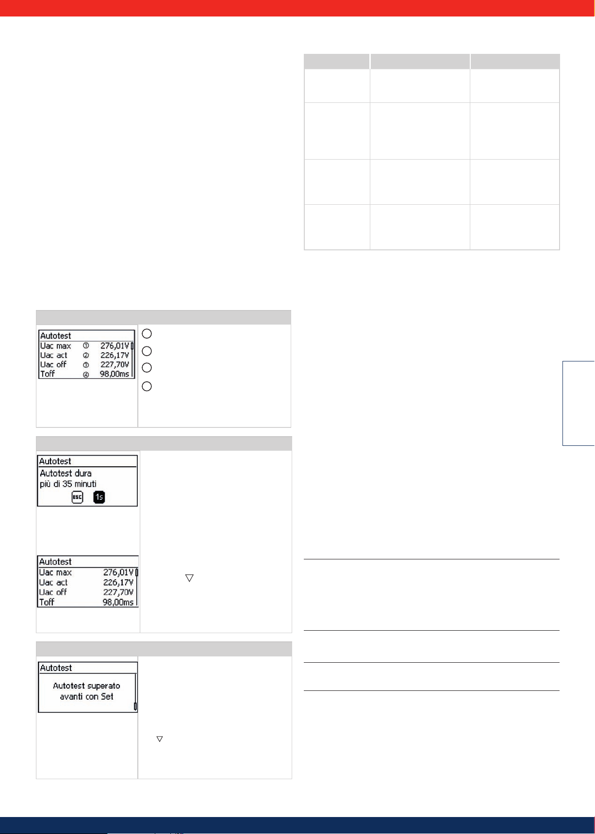
6.6 Autotest
Il quadro regolamentare italiano prevede che nel funzionamento dell'inverter sia
inclusa una funzione di autotest.
Funzionamento
Affinché l'autotest funzioni devono essere soddisfatti i requisiti seguenti:
• Durante la prima messa in funzione è stato impostato come paese l'Italia.
• L'irraggiamento solare è sufficiente perché l'inverter immetta la corrente in rete.
L'autotest ha la funzione di verificare il comportamento di distacco degli inverter in
relazione a valori troppo alti o troppo bassi di tensione e frequenza di rete
(6 sezioni di prova, durata ca. 40 minuti). Tenere presente i seguenti punti:
• A seconda della sezione di prova, durante l'autotest l'inverter modifica gradualmente la soglia di distacco portando i valori limite da basso/alto a alto/basso.
• Se la soglia di distacco raggiunge l'effettiva tensione e frequenza di rete,
l'inverter salverà i relativi dati rilevati.
• Tali dati verranno visualizzati sul display nel seguente modo:
- Dapprima saranno visualizzati i valori correnti della prima sezione di prova;
vedere la figura seguente p.16.
- I valori delle sezioni di prova seguenti compariranno al di sotto della prima
(inizialmente non visibili).
- Se l'autotest si è concluso con successo, in basso verrà inserito il messaggio
Autotest superato
to.
• Qualora i requisiti necessari all'autotest non dovessero essere soddisfatti, comparirà invece uno dei messaggi di stato riportati in Tabella 3.
• Se, durante l'autotest un valore di misura risulta al di fuori dall'intervallo di
tolleranza prescritto, l'autotest viene interrotto e l'inverter visualizza il messaggio Autotest fallito. L'inverter resta scollegato dalla rete (relè aperto,
nessuna immissione) fino a quando l'autotest non si è concluso con successo.
Modicare le impostazioni numeriche
Comando
. Tale messaggio deve essere visualizzato e conferma-
Valore soglia più basso/alto secondo impo-
1
stazione Paese
Effettiva tensione/frequenza di rete
2
misurata
3
Soglia di distacco (modificata gradual-
mente)
Tempo di distacco = intervallo di tempo tra
4
i seguenti eventi:
• La soglia di disinserzione raggiunge l'effettiva tensione/frequenza di rete
• l'inverter si stacca dalla rete
√ Il Paese impostato sull'inverter da esami-
nare è Italia .
1. Se necessario, verificare il Paese impostato
nel menu principale alla voce
Informazione Informazioni di
sistema.
2. Dal menu principale selezionare Autotest.
Compare la finestra di dialogo riportata
a sinistra.
3. Premere SET per 1 secondo. L'autotest
si avvia.
4. Vengono visualizzati i valori della prima
sezione di prova (fig. a sinistra).
5. Premere per visualizzare i valori relativi
alla sezione di prova successiva (non
appena disponibile).
6. Solo se compare Autotest fallito:
Premere SET per confermare il messaggio. Compare l'indicatore di stato.
Messaggi degli errori che impediscono l'autotest:
Messaggio
Rilevato un errore Non è stato possibile avviare
Irraggiamento solare troppo basso
Condizioni rete non
valide
ENS non pronto L'autotest non è stato avviato
Descrizione Rimedio
Contattare l'installatore
l'autotest a causa di un errore
interno.
L'autotest non si è avviato o
è stato interrotto a causa di
ridotto irraggiamento solare,
soprattutto nelle ore serali o
notturne.
L'autotest è stato interrotto
a causa di condizioni di rete
non valide, per es. tensione CA
troppo bassa.
poiché l'inverter non è ancora
pronto per il funzionamento.
se l'errore si verifica di
frequente.
Ripetere l'autotest durante
il giorno mentre l'inverter
immette in rete.
Ripetere l'autotest in
seguito.
Ripetere l'autotest alcuni
minuti più tardi, non
appena l'inverter è pronto
e immette in rete.
Tabella 3
7. Manutenzione
7.1 Manutenzione per i moduli fotovoltaici Solar
Frontier SF165-S/SF170-S
Un controllo visivo mensile e altamente raccomandabile per mantenere l'efficienza
dei moduli FV SF e la sicurezza del montaggio.
• Rimuovere sporcizia, foglie morte o deiezioni di uccelli dalla superficie dei
moduli e controllare che la superficie non sia visibilmente danneggiata. Non
utilizzare detergenti per pulire i moduli SF, in quanto potrebbero danneggiare
le guarnizioni.
• Non utilizzare spazzole dure per la pulizia. Usare solo un panno morbido per
rimuovere lo sporco dai moduli.
• Quando è richiesta la sostituzione di alcune parti, assicurarsi che l´installatore\
manutentore usi parti specificate dal fabbricante con le stesse caratteristiche
delle parti originali. Sostituzioni non autorizzate possono provocare incendi,
shock elettrici o altri rischi.
• Arrestare l´utilizzo dei moduli se si osservano danni o fenomeni inusuali. Prov-
vedere alla loro sostituzione immediatamente tramite personale qualificato.
7.2 Manutenzione sistema DC
Il sistema DC è esente da manutenzione. Si raccomanda tuttavia di controllare
regolarmente che i cavi e i connettori non siano danneggiati.
7.3 Manutenzione del Turbo inverter
L'inverter è praticamente esente da manutenzione. Tuttavia consigliamo di verificare regolarmente che non vi sia alcun deposito di polvere sulle alette di raffreddamento poste sul lato frontale e posteriore dell'apparecchio. Se necessario, pulire
l'apparecchio come descritto nel seguito.
Attenzione
Pericolo di danneggiamento di componenti.
• Non inserire detergenti e apparecchi di pulizia tra le alette di raffreddamento
(sotto la copertura grigia) sul lato frontale dell'inverter.
Non utilizzare in particolare i seguenti detergenti:
- detergenti a base di solventi
- disinfettanti
- detergenti granulari o apparecchi di pulizia appuntiti
ITALIANO
Comando
Attenzione
Se compare Autotest fallito ,eseguire
nuovamente l'autotest appena possibile, in
modo che l'inverter possa riprendere l'immissione in rete.
Una volta concluso l'autotest, procedere come
segue:
7. Premere ripetutamente finché compare
il messaggio
Autotest superato
8. Premere SET per confermare il risultato
dell'autotest. Compare l'indicatore di stato.
(fig. a sinistra).
Rimozione della polvere
Si consiglia di rimuovere la polvere con aria compressa (max. 2 bar).
Pericolo
Pericolo di morte a causa di scariche elettriche! Impiegare detergenti solo in combinazione con un panno leggermente umido.
Rimozione sporco persistente
Rimuovere lo sporco persistente con un panno leggermente umido (usare acqua
pulita). Se necessario, invece dell'acqua utilizzare una soluzione saponosa al 2%.
Al termine della pulizia, rimuovere eventuali tracce di sapone con un panno leggermente umido.
68
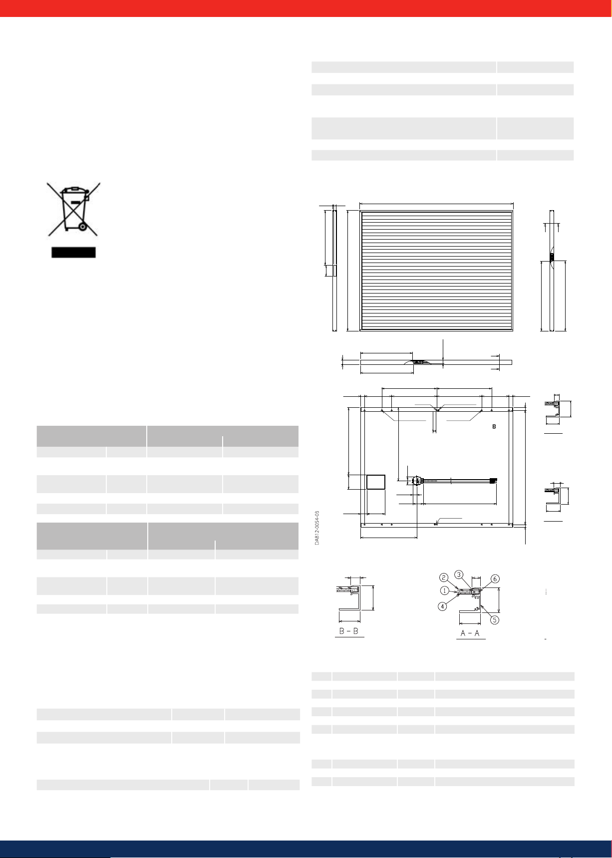
8. Magazzino e trasporto
A
(444)
±0
934
±2
598.5
±5
1200±100
2×Grounding
474.9
±5
88.1
66
47.8
21.5 21.5
120
(538.5)
150
(50)
31
±1
225 372.5
31
±1
225372.5
454.5 454.5
Mounting holes
Mounting holes
Label
8)
(-)
(+)
±2
4)
5 5
±5
4 9
±5
13.7
φ
φ
φ
φ
φ
φ
Seguire attentamente le istruzioni sull'imballo del modulo quando si immagazzinano e si trasportano i PowerSet SF. Per il loro immagazzinamento andrebbero preferiti
luoghi asciutti. L'imballaggio dei moduli non è impermeabile. Assicurarsi che durante
il trasporto e l'immagazzinamento i PowerSet restino al riparo da liquidi. I PowerSet
devono essere conservati nella confezione originale fino all'installazione finale.
È possibile che sui moduli aderisca una ridotta quantità di polverina bianca derivante dall'imballaggio. Questo non si ripercuote sulle prestazioni dei moduli e può
essere quindi trascurato.
9. Smaltimento
9.1 Smaltimento all'interno dell'UE
Questo segno sui moduli e sull'inverter indica che questi prodotti, a fine vita, non devono essere smaltiti con altri rifiuti domestici.
Per lo smaltimento e il riciclo si prega di portare i prodotti
in un centro di raccolta autorizzato, dove potranno essere
consegnati gratuitamente. In alcuni Paesi, è possibile in
alternativa consegnarli al rivenditore locale di riferimento
per i pezzi di ricambio.
Si prega di contattare le autorità locali per maggiori dettagli
sul punto di raccolta più vicino.
I cavi DC vanno smaltiti in loco assieme ai rifiuti elettrici.
La mancata osservanza delle regole può portare a sanzioni a seconda della legge
applicabile.
9.2 Smaltimento all'esterno dell'UE
Il simbolo del cassonetto della spazzatura cancellato con una croce è valido solo
nell'Unione Europea (UE). Se si desidera smaltire questo prodotto, contattare le
autorità locali o il rivenditore per informarsi sul metodo di smaltimento corretto.
10. Dati tecnici e schede tecniche
Dati meccanici
Dimensioni (Lunghezza × Larghezza × Altezza) 1.257 x 977 x 35 mm
Peso 20 kg / 16,3 kg/m²
Temperatura Operativa Modulo da -40 °C a 85 °C
Classe di applicazione in base a IEC 61730 Classe A
Classe di protezione antincendio in base a
Classe C
IEC 61730
Cavo
2,5 mm2 / AWG14
(senza alogeni)
Carico massimo neve (sulla parte anteriore del modulo) 2.400 Pa
Carico massimo vento (sul retro del modulo) 2.400 Pa
Disegno del modulo
±2
(7)
20
±2
90
977
±5
427.1
±0.5
35
449.9
±5
1257
B B
±5
565.5
(23 8)
A
±5
574.9
10.1 Moduli fotovoltaici Solar Frontier SF165-S/SF170-S
Caratteristiche elettriche
Condizioni di test standard (STC)*1
Modulo SF165-S Modulo SF170-S
Potenza nominale Pmax
Tensione a circui-
Voc
to aperto
Corrente di corto
Isc
circuito
Tensione nominale Vmpp
Corrente nominale Impp
Potenza nominale Pmax 123 W 126 W
Tensione a circuito
aperto
Corrente di corto
Voc
Isc
circuito
Tensione nominale Vmpp 80,2 V 82,1 V
Corrente nominale Impp 1,53 A 1,55 A
*1 Informazioni misurate in condizioni di test standard "STC", definite dallo standard IEC
(irraggiamento 1000 W/m² , temperatura del modulo 25°C, AM 1,5 con tolleranze di ±10%
per Isc e Voc e +10% / -5% per Pmax). L'efficienza del modulo sotto irraggiamento di 200
W/m² è tipicamente del 98% (±1.9%) dell'efficienza STC.
*2 Condizioni di temperatura nominali della cella (NOCT): Temperatura del modulo quando
lavora sotto 800 W/m2 di irraggiamento, temperatura dell'aria 20°C, velocità del vento
1m/s e a funzionamento a vuoto.
Caratteristiche Termiche
NOCT 47 °C
Coeciente di temperatura di Isc α +0,01 %/K
Coeciente di temperatura di Voc β -0,30 %/K
Coeciente di temperatura di Pmax δ -0,31 %/K
Caratteristiche per progettazione di sistema
Tensione massima di sistema Vsys 1.000 V DC
Limite corrente inversa Ir 7 A
165 W 170 W
110 V 112 V
2,20 A 2,20 A
85,5 V 87,5 V
1,93 A 1,95 A
Condizioni di funzionamento nominali
per la temperatura di cella (NOCT)*2
Modulo SF165-S Modulo SF170-S
100 V 102 V
1,76 A 1,76 A
13,5
35
30
4 × Ø 8.5
2 × Ø 4
4 × Ø 6.6
2 × Ø 4.5
12
35
30
Nr. Parte Quantità Descrizione
1 Cella 1 CIS su substrato di vetro
2 Vetro di copertura 1 Vetro temperato trasparente
3 Incapsulante EVA
4 Backsheet Strato plastico idrorepellente
5 Telaio 1 Set Lega alluminio anodizzato (colore nero)
6 Sigillante Butyl
7 Junction box 1 Con diodo di bypass
8 Cavo
2
2,5 mm
/ AWG14 (con connettore
Hosiden HSC - MC4 a innesto, a tenuta
stagna)
9 Adesivo Silicone
10 Etichetta 1 Etichetta di prodotto
11 Vite 8 Acciaio (SUS304J3)
Etichetta codice
12
a barre
1 Numero di serie
69
12
35
30
A-A
13 5
35
30
B-B

10.2 Dati tecnici del Turbo inverter
Turbo 1P Mini Turbo 1P Turbo 3P1 Turbo 3P2
Lato ingresso CC (collegamento generatore FV)
Numero degli ingressi CC 1 1 1 1
Tensione di avvio massima 420 V 845V 1000 V 1000 V
Tensione d'ingresso massima 420 V 845 V 1000 V 1000 V
Tensione d'ingresso minima per immissione 75 V 350 V 250 V 250 V
Tensione di avvio ingresso 90 V 350 V 250 V 250 V
Tensione d'ingresso nominale 255 V 540 V 510 V 790 V
Tensione minima per uscita nominale 180 V 360 V 375V 575 V
Tensione MPP 75 V … 350 V 360 V … 700 V 375 V … 700 V 575 V … 700 V
Corrente d'ingresso massima 11,5 A 12 A 11 A 11 A
Corrente d'ingresso nominale 8 A 8 A 8 A 8 A
Potenza d'ingresso massima con potenza attiva di
uscita massima
Potenza d'ingresso nominale (cos φ = 1) 2050 W 4310 W 4100 W 6330 W
Riduzione / limitazione della potenza automatica se:
Lato uscita CA (collegamento di rete)
Tensione in uscita (in funzione delle impostazioni del
Paese)
Tensione di uscita nominale 230 V 230 V 400 V 400 V
Corrente di uscita massima (corrente corto circuito) 12 A 18,5 A 7 A 10 A
Corrente di uscita nominale 8,7 A 18,3 A 3,3 A 5,2 A
Potenza attiva massima (cos φ = 1) 2000 W 4200 W 4000 W 6200 W
Potenza attiva massima (cos φ = 0,95) 2000 W 3990 W 3800 W 5890 W
Potenza apparente massima (cos φ = 0,95) 2100 VA 4200 VA 4000 VA 6200 VA
Potenza attiva massima (cos φ = 0,9) - - 3600 W 5580 W
Potenza apparente massima (cos φ = 0,9) - - 4000 VA 6200 VA
Potenza nominale 2000 W 4200 W 4000 W 6200 W
Frequenza nominale 50 Hz e 60 Hz
Tipo di rete
Frequenza di rete 45 Hz ... 65 Hz (in funzione delle impostazioni del Paese)
Potenza dissipata nel funzionamento Notturno < 2 W < 1 W < 3 W < 3 W
Fasi di immissione monofase monofase trifase trifase
Fattore di distorsione (cos φ = 1) < 2 % < 2 % < 1 % < 1 %
Fattore di potenza cos φ
Caratterizzazione del funzionamento
Efficienza massima
Efficienza europea 97,5 % 98,2 % 98,1 % 98,3 %
Efficienza CEC 97,6 % 98,2 % 98,4 % 98,5 %
Grado di rendimento MPP > 99,7 % (statico), > 99 %
Andamento del grado di rendimento (al 5 %, 10 %,
20 %, 25 %, 30 %, 50 %, 75 %, 100 % della potenza
nominale) con tensione nominale
Riduzione del grado di rendimento in caso di
aumento della temperatura ambiente (a temperature
> 40 °C)
Variazione del grado di rendimento in caso di scostamento dalla tensione nominale CC
Consumo proprio < 4 W < 4 W < 8 W < 8 W
Derating a potenza massima da 50 °C (T
Potenza di inserimento 10 W
Potenza di disinserzione 5 W 5 W 8 W 8 W
Sicurezza
Classe di protezione II
Principio di separazione nessuna separazione galvanica, senza trasformatore
Monitoraggio di rete sì, integrato
Monitoraggio dell'isolamento sì, integrato
Monitoraggio della corrente di guasto sì, integrato
Tipo di protezione contro la sovratensione varistori
2050 W 4310 W 4100 W 6330 W
• potenza d'ingresso a disposizione > potenza FV massima consigliata
• raffreddamento insufficiente
• corrente di ingresso troppo alta
• corrente di rete troppo alta
• riduzione potenza interna o esterna
• frequenza di rete troppo alta (secondo impostazione Paese)
• segnale limitazione a interfaccia esterna
• potenza di uscita limitata (impostazione sull'inverter)
185 V ... 276 V 185 V ... 276 V 320 V ... 480 V 320 V ... 480 V
L / N / FE (messa a terra funzionale )
0,95 capacitivo ... 0,95
induttivo
0,95 capacitivo ... 0,95
induttivo
L1 / L2 / L3 / N / FE L1 / L2 / L3 / N / FE
0,8 capacitivo ... 0,8
induttivo
0,8 capacitivo ... 0,8
induttivo
98,0 % 98,6 % 98,6 % 98,7 %
(dinamico)
92,8 %, 95,8 %, 97,3 %,
97,5 %, 97,7 %, 97,8 %,
97,7 %, 97,4 %
> 99,7 % (statico), > 99 %
(dinamico)
96,2 %, 97,6 %, 98,3 %,
98,3 %, 98,3 %, 98,2 %,
97,9 %, 97,4 %
> 99,8 % (statico), > 99 %
(dinamico)
91,0 %, 95,5 %, 97,5 %,
97,9 %, 98,1 %, 98,4 %,
98,6 %, 98,3 %
> 99,8 % (statico), > 99 %
(dinamico)
92,6%, 96,5%, 98,2%,
98,3%, 98,5%, 98,6%,
98,5%, 98,2%
0,005 %/°C
0,002 %/V
) da 45 °C (T
amb
1)
) da 50 °C (T
amb
) da 50 °C (T
amb
70
amb
ITALIANO
)

Turbo 1P Mini Turbo 1P Turbo 3P1 Turbo 3P2
Protezione contro l'inversione di polarità Sì
Condizioni di utilizzo
Ambito di utilizzo nei locali chiusi, climatizzati o non climatizzati
Temperatura ambiente (T
) −15 °C ... +60 °C −15 °C ... +60 °C −15 °C ... +60 °C −15 °C ... +60 °C
amb
Temperatura di stoccaggio -30 °C ... +80 °C -30 °C ... +80 °C -30 °C ... +70 °C -30 °C ... +70 °C
Umidità relativa
0 % ... 95 %, non condensante
Altitudine di installazione ≤ 2000 m s.l.m. NN
Grado di inquinamento PD3
Emissione rumori 31 dBA 31 dBA 29 dBA 29 dBA
Gas non consentiti nelle vicinanze dell'apparecchio ammoniaca, solventi
Dotazione ed esecuzione
Grado di protezione IP21 (Involucro: IP51; Display: IP21)
Categoria di sovratensione III (AC), II (DC)
Collegamento CC Phoenix Contact SUNCLIX (1 coppia)
Collegamento CA
Tipo connettore Wieland
RST25i3
Sezione dei collegamenti
Diametro cavi 10 ... 14 mm 2
Sezione trasversale ≤ 4 mm
connettore Wieland
RST25i3
2
connettore Wieland
RST25i5
connettore Wieland
RST25i5
Controspina compresa in dotazione
Dimensioni (X x Y x Z) 340 x 608 x 222 mm
Peso 8,3 kg 9 kg 10 kg 10 kg
Display display grafico 128 x 64 pixel
Interfaccia di comunicazione RS485 (n. 2 prese RJ45: collegamento PowerStorage, n. 1 presa RJ10: collegamento al contatore RTU Modbus),
Interfaccia Ethernet per PowerMonitoring (n. 1 RJ45)
Gestione dell'immissione secondo la legge tedesca
EinsMan-ready, attraverso interfaccia RS485
sulle energie rinnovabili EEG 2012
Interruttore sezionatore CC integrato sì, conforme VDE 0100-712
Principio di raffreddamento ventola termoregolata, a numero di giri variabile, interna (protetta contro la polvere)
Tabella 4
Data tecnici in 25 °C/ 77 °F.
1)
Grazie alla particolare struttura, l'inverter non causa la produzione di alcuna corrente di guasto continua.
10.3 Dati tecnici del cavo CA e dell'interruttore automatico di sicurezza
Inverter
Sezione del cavo
di linea CA
Turbo 1P Mini 1,5 mm
2,5 mm
4,0 mm
Turbo 1P 2,5 mm
4,0 mm
2
2
2
2
2
Potenza dissi-
1)
pata
18 W B16
11 W B16
6 W B16
48 W B25
30 W B25
Turbo 3P1 2,5 mm² 7 W B16
4,0 mm² 4 W B16
4,0 mm
2
2
13 W B16
8 W B16
Turbo 3P2 2,5 mm
1)
Potenza dissipata della linea AC alla potenza nominale dell'inverter e con cavo di
lunghezza 10 m.
Interruttore automatico di sicurezza
Tabella 5
10.4 Tabella dei Paesi
Per i dettagli sull'impostazione del Paese, vedere il paragrafo 5.4.7.
Turbo Inverter 1P Mini / 1P
Nota
Le linee guida per i parametri di rete specifici per il Paese possono essere modificate con breve preavviso. Contattate il supporto tecnico Solar Frontier se i parametri
indicati nella tabella non corrispondono più alle normative nazionali in vigore.
71

Valori della tensione
di distacco (valori di
2)
picco)
Valori della tensione
di distaccoø (valori
3)
medi)
Frequenza di distacco
4)
Paese
massima minima massima minima massima minima
Tempo di ripristino
Nome Display
Tensione nominale
1)
s V % s % s % s % s Hz Hz s Hz s
Frequenza nominale
Australia 6100 Australia 60 230 17,0 2,00 -13 2,00 – – – – 50 5,0 2,0 -5,0 2,0 no
Bulgaria 3590 Bâlgarija 30 230 15,0 0,20 -20 0,20 10 600 – – 50 0,2 0,2 -2,5 0,2 no
Belgio 2 3203 Belgique 2
5)
60 230 15,0 0,20 -20 0,20 10 600 – – 50 1,5 0,2 -2,5 0,2 no
Belgio 2 unlimited 3203 Belgique 2 unl. 60 230 15,0 0,20 -20 0,20 10 600 – – 50 1,5 0,2 -2,5 0,2 no
Brasile 220 5500 Brasil 220V 60Hz 300 220 10,0 0,20 -20 0,40 – – –
– 60 2,0 0,2 -2,5 0,2 sì
Brasile 230 5501 Brasil 230V 60Hz 300 230 10,0 0,20 -20 0,40 – – – – 60 2,0 0,2 -2,5 0,2 sì
Repubblica Ceca 42000 Česko 120 230 15,0 0,20 -15 0,20 10 600 – – 50 0,5 0,2 -0,5 0,2 no
Cipro 35700 Cyprus 180 230 10,0 0,50 -10 0,50 – – – – 60 2,0 0,5 -3,0 0,5 sì
Danimarca unlimited 4500 Danmark unl. 60 230 15,0 0,20 -20 0,20 10 600 – – 50 1,5 0,2 -2,5 0,2 sì
Danimarca 2 4501 Danmark
6)
60 230 15,0 0,20 -20 0,20 10 600 – – 50 1,5 0,2 -2,5 0,2 sì
Germania 4900 Deutschland 60 230 15,0 0,20 -20 0,20 10 600 – – 50 1,5 0,2 -2,5 0,2 sì
Estonia 3720 Eesti 300 230 15,0 0,20 -15 1,50
– – – – 50 1,0 0,5 -3,0 0,5 no
Irlanda 35300 Éire 30 230 10,0 0,50 -10 0,50 – – – – 50 0,5 0,5 -2,0 0,5 no
Spagna 3400 España 1699 180 230 15,0 0,20 -15 1,50 10 1,5 – – 50 0,5 0,5 -2,0 3,0 no
Francia 3300 France 30 230 15,0 0,20 -20 0,20 10 600 – – 50 0,6 0,2 -2,5 0,2 no
Grecia continentale 3000 Greece continent 180 230 15,0 0,50 -20 0,50 10 600 – – 50 0,5 0,5 -0,5 0,5 no
Grecia insulare 3001 Greece islands 180 230 15,0 0,50 -20 0,50 10 600, – – 50 1,0 0,5 -2,5 0,5 no
India 9100 India 300 230 35,0 0,05 -50 0,10 10 2,0 -15 2,0 50 1,0 0,2 -1,0 0,2 no
Israele 9720 Israel 300 230 35,0 0,05 -50 0,10 10
Italia 3 3902 Italia 3 30 230 22,0 0,10 -25 0,20 – – – – 50 5,0 0,2 -5,0 0,2 no
Italia 8 3907 Italia 8
Italia 9 3908 Italia 9
Italia 10 3908 Italia 10
Italia 11 3908 Italia 11
Costa Rica 5060
Ungheria 3600
7)
8)
7)
8)
Latinoamérica 60Hz
300 230 15,0 0,20 -15 0,40 10 600 -15 0,4 50 0,5 0,1 -0,5 0,1 no
300 230 15,0 0,20 -15 0,40 10 600 -15 0,4 50 0,5 0,1 -0,5 0,1 sì
300 230 15,0 0,20 -15 0,40 10 600 -15 0,4 50 0,5 0,1 -2,5 0,1 no
300 230 15,0 0,20 -15 0,40 10 600 -15 0,4 50 0,5 0,1 -2,5 0,1 sì
20 240 10,0 0,20 -20 0,20 – – – – 60 0,6 0,2 -0,6 0,2 no
Magyarország 300 230 35,0 0,05 -50 0,10 10 2,0 -15 2,0 50 1,0 0,2 -1,0 0,2 no
2,0 -15 2,0 50 1,0 2,0 -1,0 2,0 no
Malesia 6000 Malaysia 180 230 17,4 2,00 -13 2,00 – – – – 50 5,0 2,0 -5,0 2,0 no
Mauritius 23000 Mauritius 180 230 10,0 0,20 -6 1,50 6 1,5 – – 50 1,0 0,5 -3,0 0,5 no
Messico 5200 Mexico 300 240 35,0 0,05 -50 0,10 10 600 60 1,2 5,0 1,2 5,0 -1,2 5,0 sì
Paesi Bassi 3100 Nederland 30 230 10,0 2,00 -20 2,00 – – – – 50 1,0 2,0 -2,0 2,0 no
Austria 4300 Österreich 30 230 15,0 0,10 -20 0,20 12 600 – – 50 1,5 0,2 -2,5 0,2 sì
Polonia 4800 Polska 30 230 15,0 0,20 -15 1,50 10 600 – – 50 1,0 0,5 -3,0 0,5 no
Portogallo 35100 Portugal
20 230 15,0 0,20 -15 1,50 10 600 – – 50 1,0 0,5 -3,0 0,5 no
Slovenia 38600 Slovenija 30 230 15,0 0,20 -30 0,20 10 1,5 -15 1,5 50 1,0 0,2 -3,0 0,2 no
Sudafrica 2700 South Africa 60 230 20,0 0,16 -50 0,20 10 2,0 -15 2,0 50 2,0 0,5 -2,5 0,5 no
Svizzera 4100 Suisse 30 230 15,0 0,20 -20 0,20 10 600 – – 50 0,2 0,2 -2,5 0,2 no
Finlandia 35800 Suomi 30 230 10,0 0,20 -15 0,20 – – – – 50 1,0 0,2 -2,0 0,2 no
Svezia 4600 Sverige 30 230 15,0 0,20 -15 0,20 11 60 – – 50 1,0 0,5 -3,0 0,5 no
Tahiti 6890 Tahiti 60Hz 30 230 15,0 0,20 -20 0,20 10 600 – – 60 2,5 0,2 -5,0 0,2 no
Taiwan 220 8860 Taiwan 220V 60Hz 300
230 10,0 0,20 -12 0,20 – – – – 60 0,5 0,5 -0,5 0,5 no
Tailandia MEA 6600 Thailand MEA 300 230 20,0 0,16 -50 0,30 10 1,0 -10 2,0 50 1,0 0,1 -2,0 0,1 no
Tailandia PEA 6600 Thailand PEA 150 220 19,0 0,16 -50 0,30 10,2 1,0 -9,4 2,0 50 1,0 0,1 -2,0 0,1 sì
Turchia 9000 Türkiye 30 230 15,0 0,20 -20 0,20 10 600 – – 50 0,2 0,2 -2,5 0,2 no
Regno Unito
G59/3
Regno Unito
G83/1
Regno Unito
G83/2
4401 United Kingdom
(G59/3)
4402 United Kingdom
(G83/1)
4400 United Kingdom
(G83/2)
180 240 19,0 0,50 -20 0,50 14 1,0 -13 2,5 50 2,0 0,5 -3,0 0,5 no
20 230 14,7 1,5 -10 1,5 - - - - 50 2,0 0,5 -3,0 0,5 no
20 230 19,0 0,50 -20 0,50 14
1,0 -13 2,5 50 2,0 0,5 -3,0 0,5 no
EN 50438 -2014 50438 EN 50438:2014 60 230 15,0 0,20 -15 1,50 10 3,0 – – 50 2,0 0,5 -2,5 0,5 no
Droop Mode 0007 Droop-Mode 50Hz 60 230 20,0 0,50 -20 0,50 – – – – 50 5,0 0,5 -3,5 0,5 no
Droop Mode 60 0008 Droop-Mode 60Hz 60 230 20,0 0,50 -20 0,50 – – – – 60 5,0 0,5 -3,5 0,5 no
Regolazione potenza
reattiva
ITALIANO
Tabella dei Paesi
1)
Codici e nomi dei Paesi, così come visualizzati sul display.
2)
I valori di distacco corrispondono alla deviazione superiore e inferiore dai valori
di picco della tensione nominale (in %) e il corrispondente
tempo di distacco (in s).
3)
I valori di distacco corrispondono alla deviazione superiore e inferiore dai valori
medi della tensione nominale (in %) e il corrispondente tempo di distacco (in s).
4)
I valori di distacco corrispondono alla deviazione superiore e inferiore della
frequenza nominale (in Hz) e il tempo di distacco (in s).
5)
Potenza di uscita massima 3330 W
6)
Potenza di uscita massima 2000 W
7)
Impianti con potenza massima in uscita inferiore a 3 kW
8)
Impianti con potenza massima in uscita da 3 a 6 kW
Attenzione
Rischio di calo di rendimento. In sistemi collegati alla rete pubblica non è consentito impostare il Droop-Mode.
Si consiglia di selezionare il Droop-Mode quando l'inverter viene azionato in
combinazione con un inverter per impianti a isola all'interno di un sistema non
collegato alla rete pubblica.
72

Turbo Inverter 3P1 / 3P2
Nota
Le linee guida per i parametri di rete specifici per il Paese possono essere modificate con breve preavviso. A questo proposito, contattate il supporto tecnico Solar Frontier
se i parametri indicati nella tabella non corrispondono più alle normative nazionali in vigore.
Valori della tensione
di distacco (valori di picco)
2)
Valori della tensione
di distaccoø (valori
3)
medi)
Frequenza di distacco
4)
Paese
massima minima massima minima massima minima
Nome Display
Tensione nominale
Tempo di ripristino
1)
s V % s % s % s % s Hz Hz s Hz s
Frequenza nominale
Bulgaria 3590 Bâlgarija 30 400 15,0 0,20 -20 0,20 10 600 – – 50 0,2 0,2 -2,5 0,2
Belgio 2 unlimited 3203 Belgique 2 unl. 60 400 15,0 0,20 -20 0,20 10 600 – – 50 1,5 0,2 -2,5 0,2
Brasile 220 5500 Brasil 220V 300 380 10,0 0,20 -20 0,40 – – – – 60 2,0 0,2 -2,5 0,2
Brasile 230 5501 Brasil 230V 300 400 10,0 0,20 -20 0,40 – – – – 60 2,0 0,2 -2,5 0,2
Cipro 42000 Česko 30 400 15,0 0,20 -15 0,20 10 600 – – 50 0,5 0,2 -0,5 0,2
Repubblica Ceca 35700 Cyprus 180 400 10,0 0,50 -10 0,50 – – – – 50 2,0 0,5 -3,0 0,5
Danimarca unlimited 4500 Danmark unl. 60 400 15,0 0,20 -20 0,20 10 600 – – 50 1,5 0,2 -2,5 0,2
Germania 4900 Deutschland 60 400 15,0 0,20 -20 0,20 10 600 – – 50 1,5 0,2 -2,5 0,2
Droop Mode 0007 Droop-Mode 60 400 20,0 0,50 -20 0,50 – – – – 50 5,0 0,5 -3,5 0,5
Estonia 3720 Eesti 300 400 15,0 0,20 -15 1,50 – – – – 50 1,0 0,5 -3,0 0,5
Irlanda 35300 Éire 30 400 10,0 0,50 -10 0,50 – – – – 50 0,5 0,5 -2,0 0,5
EN 50438 :2007 50438 EN 50438:2007 20 400 15,0 0,20 -15 1,50 – – – – 50 1,0 0,5 -3,0 0,5
EN 50438 :2014 50438 EN 50438:2014 20 400 15,0 0,20 -15
1,50 10 3,0 – – 50 2,0 0,5 -2,5 0,5
Spagna 3400 España 1699 180 400 15,0 0,20 -15 1,50 10 1,5 – – 50 0,5 0,5 -2,0 3,0
Francia 3300 France 30 400 15,0 0,20 -20 0,20 10 600 50 0,6 0,2 -2,5 0,2
Grecia continentale 3000 Greece continent 180 400 15,0 0,50 -20 0,50 10 600 – – 50 0,5 0,5 -0,5 0,5
Grecia insulare 3001 Greece islands 180 400 15,0 0,50 -20 0,50 10 600 – – 50 1,0 0,5 -2,5 0,5
India 9100 India 300 400 35,0 0,05 -50 0,10 10 2,0 -15 2,0 50 1,0 0,2 -1,0 0,2
Italia 3 3902 Italia 3 30 400 22,0 0,10 -25 0,20 – – – – 50 5,0 0,2 -5,0 0,2
Malesia 6000 Malaysia 180 400 17,4 2,00 -13 2,00 – – – – 50 5,0 2,0 -5,0
Mauritius 23000 Mauritius 180 400 10,0 0,20 -6 1,50 6 1,5 – – 50 1,0 0,5 -3,0 0,5
Messico 5200 Mexico 300 415 35,0 0,05 -50 0,10 10 600 -15 600 60 1,2 5,0 -1,2 5,0
Paesi Bassi 3100 Nederland 30 400 10,0 2,00 -20 2,00 – – – – 50 1,0 2,0 -2,0 2,0
Austria 4300 Österreich 30 400 15,0 0,10 -20 0,20 12 600 – – 50 1,5 0,2 -2,5 0,2
Austria VN 4301 Österreich VN 30 400 15,0 0,10 -20 0,20 12 600 – – 50 1,5 0,2 -2,5 0,2
Polonia 4800 Polska 30 400 15,0 0,20 -15 1,50 10 600 – – 50 1,0 0,5 -3,0 0,5
Slovenia 38600 Slovenija 30 400 15,0 0,20 -30 0,20 10 1,5 -15 1,5 50 1,0 0,2 -3,0 0,2
Svizzera 4100 Suisse 30 400 15,0
0,20 -20 0,20 10 600 – – 50 0,2 0,2 -2,5 0,2
Finlandia 35800 Suomi 30 400 10,0 0,20 -15 0,20 – – – – 50 1,0 0,2 -2,0 0,2
Svezia 4600 Sverige 30 400 15,0 0,20 -15 0,20 11 60,0 – – 50 1,0 0,5 -3,0 0,5
Taiwan 220 8860 Taiwan 30 380 10,0 0,20 -12 0,20 – – – – 60 0,5 0,5 -0,5 0,5
Tailandia MEA 6601 Thailand MEA 300 230 50,0 0,30 -35 0,05 14 2,0 -5 2,0 50 1,0 0,1 -0,1 0,1
Tailandia PEA 6600 Thailand PEA 300 220 20,0 0,16 -50 0,30 10 1,0 -10 2,0 50 1,0 0,1 -2,0 0,1
Turchia 9000 Türkiye 30 400 15,0 0,20 -20 0,20 10 600 – – 50 0,2 0,2 -2,5 0,2
Tabella dei Paesi
1)
Codici e nomi dei Paesi, così come visualizzati sul display.
2)
I valori di distacco corrispondono alla deviazione superiore e inferiore dai valori
di picco della tensione nominale (in %) e il corrispondente tempo di distacco (in s).
3)
I valori di distacco corrispondono alla deviazione superiore e inferiore dai valori
medi della tensione nominale (in %) e il corrispondente tempo di distacco (in s).
4)
I valori di distacco corrispondono alla deviazione superiore e inferiore della
Tabelle 6
frequenza nominale (in Hz) e il tempo di distacco (in s).
2,0
Attenzione
Rischio di calo di rendimento. In sistemi collegati alla rete pubblica non è consentito impostare il Droop-Mode.
Si consiglia di selezionare il Droop-Mode quando l'inverter viene azionato in
combinazione con un inverter per impianti a isola all'interno di un sistema non
collegato alla rete pubblica.
73

10.5 Prese e spine
10.5.1 Informazioni di prodotto su prese e spine
Produttore: Hosiden
Prodotto: HSC2013 und HSC2014
Dati tecnici
Corrente nominale 30A DC / 6.0mm², 30A DC / 4.0mm²,
Tensione nominale 1000 V (IEC)
Test voltaggio 6 KV per 1 minuto, 10 kV impulso (1,2/50μS) (IEC)
Tipica resistenza di contatto massima 1m Ω
Materiale di contatto Lega di rame
Sistema di contatto creato a freddo stampato e formato con inster-
Materiale di isolamento Policarbonato
Sistema di serraggio Locking-Typ
Tensioni sul cavo a ghiandola di compressione
Grado di protezione IP67 (se accoppiato)
Classe di protezione II (IEC61140)
Grado di inquinamento 3 (IEC60664)
Categoria di sovratensione III (IEC60664)
Classe di fuoco UL94-VO
Range di temperature
ambiente
10.5.2 Informazioni di prodotto cavo CC
/ Requisiti minimi
(disponibile come optional)
Produttore: HIS
Prodotto: HIKRA® Plus o PlusXL
Questo cavo può essere fornito da Solar Frontier.
Se si utilizzano altri cavi, devono essere almeno equivalenti o soddisfare le seguenti specifiche tecniche e di costruzione.
Dati tecnici
Approvato DKE (PV1-F), TÜV 2 PfG. 1169/08.07 (R 60089447)
Temperatura di lavoro da -40 °C a +90 °C
Minimo raggio di curvatu-
ra essibile
Minimo raggio di curva-
tura sso
Tensione nominale [U0/U] AC 600 / 1.000 V | DC 900 / 1.500 V
Test voltaggio AC 6.500 V
Voltaggio no a 1,8 kV sono possibili (conduttore / conduttore,
Costruzione generale
Numero conduttori x
sezione in mm
Costruzione conduttore n
x max-ø (mm)
Diametro esterno ca.
(± 0,3 mm)
Peso ca. kg/km 38,4 57,6
Struttura
Rame stagnato, in fili sottili come da IEC 60228 classe 5
Polyolefin
Doppio isolamento
Isolamento / guaina esterna reticolata speciale
2
20A DC / 4.0mm²,
25A DC / 2.5mm², 15A DC / 2.5mm²
to RADSOK®
da -40 °C a 85 °C
10 x dia cavo
5 x dia cavo
sistema non a terra, circuito senza carico)
1 x 4,0 1 x 6,0
56 x 0,31 80 x 0,31
5,7 6,4
10.5.3 Informazioni prodotto cavi a Y
Produttore: HIS
Produkt: HISkon Splitter
Dati tecnici
Portata max. di corrente secondo IEC 60364-5-52 a 90°C
singolo, posa in aria libera*; senza connettore
* In caso di ammassamento utilizzare i fattori di riduzione di cui alla norma IEC 60364-5-52,
tabella A.52-17
Cavo principale 49,7 A
Cavo di diramazione 49,7 A
Tensione nominale 1000V DC
Resistività di massa sul giunto saldato:
Categoria di sovratensione III
Panoramica connettori per impianti fotovoltaici:
Classe di protezione (accoppiati) IIP67
portata max. di corrente 30 A (6,0 mm²)
temperatura max. d'impiego 90°C
Resistenza di contatto
< 0,1mΩ
1,0mΩ
11. Esclusione di responsabilità
Le informazioni contenute in questo manuale sono di proprietà di Solar Frontier
(SF). Nel caso in cui non venissero seguite le indicazioni di questo manuale,
le condizioni di garanzia perdono la loro validità. Solar Frontier non si assume
alcuna responsabilità per danni a cose e a persone, derivanti da un uso o montaggio improprio, così come da una cattiva messa in funzione e manutenzione.
Solar Frontier si riserva il diritto di modificare il contenuto di questo documento
senza preavviso. Questa versione del manuale di installazione e manutenzione è
valida da marzo 2016.
Le informazioni contenute in questo manuale di installazione e funzionamento
si basano sulle indicazioni dei fabbricanti dei singoli componenti al momento
della stampa del manuale, con riserva di errori e modifiche.
12. Contatti
Per reclami e problemi rivolgersi al proprio distributore locale dal quale si è
acquistato il prodotto. Vi supporterà per qualsiasi necessità.
Assistenza tecnica PowerSet Solar Frontier:
Numero
gratuito:
E-Mail:
Internet:
(02) 287 022 988
mail@pontiradiopr.it
www.solar-frontier.eu
ITALIANO
74

13. Appendici
13.1 Connettore CA del Turbo inverter
Informazioni importanti - Da leggere attentamente
Questo supplemento descrive l'installazione del connettore gesis RST a due e tre
poli. Tenere presente che i collegamenti elettrici e le installazioni devono essere
effettuati esclusivamente da professionisti esperti del settore.
Campo di applicazione e tipo di protezione antideagrante
• II 3 G Ex nA II, 80°C (T6)
• II 3 D Ex tD A22 T 85 °C (H05VV-F…: T 70 °C; H07RN-F…: T 60 °C)
N. certificato/Certificate No. SEV 07 ATEX 0110 X
Gamma estesa di applicazione per i seguenti dispositivi e connettori a vite:
• RST20I3S(D)S1 ZR.. / ..S(D)B1 ZR..
• RST20I3S(D)S1 M.. / ..S(D)B1 M..
Vedere anche “Condizioni particolari X”
Tipi di cavo
• H05VV-F… 1,5 mm2 e 2,5 mm
• H07RN-F… 1,5 mm2 e 2,5 mm
Speciche tecniche
Voltaggio fino 50 V, 250 V, 250/400 V
Sezione nominale 2,5 mm
Grado di protezione IP 66/68
Possono anche essere collegati conduttori a fili sottili e a filo singolo con 0,75 mm²
e 1,0 mm²
Corrente nominale
Dispositivi e collegamenti di rete, a vite e morsetti a molla
2
1,5 mm
2
2,5 mm
Cavi preassemblati
Tipo di cavo H05VV-F H07RN-F
2
1,5 mm
2
2,5 mm
Sezione trasversale (mm
Tecnica di avvitamento 1,5 4
Bloccaggio a molla 1,5 2,5
Tipi di cavo collegabili
Morsetto a vite filo singolo/fili sottili 1,5…2,5
– in aggiunta fili sottili 4,0
– in aggiunta Flessibile con manicotto
Morsetto senza viti a filo singolo 1,5…2,5
– in aggiunta flessibile con le estremità
– in aggiunta Flessibile con manicotto
Collegamento a
crimpare
Numero di cavi per terminale: 1 o 2
2
2
2
16 A
20 A
16 A 14,5 A
20 A 17,5 A
2
)
min. max.
terminale
dei conduttori saldate ad
ultrasuoni
terminale
flessibile con le estremità dei
conduttori saldate ad ultrasuoni
Sezione trasversale
2
(mm
)
1,5…2,5
1,5…2,5
1,5
1,5…2,5
Morsetti a molla
Conduttore PE N,L PE N,L
Collegamento semplice Collegamento doppio
Lunghezza di spellatura y (mm)
40 35 55 50
Lunghezza di isolamento x (mm)
2
Sezione trasversale (mm
) 1,5 2,5
a filo singolo 14,5+1 14,5+1
fili sottili (solo con boccole) 13+1
Manicotto terminale secondo DIN 46228-E-… 12
Saldato ad ultrasuoni 14,5+1 14,5+1
Collegamenti a vite
Tensioni sul cavo ø10…14 ø13…18
Conduttore PE N,L PE N,L
Collegamento semplice
Lunghezza di spellatura y (mm)
30 25 42 37
Collegamento doppio
45 40
Lunghezza di isolamento x (mm)
8 (Sezione trasversale 1,5…4 mm
2
)
Raggi di curvatura
Notare il raggio minimo di curvatura dei conduttori. Evitare forze di trazione nei
punti di contatto, effettuando le seguenti operazioni:
1. Piegare il cavo come
richiesto
2. Tagliare il cavo
3. Spellare il cavo e i fili.
Collegamento del cavo
Morsetto a molla
Collegamento a
vite:
Trasmissione PZ1,
Coppia di serraggio
tipo 0,8…1 Nm
Chiusura
Avvitamento:
Coppia di serraggio
tipo 4+1 Nm
Collegamento e bloccaggio
Lunghezze di spellatura e di isolamento (mm)
Pinza a compressione per
manicotto terminale
N. Art. 95.101.1300.0
75
ATTENZIONE
• I connettori non sono adatti per l'interruzione di corrente.
Non scollegare o collegare mai la connessione sotto carico!
• Al fine di poter garantire il rispetto del grado di protezione IP,
su tutti i connettori maschio o femmina inutilizzati non devono
essere montati tappi di protezione (accessori).

Apertura del connettore
1.
11,7 +0,2 mm
ø 25,5 ± 0,25 mm
Dettaglio
Sblocco e separazione
I connettori non sono adatti per l'interruzione di corrente.
Non scollegare o collegare mai la connessione sotto carico!
Smontaggio del conduttore
Dado:
Coppia di serraggio
tipo 2…2,5 Nm
Dettaglio
ATTENZIONE
Al fine di rispettare il grado di protezione IP68, assicurarsi, attraverso l'adozione
di misure adeguate, che i connettori siano protetti contro le forze di flessione
(ad es. non appendere carichi su cavo; giri di cavo non pendenti, ecc.)
ATTENZIONE
Cacciavite per morsetti a molla,
taglio secondo DIN 5264 A,
sfaccettato
1.
2.
Installazione in alloggiamento con passante M20
Dado:
Coppia di serraggio
tipo 3…3 ,5 Nm
NOTA
ITALIANO
1. I connettori per l'installazione RST 20i2…- i3…, secondo RL 94/9/EG
(Appendice ATEX 95), fanno parte del Gruppo di apparecchi II, categoria
3G, che, secondo RL 99/92/EG (ATEX 137), possono essere usati nella Zona
2 così come nei gruppi di gas IIA, IIB e IIC, che sono soggetti al rischio di
esplosione a causa di materiali combustibili nella gamma di classi di temperatura da T1 a T6. Durante l'uso/installazione, i requisiti di cui alla norma
EN 60079-14 devono essere rispettati.
2. I connettori per l'installazione RST 20i2…- i3…, secondo RL 94/9/EG
(Appendice ATEX 95), fanno parte anch'essi del gruppo di apparecchi II, categoria 3D, che, secondo RL 99/92/EG (ATEX 137), possono essere utilizzati
nella zona 22 di polveri combustibili. Durante l'uso/installazione, devono
essere rispettati i requisiti di cui alla norma EN 61 241-14.
3. Il campo di temperatura ambiente consentita è da -20°C a +40°C.
CONDIZIONI PARTICOLARI X
1. I connettori per l'installazione RST 20i2…- i3… possono essere installati
solo in luoghi in cui essi siano protetti dagli effetti di pericoli meccanici.
2. Le prese e le spine non necessarie devono essere chiuse con il pezzo di
chiusura relativo.
3. I cavi e le linee collegate con il connettore per l'installazione RST 20i2…- i3…
devono essere protetti da esposizione al rischio meccanico. Inoltre, l'installatore/operatore deve garantire uno scarico della trazione adeguato dei
cavi e delle linee.
4. Quando si utilizza un sezione del cavo >2,5mm2 e con una temperatura
ambiente fino a max. 70 °C, i connettori di installazione RST20i3 devono
essere utilizzati come dispositivi e connettori a vite con una corrente
massima di carico di 9,4 A.
5. I lavori di manutenzione e pulizia possono essere eseguiti solo in assenza
di atmosfera esplosiva.
Il caricamento elettrostatico dei connettori di installazione RST20i2...-i3…,
che si verifica ad esempio togliendo la polvere, deve essere evitato.
76

Informazioni importanti - Da leggere attentamente
Questo supplemento descrive l'installazione del connettore gesis RST a quattro e
cinque poli. Tenere presente che i collegamenti elettrici e le installazioni devono
essere effettuati esclusivamente da professionisti esperti del settore.
Tipi di cavo autorizzati
H05 W; H07 RN-F; Ölflex-Classic 100.
Nella tabella seguente sono elencati i tipi omologati UL:
Cord
Boccola piccola
Boccola media
Boccola larga
R/C (AVLV2/8)
Gamma AWM Cord OD
PVC jacket, Style 21098
8-10 mm
9.81 mm
10-12 mm
10,85 mm
12-14 mm
12,03 mm
Lunghezze di spellatura e di isolamento (mm)
Tensioni sul cavo ø 6...10 / 10...14 ø 13...18
Conduttore PE N,L PE N,L
Collegamento a vite
Lunghezza di spellatura y (mm) 30 25 55 50
Lunghezza di spellatura y
45 40
(doppio collegamento)
Lunghezza di spellatura x (mm) 8
(Sezione trasversale 1,5...4 mm
2
)
Collegamento a crimpare
Lunghezza di spellatura y 42 37 49 44
Lunghezza di spellatura x 7,0+1
(Sezione trasversale 0,75...4 mm
2
)
Utensile di crimpatura (per tutte le sezioni trasversali)
Pinza di base N. d'ordine 95.101.0800.0
Matrici di crimpatura N. d'ordine 05.502.2100.0
Raggi di curvatura
Notare il raggio minimo di curvatura dei conduttori. Evitare forze di trazione nei
punti di contatto, effettuando le seguenti operazioni:
1. Piegare il cavo come
richiesto
2. Tagliare il cavo
3. Spellare il cavo e i fili.
ATTENZIONE
Quando si utilizza lo sblocco manuale, la certificazione secondo VDE 0606
decade, poiché il connettore viene aperto senza attrezzi.
La prescrizione VDE 0627 rimane però invariata ed è del tutto valida.
Chiusura
Avvitamento:
Coppia di serraggio
tipo 4+1 Nm
Collegamento e bloccaggio
ATTENZIONE
• I connettori non sono adatti per l'interruzione di corrente.
Non scollegare o collegare mai la connessione sotto carico!
• Al fine di poter garantire il rispetto del grado di protezione IP,
su tutti i connettori maschio o femmina inutilizzati non devono
essere montati tappi di protezione (accessori).
Sblocco e separazione
Dettaglio
Collegamento del cavo
Collegamento a vite:
Trasmissione PZ1,
Coppia di serraggio tipo 0,5 Nm
Installazione dello sblocco manuale (opzionale)
Lo sblocco manuale permette di separare il connettore senza utensili.
Sede dello sblocco
manuale:
ATTENZIONE
I connettori non sono adatti per l'interruzione di corrente. Non
scollegare o collegare mai la connessione sotto carico!
1.
Dettaglio
77

Installazione in alloggiamento con passante M16 e M20
r (mm) D (mm)
M16 6,8-0,2 17 ± 0,15 mm
M20 8,7-0,2 21 ± 0,15 mm
Dado:
Coppia di serraggio
tipo 2,5…3 Nm
Installazione in alloggiamento con passante M25
11,7 -0,2 mm
ø 25,5 ± 0,15 mm
Dado:
Coppia di serraggio
tipo 2,5…3 Nm
ATTENZIONE
Al fine di rispettare il grado di protezione IP68, assicurarsi, attraverso l'adozione
di misure adeguate, che i connettori siano protetti contro le forze di flessione
(ad es. non appendere carichi su cavo; giri di cavo non pendenti, ecc.)
13.2 Connettore SunClix
Connettori fotovoltaici SUNCUX per l'impiego in impianti fotovoltaici per
2,5-5 mm
UL (ZKLA), AWG 10-14
1 Precauzioni di sicurezza
AVVERTENZA: I connettori SUNCLIX possono essere collegati esclusivamente da
elettrotecnici specializzati.
AVVERTENZA: Non scollegare o collegare mai i connettori SUNCLIX sotto carico.
Attenzione: Utilizzare questo connettore solo con un cavo solare 2,5-6 mm
tipo PV1-F o un cavo solare con certificazione UL (filo in rame ZKLA, AWG 10 - 14).
Solo con questo cavo è garantito un collegamento elettrico in sicurezza. Altri tipi
di cavo sono disponibili su richiesta. Durante la posa del cavo, fare attenzione al
raggio di curvatura definito dal produttore.
ATTENZIONE: Collegare questo connettore solo con altri connettori SUNCLIX.
Durante il collegamento, fare attenzione alle informazioni essenziali su tensione
nominale e corrente nominale. Il valore minimo comune è permesso.
ATTENZIONE: Proteggere i connettori da umidità e sporcizia.
- Non immergere i connettori nell'acqua.
- Non posizionare il connettore direttamente sulla copertura del tetto.
- Dotare i connettori non collegati di un cappuccio di protezione (ad es. PV-C
2 Collegare il connettore
2.1 Collegare il cavo (gura 35)
• Isolare il cavo con un attrezzo adatto, per 15 mm. Assicurarsi di non tagliare cavi
1 Introdurre attentamente il cavo spellato con i fili intrecciati fino al punto d'arre-
2 Chiudere la molla. Assicurarsi che la molla sia saldamente bloccata.
3 Far scorrere l'inserto nella boccola.
4 Serrare il pressacavo con 2 Nm.
2.2 Unire i connettori
• Unire i connettori maschio e femmina. A questo punto, il collegamento scatta.
• Stringere il giunto per verificare la corretta connessione.
3 Scollegare il connettore (gura 36)
È necessario un cacciavite a taglio con lama di 3 mm di larghezza
(ad es. SZF 1-0,6x3,5, 1204517).
1 Inserire il cacciavite come mostrato in Figura 36.
2 Lasciare il cacciavite inserito e scollegare i connettori maschio e femmina tra di
3.1 Scollegamento del cavo (gura 37)
1 Allentare il pressacavo.
2 Inserire il cacciavite come mostrato in Figura 37.
3 Fare leva sul collegamento e separare il manicotto dall'inserto.
4 Aprire la molla con un cacciavite. Rimuovere il cavo.
2
- cavo solare di tipo PV1-Foder per cavi solari con certicazione
PROTECTION CAP, 1785430).
singoli.
sto. Le estremità del filo devono essere visibili nella molla.
loro.
2
di
ITALIANO
Figura 35
Figura 37
Figura 36
Speciche secondo la norma
EN 50521 UL SUBJECT 6703
Temperatura ambiente -40°C...+85 °C -40°C...+70 °C
Tensione nominale, max. 1100 VDC 600 VDC
Corrente nominale, max.
2
- 27 A; 4 mm2 -
2,5 mm
40 A; 6 mm2 - 40 A
AWG 14 - 15 A, AWG 12 20 A, AWG 10 - 30 A
Diametro del cavo 5 ... 8 mm 5 ... 8 mm
78

Inhoud
1. Algemene veiligheidsaanwijzingen 80
1.1 Veiligheidsaanwijzingen fotovoltaïsche module Solar Frontier SF170-S 80
1.2 Veiligheidsaanwijzingen Turbo omvormer 80
2. Bedoeld gebruik 80
3. Leveromvang en opbouw van de PowerSets 80
4. Over deze handleiding 81
4.1 Inhoud 81
4.2 Doelgroep 81
4.3 Aanduidingen 81
4.3.1 Symbolen 81
4.3.2 Signaalwoorden 81
4.3.3 Aanduidingen in de tekst 81
4.3.4 Afkortingen 82
5. Installeren 82
5.1 Montagesysteem / onderconstructie 82
5.2 Mechanisch installeren fotovoltaïsche module Solar Frontier SF170-S 82
5.2.1 Opname op de montagelocatie 82
5.2.2 Bedieningsinstructies 82
5.2.3 Aanwijzingen voor de montage 82
5.3 Elektrisch installeren fotovoltaïsche generator 84
5.3.1 Elektrische veiligheidsaanwijzingen 84
5.3.2 Op maat maken van kabels 84
5.3.3 Aarding 85
5.3.4 Elektrische bekabeling 85
5.4 Installeren Turbo omvormer 86
5.4.1 Veiligheidsmaatregelen bij het installeren 86
5.4.2 Omvormer monteren 86
5.4.3 AC-aansluitingen voorbereiden 86
5.4.4 DC-aansluitingen voorbereiden 87
5.4.5 Dataverbindingskabels voor Power Monitoring voorbereiden 87
5.4.6 Aansluiten van een PowerStorage-systeem 87
5.4.7 Modbus RTU-dataverbindingskabel voor
het aansluiten van een energiemeter 87
5.4.8 Omvormer aansluiten en AC inschakelen 87
5.4.9 Eerste inbedrijfstelling van de omvormer 87
5.4.10 DC inschakelen 89
5.4.11 Energiebeheer of PowerStorage 89
5.4.12 Registratie en instellen van PowerMonitoring 89
5.4.13 Omvormer demonteren 89
6. Opbouw en werking Turbo omvormer 90
6.1 Behuizing 90
6.2 Bedieningsknoppen 90
6.3 Overzicht bedieningsfuncties 91
6.4 Service-menu 91
6.5 Verhelpen van storingen 92
7. Onderhoud 94
7.1 Onderhoud fotovoltaïsche module Solar Frontier SF170-S 94
7.2 Onderhoud DC-systeem 94
7.3 Onderhoud Turbo omvormer 94
8. Transport en opslag 94
9. Recycling 94
9.1 Recycling binnen de EU 94
9.2 Recycling buiten de EU 94
10. Technische gegevens en gegevensbladen 94
10.1 Fotovoltaïsche module Solar Frontier SF170-S 94
10.2 Technische gegevens Turbo omvormer 96
10.3 Technische gegevens AC-leiding en leidingbeveiligingsschakelaar 97
10.4 Landentabel 97
10.5 Stekker & contrastekker 100
10.5.1 Productinformatie stekker & contrastekker 100
10.5.2 Productinformatie DC-kabel / Minimale vereisten 100
10.5.3 Productinformatie Y-kabel 100
11. Uitsluiting van aansprakelijkheid 100
12. Contact 100
13. Bijlagen 101
13.1 AC-stekker Turbo omvormer 101
13.2 SunClix stekkerverbinding 104
79

1. Algemene veiligheidsaanwijzingen
Gelieve alle noodzakelijke voorzorgsmaatregelen te treffen, om alle mogelijke ongevallen te voorkomen. De PowerSets mogen niet worden gebruikt voor systemen
waarvan de betrouwbaarheid invloed heeft op het leven of de lichamelijke integriteit van mensen, vooral niet voor de luchtvaart, medische uitrusting, verkeersregelsystemen en dergelijke.
Gebruik de PowerSets uitsluitend voor de bedoelde toepassing. Solar Frontier
raadt uitdrukkelijk aan de volgende aanwijzingen op te volgen, om materiële
schade en letsel of in het ergste geval de dood te voorkomen.
De door Solar Frontier Europe GmbH verkochte PowerSets dienen te worden
geïnstalleerd door bevoegd en geschoold personeel (zie 4.2). Wanneer
wordt geconstateerd dat een gevaarloos gebruik niet meer mogelijk is
(bijv. bij zichtbare beschadigingen), dient de PowerSet direct van het net te
worden gescheiden.
1.1 Veiligheidsaanwijzingen fotovoltaïsche module
Solar Frontier SF170-S
• Alleen personeel dat een licentie heeft en is opgeleid, mag het installeren,
bekabelen en onderhoud van SF-modules uitvoeren.
• Alle aanwijzingen en waarschuwingen m.b.t. de SF-modules, evenals alle
aanwijzingen van de fabrikant van systeemcomponenten moeten voor het
installeren en voor het gebruik zorgvuldig worden doorgelezen en begrepen.
• Om het gevaar voor elektrische schokken te verminderen, moet de voorkant
van de SF-modules tijdens het installeren worden afgedekt met niet lichtdoorlatend materiaal.
• SF-modules genereren pure gelijkstroom (DC).
• SF-modules kunnen geen elektrische energie opslaan.
• Het in serie schakelen van SF-modules produceert een hogere spanning en
een parallelschakeling een hogere stroom.
• Gebruik altijd SF-modules met dezelfde elektrische waarden in serie- resp. parallel-
schakeling, om systeemonbalans of beschadiging van de modules te voorkomen.
• De open spanning van een PV-array mag de maximale systeemspanning nooit
overschrijden, bijv. bij lage temperatuur
• Te hoge lekstromen kunnen stroomstoten of brandgevaar veroorzaken.
• Maak de aansluitkabels van in bedrijf zijnde modules nooit los. Dit kan leiden
tot het ontstaan van vlambogen, die tot zwaar letsel of de dood kunnen leiden.
• Gebruik de SF-modules uitsluitend voor het genereren van stroom in aardge-
bonden toepassingen, om elektrische schokken, brand of andere ongevallen
te voorkomen.
• Concentreer zonlicht niet kunstmatig met lenzen of spiegels op de modules.
• Gebruik geen andere stralingsbronnen, maar uitsluitend natuurlijk zonlicht of
omgevingsverlichting voor het genereren van stroom.
• Gebruik SF-modules niet in een natte omgeving. Het contact met water of vloeistof
verhoogt het risico op stroomstoten aanzienlijk.
• Uit veiligheidsoverwegingen mogen de lekstromen de bovengrens die is
voorgeschreven door de lokale autoriteiten niet overschrijden.
• Controleer de polariteit van de aansluitingen voor het installeren zorgvuldig.
Een verkeerde bekabeling kan de SF-modules of de verbruikers beschadigen.
• Gebruik uitsluitend gereedschappen, stekkers, kabels en montagesteunen die
geschikt zijn voor solarsystemen.
• Tijdens het uitvoeren van werkzaamheden aan SF-modules moet vooral bij
DC-spanningen hoger dan 30 V geschikte beschermende kleding worden gedragen. Bovendien moeten alle noodzakelijke veiligheidsmaatregelen worden
getroffen om stroomstoten te voorkomen.
1.2 Veiligheidsaanwijzingen Turbo omvormer
• Installeer en gebruik het apparaat pas, nadat u dit document hebt gelezen en
begrepen.
• Voer de in dit document beschreven maatregelen altijd uit in de opgegeven
volgorde.
• Bewaar dit document tijdens de levensduur van het apparaat. Geef het document door
aan de volgende eigenaren en gebruikers.
• Door ondeskundige bediening kan de opbrengst van het fotovoltaïsch sys-
teem worden verminderd.
• Met een beschadigde behuizing mag het apparaat niet zijn aangesloten op de
DC- of AC-leidingen.
• Stel het apparaat direct buiten werking en scheid het van het net en de solar-
modules, als een van de volgende componenten is beschadigd:
- Apparaat (werkt niet, zichtbare beschadigingen, rookontwikkeling, binnenge
drongen vloeistof, etc.)
- Leidingen
- Solarmodule(s)
• Het systeem mag niet eerder worden ingeschakeld tot
- het apparaat door de dealer of fabrikant is gerepareerd.
- beschadigde kabels of solarmodules door een vakman zijn gerepareerd.
• Apparaat nooit afdekken.
• Behuizing niet openen: Levensgevaar! Alle aanspraak op garantie vervalt!
• Vanuit de fabriek aangebrachte typeplaatjes en aanduidingen nooit wijzigen,
verwijderen of onleesbaar maken.
.
• Volg de handleiding van de betreffende fabrikant als u een externe compo-
nent aansluit die niet in dit document is beschreven (bijv. externe dataloggers).
Verkeerd aangesloten componenten kunnen de omvormer beschadigen.
Veiligheidsaanwijzingen op het apparaat:
1
1
1
Op de onderdelen kunnen tot wel 10 min. na uitschakeling van de DC-last-
scheidingsschakelaar en leidingbeveiligingsschakelaar gevaarlijke spanningen
aanwezig zijn.
Handleiding opvolgen!
2
3
Serienummer in tekst en als barcode
2
3
Afbeelding 1
2. Bedoeld gebruik
De PowerSet mag uitsluitend in aan het net gekoppelde fotovoltaïsche systemen
worden gebruikt. Omvormer, fotovoltaïsche modules, kabels, stekkers en contrastekkers zijn op elkaar afgestemd. De aansluitingen mogen niet worden geaard.
3. Leveromvang en opbouw van de PowerSets
Elke Solar Frontier PowerSet bestaat uit de volgende losse componenten.
Het aantal van de betreffende componenten kunt u vinden in de lijst in de bijlage
op basis van de typeaanduiding van uw PowerSet.
1
Fotovoltaïsche module Solar Frontier SF170-S
2
Solar Frontier Turbo 1P Mini / 1P / 3P1 / 3P2 omvormer (incl. omvormer,
montageplaat 1 paar SunClix stekkerverbindingen en AC-stekker)
3
Y-kabel, uitvoering voor (+) en (-)
4
DC-stekkers en DC-contrastekkers (in verpakkingseenheid van 3 stuks)
5
Installatie- en onderhoudshandboek
NEDERLANDS
80

Oppervlak
15,6 m² PowerSet Mini 2.0-170-1p 2.04 kWp 12 x SF170-S 1 x Turbo 1P Mini 1ph 3 (+) & 3 (-) 3 + 3 3
18,2 m² PowerSet Turbo 2.4-170-1p 2,38 kWp 14 x SF170-S 1 x Turbo 1P 1ph 1 (+) & 1 (-) 3 + 3 7
23,4 m² PowerSet Turbo 3.1-170-1p 3,06 kWp 18 x SF170-S 1 x Turbo 1P 1ph 2 (+) & 2 (-) 3 + 3 6
23,4 m² PowerSet Turbo 3.1-170-3p 3,06 kWp 18 x SF170-S 1 x Turbo 3P1 3ph 2 (+) & 2 (-) 3 + 3 6
26,0 m² PowerSet Turbo 3.4-170-1p 3,40 kWp 20 x SF170-S 1 x Turbo 1P 1ph 3 (+) & 3 (-) 3 + 3 5
27,3 m² PowerSet Turbo 3.6-170-1p 3,57 kWp 21 x SF170-S 1 x Turbo 1P 1ph 2 (+) & 2 (-) 3 + 3 7
31,2 m² PowerSet Turbo 4.1-170-1p 4,08 kWp 24 x SF170-S 1 x Turbo 1P 1ph 3 (+) & 3 (-) 3 + 3 6
31,2 m² PowerSet Turbo 4.1-170-3p 4,08 kWp 24 x SF170-S 1 x Turbo 3P1 3ph 3 (+) & 3 (-) 3 + 3 6
36,4 m² PowerSet Turbo 4.8-170-1p 4,76 kWp 28 x SF170-S 1 x Turbo 1P 1ph 3 (+) & 3 (-) 3 + 3 7
39,0 m² PowerSet Turbo 5.1-170-3p 5,10 kWp 30 x SF170-S 1 x Turbo 3P2 3ph 4 (+) & 4 (-) 6 + 6 6
45,5 m² PowerSet Turbo 6.0-170-3p 5,95 kWp 35 x SF170-S 1 x Turbo 3P2 3ph 4 (+) & 4 (-) 6 + 6 7
54,6 m² PowerSet Turbo 7.1-170-3p 7,14 kWp 42 x SF170-S 1 x Turbo 3P2 3ph 5 (+) & 5 (-) 6 + 6 7
62,4 m² PowerSet Turbo 8.2-170-1p 8,16 kWp 48 x SF170-S 2 x Turbo 1P 1ph 6 (+) & 6 (-) 6 + 6 6
Op de PowerSets afgestemde toebehoren kunnen apart bij Solar Frontier verkregen worden: DC-kabel. Montageframe en bevestigingsmateriaal. Gereedschap voor de
montage en het op maat maken van de kabels...
PowerSet
aanduiding Vermogen Modules Omvormer Netaansluiting Y-kabel
Stekkers &
contrastekkers
Modules
in serie
Schematische opbouw, bijvoorbeeld van een
PowerSet Turbo 3.1
PV-generator
Y-kabel
DC-kabel met stekker en contrastekker
Omvormer
Afbeelding 2
4. Over deze handleiding
4.1 Inhoud
Deze handleiding bevat alle informatie die een vakman nodig heeft voor het
instellen en gebruiken van een PowerSet.
Volg bij de montage van de overige componenten (bijv. AC-kabels, montagesysteem) de handleidingen van de betreffende fabrikant.
4.2 Doelgroep
Doelgroep van deze handleiding zijn vaklieden en installateurs, voor zover dit niet
anders is aangegeven.
Met vaklieden worden hier personen bedoeld die onder andere:
• beschikken over de kennis van de betreffende begrippen en vaardigheden
voor het instellen en gebruiken van fotovoltaïsche systemen.
• door vakopleiding, kennis en ervaring, evenals kennis van de geldende
bepalingen, de volgende werkzaamheden kunnen beoordelen en mogelijke
gevaren kunnen herkennen:
- Monteren van elektrische apparaten
- Op maat maken en aansluiten van dataleidingen
- Op maat maken en aansluiten van stroomtoevoerleidingen
4.3 Aanduidingen
4.3.1 Symbolen
Symbool
Algemene waarschuwing voor gevaar Handleiding
Voor gebruik van het product de
4.3.2 Signaalwoorden
In combinatie met de hierboven beschreven symbolen gebruikte signaalwoorden:
Signaalwoord Beschrijving
Gevaar Direct gevaar voor de dood of zwaar lichamelijk letsel
Waarschuwing
Voorzichtig
Let op! Mogelijke materiële schade
Opmerking Opmerking m.b.t. de bediening of het gebruik van de handleiding
Mogelijk gevaar voor de dood of zwaar lichamelijk letsel
Mogelijk gevaar voor licht of middelmatig lichamelijk letsel
4.3.3 Aanduidingen in de tekst
Aanduidingen Beschrijving
√ Voorwaarde voor een handeling
1., 2., 3., ...
Cursief Accentuering, licht
Vet Accentuering, sterk
Courier
Beschrijving Locatie
Gevaar door elektriciteit
handleiding lezen.
Individuele instructiestap
Meerdere instructiestappen in volgorde
Aanduiding van productelementen, zoals knoppen,
weergaven, bedrijfstoestanden
Handleiding /
apparaat
Apparaat
81

4.3.4 Afkortingen
Afkorting Beschrijving
A
AC
DC Gelijkspanning
Derating Vermogensreductie
DHCP
ENS
FE Foutstroom
l Stroomsterkte
l
k
I
mpp
kVA Kilovoltampere
kW Kilowatt
kWh Kilowattuur
m Meter
2
m
MPP
MPP-Tra
Nm Newtonmeter
P Elektrisch vermogen
Pa Pascal
PV Photo Voltaïc (fotovoltaïsch)
SELV, TBTS,
MBTS
SF Solar Frontier
STC Standaard testcondities
U Spanning
U
L
U
mpp
U
PV
V Volt
2
W/m
η Rendement
Stroomsterkte in ampère
Wisselspanning
Via DHCP wordt het apparaat automatisch opgenomen in een
bestaand netwerk (Engels: Dynamic Host Configuration Protocol)
Interne netbewaking van omvormer (Duits: "Einrichtung zur
Netzüberwachung mit zugeordneten Schaltorganen").
Kortsluitstroom
Stroom bij maximum power point
Vierkante meter
Werkpunt met hoogste vermogensopbrengst (Engels: maximum
power point)
cker
Regelt het vermogen van de aangesloten modulestrangen op het MPP
Veiligheidslaagspanning (EN: Safety Extra Low Voltage; FR: Très
Basse Tension de Sécurité; ES: Muy Baja Tensión de Seguridad)
Open spanning
Spanning bij maximum power point
Bij DC-aansluiting aanwezige spanning van generator (fotovolta-
ische spanning)
Watt per vierkante meter
5. Installeren
Voor een veilige montage moeten alle relevante nationale en lokale wetten, voorschriften en richtlijnen, vooral voor ongevallenpreventie, evenals
alle technische normen worden opgevolgd.
5.1 Montagesysteem / onderconstructie
De PowerSets worden standaard geleverd zonder montagesysteem. Bij Solar Frontier kan een geschikt montagesysteem als apart toebehoren verkregen worden.
Meer informatie hierover vindt u op www.solar-frontier.eu. Doorgaans zijn alle
in de handel verkrijgbare montagesystemen geschikt die een montage volgens
de specificaties in 5.2.3. waarborgen. Uw installateur zal een geschikte oplossing
kunnen voorstellen.
5.2 Mechanisch installeren fotovoltaïsche module
Solar Frontier SF170-S
5.2.1 Opname op de montagelocatie
• Controleer of door de lokale omstandigheden de maximale sneeuw- en
windbelastingen de gespecificeerde belastingsgrenzen van de SF-modules
niet overschrijden.
• Installeer de SF-modules niet op gebruikslocaties waar ze worden blootgesteld
aan oliedampen of corrosieve gassen.
• Vervuiling van de modules door zand, stof etc. moet worden vermeden, omdat
hierdoor de energieopbrengst kan dalen.
• Stel de SF-modules niet bloot aan zwavelhoudende atmosferen.
• Installeer de SF-modules niet op locaties waar ontvlambare gassen stromen of
zich kunnen verzamelen, omdat er vonkvorming kan ontstaan.
• Installeer de SF-modules niet in de buurt van vuur.
• Vermijd het installeren van de SF-modules op locaties die permanent in de
schaduw liggen, omdat het vermogen hierdoor nadelig kan worden beïnvloed.
• Installeer SF-modules niet op gebruikslocaties met temperaturen boven het in
de productspecificatie vermelde, toelaatbare temperatuurbereik.
5.2.2 Bedieningsinstructies
• Demonteer SF-modules niet in onderdelen en bouw ze niet om, omdat hier-
door stroomstoten, brand of andere ongevallen kunnen ontstaan. Solar Frontier is niet aansprakelijk voor verliezen of schade die door het ontoelaatbaar
demonteren in onderdelen, modificeren of misbruik van de modules ontstaan.
• Boor geen extra gaten in het aluminium frame. Alleen de aanwezige boringen
mogen worden gebruikt.
• Vermijd mechanische spanningen bij de modules, kabels of aansluitdozen.
(Voor de modulekabels worden een buigradius van minimaal 39 mm aanbevolen).
• Ga nooit op de SF-modules staan en stap er nooit op. U kunt hierbij letsel
oplopen en de module beschadigen.
• Laat de SF-modules niet vallen. Voorkom ook dat er andere voorwerpen op val-
len. Beide zijden van de module (voor- en achterkantafdekking) zijn breekbaar.
• Draag de module niet aan de aansluitdoos of kabels. Aansluitdoos en aan-
sluitkabels kunnen hierbij beschadigen en gevolgschade evenals gevaren
veroorzaken.
• Zorg dat er geen krassen komen op de achterafdekking en de kabels van de
SF-modules. Wrijving of krassen kunnen stroomstoten, lekstromen of ongevallen veroorzaken.
• Maak geen krassen op de isolerende coating van het frame (behalve op de
locatie voor de aardaansluiting), om de stabiliteit van het frame niet nadelig te
beïnvloeden en geen corrosie te veroorzaken.
• Laat de waterdrainagegaten vrij, om mechanische spanningen door vorst te
voorkomen.
• Sluit de aansluitdoos niet af met lijm. Gebruik ook geen afdichtkit bij het plaat-
sen van het deksel op de aansluitdoos.
5.2.3 Aanwijzingen voor de montage
Veiligheidsaanwijzingen voor montagesteunen
• Let bij het kiezen van het materiaal van de montagesteunen op de elektrochemische spanningsreeks, zodat galvanische corrosie wordt voorkomen.
• Haal de bevestigingsbouten stevig aan. Bij een te losse montage zouden de
PV-modules kunnen vallen en ongevallen kunnen veroorzaken.
• Controleer of de SF-modules veilig met de onderconstructie zijn verbonden.
De onderconstructie moet zijn gemaakt van houdbaar, niet corroderend en
UV-bestendig materiaal. Gelieve de nationaal geldende voorschriften te volgen.
• Controleer of de combinatie van modules en onderconstructie volgens de
lokaal gedefinieerde wind- en sneeuwbelastingen zijn ontworpen. Solar
Frontier accepteert geen verantwoordelijkheid voor moduleschade, die wordt
veroorzaakt door gebrekkige stabiliteit van de onderconstructie. Gelieve voor
de betreffende onderconstructie contact op te nemen met de fabrikant.
Algemene aanwijzingen voor PV-modules
• Voor een maximale stroomopbrengst is de typische uitrichting van PV-modules op het noordelijk halfrond naar het zuiden en op het zuidelijk halfrond naar
het noorden aan te bevelen.
• De modules kunnen zowel liggend (horizontaal) als staand (verticaal) worden
geïnstalleerd.
• Zorg voor een afstand van 100 mm tussen de SF-modules en het dak, om
ventilatie en koeling van de modules mogelijk te maken en condenserend
vocht af te voeren.
Montage met klemmen
Er moeten minimaal vier corrosiebestendige klemmen worden gebruikt, om de
SF-modules veilig te bevestigen aan de montagesteunen. De klemmen moeten
door minimaal 20 mm lange RVS M8 bouten op de aangegeven klemgedeelten
(256 mm +/- 75 mm vanaf de hoeken van de lange zijde van de module verwijderd) aan de lange zijde van het frame worden vastgezet.
Alle klemmen moeten minimaal 30 mm lang zijn en 3 mm dik en minimaal 8 mm
overlappen met het moduleframe.
Klemmen mogen het voorglas niet bedekken of het moduleframe verbuigen.
Neem voor meer informatie contact op met de fabrikant van de klemmen.
Maximale belasting: 2.400 Pa aan de voor- en achterkant van de module
82
NEDERLANDS

Module loodrecht op de montagerails
Li t l
75 mm
)
Middenklem
Eindklem
75 mm
75 mm 75 mm 75 mm 75 mm
256 mm 745 mm
Doorsnede van een array
75 mm
75 mm
75 mm
75 mm 75 mm
75 mm
75 mm 75 mm
Liggend (horizontaal) Staand (verticaal)
Module
3 mm
8 mm
Module
Overlap tussen module en
klemmen min. 8 mm
Bout
Moer
Montagerail
Module
8 mm
3 mm
ModuleModule
75 mm
75mm
745mm
75 mm
75 mm
256mm
Afbeelding 3
Module parallel aan de montagerails
75 mm
Doorsnede van een array
75 mm 75 mm
256 mm
Liggend (horizontaal) Staand (verticaal)
Eindklem Middenklem
745 mm
75 mm
75 mm
75 mm 75 mm 75 mm
Module
Afbeelding 4
75 mm 75 mm 75 mm 75 mm
75 mm 75 mm
745 mm
75 mm 75 mm
256 mm
Afbeelding 5
Module
3 mm
8 mm
Module
Overlap tussen module
en klemmen min. 8 mm
Moer
10 mm
Overlap tussen module
en klemmen min. 10 mm
Neem bij afwijkende montagemethoden contact op met Solar Frontier.
Bout
Montagerail
83
8 mm
3 mm
Module Module
10 mm
Moer
Afbeelding 6

5.3 Elektrisch installeren fotovoltaïsche generator
5.3.1 Elektrische veiligheidsaanwijzingen
• De som van de open spanningen van de modules in serieschakeling mag de
maximale systeemspanning nooit overschrijden. De retourstroom door de modules mag nooit hoger zijn dan 7 A
• Raak de PV-module, de aansluitdoos of de kabels niet met blote handen aan.
• Voer geen installatiewerkzaamheden uit als de PV-modules, het gereedschap
of de installatie nat zijn.
• De verbinding tussen PV-modules en de aangesloten apparaten moeten goed
geïsoleerd en waterdicht zijn. Bij een ontbrekende isolatie en waterafdichting
kunnen stroomstoten, lekstromen of ongevallen ontstaan.
• Houd de kabeldoos en de verbindingskabels droog tot de aansluitingen tot
stand zijn gebracht. Anders bestaat het gevaar voor het verkeerd schakelen.
• De verbindingscomponenten tussen de modules moeten passen bij het aansluitsysteem. U moet zorgen voor een probleemloos bedrijf en een probleemloze veiligheid.
• Omvormers moeten voldoen aan de technische eisen van de modules.
• Sluit de PV-modules nooit direct aan op verbruikers zoals motoren. Schommelingen in het uitgaande vermogen kunnen de motor beschadigen.
• Zorg ervoor dat u de veiligheidsaanwijzingen van accu's volgt en begrijpt. Het
verkeerd toepassen kan zwaar letsel door te hoge stromen veroorzaken.
• Alle kabels moet worden beschermd tegen schade door dieren.
5.3.2 Op maat maken van kabels
Solar Frontier hecht grote waarde aan het meeleveren van zoveel mogelijk afgemonteerde componenten, om mogelijke foutoorzaken te minimaliseren.
Omdat echter elk dak zijn bijzonderheden heeft, is het noodzakelijk bepaalde
kabels op locatie aan te passen aan de installatie en dus op maat te maken.
Zo moeten bijv. de kabels voor het verlengen van de verbindingskabels naar de
lokale omvormer op maat worden gemaakt. Verder kan het noodzakelijk zijn om
bij onderbroken strangen op het dak (bijv. door een dakraam) de grotere afstand
met een verlengkabel te overbruggen. Hiervoor dienen de meegeleverde
DC-kabels, de stekkers en de contrastekkers. Bovendien is de Hosiden Krimptang
(HSC2009-530030) voor het aankrimpen van de contacten noodzakelijk, deze is
geen onderdeel van leveromvang. In de fabriek op maat gemaakte verbindingskabels mogen niet worden gewijzigd.
Zorg voor het schoon en correct op maat maken van de kabels, zodat
mogelijke foutoorzaken worden uitgesloten en een veilige bekabeling is
gewaarborgd.
De gebruikte DC-kabels moeten voldoen aan de in paragraaf 10.5.2 vermelde
vereisten, en moeten compatibel zijn met de door Solar Frontier geleverde stekkerverbindingen. Solar Frontier beveelt het gebruik aan van de in paragraaf 10.5.2
gedefinieerde DC-kabels. Deze zijn bij Solar Frontier verkrijgbaar..
Voor het op maat maken van de kabels is het volgende gereedschap noodzakelijk:
- Montagesleutel (geen onderdeel van leveromvang)
- Krimptang voor gedraaide contacten (geen onderdeel van leveromvang)
- Striptang (geen onderdeel van leveromvang)
Afkorten en strippen van de DC-kabel
Allereerst de kabel afkorten op de benodigde lengte. Daarna met een geschikte
striptang de buitenste kabelisolatie tot een lengte van 6,5 ... 7,5 mm verwijderen.
Zorg hierbij dat de draden van de DC-kabel niet worden beschadigd. Een
hierdoor eventueel ontstane doorsnedevermindering kan tot elektrische
storingen leiden.
.
Krimpen van de gedraaide contacten
Afbeelding 9
Krimptang
Afbeelding 10
Afbeelding 11
Afbeelding 12
Afbeelding 13
Om pins te krimpen wordt de positioneerhulp HSC2010 gebruikt.
Om contacten te krimpen wordt de
positioneerhulp HSC2013 gebruikt.
Leg het contact of de pin op de
plek voor de vereiste doorsnede.
Plaats de krimphuls volledig in het
werktuig, zoals weergegeven in
afbeelding 11.
Sluit de krimptang eerst niet volledig.
Sluit het werktuig lichtjes en controleer of de krimphuls goed in de
persinzet zit.
Voer het geïsoleerde uiteinde van
de kabel volledig in de krimphuls.
Sluit het werktuig terwijl u de kabel
vasthoudt nu volledig totdat de
vergrendelinrichting geactiveerd
wordt.
Controleer het krimpresultaat en of
alle kabelstrengen goed zitten.
NEDERLANDS
Positioneerhulp
Afbeelding 7
Afbeelding 8
Stel het werktuig in::
1. Til de positioneerhulp op
2. Draai de positioneerhulp ±
120° in de gewenste positie
84
Stekker
Bus
Afbeelding 14
Contact
Pin
Afbeelding 15
Voer het gekrimpte contact in de
stekker totdat het duidelijk vastklikt
en vergrendelt.
Trek lichtjes aan de kabel om te
controleren of de kabel vastzit en
vergrendeld is.
Denk eraan dat de pin niet in de
stekker gevoerd mag worden.
Voer de gekrimpte pin in de bus
totdat het duidelijk vastklikt en
vergrendelt.
Trek lichtjes aan de kabel om te
controleren of de pin vastzit en
vergrendeld is.
Denk eraan dat het contact niet
in de bus gevoerd mag worden.

goed
niet goed
5.3.3 Aarding
Trek nu de afsluitdop aan met een
aanhaalmoment van 1,7 Nm.
Controleer of er geen tussenruimte is tussen de stekker resp.
de bus.
Afbeelding 16
Aanwijzingen voor de aarding
Afbeelding 17
• Zorg dat u voor het installeren bekend bent met de aardingsvoorschriften.
Laat u zich adviseren door de lokale autoriteiten.
• Installeer indien nodig een bliksemafleider of andere bliksembeveiligingsmaatregelen.
• Moduleframe, montagesteunen, aansluitdozen en kabelgoten moeten voor een
voldoende bliksembeveiliging volgens de lokale, regionale en nationale bepalingen
worden geaard.
• Een 4 mm boring in het aluminium frame van de SF-module is aanwezig voor de
aardverbinding. De aardingskabel moet met een schroef met onderlegring op het
moduleframe worden bevestigd. Er moet sprake zijn van elektrisch contact. Gebruik
een aardingskabel van koper met een doorsnede van minimaal 2 mm² (AWG14),
evenals een temperatuurbereik van -40 tot 85 °C.
• Als alternatief kunnen ook aardingsklemmen met een geïntegreerde aardpen, tand-
veerringen, aardingsclips of aardingsbeugels voor PV-modules volgens NEC-section
250 worden gebruikt. Deze onderdelen moeten worden gebruikt volgens de
richtlijnen van de fabrikant van de aardingsinrichtingen. Om een correcte aarding
te waarborgen, moet advies worden ingewonnen bij de betreffende bedrijven.
Neem bij afwijkende aardingsmethoden contact op met Solar Frontier.
Verbind de aardingskabel met het met het aardingsymbool
gemarkeerde locatie.
Aarding (IEC)
Zelftappende schroef
Aardingskabel
Onderlegring
Voor meer informatie over de aanbevolen aanhaalmomentwaarden verwijzen we u
graag naar de betreffende documentatie van de boutfabrikanten.
Kabelschoen
Moduleframe
5.3.4 Elektrische bekabeling
• De SF-modules hebben een aansluitkabel met een aansluitstekker voor elke pool. Gebruik deze voor het aansluiten van de module.
• Open de aansluitdoos niet.
• Bevestig voor trekontlasting de kabel aan het moduleframe of aan de montagesteun.
• Loshangende kabels kunnen gevaarlijk zijn en moeten worden bevestigd.
• Kabels moeten worden beschermd tegen direct zonlicht, bijv. door de kabels achter de modules langs te leiden.
• De som van de open spanningen van de modules in serie mag de maximale systeemspanning nooit overschrijden, ook niet bij lage temperaturen.
• Een retourstroom door de module mag nooit hoger zijn dan 7 A.
• De minimale doorsnede van alle verbindingskabels is: 2,5 mm².
Afbeelding 18
Serieschakeling
Aansluitdoos
Parallelschakeling
Afbeelding 19
Volg tijdens de installatie- en bekabelingswerkzaamheden alle relevante gezondheids-, veiligheidstechnische en milieurichtlijnen.
Schematische weergave van de standaard modulebekabeling met onderbreking
Mocht het door hindernissen niet mogelijk zijn de modules direct naast elkaar te monteren, bestaat de mogelijkheid met de meegeleverde stekkers en contrastekkerparen
dergelijke onderbrekingen te overbruggen. Een voorbeeld van deze werkwijze wordt getoond in Afbeelding 20:
Dakraam
Verlengkabell
Afbeelding 20
85

5.4 Installeren Turbo omvormer
2
3
1
1
5.4.1 Veiligheidsmaatregelen bij het installeren
Volg bij de in de paragraaf Installeren beschreven maatregelen de volgende
veiligheidsaanwijzingen.
Gevaar
Levensgevaar door stroomstoten!
• Alleen vaklieden mogen de in de paragraaf Installeren beschreven maatregelen uitvoeren.
• Scheid voor werkzaamheden aan de omvormer altijd alle DC- en AC-leidingen als volgt:
1.
AC-leidingbeveiligingsschakelaar uitschakelen. Maatregelen treffen tegen
onbedoeld herinschakelen.
2. DC-lastscheidingsschakelaar op de omvormer in de stand 0 zetten.
Maatregelen treffen tegen onbedoeld herinschakelen.
3.
Hosiden-verbindingen van de DC-kabel volgens de handleiding van
de fabrikant maken. Hiervoor is speciaal gereedschap noodzakelijk.
Waarschuwing: DC-kabels zijn spanningvoerend als de solarmodules worden
verlicht.
4. AC-stekker van de omvormer uit het stopcontact trekken, zoals in hoofdstuk
5.4.9 is beschreven.
5.
Spanningsloosheid van de AC-stekker op alle polen controleren. Hiervoor een
geschikte spanningstester gebruiken (geen fasecontrolepen).
• Kabels pas aansluiten op de omvormer als dit in de handleiding wordt ge-
vraagd.
• Open de behuizing van de omvormer niet.
• Sluit op de RJ45-contrastekkers alleen SELV-stroomcircuits aan.
• Leg kabels zo dat de verbindingen niet per ongeluk kunnen losraken.
• Zorg bij het leggen van de leidingen dat brandveiligheidstechnische bouw-
kundige maatregelen niet nadelig worden beïnvloed.
• Zorg dat er geen ontvlambare gassen aanwezig zijn.
• Volg alle geldende installatievoorschriften en -normen, nationale wetgeving, evenals
aansluitwaarden van het regionaal energiebedrijf
Let op!
Gevaar voor beschadiging of vermindering van het vermogen van de omvormer!
• De montagelocatie moet voldoen aan de volgende voorwaarden:
- Het montagevlak en de direct omgeving moeten vast, verticaal, vlak, moeilijk
ontvlambaar en zoveel mogelijk trillingsvrij zijn.
- Er wordt voldaan aan de toegestane omgevingscondities, zie 10.2 Technische
gegevens omvormer.
- Rondom de omvormer moet de volgende vrije ruimte zijn:
boven/onder: minimaal 200 mm
zijkanten/voorkant: minimaal 60 mm
• Omvormer niet in stallen met actieve dierhouderij installeren.
• De op het typeplaatje opgegeven aansluitwaarden aanhouden.
• De DC-leidingen mogen niet worden verbonden met aardpotentiaal
(DC-ingangen en AC-uitgang zijn niet galvanisch gescheiden)
Let op!
Bij de overdracht van gegevens binnen een openbaar netwerk:
• De overdracht van gegevens via een openbaar netwerk kan extra kosten
veroorzaken.
• Via een openbaar netwerk overgedragen gegevens zijn niet beschermd tegen
toegang door derden.
Opmerking
• Voorkom direct zonlicht op de omvormer.
5.4.2 Omvormer monteren
Montageplaat bevestigen
Montageplaat met 4 schroeven op het montagevlak bevestigen:
• Gebruik schroeven (en pluggen, etc.) die passen bij het gewicht van de omvormer.
• De montageplaat moet vlak aanliggen op het montagevlak, de plaatstroken
aan de zijkant moeten naar voren wijzen (Afbeelding 22).
• Montageplaat verticaal monteren met borgplaat 1 boven (Afbeelding 22).
.
1
Abbildung 22
Abbildung 21
Omvormer aanbrengen op de montageplaat
1. Omvormer aan de grepen 1 of de rand rondom beetpakken, in het midden
op de montageplaat 1 plaatsen 2 en licht aandrukken (Afbeelding 23).
2. Omvormer laten zakken 3, tot de borgplaat van de montageplaat hoorbaar
vergrendelt.
Hierbij moeten de haken aan de achterkant van de omvormer over de nokken
van de montageplaat worden geleid.
3. De omvormer moet nu stevig op de plaat vastzitten en kan niet meer (naar
boven) worden opgetild.
Opmerking
Hoe u de omvormer van de montageplaat moet verwijderen, is bij 6.4.9 beschreven.
5.4.3 AC-aansluitingen voorbereiden
Leidingbeveiligingsschakelaar
Informatie over de noodzakelijke leidingbeveiligingsschakelaar en de kabels tussen de omvormer en de leidingbeveiligingsschakelaar vindt u in hoofdstuk 10.3.
Aardlekschakelaar
Vereisen de lokale installatievoorschriften het installeren van een externe aardlekschakelaar, dan is een aardlekschakelaar type A volgens IEC 62109-1, § 7.3.8
voldoende.
Afbeelding 23
AC-stekkers op maat maken
Gevaar
Levensgevaar door stroomstoten! Veiligheidsinstructies in paragraaf 5.4.1 opvolgen!
Netspanning 220 V ... 240 V
De meegeleverde AC-stekkers op maat maken zoals in de bijlage bij hoofdstuk
13.1 is beschreven.
Netspanning 100 V ... 127 V
Gevaar
Levensgevaar door stroomstoten! Aan de netspanningszijde nooit een van de
fasen L1, L2 of L3 met PE of N verbinden.
Opmerking
Bij een netspanning van 100 V ... 127 V kan de omvormer tussen de externe geleiders L1, L2 en L3 als volgt worden aangesloten:
2-fasen netten
• N en L worden aan de omvormerzijde tussen de externe geleiders L1 – L2
aangesloten. Zie
• Een van de beide aangesloten externe geleiders wordt aan de omvormerzijde
met PE verbonden. Deze verbinding kan in de AC-stekker of in een externe
verdeelkast worden uitgevoerd.
• Afbeelding 24 toont een voorbeeld van een verbinding van L1 en PE aan de
omvormerzijde:
boven: Verbinding
onder: Verbinding
3-fasen netten
• N en L worden aan de omvormerzijde tussen de externe geleiders L1 – L2 of
L1 – L3 of L2 – L3 aangesloten.
• Externe geleiders aan de omvormerzijde met PE verbinden: zoals boven.
• Afbeelding 24: zoals boven.
De spanningen op de externe geleiders zijn weergegeven in Afbeelding 25.
1. Maak de meegeleverde AC-stekkers op maat voor de gewenste externe geleider, zoals in de bijlage bij hoofdstuk 13.1 is beschreven. Sluit de AC-stekker nog
niet af.
2. Verbind aan de omvormerzijde een van de beide aangesloten fasen met
PE. Maak deze verbinding in de AC-stekker of in een externe verdeelkast, zie
hiervoor Afbeelding 24.
2
en 3 in Afbeelding 24.
1
in de AC-stekker 5
in de externe verdeelkast 6
4
NEDERLANDS
86

41
Alleen voor Turbo 1P Mini en Turbo 1P omvormer:
L
2
L
3
L
1
N
100 - 127 V
100 - 127 V
100 - 127 V
L
1
L
2
N
100 - 127 V
100 - 127 V
5.4.7 Modbus RTU-dataverbindingskabel voor het aan-
sluiten van een energiemeter
Bij het aansluiten van een energiemeter voor het stroombeheer kan een 4-polige
telefoonkabel met RJ10-stekker op de omvormerzijde als dataverbindingskabel
gebruikt worden.
Apparaat
Aansluiting
Contact 1 Data A
Omvormer
RJ10
2 Data B
3 Ground
4 —
Signaal
Afbeelding 27
Contactbezetting (= leidingsnummer) van RJ45-stekker
Afbeelding 24
Verbindingen van N en PE
in de AC-stekker (boven)
of verdeelkast (onder)
1
Verbindingskabel tussen N en PE met verbindingspunt in AC-stekker
2
Externe geleider L1
3
Externe geleider L2
4
Verbindingskabel tussen N en PE met verbindingspunt in verdeelkast
5
Behuizing van AC-stekker
6
Verdeelkast
Afbeelding 25
Spanningen op de externe geleiders
in 2- en 3-fasen-netten met
100 V ...127 V
Alleen voor Turbo 3P1 / 3P2 omvormer:
Maak de meegeleverde AC-stekkers op maat zoals is beschreven in de onderstaande afbeelding.
1
Fase 1
2
Fase 2
3
Fase 3
4
Aardleiding PE heeft binnen het apparaat
Afbeelding 26
geen functie en hoeft niet perse te worden aangesloten omdat de omvormer
beschermingsklasse II heeft.
5
Nulleider
5.4.4 DC-aansluitingen voorbereiden
Gevaar
Levensgevaar door stroomstoten!
eleverde SunClix stekkerverbindingen, zodat de specifieke beschermingsgraad
wordt aangehouden.
Let op!
Gevaar voor beschadiging van de omvormer en de modules.
Sluit de bij de DC-aansluitingen passende contrastukken op de juiste polen van de
DC-kabel aan.
Breng Hosiden-contrastukken volgens de instructies in hoofdstuk 5.3.2 aan de
DC-kabel.
5.4.5 Dataverbindingskabels voor Power Monitoring
voorbereiden
Een RJ45-standaardkabel (Patch.Kabel. Cat5) klaarleggen om de online monitoringdienst Monitoring Service te gebruiken, of indien nodig een alternatieve
dataverbindingskabel gebruiken.
5.4.6 Aansluiten van een PowerStorage-systeem
Bij het gebruiken van een PowerStorage-systeem kunt u de inbedrijfstelling en
instelling van de PowerSets zoals in deze handleiding uitvoeren.
Stel het PowerStorage daarna in bedrijf zoals beschreven in deze handleiding. Alle
nodige instellingen van de PowerSet worden hier in detail beschreven.
Opmerking
• Materiaalschade door elektrische spanning! De alternatieve dataverbindingska-
bel mag enkel door een elektricien gemaakt worden.
• Gevaar voor vernieling van de Modbus RTU-ingang van de omvormer. Contact
4 van RJ10-bus voert spanning < 20V. Dit contact niet gebruiken
5.4.8 Omvormer aansluiten en AC inschakelen
Gevaar
Levensgevaar door stroomstoten! Volg de veiligheidsinstructies in paragraaf 5.4.1.
Let op!
Houd tussen de dataverbindingskabels (RS 485/ethernet) en de DC-/AC-leidingen
een afstand van 200 mm aan om storingen bij de dataoverdracht te voorkomen.
• Controleer voor het aansluiten van het PV-systeem aan het stroomnet of
het volledige systeem is gecontroleerd, getest en goedgekeurd volgens de
relevante bepalingen.
• Afhankelijk van de lokale bepalingen mag uitsluitend geautoriseerd personeel
het PV-systeem aansluiten en in bedrijf nemen.
1. Breng indien nodig de dataverbinding tot stand:
2. Stekkerverbinding-contrastuk (DC-kabel) stevig in de DC-aansluiting van de
omvormer drukken, tot deze hoorbaar vergrendelt.
3. AC-stekker aansluiten op de koppeling in de omvormer, tot de stekker hoorbaar vergrendelt.
4. AC-leidingbeveiligingsschakelaar inschakelen. De startpagina voor de eerste
inbedrijfstelling wordt weergegeven.
5. Eerste inbedrijfstelling uitvoeren en DC inschakelen, zoals in de paragrafen
5.4.7 en 5.4.8 is beschreven.
5.4.9 Eerste inbedrijfstelling van de omvormer
Voorwaarden voor het starten van de eerste inbedrijfstelling
De eerste inbedrijfstelling start uit zichzelf als minimaal de AC-aansluiting is geïnstalleerd en ingeschakeld, zoals eerder beschreven. Als de eerste inbedrijfstelling
niet volledig is uitgevoerd, start deze elke keer na het inschakelen.
Geleide eerste inbedrijfstelling
De eerste inbedrijfstelling is een geleide bediening, waarbij het volgende wordt
ingesteld:
• PowerSet
• Display-taal
• Datum/tijd
• Land
• Blindvermogenkarakteristiek (indien voorgeschreven voor het betreffende land)
Instellen van het land
Voor het instellen van het land geldt:
• Het land waar de omvormer is geïnstalleerd, wordt ingesteld. Daardoor laadt
de omvormer de vooringestelde netparameters van het land. Meer hierover in
de landentabel in paragraaf 10.4.
• Het land kan slechts één keer worden ingesteld!
• Hebt u het verkeerde land gekozen, neem dan contact op met uw installateur
of neem contact op met Solar Frontier!
• Kan het land bij de omvormer niet worden gekozen, neem dan contact op met
uw installateur of met Solar Frontier!
• Het instellen van het land heeft geen invloed op de op het display weergege-
ven taal. De displaytaal wordt apart ingesteld.
87

Bediening
Eerste inbedrijfstelling starten
Taal
Datumformaat
Datum
√ De checklist voor de eerste inbedrijfstelling
wordt weergegeven.
• De invoer PowerSet is gemarkeerd.
• De keuzevakjes zijn niet gemarkeerd.
Opmerking:
• Wordt een punt op de checklist opgeroepen,
dan wordt het bijbehorende keuzevakje automatisch gemarkeerd.
• De volgende punten worden alleen weer-
gegeven, als voor het onder punt Land
gekozen land een blindvermogenkarakteristiek
is voorgeschreven:
• – Blindvermogenkarakteristiek
(Type blindvermogenkarakteristiek)
– Aantal steunpunten
– Steunpunt 1
– Steunpunt 2
– Steunpunt n
– Karakteristiek weergeven
1)
: Wordt alleen bij blindvermogenkarakteris-
tiek-type Karakteristiek invoeren weergegeven.
2)
: Wordt alleen weergegeven als bij Aantal
1)
1)
1) 2)
1)
steunpunten een waarde > 2 is ingesteld.
• De eerste inbedrijfstelling wordt door het
oproepen van het punt Afsluiten afgesloten.
• Afsluiten kan pas worden uitgevoerd als alle
andere keuzevakjes zijn gemarkeerd.
1. indrukken, om een punt van de checklist te markeren.
2. SET indrukken, om het punt op te roepen.
De punten worden hieronder
individueel beschreven.
1. SET indrukken. Het eerste cijfer van de
aanduiding van de PowerSet knippert.
2. indrukken, om het eerste cijfer van de
aanduiding van de PowerSet te wijzigen.
3. SET indrukken. De wijziging wordt overgenomen.
4. indrukken. Het tweede cijfer van de
aanduiding van de PowerSet is gemarkeerd.
5. Stappen 1 tot en met 3 voor het tweede
cijfer van de aanduiding van de PowerSet
herhalen.
6. ESC indrukken. De checklist wordt weergegeven.
1. indrukken, om een taal te markeren.
2. SET indrukken. De taal wordt overgenomen.
3. ESC indrukken. De checklist wordt weerge-
geven.
1. indrukken, om een datumformaat te
markeren.
2. SET indrukken. Het datumformaat wordt
overgenomen.
3. ESC indrukken.
De checklist wordt weergegeven.
1. SET indrukken. De dag knippert.
2. indrukken, om de dag te wijzigen.
3. SET indrukken. De wijziging wordt overgenomen.
4. indrukken. De maand is gemarkeerd.
5. Stappen 1 tot en met 3 herhalen voor de
maand.
6. indrukken. Het jaar is gemarkeerd.
7. Stappen 1 tot en met 3 herhalen voor het jaar
8. ESC indrukken.
De checklist wordt weergegeven.
Tijdformaat
Tijd
Landkeuze
Blindvermogenkarakteristiek
Aantal steunpunten
Steunpunt n
88
1. indrukken, om een tijdformaat te markeren.
2. SET indrukken. Het tijdformaat wordt overgenomen.
3. ESC indrukken. De checklist wordt weergegeven.
1. 1. SET indrukken. Het uur knippert.
2. indrukken, om het uur te wijzigen.
3. SET
indrukken. De wijziging wordt overgenomen.
4. indrukken. De minuut is gemarkeerd.
5. Stappen 1 tot en met 3 herhalen voor de minuut.
6. ESC indrukken. De checklist wordt weergegeven.
Opmerking
Het land kan slechts één keer worden ingesteld!
1. indrukken, om een land te markeren.
2. SET indrukken.
3. ESC indrukken. De dialoog links verschijnt.
4. ESC indrukken, om met stap 1 en 2 een
ander land te kiezen of
SET lang indrukken
(> 1 s), om het gekozen land te bevestigen.
De checklist wordt weergegeven.
1. SET indrukken om het punt op te roepen.
2. indrukken, om een blindvermogenkarakteristiektype te markeren.
3. SET indrukken. Het blindvermogenkarakteristiektype wordt overgenomen.
4. ESC indrukken.
De checklist wordt weergegeven.
Opmerking
: Als cosPhi = 1 niet geselecteerd is, dan
verschijnt een extra menupunt Laad Sjabloon.
1. indrukken, om Laad Sjabloon te markeren.
2. SET indrukken.
3. indrukken, om een standaard karakteristiek te selecteren.
4. SET indrukken.
Standaard karakteristiek wordt overgenomen.
5. ESC indrukken.
De checklist wordt weergegeven.
1. SET indrukken. De waarde knippert.
2. indrukken, om het aantal steunpunten
te wijzigen.
3. SET indrukken.
De waarde wordt overgenomen.
4. ESC indrukken.
De checklist wordt weergegeven.
1. indrukken, om een parameter voor het
steunpunt te kiezen.
Opmerking: P % kan bij het eerste en laatste steunpunt niet worden gewijzigd (000 %, 100 %).
2. SET indrukken. De parameter knippert.
3. indrukken, om de waarde te wijzigen.
4. SET indrukken. De wijziging wordt overgenomen
.
5. Indien nodig stappen 1 tot en met 4 herhalen voor de andere parameters.
6. ESC indrukken. De checklist wordt weergegeven.
NEDERLANDS

Karakteristiek weergeven
1. De eerder ingestelde blindvermogenkarakteristiek wordt grafisch weergegeven (voorbeeld in
afb. links).
2. ESC indrukken. De checklist wordt weergegeven.
Opmerking
De instellingen voor het energiebeheer moeten in het submenu energiebeheer gemaakt
worden.
Afsluiten
√ In de checklist is Afsluiten gemarkeerd
en SET ingedrukt.
Een van de 2 dialogen verschijnt.
1. Ga afhankelijk van de dialoog als volgt te werk
• Dialoog De instellingen zijn onvolledig: SET
indrukken en de open punten in de checklist
bewerken.
• Dialoog Zijn alle instellingen correct?
ESC indrukken, om instellingen te corrigeren of
SET lang indrukken (> 1 s), om de eerste
inbedrijfstelling af te sluiten.
2. Wanneer lang op SET wordt gedrukt, start
de omvormer opnieuw en synchroniseert
deze zich met het net (afb. links).
.
5.4.10 DC inschakelen
DC-lastscheidingsschakelaar op de omvormer in
de stand I zetten (Afbeelding 28). Na een controle door
de interne ENS (ca. 2 minuten) kan op het display de
gevoede leiding worden weergegeven (mits er direct
zonlicht is).
Afbeelding 28
5.4.11 Energiebeheer of PowerStorage
Bovendien is het mogelijk een energiemeter voor het energiebeheer te gebruiken. Deze moet aan de Modbus RTU-interface aangesloten worden en aan de
volgende voorwaarden voldoen:
De omvormer communiceert via Modbus RTU met de energiemeter. Hierbij geldt:
• Er kunnen enkel energiemeters gebruikt worden. die voorgeprogrammeerd
zijn in de omvormer.
• De voorgeprogrammeerde meters zijn:
• Herholdt ECS3. Artikelnummer: ECSEM72
• Janitza ECS3. Artikelnummer: ECSEM68MID
• B+G SDM630. Artikelnummer: 1141103
• Carlo Gavazzi EM24. Artikelnummer: EM24-DIN.AV9.3.X.IS.X
• De energiemeter moet de netontvangst in positieve richting meten. Neem
daarvoor de handleiding van de fabrikant in acht.
Alternatief kan in dit menupunt bij het gebruiken van een Solar Frontier batterijsysteem ook de functie PowerStorage geactiveerd worden. Raadpleeg voor details
het PowerStorage-handboek.
Modus
1. SET indrukken om het punt op te roepen.
2. indrukken om energiemeters te markeren
of PowerStorage te activeren.
3. SET indrukken.
4. ESC indrukken om naar een hoger niveau in
het energiebeheer te gaan.
Dynamische voedingsregeling
Opmerking
Het in het net ingestelde vermogen wordt in
intervallen van 10 W ingesteld.
Dit kan op minimaal 0 W begrensd worden.
Konguration energiemeters
Opmerking
De omvormer kan enkel met energiemeters
werken die al voorgeprogrammeerd zijn
in de omvormer. Onder Metertype worden
de voorgeprogrammeerde energiemeters
weergegeven.
1. SET indrukken om het punt op te roepen.
2. indrukken, om een metertype te
markeren.
3. SET
indrukken.
4. ESC indrukken, om het submenu te verlaten.
Opmerking
De verbinding met de energiemeter kan met
een verbindingstest gecontroleerd worden.
:
5.4.12 Registratie en instellen van PowerMonitoring
De monitoring kan na het voltooien van de inbedrijfstelling geregistreerd en
ingesteld worden.
Volg de link die op de sticker aan de voorkant van de behuizing staat. Volg de
registratie totdat deze voltooid is. Meer informatie over de registratie kunt u eventueel via deze link vinden.
5.4.13 Omvormer demonteren
Gevaar
Levensgevaar door stroomstoten!
Alleen vaklieden mogen de in de paragraaf Omvormer demonteren beschreven
maatregelen uitvoeren.
Volg de veiligheidsinstructies in paragraaf 5.4.1.
AC en DC uitschakelen
1. AC-leidingbeveiligingsschakelaar uitschakelen.
2. DC-lastscheidingsschakelaar op omvormer in de stand
0 zetten (Afbeelding 29).
Afbeelding 29
89

DC-aansluitingen van de omvormer scheiden
3
1
2
4
DC-kabel volgens de handleiding van de fabrikant scheiden. Hiervoor is speci-
aal gereedschap noodzakelijk.
Waarschuwing
DC-kabels zijn spanningvoerend als de solarmodules worden verlicht.
AC-stekker van de omvormer scheiden
Voor Turbo 1P Mini / 1P omvormer:
1. AC-stekker van de koppeling op de omvormer losmaken, zoals in hoofdstuk 13.1
is beschreven.
2. Spanningsloosheid van de AC-stekker op alle polen controleren. Hiervoor een
geschikte spanningstester gebruiken (geen fasecontrolepen).
Voor Turbo 3P1 / 3P2 omvormer:
1. AC-stekker van de omvormer scheiden: de grendelhaak vooraan de AC-stekker
met een geschikt voorwerp voor het ontgrendelen iets indrukken en de stekker
lostrekken.
2. Spanningsloosheid van de AC-stekker op alle polen controleren. Hiervoor een
geschikte spanningstester gebruiken (geen fasecontrolepen).
AC-stekker openen (alleen indien nodig)
Voor Turbo 1P Mini / 1P omvormer:
AC-stekker openen, zoals in de bijlage bij montage > AC-stekker is beschreven.
Voor Turbo 3P1 / 3P2 omvormer:
AC-stekkers openen: Allereerst de achterste kabelwartel openen en daarna de
grendelhaken links en rechts van de stekkerbehuizing (tegelijk) door het indrukken met een geschikt gereedschap ontgrendelen. Daarna bovengedeelte
van behuizing van het contactdeel trekken.
Omvormer van de montageplaat verwijderen
1. Borgplaat van de montageplaat met één hand ca. 5 mm in de richting van het
montagevlak drukken
2. Omvormer met de andere hand iets optillen, tot de borgplaat niet meer kan
vergrendelen
3. Omvormer met beide handen optillen, tot de haken aan de achterkant van de
omvormer vrij zijn
4. Omvormer van het montagevlak verwijderen
1
(Afbeelding 30).
borgplaat loslaten.
2
3
4
6. Opbouw en werking Turbo omvormer
6.1 Behuizing
1
Kap
Display (monochroom, 128 x 64 pixels)
2
Typeplaatje, waarschuwingen, Serienummer
3
Bedieningsknoppen: ESC, , , SET (van links naar rechts)
4
1x AC-aansluiting
5
1x DC-aansluiting plus (+) voor solarmodules
6
(Phoenix Contact SunClix, aanrakingsveilig)
7
1x DC-aansluiting min (−) voor solarmodules
(Phoenix Contact SunClix, aanrakingsveilig)
DC-lastscheidingsschakelaar
8
(scheidt plus- en miningang tegelijk)
9
2x RJ45-contrastekkers (RS485-bus)
1x RJ45-contrastekker (ethernet)
10
1x RJ10-contrastekkers (Modbus RTU)
11
Afbeelding 31
De componenten van de behuizing worden hierna individueel beschreven.
6.2 Bedieningsknoppen
De bedieningsknoppen (4 in Afbeelding 31) hebben de volgende functies:
Knop Actie Functie algemeen Geleide bediening
Kort
ESC
Afbeelding 30
indrukken
Lang indrukken
(≥ 1 seconde)
Kort
indrukken
Kort
indrukken
Kort
indrukken
SET
Lang indrukken
(≥ 1 seconde)
Springt naar een hoger menuniveau
Verwerpt een wijziging
Springt naar statusweergave
• Beweegt de markeringsbalk of de display-inhoud naar
boven
• Beweegt bij een getalinvoer de markering 1 positie
naar links
• Verhoogt een instelwaarde met 1 stap
• Beweegt de markeringsbalk of de display-inhoud naar
beneden
• Beweegt bij een getalinvoer de markering 1 positie
naar rechts
• Verlaagt een instelwaarde met 1 stap
Springt naar een lager menuniveau
• Een gemarkeerde getalwaarde begint te knipperen
en kan worden gewijzigd
• Zorgt voor het overnemen van een wijziging
• Wijzigt de toestand van een besturingselement
(keuzevakje/optie-veld)
Beantwoordt een dialoog met Ja
Gaat 1 stap terug
Springt naar het begin van
de geleide bediening
–
Gaat 1 stap vooruit
Tabel 1
NEDERLANDS
90

6.3 Overzicht bedieningsfuncties
Voor een betere overzichtelijkheid zijn alleen de bedieningsknoppen en SET ingetekend.
Status-
weergave
Uitgangsvermogen
Huidige dag-
opbrengst *)
PV-spanning *)
PV-stroom
Netspanning
Netstroom *)
frequentie *)
*)
Net-
Hoofdmenu
SET SET SET
Opbrengst
Vergoeding *)
Eigen
verbruik *)
Autarkie
level *)
Instellingen
Zelftest *)
Generator-
curve
SET
SET SET
SET SET
SET
Dag
Maand
Jaar
Totaal
Tijd/datum
Vergoeding *)
Energie-
management *)
Meetwaarden
Max. waarden
resetten
Gebeurt.-pro-
tocol wissen
Submenu
Mode *)
Dynamische
beperking *)
RS485-
adres *)
Configuration
*)
DHCP
IP-adresTaal
uit *)
PowerStorage
*)
Energiemeter *)
Soort meter *)
Blind-
vermogen *)
Binnen-
temperatuur *)
Vermogens-
reductie *)
Maximaal dag-
vermogen *)
Abs. maximaal
vermogen *)
Maximale dag-
opbrengst *)
Bedrijfsuren *)
Totale
opbrengst *)
Gebeurtenis-
protocol
Informatie
SET
Contactgegeve
ns
Systeem-
informatie
Landinstelling
Blindvermo-
genscurve *)
Zelftest *)
Netwerk
Contrast
RS485-
adres *)
Netwerk
Alarm
Achtergrond-
verlichting
Service
SET
SET
Subnetmasker
Gateway
DNS
Webportaal
Landinst.
wissen
Spannings-
grenzen
Frequentie-
grenzen
Spannings-
grenzen Ø
Vermogens-
begrenzing
Vaste
spanning
Fabrieksinstelling
-
CO
2
besparing *)
*) Dit menu-item wordt niet altijd weergegeven. Of het aanwezig is afhankelijk van de
instellingen op de omvormer en de fimware versie.
Alle
parameters
6.4 Service-menu
Hierna worden de velden uit het service-menu beschreven. Enkele velden zijn beveiligd met een wachtwoord.
Het wachtwoord ontvangt u van de technische support.
Let op!
Risico op een lagere opbrengst. In het servicemenu kunnen omvormer- en netparameters worden gewijzigd. Het servicemenu mag alleen door een vakman worden
bediend, die waarborgt dat de wijziging niet in strijd is met de geldende voorschriften en normen.
91

Servicemenu oproepen en bewerken
1. Menuveld Service oproepen.
2. SET indrukken. De afb. links verschijnt.
3. tegelijk 3 s indrukken. Het servicemenu verschijnt (afb. links).
4. indrukken, om een menuveld te
markeren.
5. SET indrukken, om het menuveld te
bewerken.
Hierbij geldt:
• Indien nodig wachtwoord invoeren (afb. links).
• Binnen een menuveld indien nodig in-
drukken om meer instelwaarden weer te geven
en te wijzigen (bijv. spanningsgrenzen).
• De menuvelden zijn beschreven in paragraaf 9.3.4.
Vermogensbegrenzing
Het uitgangsvermogen van de omvormer kan
handmatig tot minimaal 500 W worden begrensd.
Is het vermogen handmatig begrensd, wordt in statusweergave het symbool Vermogensreductie
& de meetwaarde Vemogensreductie/ba-
sis: Gebruikersinstelling weergegeven.
Landinstelling wissen
Nadat de landinstelling is gewist, start het apparaat opnieuw en geeft het de geleide eerste
inbedrijfstelling weer.
6.5 Verhelpen van storingen
Storingen worden door meldingen weergegeven, zoals hierna beschreven.
Het display knippert rood. Tabel 2 "Lijst met meldingen" bevat aanwijzingen voor
het verhelpen van storingen.
Opbouw
Meldingen bevatten de volgende informatie:
Symbool voor het type melding
1
Datum/tijd, van optreden van de gebeurtenis
2
3
ACTIVE = oorzaak van de melding bestaat
nog of
Datum/tijd, als de oorzaak van de mel-
ding is verholpen.
Oorzaak van de melding:
4
5
Teller: Nr. van weergegeven melding / aantal
meldingen;
max. aantal van alle meldingen = 30
6
NEW wordt weergegeven, zolang de melding
nog niet met ESC of is bevestigd.
Werking
Type meldingen
• Type Informatie (symbool )
De omvormer heeft een fout gedetecteerd, die de voeding niet nadelig
beïnvloed. Het ingrijpen door de gebruiker is niet noodzakelijk.
• Type Waarschuwing (symbool )
De omvormer heeft een fout gedetecteerd, die de opbrengst kan verminderen.
Het wordt aanbevolen de oorzaak van de storing te verhelpen!
• Type Fout (symbool )
De omvormer heeft een ernstige fout gedetecteerd. Zolang de fout bestaat,
levert de omvormer geen voeding.
Neem contact op met de installateur! Meer hierover in de tabel 6 "Lijst met
meldingen".
Weergavegedrag
Nieuwe meldingen worden direct weergegeven. De meldingen verdwijnen, nadat ze zijn
bevestigd of als de oorzaak is verholpen.
Fabrieksinstellingen
Bij het resetten naar de fabrieksinstellingen worden de volgende gegevens gewist:
• Opbrengstgegevens
• Meldingen
• Datum en tijd
• Landinstellingen
• Display-taal
• Netwerk-instellingen
Nadat de fabrieksinstelling is gewist, start het
apparaat opnieuw en geeft het de geleide eerste
inbedrijfstelling weer.
Spanningsgrenzen (piekwaarde)
De volgende spanningsgrenzen kunnen worden
gewijzigd:
• Bovenste uitschakelwaarde spanning
• Bovenste uitschakelwaarde spanning 1) (afb. links)
1)
De uitschakelwaarde heeft betrekking op de
piekwaarde van de spanning.
Frequentiegrenzen
De volgende frequentiegrenzen kunnen worden
gewijzigd:
• Bovenste uitschakelwaarde
• Onderste uitschakelwaarde (afb. links)
• Inschakeldrempel vermogensreductie (vanwege
te hoge frequentie
• Drempelwaarde herinschakelfrequentie
Spanningsgrenzen Ø (gemiddelde waarde)
De volgende spanningsgrenzen kunnen worden
gewijzigd:
• Bovenste uitschakelwaarde1) (afb. links)
• Onderste uitschakelwaarde
1)
•
De uitschakelwaarde heeft betrekking op de
gemiddelde waarde van de spanning.
Opmerking
Wordt een melding bevestigd, dan bevestigt de bediener dat de melding is gezien. De fout die de melding heeft veroorzaakt, wordt hierdoor niet verholpen!
Zijn er meldingen waarvan de oorzaak is verholpen, die echter nog niet zijn
bevestigd, dan wordt dit in de statusweergave
weergegeven. Ontstaat een al
bevestigde fout opnieuw, dan wordt deze opnieuw weergegeven.
Bediening
Melding bevestigen
√ Een melding met de aanduiding NEW wordt weergegeven.
ESC/ / indrukken. De melding is bevestigd.
NEDERLANDS
Melding weergeven
1. In het hoofdmenu Meldingenrapport kiezen.
1
)
1)
2. SET indrukken. De meldingen worden chronologisch gesorteerd weergege-
ven (nieuwste eerst).
3. indrukken, om door de Meldingen te bladeren.
92

Melding Beschrijving Type
Dataoverdracht
mislukt
Er is een
eilandvorming
gedetecteerd
PE niet
aangesloten
Lekstroom te
hoog
Storing boostconverter
Apparaat is
oververhit
Boost-converter
heeft verkeerde
HW-versie
Boost-converter
niet aangesloten
Boost-converter
defect
Boost-converter
niet gedetecteerd
Interne info
Interne waarschuwing
Interne fout
Isolatiefout
Geen markering
L en N verwisseld
Landinstelling
incorrect
Landparameter
ongeldig
Vermogensreductie wegens
temparatuur
Landinstelling
lezen mislukt
Er is een instelling mislukt, bijv. tijdens de eerste
inbedrijfstelling, omdat deze niet correct doorgegeven is.
Voer de instelling opnieuw uit.
Neem contact op met uw installateur als deze
fout opnieuw voorkomt.
Het net heeft geen spanning (zelfstandig werken van
omvormer). De omvormer mag uit veiligheidsoverwegingen niet aan het net voeden en schakelt zichzelf uit zolang de fout aanwezig is (display donker).
Neem contact op met uw installateur als deze
fout vaker voorkomt.
De functionele aarding is niet aangesloten.
De omvormer mag uit veiligheidsoverwegingen het
net niet voeden.
Neem contact op met uw installateur.
De lekstroom die van de plus-, resp. min-ingang via
de solarmodules naar aarde stroomt, is hoger dan
de toegestane waarde. De omvormer schakelt uit
vanwege wettelijke voorschriften zolang de fouttoestand aanwezig is.
Neem contact op met uw installateur.
Een interne component van de omvormer is defect.
De omvormer voedt het net niet of met een lager
vermogen.
Neem contact op met uw installateur.
Ondanks de verlaging van het vermogen is de
maximaal toegestane temperatuur overschreden.
De omvormer voedt het net niet tot het toegestane
temperatuurbereik is bereikt.
1. Controleer of is voldaan aan de montagevoorwaarden.
2. Neem contact op met uw installateur als deze
melding vaker voorkomt.
De boost-converter kan een interne component niet
herkennen, of ze past niet bij de andere componenten. De omvormer kan het net niet voeden.
Neem contact op met uw installateur.
De verbinding van de interne componenten is onderbroken. De omvormer voedt het net niet.
Neem contact op met uw installateur.
De boost-converter is defect, de omvormer levert geen
voeding aan het net of met lager vermogen.
Neem contact op met uw installateur.
Neem contact op met uw installateur.
Neem contact op met uw installateur als deze
melding vaker voorkomt.
Neem contact op met uw installateur als deze
melding vaker voorkomt.
Neem contact op met uw installateur als deze
melding vaker voorkomt.
De isolatieweerstand tussen plus-, resp. min-ingang
en aarde is lager dan de toegestane waarde. De
omvormer mag uit veiligheidsoverwegingen het
net niet voeden.
Neem contact op met uw installateur.
De omvormer heeft foute of onjuiste apparaatgegevens. Daarom kan hij het net niet voeden.
Neem contact op met uw installateur.
Fase- en nulleider zijn verwisseld. De omvormer mag
uit veiligheidsoverwegingen het net niet voeden.
Neem contact op met uw installateur.
Er is een inconsistentie tussen de gekozen en de in
het geheugen vastgelegde landinstelling.
Neem contact op met uw installateur.
De omvormer kan het net niet voeden, omdat hij
geen geldige parameter heeft.
Neem contact op met uw installateur.
De wisselomvormer vermindert zijn uitgangsvermogen, omdat de maximumtemperatuur wordt bereikt.
1. Controleer of is voldaan aan de montagevoorwaarden.
2. Neem contact op met uw installateur als deze
melding vaker voorkomt.
De omvormer kon het ingestelde land niet correct
uit het geheugen lezen.
Neem contact op met uw installateur.
Melding Beschrijving Type
Ventilator defect
Netfrequentie
te hoog voor
herinschakelen
Netfrequentie
te laag voor
herinschakelen
Netfrequentie
te hoog
De interne ventilator van de omvormer is defect.
De omvormer voedt het net waarschijnlijk met een
lager vermogen.
Neem contact op met uw installateur.
De omvormer kan na het uitschakelen het net niet
verder voeden, omdat de Netfrequentie hoger is
dan de wettelijk voorgeschreven inschakelwaarde.
Neem contact op met uw installateur als deze
fout vaker voorkomt.
De omvormer kan na het uitschakelen het net niet
verder voeden, omdat de Netfrequentie hoger is
dan de wettelijk voorgeschreven inschakelwaarde.
Neem contact op met uw installateur als deze
fout vaker voorkomt.
De netfrequentie bij de omvormer is hoger dan
de toegestane waarde. De omvormer schakelt uit
vanwege wettelijke voorschriften zolang de fouttoestand aanwezig is.
Neem contact op met uw installateur als deze
fout vaker voorkomt.
Netfrequentie
te laag
De netfrequentie bij de omvormer is lager dan
de toegestane waarde. De omvormer schakelt uit
vanwege wettelijke voorschriften zolang de fouttoestand aanwezig is.
Neem contact op met uw installateur als deze
fout vaker voorkomt.
Netrelais defect
Netspanning
te laag voor
herinschakelen
Netspanning Ø
te hoog
Netspanning Ø
te laag
Netspanning
te hoog
De omvormer heeft gedetecteerd dat een netrelais
defect is, en voedt het net daarom niet.
Neem contact op met uw installateur.
De omvormer kan na het uitschakelen het net niet
verder voeden, omdat de Netfrequentie hoger is
dan de wettelijk voorgeschreven inschakelwaarde.
Neem contact op met uw installateur als deze
fout vaker voorkomt.
Binnen een wettelijk vastgelegde periode is de
gemiddelde uitgangsspanning hoger dan het
toegestane tolerantiebereik. De omvormer schakelt
automatisch uit zolang de fouttoestand aanwezig is.
Neem contact op met uw installateur als deze
fout vaker voorkomt.
Binnen een wettelijk vastgelegde periode is de gemiddelde uitgangsspanning lager dan het toegestane
tolerantiebereik. De omvormer schakelt automatisch
uit zolang de fouttoestand aanwezig is.
Neem contact op met uw installateur als deze
fout vaker voorkomt.
De netspanning bij de omvormer is hoger dan
de toegestane waarde. De omvormer schakelt uit
vanwege wettelijke voorschriften zolang de fouttoestand aanwezig is.
Neem contact op met uw installateur als deze
fout vaker voorkomt.
Netspanning
te hoog voor
herinschakelen
Overtemperatuur
HSS
Tijd/datum
kwijt
Geen verbinding
met energiemeter
Geen verbinding
met PowerStorage
De omvormer kan na het uitschakelen het net niet
verder voeden, omdat de netspanning hoger is dan
de wettelijk voorgeschreven inschakelwaarde.
Neem contact op met uw installateur als deze
fout vaker voorkomt.
De maximale temperatuur van de boost-converter is
overschreden. De omvormer voedt het net niet tot
het toegestane temperatuurbereik is bereikt.
1. Controleer of is voldaan aan de montagevoorwaarden.
2. Neem contact op met uw installateur als deze
melding vaker voorkomt.
De omvormer is de tijd kwijt, omdat hij te lang niet
meer aan het net gekoppeld is geweest. Opbrengstgegevens kunnen niet worden opgeslagen, meldingen alleen met een verkeerde datum.
Corrigeer de tijd via Instellingen/Tijd/
Datum.
Er is geen resp. geen correcte communicatieverbinding tussen de omvormer en de energiemeter (resp.
PowerStorage-systeem).
Neem contact op met uw installateur om de
verbinding te laten controleren.
Er is geen resp. geen correcte communicatieverbinding tussen de omvormer en de energiemeter (resp.
PowerStorage-systeem).
Neem contact op met uw installateur om de
verbinding te laten controleren.
Tabel 2
93

7. Onderhoud
9. Recycling
7.1 Onderhoud fotovoltaïsche module Solar Frontier
SF170-S
Een maandelijkse visuele controle wordt uitdrukkelijk aanbevolen om het vermogen van de SF-modules en de veiligheid van de opbouw op de hoogst mogelijke
stand te houden.
• Verwijder vervuilingen of bladeren van het moduleoppervlak en controleer het
op zichtbare beschadigingen. Gebruik geen reinigingsmiddelen voor de reiniging van de SF-modules, omdat deze de randafdichting kunnen beschadigen.
• Gebruik voor het reinigen geen harde borstels. Gebruik uitsluitend zachte
doeken om vervuilingen van de modules te verwijderen.
• Hebt u reserveonderdelen nodig, zorg dan dat de installateur alleen onderde-
len vervangt die door de fabrikant zijn gespecificeerd en die dezelfde eigenschappen hebben als de originele onderdelen. Niet goedgekeurde reserveonderdelen kunnen brand, stroomstoten en andere gevaren veroorzaken.
• Stop het gebruik van de SF-modules als u een beschadiging of andere onge-
bruikelijke verschijnselen constateert. Laat deze direct controleren door een
geautoriseerde monteur.
7.2 Onderhoud DC-systeem
Het DC-systeem is onderhoudsvrij. Desondanks wordt het aangeraden de kabels
en stekkers regelmatig te controleren op beschadigingen.
7.3 Onderhoud Turbo omvormer
De omvormer is vrijwel onderhoudsvrij. Desondanks wordt het aangeraden te
controleren of de koelribben aan de voor- en achterkant van het apparaat stofvrij
zijn. Reinig het apparaat indien nodig, zoals hieronder is beschreven.
Let op!
Gevaar voor vernieling van onderdelen.
• Reinigingsmiddelen en -apparaten aan de voorkant van de omvormer niet
tussen de koelribben (onder de grijze kap) laten komen.
Vooral de volgende reinigingsmiddelen niet gebruiken:
- oplosmiddelhoudende reinigingsmiddelen
- desinfectiemiddelen
- korrelige of schurende reinigingsmiddelen
Stof verwijderen
Het wordt aanbevolen stof met perslucht (max. 2 bar) te verwijderen.
Gevaar
Levensgevaar door stroomstoten! Reinigingsmiddelen alleen met een licht bevochtigde doek gebruiken.
Sterkere vervuiling verwijderen
Sterkere vervuilingen met een licht bevochtigde doek verwijderen (schoon water
gebruiken). Indien nodig in plaats van water een 2% zeepsopoplossing gebruiken.
Na het afronden van de reiniging, zeepresten met een licht bevochtigde doek
verwijderen.
9.1 Recycling binnen de EU
Dit teken op de modules en omvormers geeft aan dat dit
product aan het einde van de levensduur niet mag worden
afgevoerd met het huishoudelijk afval.
Gelieve de producten voor de afvoer en het recyclen naar
een geautoriseerd inzamelpunt te brengen, waar deze zonder kosten kunnen worden afgegeven. In veel landen kunt
u ze ook afgeven bij de voor u verantwoordelijke dealer,
waar u reserveonderdelen koopt.
Neem contact op met de voor u verantwoordelijke autoriteiten voor meer details m.b.t. het dichtbijgelegen inzamelpunt.
De DC-kabels kunnen via de betreffende inzamelpunten worden gerecycled als
elektroschroot.
Bij het negeren van de regels kunnen op basis van het geldende recht boetes
worden gegeven.
9.2 Recycling buiten de EU
Het symbool van de doorgestreepte afvalcontainer is alleen geldig binnen de
Europese Unie (EU). Wilt u uw product recyclen, neem dan contact op met de voor
u verantwoordelijke autoriteiten of uw dealer voor de juiste recyclingmethode.
10. Technische gegevens en gegevensbladen
10.1 Fotovoltaïsche module Solar Frontier SF170-S
Elektrische specicaties
Standaardcondities (STC)*
Nominaal vermogen Pmax 170 W
Open spanning Voc 112 V
Kortsluitstroom Isc 2,20 A
Nominale spanning Vmpp 87,5 V
Nominale stroom Impp 1,95 A
Nominale bedrijfscondities
voor de celtemperatuur (NOCT)*2
Nominaal vermogen Pmax 126 W
Open spanning Voc 102 V
Kortsluitstroom Isc 1,76 A
Nominale spanning Vmpp 82,1 V
Nominale stroom Impp 1,55 A
8. Transport en opslag
Volg alle aanwijzingen op de verpakking als u de SF PowerSets opslaat of transporteert. Voor de opslag moet een droge ruimte worden gekozen. De verpakking is
niet waterdicht. Alle elektrische onderdelen moeten bij het transport en de opslag
uit de buurt van vloeistoffen worden gehouden. De SF PowerSets moeten tot aan
het installeren in de originele verpakking blijven.
Op de modules kunnen kleine hoeveelheden wit poeder hechten, die van het
verpakkingsmateriaal komen. Dit heeft geen invloed op het vermogen van de
modules en kan worden genegeerd.
*1 Gegevens gemeten onder standaardtestcondities 'STC', gedefinieerd in IEC norm
(1000 W/m² instraling, 25°C moduletemperatuur, AM 1,5 met toleranties van ±10% voor
Isc en Voc en +10% / -5% voor Pmax). Het modulerendement bij 200 W/m² instraling ligt
typisch op 98 % (±1.9 %) van het STC-rendement.
*2
Nominale temperatuurcondities van cel (NOCT): Temperatuur van de module tijdens bedrijf
bij 800 W/m
2
instraling, 20°C luchttemperatuur, 1m/s windkracht en onbelast.
NEDERLANDS
94

Thermische kenmerken
A
(444)
±0 5
934
±2
598.5
±5
1200±100
2×Grounding
474.9
±5
88.1
66
47.8
21.5 21.5
120
(538.5)
150
(50)
31
±1
225 372.5
31
±1
225372.5
454.5 454.5
Mounting holes
Mounting holes
Label
8)
(-)
(+)
±2
4)
5 5
±5
9
±5
13.7
φ
φ
φ
φ
φ
φ
NOCT 47 °C
Temperatuurcoëciënt Isc α +0,01 %/K
Temperatuurcoëciënt Voc β -0,30 %/K
Temperatuurcoëciënt Pmax δ -0,31 %/K
Moduletekening
(7)
20
1257
±2
B B
Kenmerken voor systeemontwerp
Maximale systeemspanning Vsys 1.000 V DC
Retourstroombelastbaarheid Ir 7 A
Mechanische kenmerken
Maten (L x B x H)
1.257 x 977 x 35 mm
Gewicht 20 kg / 16,3 kg/m²
Module-bedrijfstemperatuur -40 °C tot 85 °C
Toepassingsklasse
Klasse A
volgens IEC 61730
Brandveiligheidsklasse
Klasse C
volgens IEC 61730
Aansluitkabels
2,5 mm2 / AWG14
(halogeenvrij)
Maximale sneeuwbelasting op de voorkant van de module 2.400 Pa
Maximale windbelasting op de achterkant van de module 2.400 Pa
±2
90
977
±5
±5
574.9
565.5
±5
427.1
±0.5
35
449.9
±5
4 × Ø 8.5
2 × Ø 4
(23.8)
4 × Ø 6.6
A
12
35
30
A-A
13 5
35
2 × Ø 4.5
30
B-B
13,5
35
30
12
35
30
Nr. Element Aantal Beschrijving
1 Cel 1 CIS op glassubstraat
Afdekking
2
voorkant
1 Thermisch behandeld, transparant glas
3 Laminatie EVA
Afdekking achterkant
4
5 Frame 1 set Geanodiseerde aluminiumlegering (zwart)
Weerbestendige kunststoffolie
6 Randafdichting Butyl
7 Aansluitdoos 1 Met bypassdiode
8 Aansluitkabels
2
2,5 mm
/ AWG14 (met waterdichte stekkers
Hosiden HSC - MC4 aansluitbaar)
9 Lijmmateriaal Siliconen
10 Sticker 1 Productaanduiding
11 Schroef 8 RVS (SUS304J3)
12 Barcodesticker 1 Serienummer
95

10.2 Technische gegevens Turbo omvormer
Turbo 1P Mini Turbo 1P Turbo 3P1 Turbo 3P2
DC-ingangszijde (PV-generatoraansluiting)
Aantal DC-ingangen 1 1 1 1
Maximale startspanning 420 V 845V 1000 V 1000 V
Maximale ingangsspanning 420 V 845 V 1000 V 1000 V
Minimale ingangsspanning voor voeding 75 V 350 V 250 V 250 V
Start-ingangsspanning 90 V 350 V 250 V 250 V
Nominale ingangsspanning 255 V 540 V 510 V 790 V
Minimale ingangsspanning voor nominaal vermogen 180 V 360 V 375 V 575 V
MPP-spanning 75 V … 350 V 360 V … 700 V 375 V … 700 V 575 V … 700 V
Maximale ingangsstroom 11,5 A 12 A 11 A 11 A
Nominale ingangsstroom 8 A 8 A 8 A 8 A
Maximale ingangsvermogen bij maximaal effectief
uitgangsvermogen
Nominaal ingangsvermogen (cos φ = 1) 2050 W 4310 W 4100 W 6330 W
Vermogensverlaging / begrenzing Automatisch bij:
AC-uitgangszijde (netaansluiting)
Uitgangsspanning
(afhankelijk van landinstelling)
Nominale uitgangsspanning 230 V 230 V 400 V 400 V
Maximale uitgangsstroom 12 A 18,5 A 7 A 10 A
Nominale uitgangsstroom 8,7 A 18,3 A 3,3 A 5,2 A
Maximaal effectief vermogen (cos φ = 1) 2000 W 4200 W 4000 W 6200 W
Maximaal effectief vermogen (cos φ = 0,95) 2000 W 3990 W 3800 W 5890 W
Maximaal blindvermogen (cos φ = 0,95) 2100 VA 4200 VA 4000 VA 6200 VA
Maximaal effectief vermogen (cos φ = 0,9) - - 3600 W 5580 W
Maximaal blindvermogen (cos φ = 0,9) - - 4000 VA 6200 VA
Nominaal vermogen 2000 W 4200 W 4000 W 6200 W
Nominale frequentie 50 Hz en 60 Hz
Nettype
Netfrequentie 45 Hz ... 65 Hz (afhankelijk van landinstelling)
verliesvermogen tijdens nachtbedrijf < 2 W < 1 W < 3 W < 3 W
Voeding fasen enkelfase enkelfase driefasen driefasen
Vervormingsfactor (cos φ = 1) < 2 % < 2 % < 1 % < 1 %
Vermogensfactor cos φ
Karakterisering van bedrijfsgedrag
Maximale rendement
Europees rendement 97,5 % 98,2 % 98,1 % 98,3 %
Californisch rendement 97,6 % 98,2 % 98,4 % 98,5 %
MPP rendement > 99,7 % (statisch),
Rendementsverloop (bij 5 %, 10 %, 20 %, 25 %, 30 %,
50 %, 75 %, 100 % van nominaal vermogen) bij
nominale spanning
Rendementsverlaging bij verhoging van de omgevingstemperatuur (bij temperaturen > 40 °C)
Rendementswijziging bij afwijking van de nominale
DC-spanning
Eigen verbruik < 4 W < 4 W < 8 W < 8 W
vermogensreductie bij vol vermogen vanaf 50 °C (T
Inschakelvermogen 10 W
Uitschakelvermogen 5 W 5 W 8 W 8 W
Veiligheid
Beschermingsklasse II
Scheidingsprincipe Geen galvanische scheiding, trafoloos
Netbewaking Ja, geïntegreerd
Isolatiebewaking Ja, geïntegreerd
Lekstroombewaking Ja, geïntegreerd
Uitvoering overspanningsbeveiliging Varistoren
Ompolingsbeveiliging Ja
2050 W 4310 W 4100 W 6330 W
• beschikbaarheid ingangsvermogen > max. aanbevolen PV-vermogen
• onvoldoende koeling
• te hoge ingangsstroom
• te hoge netstroom
• interne of externe vermogensreductie
• te hoge netfrequentie (volgens landinstelling)
• begrenzingssignaal bij externe interface
• Uitgangsvermogen beperkt (ingesteld bij omvormer)
185 V ... 276 V 185 V ... 276 V 320 V ... 480 V 320 V ... 480 V
L / N / FE (werkaarde
)
0,95 capacitief ... 0,95 inductief 0,95 capacitief ... 0,95 inductief
L1 / L2 / L3 / N / FE L1 / L2 / L3 / N / FE
0,8 capacitief ... 0,8 inductief 0,8 capacitief ... 0,8 inductief
98,0 % 98,6 % 98,6 % 98,7 %
> 99 % (dynamisch)
92,8 %, 95,8 %, 97,3 %, 97,5
%, 97,7 %, 97,8 %, 97,7 %,
97,4 %
> 99,7 % (statisch),
> 99 % (dynamisch)
96,2 %, 97,6 %, 98,3 %,
98,3 %, 98,3 %, 98,2 %,
97,9 %, 97,4 %
> 99,8 % (statisch),
> 99 % (dynamisch)
91,0 %, 95,5 %, 97,5 %,
97,9 %, 98,1 %, 98,4 %, 98,6
%, 98,3 %
> 99,8 % (statisch),
> 99 % (dynamisch)
92,6%, 96,5%, 98,2%,
98,3%, 98,5%, 98,6%,
98,5%, 98,2%
0,005 %/°C
0,002 %/V
) vanaf 45 °C (T
amb
1)
) vanaf 50 °C (T
amb
) vanaf 50 °C (T
amb
amb
NEDERLANDS
)
96

Turbo 1P Mini Turbo 1P Turbo 3P1 Turbo 3P2
Toepassingsvoorwaarden
Toepassingsgebied Met klimaatregeling in binnenruimten; zonder klimaatregeling in binnenruimten
Omgevingstemperatuur (T
) −15 °C ... +60 °C −15 °C ... +60 °C −15 °C ... +60 °C −15 °C ... +60 °C
amb
Opslagtemperatuur -30 °C ... +80 °C -30 °C ... +80 °C -30 °C ... +70 °C -30 °C ... +70 °C
Relatieve vochtigheid
0 % ... 95 %, niet condenserend
Opstelhoogte ≤ 2000 m b. NAP
Vervuilingsgraad PD3
Geluidsemissie (typisch) 31 dBA 31 dBA 29 dBA 29 dBA
Ontoelaatbare omgevingsgassen Ammoniak, oplosmiddeldampen
Uitrusting en uitvoering
Beschermingsgraad IP21 (behuizing: IP51; display: IP21)
Overspanningscategorie III (AC), II (DC)
DC-aansluiting Phoenix Contact SunClix (1 paar)
AC-aansluiting
Type Stekker Wieland RST25i3 Stekker Wieland RST25i3 Stekker Wieland RST25i5 Stekker Wieland RST25i5
Aansluitdoorsnede
Leidingdiameter 10 ... 14 mm 2
Geleiderdoorsnede ≤ 4 mm
2
Contrastekker Wordt meegeleverd
Afmetingen (X x Y x Z) 340 x 608 x 222 mm
Gewicht 8,3 kg 9 kg 10 kg 10 kg
Weergave Grafisch display 128 x 64 pixels
Communicatie-interface RS485 (2 x RJ45-bussen: Aansluiting PowerStorage, 1 x RJ10-bus: Aansluiting aan Modbus RTU-meter), etherne-
tinterface voor PowerMonitoring (1 x RJ45)
Voedingsmanagement volgens EEG 2012 EinsMan-ready, via RS485-interface
Geïntegreerde DC-lastscheidingsschakelaar Ja, volgens VDE 0100-712
Koelprincipe Temperatuurgestuurde ventilator, variabel toerental, intern (beschermd tegen stof )
Tabel 3
Technische gegevens bij 25 °C/ 77 °F.
1)
De omvormer kan vanwege zijn constructie geen gelijkstroom-lekstroom veroorzaken.
10.3 Technische gegevens AC-leiding en leidingbeveiligingsschakelaar
Omvormer
Turbo 1P Mini 1,5 mm
Turbo 1P 2,5 mm
Kabeldoorsnede
AC-leiding
2
2
2,5 mm
2
4,0 mm
2
2
4,0 mm
Verliesvermogen
18 W B16
11 W B16
6 W B16
48 W B25
30 W B25
Turbo 3P1 2,5 mm² 7 W B16
4,0 mm² 4 W B16
4,0 mm
2
2
13 W B16
8 W B16
Turbo 3P2 2,5 mm
1)
Verliesvermogen van de AC-leiding bij nominaal vermogen van de omvormer en
een leidinglengte van 10 m.
Leidingbeveili-
1)
gingsschakelaar
Tabel 4
10.4 Landentabel
Details voor het instellen van het land vindt u in paragraaf 5.4.7.
Turbo 1P Mini / 1p omvormer
Opmerking
De instellingen van de landspecifieke netparameters kunnen snel veranderen.
Neem contact op met de technische support van Solar Frontier als de in de tabel
opgegeven parameters niet meer overeenkomen met de in uw land geldende
gegevens.
97

Uitschakelwaarden
spanning
(piekwaarden)
2)
Uitschakelwaarden
spanning gem.
(gemiddelde waarden)
Uitschakelwaarden frequentie
4)
3)
Land
Bovenste Onderste Bovenste Onderste Bovenste Onderste
Herinschakeltijd
Naam Weergave
Nom. spanning
1)
s V % s % s % s % s Hz Hz s Hz s
Nom. frequentie
Australië 6100 Australia 60 230 17,0 2,00 -13 2,00 – – – – 50 5,0 2,0 -5,0 2,0 neen
Bulgarije 3590 Bâlgarija 30 230 15,0 0,20 -20 0,20 10 600 – – 50 0,2 0,2 -2,5 0,2 neen
België 2 3203 Belgique 2
5)
60 230 15,0 0,20 -20 0,20 10 600 – – 50 1,5 0,2 -2,5 0,2 neen
België 2 unlimited 3203 Belgique 2 unl. 60 230 15,0 0,20 -20 0,20 10 600 – – 50 1,5 0,2 -2,5 0,2 neen
Brazilië 220 5500 Brasil 220V 60Hz 300 220 10,0 0,20 -20 0,40 – – – –
60 2,0 0,2 -2,5 0,2 ja
Brazilië 230 5501 Brasil 230V 60Hz 300 230 10,0 0,20 -20 0,40 – – – – 60 2,0 0,2 -2,5 0,2 ja
Tsjechië 42000 Česko 120 230 15,0 0,20 -15 0,20 10 600 – – 50 0,5 0,2 -0,5 0,2 neen
Cyprus 35700 Cyprus 180 230 10,0 0,50 -10 0,50 – – – – 60 2,0 0,5 -3,0 0,5 ja
Denemarken unlimited 4500 Danmark unl. 60 230 15,0 0,20 -20 0,20 10 600 – – 50 1,5 0,2 -2,5 0,2 ja
Denemarken 2 4501 Danmark
6)
60 230 15,0 0,20 -20 0,20 10 600 – – 50 1,5 0,2 -2,5 0,2 ja
Duitsland 4900 Deutschland 60 230 15,0 0,20 -20 0,20 10 600 – – 50 1,5 0,2 -2,5 0,2 ja
Estland 3720 Eesti 300 230 15,0 0,20 -15 1,50 –
– – – 50 1,0 0,5 -3,0 0,5 neen
Ierland 35300 Éire 30 230 10,0 0,50 -10 0,50 – – – – 50 0,5 0,5 -2,0 0,5 neen
Spanje 3400 España 1699 180 230 15,0 0,20 -15 1,50 10 1,5 – – 50 0,5 0,5 -2,0 3,0 neen
Frankrijk 3300 France 30 230 15,0 0,20 -20 0,20 10 600 – – 50 0,6 0,2 -2,5 0,2 neen
Griekenland vasteland 3000 Greece continent 180 230 15,0 0,50 -20 0,50 10 600 – – 50 0,5 0,5 -0,5 0,5 neen
Griekenland eilanden 3001 Greece islands 180 230 15,0 0,50 -20 0,50 10 600, – – 50 1,0 0,5 -2,5 0,5 neen
India 9100 India 300 230 35,0 0,05 -50 0,10 10 2,0 -15 2,0 50 1,0 0,2 -1,0 0,2 neen
Ierland 9720 Israel 300 230 35,0 0,05 -50 0,10 10 2,0
Italië 3 3902 Italia 3 30 230 22,0 0,10 -25 0,20 – – – – 50 5,0 0,2 -5,0 0,2 neen
Italië 8 3907 Italia 8
Italië 9 3908 Italia 9
Italië 10 3908 Italia 10
Italië 11 3908 Italia 11
Costa Rica 5060
Hongarije 3600 Magyarország
7)
8)
7)
8)
Latinoamérica 60Hz
300 230 15,0 0,20 -15 0,40 10 600 -15 0,4 50 0,5 0,1 -0,5 0,1 neen
300 230 15,0 0,20 -15 0,40 10 600 -15 0,4 50 0,5 0,1 -0,5 0,1 ja
300 230 15,0 0,20 -15 0,40 10 600 -15 0,4 50 0,5 0,1 -2,5 0,1 neen
300 230 15,0 0,20 -15 0,40 10 600 -15 0,4 50 0,5 0,1 -2,5 0,1 ja
20 240 10,0 0,20 -20 0,20 – – – – 60 0,6 0,2 -0,6 0,2 neen
300 230 35,0 0,05 -50 0,10 10 2,0 -15 2,0 50 1,0 0,2 -1,0 0,2 neen
-15 2,0 50 1,0 2,0 -1,0 2,0 neen
Maleisië 6000 Malaysia 180 230 17,4 2,00 -13 2,00 – – – – 50 5,0 2,0 -5,0 2,0 neen
Mauritius 23000 Mauritius 180 230 10,0 0,20 -6 1,50 6 1,5 – – 50 1,0 0,5 -3,0 0,5 neen
Mexico 5200 Mexico 300 240 35,0 0,05 -50 0,10 10 600 60 1,2 5,0 1,2 5,0 -1,2 5,0 ja
Nederland 3100 Nederland 30 230 10,0 2,00 -20 2,00 – – – – 50 1,0 2,0 -2,0 2,0 neen
Oostenrijk 4300 Österreich 30 230 15,0 0,10 -20 0,20 12 600 – – 50 1,5 0,2 -2,5 0,2 ja
Polen 4800 Polska 30 230 15,0 0,20 -15 1,50 10 600 – – 50 1,0 0,5 -3,0 0,5 neen
Portugal 35100 Portugal 20
230 15,0 0,20 -15 1,50 10 600 – – 50 1,0 0,5 -3,0 0,5 neen
Slovenië 38600 Slovenija 30 230 15,0 0,20 -30 0,20 10 1,5 -15 1,5 50 1,0 0,2 -3,0 0,2 neen
Zuid-Afrika 2700 South Africa 60 230 20,0 0,16 -50 0,20 10 2,0 -15 2,0 50 2,0 0,5 -2,5 0,5 neen
Zwitserland 4100 Suisse 30 230 15,0 0,20 -20 0,20 10 600 – – 50 0,2 0,2 -2,5 0,2 neen
Finland 35800 Suomi 30 230 10,0 0,20 -15 0,20 – – – – 50 1,0 0,2 -2,0 0,2 neen
Zweden 4600 Sverige 30 230 15,0 0,20 -15 0,20 11 60 – – 50 1,0 0,5 -3,0 0,5 neen
Tahiti 6890 Tahiti 60Hz 30 230 15,0 0,20 -20 0,20 10 600 – – 60 2,5 0,2 -5,0 0,2 neen
Taiwan 220 8860 Taiwan 220V 60Hz 300 230
10,0 0,20 -12 0,20 – – – – 60 0,5 0,5 -0,5 0,5 neen
Thailand MEA 6600 Thailand MEA 300 230 20,0 0,16 -50 0,30 10 1,0 -10 2,0 50 1,0 0,1 -2,0 0,1 neen
Thailand PEA 6600 Thailand PEA 150 220 19,0 0,16 -50 0,30 10,2 1,0 -9,4 2,0 50 1,0 0,1 -2,0 0,1 ja
Turkije 9000 Türkiye 30 230 15,0 0,20 -20 0,20 10 600 – – 50 0,2 0,2 -2,5 0,2 neen
Verenigd Koninkrijk
G59/3
Verenigd Koninkrijk
G83/1
Verenigd Koninkrijk
G83/2
4401 United Kingdom
(G59/3)
4402 United Kingdom
(G83/1)
4400 United Kingdom
(G83/2)
180 240 19,0 0,50 -20 0,50 14 1,0 -13 2,5 50 2,0 0,5 -3,0 0,5 neen
20 230 14,7 1,5 -10 1,5 - - - - 50 2,0 0,5 -3,0 0,5 neen
20 230 19,0 0,50 -20 0,50 14
1,0 -13 2,5 50 2,0 0,5 -3,0 0,5 neen
EN 50438 -2014 50438 EN 50438:2014 60 230 15,0 0,20 -15 1,50 10 3,0 – – 50 2,0 0,5 -2,5 0,5 neen
Droop Mode 0007 Droop-Mode 50Hz 60 230 20,0 0,50 -20 0,50 – – – – 50 5,0 0,5 -3,5 0,5 neen
Droop Mode 60 0008 Droop-Mode 60Hz 60 230 20,0 0,50 -20 0,50 – – – – 60 5,0 0,5 -3,5 0,5 neen
Blindvermogenregeling
NEDERLANDS
Landentabel
1)
Landcode en -naam, zoals weergegeven op het display.
2)
Uitschakelwaarden zijn de bovenste en onderste afwijking van de piekwaarden
van de nominale spanning (in %) en de bijbehorende
uitschakeltijd (in s).
3)
Uitschakelwaarden zijn de bovenste en onderste afwijking van de gemiddelde
waarden van de nominale spanning (in %) en de bijbehorende uitschakeltijd (in s).
4)
Uitschakelwaarden zijn bovenste/onderste afwijking van de nominale frequen-
tie (in Hz) en de uitschakeltijd (in s).
5)
Maximaal uitgangsvermogen 3330 W
Maximaal uitgangsvermogen 2000 W
6)
De nominale spanning is 240 V (in plaats van 230 V).
7)
Installaties kleiner dan 3 kW maximaal uitgangsvermogen.
8)
Installaties met een maximaal uitgangsvermogen tussen 3 en 6 kW.
Let op!
Gevaar voor opbrengstvermindering. In systemen die zijn verbonden met het
openbare stroomnet mag de droop-mode niet worden ingesteld.
Het wordt aangeraden de droop-mode te kiezen als de omvormer samen met
een eilandomvormer in een systeem wordt gebruikt dat niet is verbonden met
het openbare stroomnet.
98

Turbo 3P1 / 3P2 omvormer
Opmerking
De instellingen van de landspecifieke netparameters kunnen snel veranderen. Neem hiervoor contact op met de technische support van Solar Frontier, als de in de tabel
opgegeven parameters niet meer overeenkomen met de in uw land geldende gegevens.
Uitschakelwaarden spanning (piekwaarden)
Uitschakelwaarden spanning gem.
2)
(gemiddelde waarden)
3)
Uitschakelwaarden frequentie
Land
Bovenste Onderste Bovenste Onderste Bovenste Onderste
Naam Weergave
Nom. spanning
Herinschakeltijd
1)
s V % s % s % s % s Hz Hz s Hz s
Nom. frequentie
Bulgarije 3590 Bâlgarija 30 400 15,0 0,20 -20 0,20 10 600 – – 50 0,2 0,2 -2,5 0,2
België 2 unlimited 3203 Belgique 2 unl. 60 400 15,0 0,20 -20 0,20 10 600 – – 50 1,5 0,2 -2,5 0,2
België 220 5500 Brasil 220V 300 380 10,0 0,20 -20 0,40 – – – – 60 2,0 0,2 -2,5 0,2
Brazilië 230 5501 Brasil 230V 300 400 10,0 0,20 -20 0,40 – – – – 60 2,0 0,2 -2,5 0,2
Tsjechië 42000 Česko 30 400 15,0 0,20 -15 0,20 10 600 – – 50 0,5 0,2 -0,5 0,2
Cyprus
35700 Cyprus 180 400 10,0 0,50 -10 0,50 – – – – 50 2,0 0,5 -3,0 0,5
Denemarken unlimited 4500 Danmark unl. 60 400 15,0 0,20 -20 0,20 10 600 – – 50 1,5 0,2 -2,5 0,2
Duitsland 4900 Deutschland 60 400 15,0 0,20 -20 0,20 10 600 – – 50 1,5 0,2 -2,5 0,2
Droop Mode 0007 Droop-Mode 60 400 20,0 0,50 -20 0,50 – – – – 50 5,0 0,5 -3,5 0,5
Estland 3720 Eesti 300 400 15,0 0,20 -15 1,50 – – – – 50 1,0 0,5 -3,0 0,5
Ierland 35300 Éire 30 400 10,0 0,50 -10 0,50 – – – – 50 0,5 0,5 -2,0 0,5
EN 50438 :2007 50438 EN 50438:2007 20 400 15,0 0,20 -15 1,50 – – – – 50 1,0 0,5 -3,0 0,5
EN 50438 :2014 50438 EN 50438:2014 20 400 15,0 0,20 -15
1,50 10 3,0 – – 50 2,0 0,5 -2,5 0,5
Spanje 3400 España 1699 180 400 15,0 0,20 -15 1,50 10 1,5 – – 50 0,5 0,5 -2,0 3,0
Frankrijk 3300 France 30 400 15,0 0,20 -20 0,20 10 600 50 0,6 0,2 -2,5 0,2
Griekenland vasteland 3000 Greece continent 180 400 15,0 0,50 -20 0,50 10 600 – – 50 0,5 0,5 -0,5 0,5
Griekenland eilanden 3001 Greece islands 180 400 15,0 0,50 -20 0,50 10 600 – – 50 1,0 0,5 -2,5 0,5
India 9100 India 300 400 35,0 0,05 -50 0,10 10 2,0 -15 2,0 50 1,0 0,2 -1,0 0,2
Italië 3 3902 Italia 3 30 400 22,0 0,10 -25 0,20 – – – – 50 5,0 0,2 -5,0 0,2
Maleisië 6000 Malaysia 180 400 17,4 2,00 -13 2,00 – – – – 50 5,0 2,0 -5,0
2,0
Mauritius 23000 Mauritius 180 400 10,0 0,20 -6 1,50 6 1,5 – – 50 1,0 0,5 -3,0 0,5
Mexico 5200 Mexico 300 415 35,0 0,05 -50 0,10 10 600 -15 600 60 1,2 5,0 -1,2 5,0
Nederland 3100 Nederland 30 400 10,0 2,00 -20 2,00 – – – – 50 1,0 2,0 -2,0 2,0
Oostenrijk 4300 Österreich 30 400 15,0 0,10 -20 0,20 12 600 – – 50 1,5 0,2 -2,5 0,2
Oostenrijk VN 4301 Österreich VN 30 400 15,0 0,10 -20 0,20 12 600 – – 50 1,5 0,2 -2,5 0,2
Polen 4800 Polska 30 400 15,0 0,20 -15 1,50 10 600 – – 50 1,0 0,5 -3,0 0,5
Slovenië 38600 Slovenija 30 400 15,0 0,20 -30 0,20 10 1,5 -15 1,5 50 1,0 0,2 -3,0 0,2
Zwitserland 4100 Suisse 30 400 15,0
0,20 -20 0,20 10 600 – – 50 0,2 0,2 -2,5 0,2
Finland 35800 Suomi 30 400 10,0 0,20 -15 0,20 – – – – 50 1,0 0,2 -2,0 0,2
Zweden 4600 Sverige 30 400 15,0 0,20 -15 0,20 11 60,0 – – 50 1,0 0,5 -3,0 0,5
Taiwan 220 8860 Taiwan 30 380 10,0 0,20 -12 0,20 – – – – 60 0,5 0,5 -0,5 0,5
Thailand MEA 6601 Thailand MEA 300 230 50,0 0,30 -35 0,05 14 2,0 -5 2,0 50 1,0 0,1 -0,1 0,1
Thailand PEA 6600 Thailand PEA 300 220 20,0 0,16 -50 0,30 10 1,0 -10 2,0 50 1,0 0,1 -2,0 0,1
Turkije 9000 Türkiye 30 400 15,0 0,20 -20 0,20 10 600 – – 50 0,2 0,2 -2,5 0,2
Tabelle 6
4)
Landentabel
1)
Landcode en -naam, zoals weergegeven op het display.
2)
Uitschakelwaarden zijn de bovenste en onderste afwijking van de piekwaarden
van de nominale spanning (in %) en de bijbehorende uitschakeltijd (in s).
3)
Uitschakelwaarden zijn de bovenste en onderste afwijking van de gemiddelde
waarden van de nominale spanning (in %) en de bijbehorende uitschakeltijd (in s).
4)
Uitschakelwaarden zijn bovenste/onderste afwijking van de nominale frequentie
(in Hz) en de uitschakeltijd (in s).
Let op!
Gevaar voor opbrengstvermindering. In systemen die zijn verbonden met het
openbare stroomnet mag de droop-mode niet worden ingesteld.
Het wordt aangeraden de droop-mode te kiezen als de omvormer samen met een
eilandomvormer in een systeem wordt gebruikt dat niet is verbonden met het
openbare stroomnet.
99
 Loading...