

Page 1
1
SolarEdge Installation Guide – MAN-01-00057-2.0
Cover goes here
(right-side [odd] page)
photovoltaikforum.com
Page 2
Disclaimers
2
SolarEdge Installation Guide – MAN-01-00057-2.0
Disclaimers
Important Notice
Copyright © SolarEdge Inc. All rights reserved.
No part of this document may be reproduced, stored in a retrieval system or transmitted, in
any form or by any means, electronic, mechanical, photographic, magnetic or otherwise,
without the prior written permission of SolarEdge Inc.
This document is solely for the use of SolarEdge customers and employees.
The material furnished in this document is believed to be accurate and reliable. However,
SolarEdge assumes no responsibility for the use of this material. SolarEdge reserves the
right to make changes to the material at any time and without notice. You may refer to the
SolarEdge web site (www.solaredge.com) for the most updated version.
All company and brand products and service names are trademarks or registered
trademarks of their respective holders.
Exclusion of Liability
The general terms and conditions of delivery of SolarEdge shall apply.
The content of these documents is continually reviewed and amended, where necessary.
However, discrepancies cannot be excluded. No guarantee is made for the completeness of
these documents.
photovoltaikforum.com
Page 3
Table of Contents
3
SolarEdge Installation Guide – MAN-01-00057-2.0
Table of Contents
Handling and Safety Instructions ................................................................. 5
Support and Contact Information ................................................................ 6
Chapter 1, Introducing the SolarEdge Power Harvesting System .... 9
What is the SolarEdge Power Harvesting Solution? .................................. 9
SolarEdge Power Optimizer ..................................................................... 9
SolarEdge Inverters ................................................................................ 10
SolarEdge Monitoring Portal .................................................................. 11
Installation Workflow.................................................................................. 11
Transport and Storage ................................................................................ 12
Inverter Transport ................................................................................... 12
Inverter Storage ...................................................................................... 12
Equipment List............................................................................................. 12
Chapter 2, Installing the Power Optimizers ............................... 13
Applicable Notes and Warnings ................................................................. 13
Step 1, Mounting the Power Optimizers .................................................... 14
Step 2, Connecting Each PV Module to a Power Optimizer ...................... 15
OP250-LV, OP300-MV, OP400-MV, OP400-EV .................................... 15
Connecting Power Optimizers ................................................................ 17
Step 3, Connecting Power Optimizers in Strings ...................................... 17
Verifying Proper Power Optimizer Connection ..................................... 18
Step 4, Recording Installation Information ............................................... 19
Chapter 3, Installing the Inverter ................................................ 21
Identifying the Inverter ............................................................................... 21
Selecting the Mounting Location ................................................................ 21
Chassis Clearance ................................................................................... 21
Mounting the Inverter ................................................................................. 23
Connecting the Inverter .............................................................................. 25
Inverter Connection Overview ............................................................... 25
Connecting the SolarEdge Inverter ......................................................... 26
Completing the Inverter Installation ....................................................... 29
Residual Current Device ............................................................................. 31
Chapter 4, Commissioning the Installation ................................ 33
photovoltaikforum.com
Commissioning – Workflow ........................................................................ 33
Step 1, Activating the System ................................................................. 33
Page 4
Table of Contents
4
SolarEdge Installation Guide – MAN-01-00057-2.0
Step 2, Pairing Power Optimizers to the Inverter ................................... 35
Step 3, Verifying Proper Operation ......................................................... 37
Step 4, Reporting and Monitoring Installation Data ............................... 38
Chapter 5, Replacing and Adding System Components ............ 41
Modifying an Existing Installation ............................................................. 41
Three Phase Inverters – Replacing the Fans ............................................. 43
Chapter 6, Setting Up Communication ....................................... 45
Communication Dataflow ........................................................................... 45
Connector Panel ........................................................................................... 45
Communication Types ................................................................................. 46
Creating an RS232 (UART) Connection .................................................... 47
Creating an Ethernet (LAN) Connection................................................... 49
Creating an RS485 Bus Connection ........................................................... 54
Verifying the Connection ............................................................................ 59
Troubleshooting Communication ........................................................... 59
Chapter 7, Inverter User Interface .............................................. 61
Inverter LCD Panel and LEDs ................................................................... 61
Inverter LCD Panel and User Buttons .................................................... 62
Configuring the Inverter Using the LCD Panel and User Buttons .......... 67
Inverter Configuration Menu Options .................................................... 72
LCD Button Menu Options .................................................................... 74
Configuring the Inverter Using the SolarEdge Configuration Tool ........ 75
Appendix A, Errors and Troubleshooting .................................. 77
Appendix B, Technical Specifications ......................................... 85
Single Phase Inverter ................................................................................... 85
Three Phase Inverter ................................................................................... 87
OP250-LV, OP300-MV, OP400-MV and OP400-EV .................................... 89
Appendix C, Power Optimizer Mechanical Specifications ........ 91
OP250-LV, OP300-MV, OP400-MV, OP400-EV Power Optimizers ...... 92
Appendix D, Safe DC .................................................................... 93
Appendix E, Limited Product Warranty .................................... 95
photovoltaikforum.com
Page 5
Handling and Safety Instructions
5
WARNING!
Denotes a hazard. It calls attention to a procedure that, if not correctly performed or
adhered to, could result in injury or loss of life. Do not proceed beyond a warning note
until the indicated conditions are fully understood and met.
CAUTION:
Denotes a hazard. It calls attention to a procedure that, if not correctly performed or
adhered to, could result in damage or destruction of the instrument. Do not proceed
beyond a caution sign until the indicated conditions are fully understood and met.
NOTE:
Denotes additional information about the current subject.
IMPORTANT SAFETY FEATURE:
Denotes information about safety issues.
WARNING!
Do not remove the inverter cover before five minutes have elapsed after
disconnecting all sources of power. Only use lockable connectors for DC input.
Otherwise, there is a risk of electric shock form energy stored in the capacitor.
WARNING!
Before operating the SolarEdge inverter, ensure that the power cable and wall outlet
have been grounded properly.
WARNING!
Repairs or testing under power must only be performed by qualified SolarEdge
technicians who are familiar with and qualified to work with the SolarEdge inverter.
WARNING!
This unit is not intended to be opened by a user. It must only be opened by a qualified
technician for installation and maintenance purposes.
CAUTION:
This unit must be operated under the specified operating specifications, as described
in the technical specification document.
SolarEdge Installation Guide – MAN-01-00057-2.0
Handling and Safety Instructions
During installation, testing and inspection adherence to the following handling
and safety instructions is mandatory.
Safety Symbols
The following safety symbols are used throughout this document. Familiarize
yourself with the symbols and their meaning before installing or operating this
instrument.
Instructions
photovoltaikforum.com
Page 6
Support and Contact Information
6
CAUTION:
Optimizers are IP65 rated. Choose a mounting location where optimizers will not be
submerged in water.
Unused connectors must be sealed. Exposed connectors may be unsafe or create
functional problems, and will void the warranty. Do not leave the optimizers exposed
to water unless the connectors are sealed, either by mating or by plugging with
appropriate plugs (not provided).
CAUTION:
The inveretrs are IP65 rated. Unused connectors and glands should be sealed with
the provided seals.
SolarEdge Installation Guide – MAN-01-00057-2.0
Support and Contact Information
If you have technical problems concerning our products, please contact us:
USA Canada: 1877 360 5292
Germany: 089-45459730 and 089-4161703-39
France: 0800917410
Belgium: 080073041
Italy: 800 784 824
United Kingdom: 08002061058
Israel: 073 2403118
Australia: 1800149229
Rest of World: +1 (650) 319-8843
Fax: +972 73 240-3117
Email to:
[email protected] (all locations, excluding Germany and North
America)
Before contact, please gather the following information:
Inverter and power optimizer type.
Serial number of the inverter and the power optimizer in question.
The error indicated on the inverter screen or on the SolarEdge Monitoring
photovoltaikforum.com
Portal.
System configuration information, including the type and number of modules
connected and the number and length of strings.
The communication method to the SolarEdge server.
Page 7
Support and Contact Information
7
SolarEdge Installation Guide – MAN-01-00057-2.0
The Support option on the top right of the SolarEdge Configuration Tool’s
main window can be used to automatically collect all relevant information to be
sent to SolarEdge Professional Services for support. This option is described in
detail in the SolarEdge Configuration Tool Software Guide.
photovoltaikforum.com
Page 8
SolarEdge Installation Guide – MAN-01-00057-2.0
8
Blank page left intentionally
Support and Contact Information
photovoltaikforum.com
Page 9
Introducing the SolarEdge Power Harvesting System
9
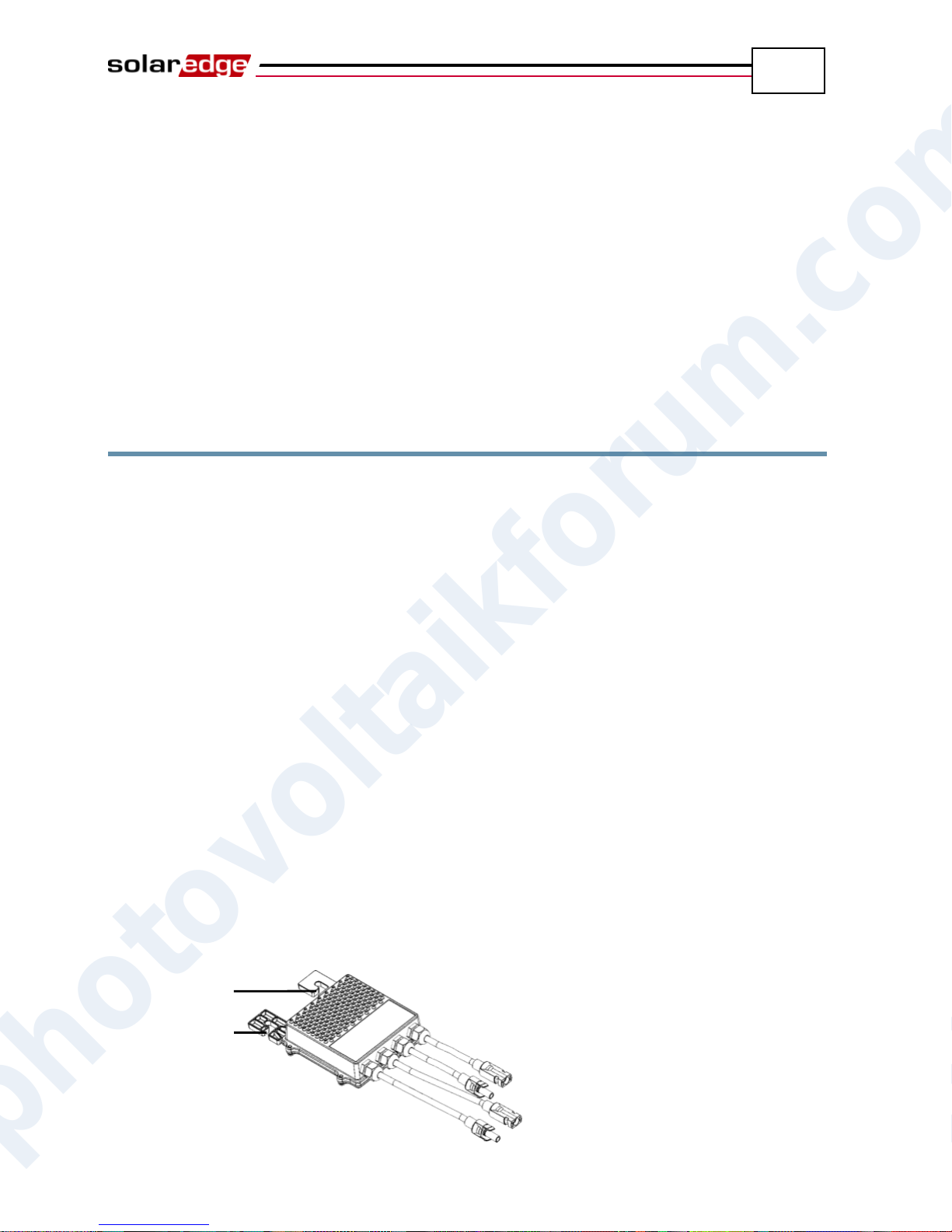
Mounting Hole
Mounting Hole
SolarEdge Installation Guide – MAN-01-00057-2.0
Chapter 1
Introducing the SolarEdge Power
Harvesting System
What is the SolarEdge Power
Harvesting Solution?
The SolarEdge power harvesting solution maximizes the power output from any
type of solar PV installation while reducing the average cost per watt. The
sections below describe each of the system’s components.
SolarEdge Power Optimizer
SolarEdge power optimizers can be connected to existing PV modules in order to
maximize power harvesting by locally performing Maximum Power Point
Tracking (MPPT) at the PV module level.
The power optimizers keep the string voltage fixed, regardless of the length of the
string and of the environmental conditions. Each SolarEdge power optimizer
directly transmits performance data from every PV module over the power line.
Two types of power optimizers are provided by SolarEdge, as follows:
Module add-on solutions, connected during installation to one or more PV
module. P/N: OP250-LV, OP300-MV, OP400-MV and OP400-EV.
Module embedded solution (CSI), is supplied embedded into a PV module.
You may refer to the SolarEdge power optimizer datasheets in order to determine
which power optimizer is most suitable for you requirements.
photovoltaikforum.com
Figure 1: Add-On Box Solution
Page 10
Introducing the SolarEdge Power Harvesting System
10
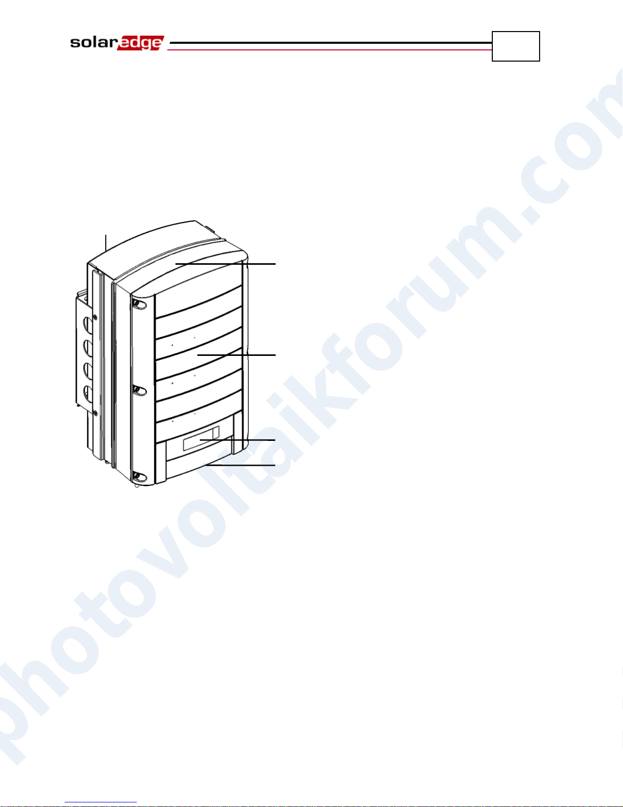
Top
Front
Bottom
LCD
Heat Sink
SolarEdge Installation Guide – MAN-01-00057-2.0
SolarEdge Inverters
The SolarEdge Single Phase and Three Phase Inverters efficiently convert DC
power received from the PV modules into AC power that can be fed into the main
circuit board of the site and from there to the grid. The inverters also receive the
monitoring data from each power optimizer and transmit it to a central server
(called the Monitoring Server) through an Ethernet network to an external modem
connection.
Figure 2: SolarEdge Inverter
Inverter Package Contents
The following lists the contents of the inverter package:
One inverter.
One wall-mounting bracket.
One box containing the following:
Two Allen screws for fastening the inverter to the wall-mounting
bracket.
Installation Guide.
Quick Installation Guide.
Inverter activation instructions.
photovoltaikforum.com
Page 11
Introducing the SolarEdge Power Harvesting System
11
NOTE:
You may refer to the SolarEdge Monitoring Portal User Guide for more information
about this option.
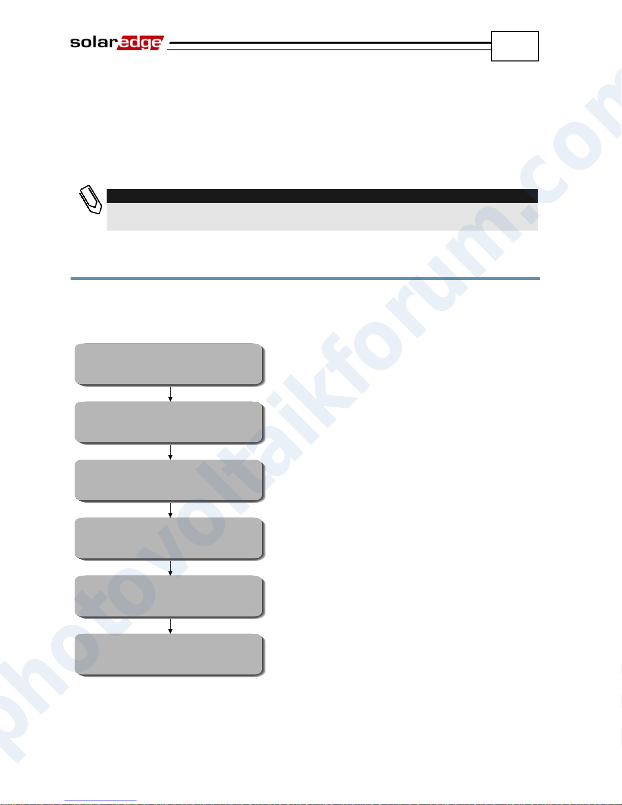
Page 13
Pages 19, 38
Page 21
Page 33
Page 45
Page 66
Installing the Inverter and
Connecting the String to the Inverter
Commissioning and Activating
the Installation
Recording Power Optimizer
Serial Numbers
Connecting the Inverter to the
SolarEdge Monitoring Server
Configuring the Inverter
Connecting Power Optimizers
to Modules and to a String
SolarEdge Installation Guide – MAN-01-00057-2.0
SolarEdge Monitoring Portal
The SolarEdge Monitoring Portal enables you to monitor the technical and
financial performance of one or more SolarEdge Photovoltaic sites. It provides
information about present and past performance of each PV module individually
and about the system as a whole.
Installation Workflow
The following provides an overview of the workflow for installing and setting up
a new SolarEdge site. Most of these procedures can also be used for adding
components to an existing SolarEdge site.
photovoltaikforum.com
Page 12
Introducing the SolarEdge Power Harvesting System
12
SolarEdge Installation Guide – MAN-01-00057-2.0
Transport and Storage
Inverter Transport
The SolarEdge inverter should be transported in its original packaging, facing up
and without exposing the inverter to unnecessary shocks.
Inverter Storage
Store the inverter in a dry place where ambient temperatures are always between
-20°C and +50°C.
Equipment List
Standard tools can be used during the installation of the SolarEdge system. The
following is a recommendation of the equipment to be used when installing a
SolarEdge system:
Allen screwdriver for M6 and M5 screw types.
Drilling machine and bits suitable for a wall or pole, where the inverter
mounting bracket is installed.
Suitable screws for attaching the inverter mounting bracket to a wall.
M6 (1/4”) screws for attaching the power optimizer to the racking.
MC4 crimper
Toolbox, including wire cutters, wire strippers and screwdrivers
Optional: Voltmeter, Electric screwdriver
For installing the communication option, you may also need the following:
For Ethernet: RJ45 connectors
For RS485: A three-wire cable. A four- or six-wire twisted pair telephone
cable may be used.
An inverter has either RJ45/RJ11 connectors or block terminal connectors for
communication. For RJ45/RJ11 connectors, you also require the following:
For Ethernet:
CAT5 twisted pair Ethernet cable
RJ45 crimping tool
For RS485:
photovoltaikforum.com
RJ11 six-pin connector (also known as RJ25)
RJ11 crimping tool
Page 13
Installing the Power Optimizers
13
CAUTION:
If installing directly on the module or module frame, first consult the module
manufacturer for guidance regarding location and the impact on the module warranty.
CAUTION:
SolarEdge power optimizers and inverters use connectors from the following
manufacturers:
Multi Contact MC4
Amphenol H4
Tyco keyed connector
Huber Suhner Raddox
Installing a SolarEdge system without ensuring compatibility of the module connectors
with the optimizer connectors may be unsafe and could cause functionality problems
such as ground faults, resulting in inverter shut down.
In order to ensure mechanical compatibility of the SolarEdge optimizers and the
modules to which they are connected:
Use identical connectors from the same manufacturer and of the same type on
both the power optimizers and on the modules; or
Verify that the connectors are compatible in the following way:
▪ The connector manufacturer should explicitly verify compatibility with the
SolarEdge connector; and
▪ A third-party test report by one of the listed external labs (TUV, VDE, Bureau
Veritas UL, CSA, InterTek) should be obtained, verifying the compatibility of
the connectors.
NOTE:
The power optimizer may be placed in any orientation, meaning there is no up
direction.
NOTE:
The power optimizer should be mounted in a location that is either ventilated or that
has a free space of air around it for heat dissipation.
NOTE:
Mounting brackets are suited to either a flat surface or a pole and can be attached to
any surface texture.
SolarEdge Installation Guide – MAN-01-00057-2.0
Chapter 2
Installing the Power Optimizers
Applicable Notes and Warnings
The following notes and warnings apply when installing the SolarEdge power
optimizers:
photovoltaikforum.com
Page 14
Installing the Power Optimizers
14
IMPORTANT SAFETY FEATURE:
PV modules with SolarEdge power optimizers are safe. They only carry a low safety
voltage before the inverter is turned on.
IMPORTANT SAFETY FEATURE:
As long as the power optimizers are unconnected to the inverter or the inverter is
OFF, the power optimizers will output a safe 1V voltage during installation.
IMPORTANT NOTE:
SolarEdge power optimizers are energized by the PV modules to which they are
connected. String length must not be less than eight power optimizers when using a
single phase inverter and sixteen power optimizers when using a three phase inverte,
or the entire string may shut down. (Please refer to the power optimizer datasheets for
the exact minimum and maximum number of power optimizers permitted in a string.)
NOTE:
Completely shaded PV modules may cause the affected power optimizers to temporarily
shut down. This will not affect the performance of the other power optimizers in the
string, as long as the minimum string length requirement is met when taking into account
the lighted modules only. If under typical conditions modules connected to fewer than
eight optimizers in a single phase system or to fewer than sixteen optimizers in a three
phase system will remain unshaded, add more PV modules.
CAUTION:
Do not drill through the power optimizer or through the mounting holes. The vibrations
created by the drill can damage the power optimizer and will void the warranty.
SolarEdge Installation Guide – MAN-01-00057-2.0
Step 1, Mounting the Power
Optimizers
Determine the mounting location of each power optimizer. The power
optimizer should be mounted in a place where it can be mounted securely
using both mounting holes. It must also be located near enough so that the
power optimizer can connect to a single PV module. Mark all mounting hole
locations.
Each power optimizer must be attached to the rack using both mounting
holes.
Drill the holes.
Mount one power optimizer at each location using M6 (1/4”) screws and
washers.
Verify that the power optimizer is securely attached.
photovoltaikforum.com
Page 15
Installing the Power Optimizers
15
WARNING!
Before performing this step, turn OFF the inverter by turning off the ON/OFF switch at
the bottom of the inverter and the AC switch of the main circuit board. All inverters in
an installation site should be switched OFF in this manner. This step is required to
verify that the power optimizers will output a safe 1V voltage during installation.
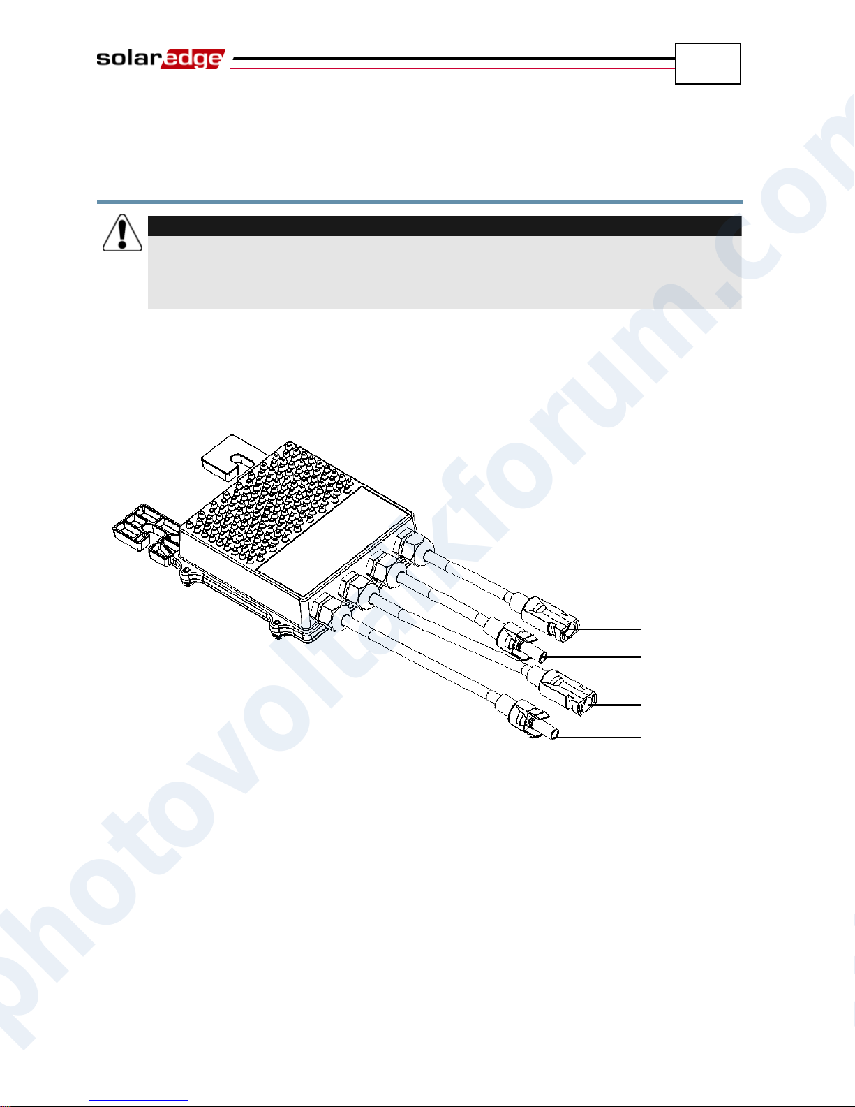
Input +
Input -
Output -
Output +
SolarEdge Installation Guide – MAN-01-00057-2.0
Step 2, Connecting Each PV Module
to a Power Optimizer
OP250-LV, OP300-MV, OP400-MV, OP400-EV
These power optimizers connect to a single PV module via its two inputs (a plus
and a minus).
Figure 3: OP250-LV, OP300-MV, OP400-MV, OP400-EV
photovoltaikforum.com
Page 16
Installing the Power Optimizers
16
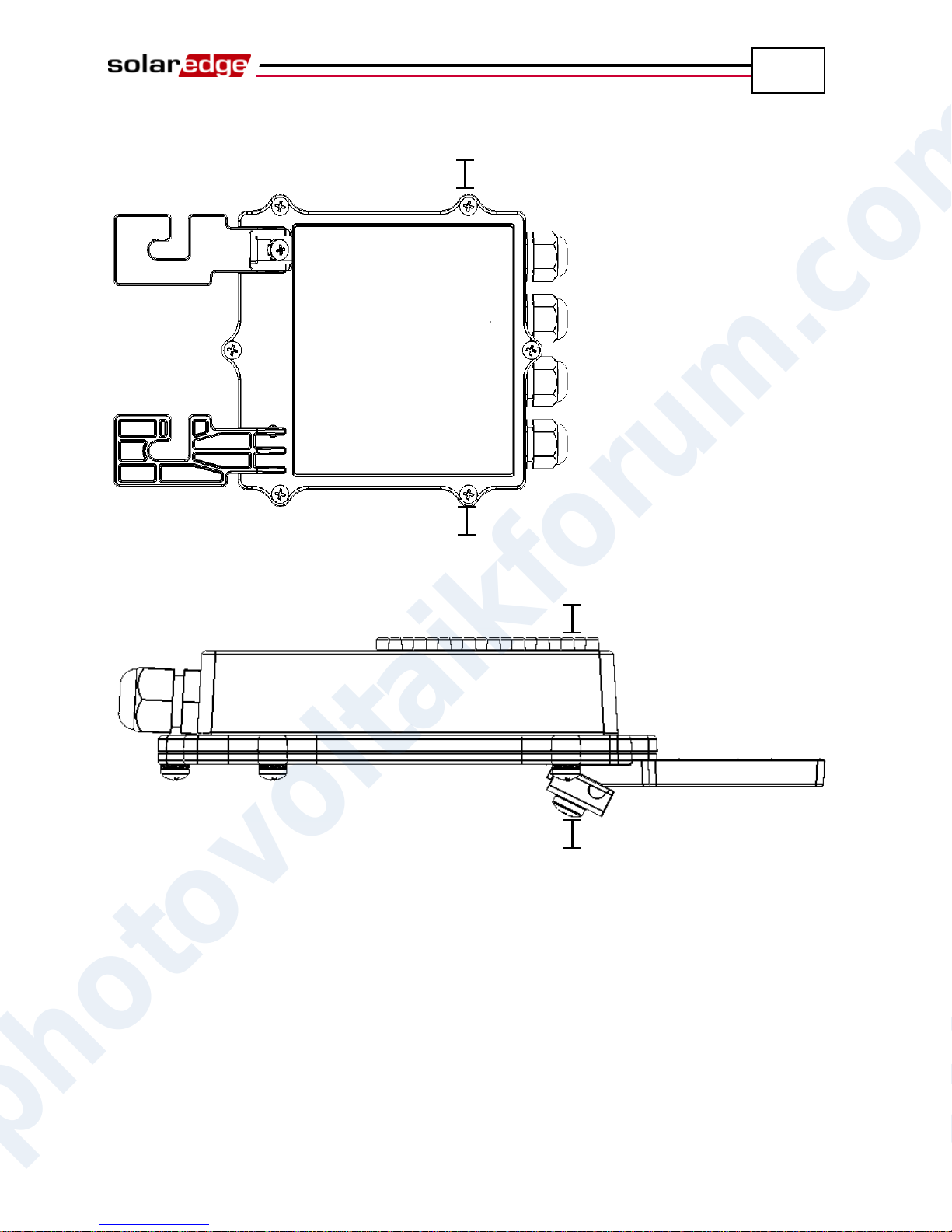
1” (2.5 cm)
1” (2.5 cm)
1” (2.5 cm)
1” (2.5 cm)
SolarEdge Installation Guide – MAN-01-00057-2.0
The following shows the required clearance around the power optimizer.
Figure 4: Clearance – Top View
Figure 5: Clearance – Side View
photovoltaikforum.com
Page 17
Installing the Power Optimizers
17
WARNING!
Verify that you have identified the inputs and outputs correctly. Do not connect PV
modules to power optimizer outputs.
NOTE:
The power optimizer has reverse polarity protection. Even so, you must still verify the
correct polarity by checking the PV module’s polarity with a voltmeter. Some module
manufacturers may use connector polarity that is different from that used by
SolarEdge power optimizer inputs.
IMPORTANT SAFETY FEATURE:
As long as the power optimizers are unconnected to the inverter and the inverter is
OFF, the power optimizers will output a safe 1V voltage during installation.
WARNING!
Make sure that the Plus (+) and the Minus (-) connector cables are firmly and totally
inserted.
IMPORTANT NOTE:
Be sure to record power optimizer serial numbers during their installation, as this
information may be required later for troubleshooting.
The SolarEdge Monitoring Portal can be used to access SolarEdge site information, as
described in the Step 4, Reporting and Monitoring Installation Data section on page 38.
SolarEdge Installation Guide – MAN-01-00057-2.0
Connecting Power Optimizers
► To connect these power optimizers to the PV modules:
The input connectors are shown in the figures above. The output connectors
are in the middle of each side.
Step 3, Connecting Power Optimizers
in Strings
Power optimizers must be connected in series in order to construct strings.
The full string can either be directly connected to the inverter or connected in
parallel to another strings and then together they are connected to the
inverter.
You can construct and connect in parallel strings of unequal length, meaning
the number of power optimizers in each string does not have to be the same.
The power optimizer output cables are labeled + and –.
Connect the Plus (+) connector of the output wire of the first power optimizer
in the string to the Minus (-) connector of the second power optimizer in the
string. Repeat this step for each power optimizer in the string. This procedure
is similar to the standard procedure for connecting PV modules.
photovoltaikforum.com
Page 18
Installing the Power Optimizers
18
SolarEdge Installation Guide – MAN-01-00057-2.0
Verifying Proper Power Optimizer
Connection
► To verify proper power optimizer connection:
Make sure the PV modules are exposed to sunlight during this process.
Otherwise, the power optimizers may not be on.
Verify each string individually before connecting it to the other strings or to
the inverter.
Each power optimizer connected to a PV module initially produces a safe
voltage of 1 V. A string with properly connected power optimizers should
produce 1 V per power optimizer in the string. For example, if 10 power
optimizers are connected in a string, then 10 V should be produced. Use a
voltmeter with at least 0.1V measurement accuracy to verify that the total
voltage produced is in accordance with the number of power optimizers in
the string.
If 0 V is measured for the string, check for a disconnection of the outputs
of one of the power optimizers.
If the voltage is lower than the quantity of power optimizers (for
example, 9 V when 10 power optimizers are connected), verify whether
one or more of the power optimizers are not connected, meaning they
were skipped during the string connection process. If they are all
connected, verify whether one or more of the PV modules is not
connected properly to its power optimizer.
If the voltage is too high, then apply the CAUTION below.
photovoltaikforum.com
Page 19
Installing the Power Optimizers
19
CAUTION:
If the measured voltage is too high, the installation may not have a safe low
voltage. PROCEED WITH CARE!!
Please note that a deviation of up to 2V for a full string is considered
normal.
A voltage that is higher than the quantity of power optimizers may be
caused by one of the following reasons:
An extra power optimizer is connected in the string.
The output of a PV module may be connected in the string instead of the
output of a power optimizer.
A malfunction of one of the power optimizers.
Perform the following if the total string voltage is too high:
Verify that only power optimizers are connected in the string and that no
PV module outputs are connected without a power optimizer.
Disconnect the wires that connect the power optimizers in the string.
Measure that there is 1V safety voltage for each individual power
optimizer in order to locate the power optimizer that does not output the
proper voltage.
If a malfunctioning power optimizer is located, check its connections,
polarity, module and voltage.
If a malfunction cannot be bypassed or resolved, skip the malfunctioning
power optimizer, thus connecting a shorter string.
Do not continue before finding the problem and removing the
malfunctioning power optimizer.
IMPORTANT SAFETY FEATURE:
After a PV module is connected to the power optimizer, the power optimizer
outputs a safe voltage of 1 V. We suggest verifying this output for the first
few power optimizers that you connect in order to verify their proper
connection. Take note that if you use a tracker, the power optimizer will turn
ON only if the tracker is tracking the sun and at least 2 W of power are
provided by the PV module.
SolarEdge Installation Guide – MAN-01-00057-2.0
photovoltaikforum.com
Step 4, Recording Installation
Information
Be sure to record power optimizer serial numbers during their installation, as this
information may be required later for troubleshooting, and is necessary for proper
physical layout on the monitoring website.
The serial number(s) of the inverter(s) must be specified in order to open a new
site.
For more information about recording and monitoring installation data, see
page 38.
Page 20
SolarEdge Installation Guide – MAN-01-00057-2.0
20
Blank page left intentionally
Installing the Power Optimizers
photovoltaikforum.com
Page 21
Installing the Inverter
21
SolarEdge Installation Guide – MAN-01-00057-2.0
Chapter 3
Installing the Inverter
The SolarEdge inverter can be installed either before or after the PV modules and
power optimizers have been installed.
Identifying the Inverter
Refer to the stickers on the side of the inverter that specify its Serial # and its
Electrical Ratings including its Nom Output Power. Please provide the serial
number when contacting the SolarEdge support line. The serial number is also
required when requesting to open a new site in the SolarEdge Monitoring Portal.
Selecting the Mounting Location
This process involves attaching the inverter mounting bracket to a wall or pole
and then mounting the inverter onto it.
Chassis Clearance
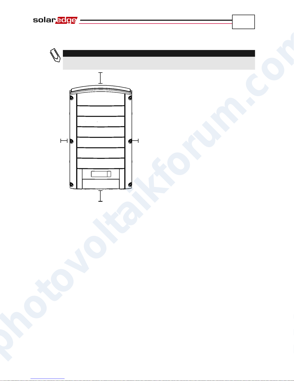
The heat dissipation solution requires the following clearance areas between the
inverter chassis and all types of obstructions, such as wires and walls:
8” (20 cm) to the top and bottom of the chassis
photovoltaikforum.com
Page 22
SolarEdge Installation Guide – MAN-01-00057-2.0
22
NOTE:
If more than one inverter is installed side by side, the distances between them
must exceed 4" (10 cm).
8” (20 cm)
8” (20 cm)
4” (10 cm)
4” (10 cm)
4” (10 cm) to the right and left of the chassis
Installing the Inverter
Figure 6: Chassis Clearance
photovoltaikforum.com
Page 23
Installing the Inverter
23
CAUTION:
Make sure that you have read the previous sections in this chapter before starting the
mounting process that is described below.
SolarEdge Installation Guide – MAN-01-00057-2.0
Mounting the Inverter
The inverter package provides the inverter and the mounting bracket that is
required to connect it to the wall. Standard tools (not provided) can be used
during its installation.
► To mount the SolarEdge inverter:
1 Attach the provided bracket to a wall or pole, as follows:
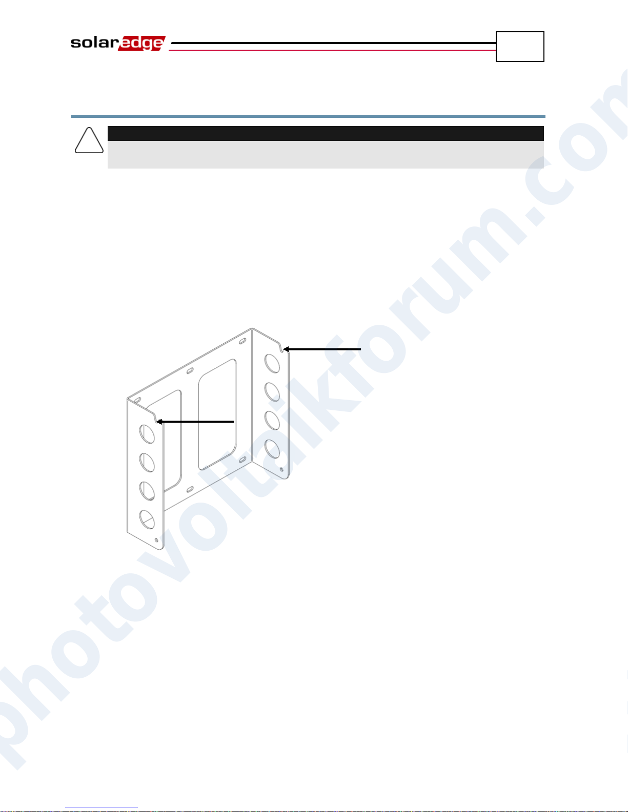
Ensure that the U-shaped part of the bracket is positioned on the top, as
shown below:
Figure 7: Positioning the U-shaped Part of the Bracket
When mounting on a wall, bolt the four outer-most holes of the bracket.
Other holes may be used to stabilize the bracket or when the outer-most
holes cannot be used.
When mounting on a pole, bolt the inner holes of the bracket.
2 Verify that the bracket is firmly attached to the wall or pole.
photovoltaikforum.com
Page 24
Installing the Inverter
24
CAUTION:
Do not rest the connectors at the bottom of the inverter on the ground at any time, as it
may damage them. If you need to rest the chassis on the ground, lay it on its back,
front or side, not on its bottom.
SolarEdge Installation Guide – MAN-01-00057-2.0
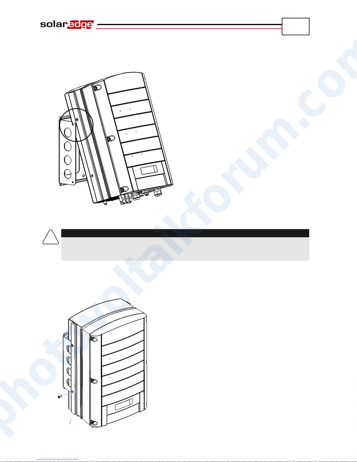
3 Hang the inverter on the bracket using the screws on the inverter’s top, as
shown below:
Figure 8: Hanging the Inverter on the Bracket
4 Let the chassis lay flat against the wall or pole. Then, screw the two Allen
screws into the right and left sides of the bottom of the bracket. The screws
go through the heat sink on either side into the bracket, as shown below:
photovoltaikforum.com
Figure 9: Inserting the Screws through the Bottom of the Heat Sink
Page 25
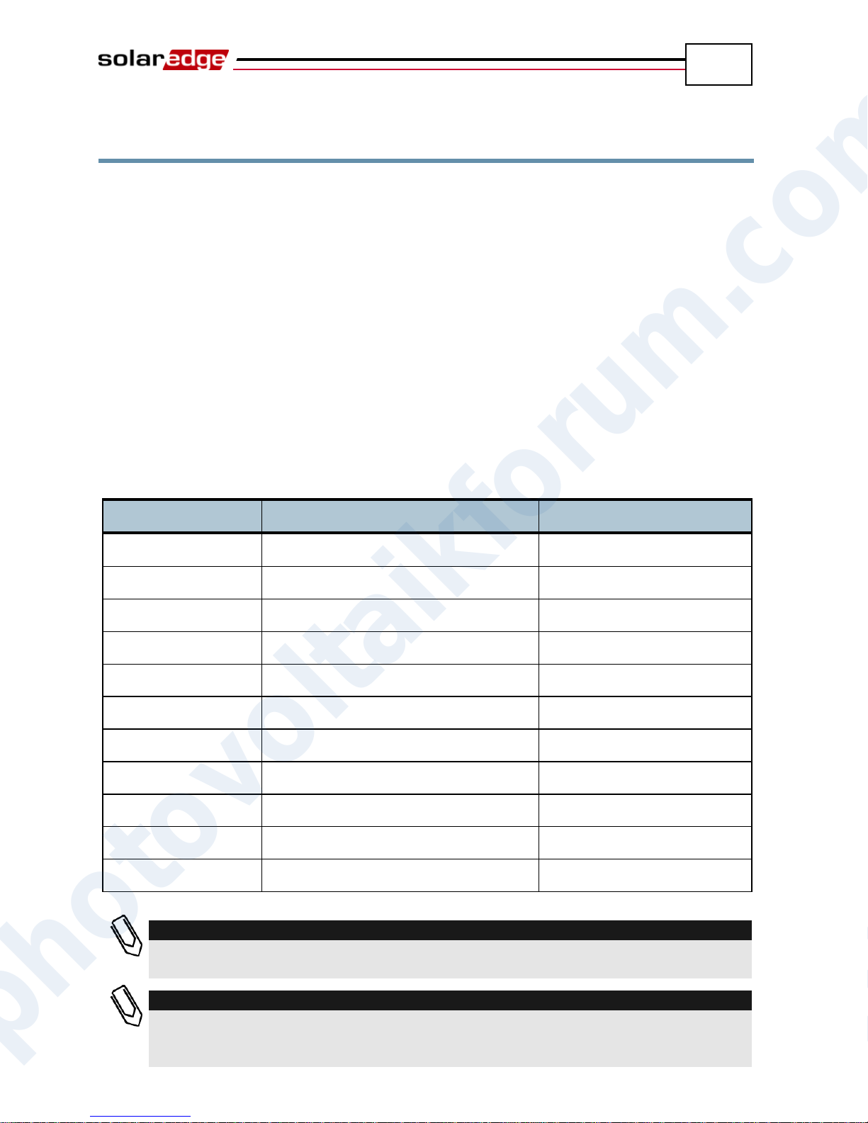
Installing the Inverter
25
Inverter
Maximum Output Current
Suggested Fuse
SE3000
16.5 A
20 A
SE3500
19.5 A
25 A
SE4000
22 A
25 A
SE4000-16A
16 A
20 A
SE5000
27 A
32 A
SE6000
27 A
32 A
SE7k
11.5 A
16 A
SE8k
13.5 A
16 A
SE9k
15.5 A
20 A
SE10k
17.5 A
20 A
SE12.5k
19.5 A
25 A
NOTE
For more wiring information, you may refer to the Application Note called SolarEdge
Recommended AC Wiring, which can be accessed from the SolarEdge website.
NOTE
You should also refer to the technical specifications in Appendix B, Technical
Specifications on page 85. Pay special attention to the inverter specifications because
they may differ slightly in different countries.
SolarEdge Installation Guide – MAN-01-00057-2.0
Connecting the Inverter
Inverter Connection Overview
The SolarEdge inverter can be configured in the field for an AC grid, including
AC voltage and frequency. If the inverter’s default settings are not suited to the
country of the installation site, then please refer to page 72 for a description of
how to configure the inverter for the required country.
With the SolarEdge Configuration Tool, you can configure the inverter’s AC
settings to different settings than those provided by default for the country of the
installation site, or perform other modifications. A full description of the
Configuration Tool is provided in the SolarEdge Configuration Tool Software
Guide.
Refer to the following table to determine the correct fuse size to use at the
connection point of the SolarEdge inverter to the grid:
photovoltaikforum.com
Page 26
Installing the Inverter
26
WARNING!
It is essential to connect the PE (ground) wiring before connecting the AC Line and
Neutral wires.
NOTE
Functional Electrical Earthing of DC-side negative or positive is prohibited because the
SolarEdge inverter has no transformer.
Earthing of PV array module frames and mounting equipment (equipotential bonding)
for the PV array modules is acceptable.
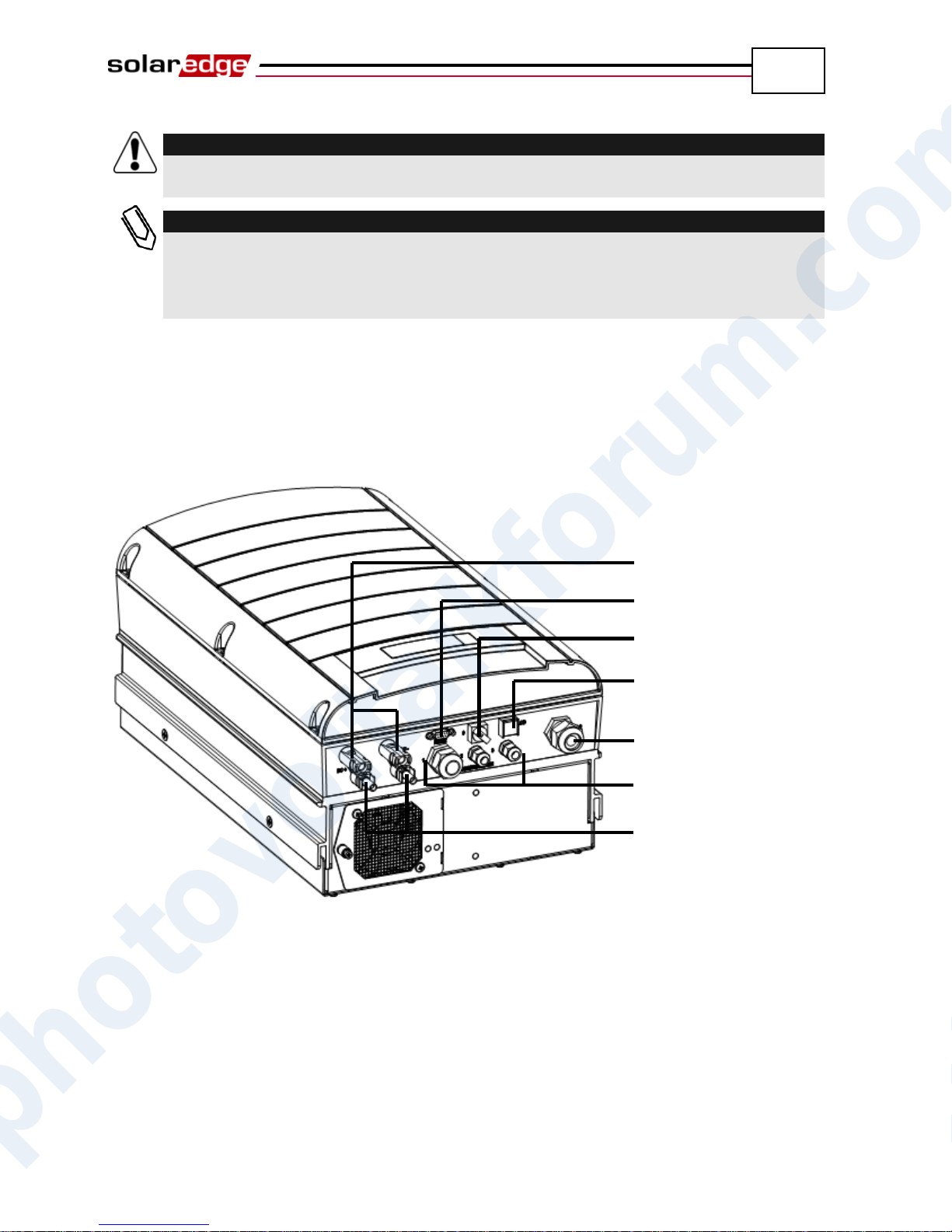
ON/OFF Switch
AC Output
Communication Glands
DC Input Pair
DC Input Pair
LCD Button
RS232
SolarEdge Installation Guide – MAN-01-00057-2.0
Connecting the SolarEdge Inverter
Connectors and Cables
The following shows the inverter connectors:
Figure 10: Inverter Connectors
The following describes each connector, the wire requirements and gauge of its
associated cable. All the inverter connectors are located at the bottom of the
inverter, as described below:
ON/OFF Switch: Turning this switch ON starts the operation of the power
optimizers. Turning it OFF reduces the power optimizer voltage to a low
safety voltage.
photovoltaikforum.com
LCD Button: Pressing this button lights up the LCD for 30 seconds. In
addition, you can press this button to access configuration menu options, as
described on page 74.
Page 27
Installing the Inverter
27
WARNING!
Do not open the cover of the inverter before you turn OFF the ON/OFF switch at
the bottom of the inverter and the DC switch of the main circuit board.
SolarEdge Installation Guide – MAN-01-00057-2.0
RS232 or USB Connector:
Provides a configuration, control and management connection to a
locally connected PC or laptop, or to an external modem (RS232 only)
for connection to the SolarEdge Monitoring Portal. You may refer to the
Creating an RS232 (UART) Connection section on page 47 for a
description of how to set up this communication option to the SolarEdge
Monitoring server.
You may refer to the SolarEdge Monitoring Portal User Guide for more
information about the monitoring capacities.
Other Communication Options (Ethernet (LAN) or ZigBee): Two other
types of communication options can be used to connect the inverter to the
SolarEdge Monitoring Portal. They are installed through the three cable
glands. You may refer to the Chapter 6, Setting Up Communication on page
45 for a description of how to set up these communication options to the
SolarEdge Monitoring server.
AC Output:
AC Cable External Gauge: M25 (11-17mm diameter).
Each of the AC wires (Line, Neutral and PE) must be a copper wire with a
cross-section of 4-16 mm2.
DC Cable: PV connectors.
Connecting the Inverter
Opening the Cover
► To connect AC wires to internal inverter terminals:
1 Turn OFF the AC on the AC wires to be connected to the inverter by
disconnecting the circuit breakers on the main circuit board.
2 Turn off the ON/OFF switch at the bottom of the inverter.
3 Turn off the DC switch on the main circuit board, if one exists.
4 If the inverter was on prior to disconnecting the switch, then wait at least five
minutes before opening the cover of the inverter.
5 Unscrew the Allen screws on the cover of the chassis (on its front) and lift
the cover up.
photovoltaikforum.com
Page 28
Installing the Inverter
28
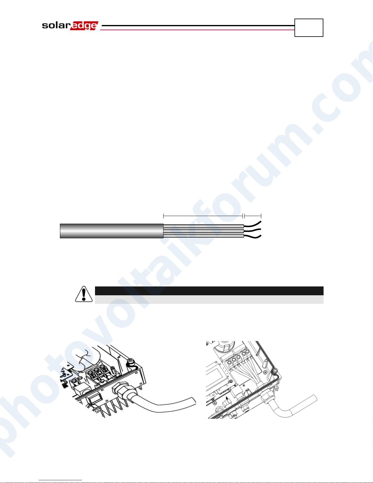
50mm 8mm
WARNING!
Make sure to connect the PE (ground) connector first.
Figure 12: Inserting the Cable
Through the AC Cable Gland –
Single Phase Inverter
Figure 13: Inserting the Cable
Through the AC Cable Gland –
Three Phase Inverter
SolarEdge Installation Guide – MAN-01-00057-2.0
6 Connecting the AC Wires: Strip off the isolation and expose the wires in
the AC cable, as follows:
Single phase inverters – three wires:
Protective Earth (PE) wire
Neutral (N)
Line 1 (L)
Three phase inverters – five wires:
Protective Earth (PE) wire
Neutral (N)
Line 1 (L)
Line 2 (L)
Line 3 (L)
The lengths of the wires to strip are as follows:
Figure 11: Wire Lengths to Strip
Strip 8 mm for contact.
Individual cable length 50 mm.
7 Insert the cable through the AC cable gland on the right and connect the wires
to the appropriate terminal connectors according to their labels: PE, L and N in
the single phase inverter, PE, L1, L2, L3 and N in the three phase inverter.
Figure 12: Inserting the Cable Through the AC Cable Gland – Single Phase Inverter
Figure 13: Inserting the Cable Through the AC Cable Gland – Three Phase Inverter
photovoltaikforum.com
Page 29
Installing the Inverter
29
NOTE:
Due to the SolarEdge architecture, the parallel strings may be of different lengths
and therefore do not necessarily need to be connected to an identical number of
power optimizers.
SolarEdge Installation Guide – MAN-01-00057-2.0
8 Tighten the screws of each wire terminal according to the following torque:
Tightening moment of terminal 0.5-0.6 Nm.
Gland torque 2.8-3.3 Nm.
9 Verify that there are no whiskers in each terminal connector and that the
unused ports of the terminals are sealed.
► To connect DC cables to the inverter:
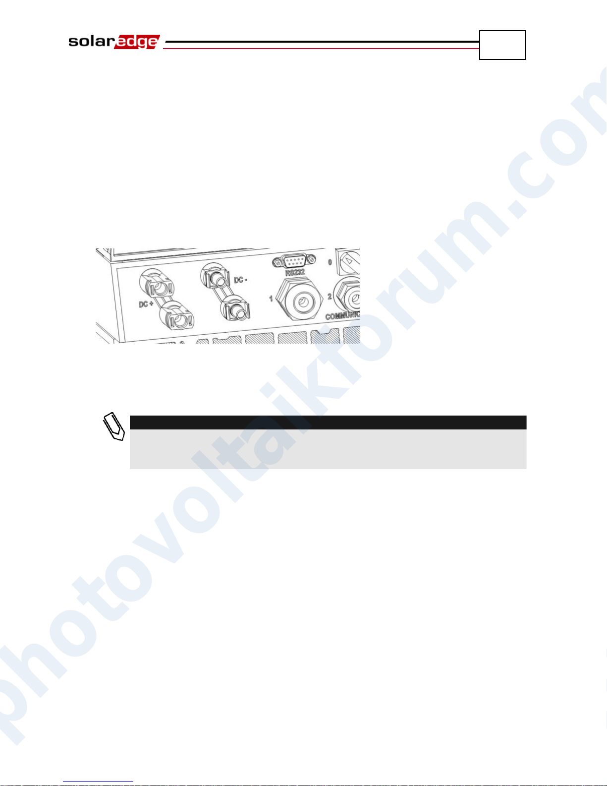
Connect the DC connectors from the photovoltaic installation to the DC+ and
DC- connectors as indicated.
Figure 14: Connecting the DC Cables to the Inverter
If more than two strings are required, they can be connected in parallel in an
external combiner box before connecting a unified DC connection to the inverter.
Completing the Inverter Installation
After completing all connections, the inverter must be activated. Refer to the
activation instructions supplied with the inverter.
In most cases, the inverter is preconfigured before delivery. After activating the
inverter, you must verify that the inverter is configured to the proper country,
as described on page 72.
If not, then you must configure the inverter to the site’s requirements using the
inverter’s internal buttons or by using the SolarEdge Configuration Tool
connected to an RS232 or USB port. For more information, you may refer to the
Configuring the Inverter Using the LCD Panel and User Buttons section on
page 67.
photovoltaikforum.com
Page 30
Installing the Inverter
30
#2
#1
#6
#3
#5
#4
SolarEdge Installation Guide – MAN-01-00057-2.0
If you plan to use the SolarEdge Monitoring Portal to access SolarEdge site
information, you will need to add a physical connection for the proper
communication option. Connecting the inverter to the SolarEdge Monitoring
Server via a LAN, an external modem connected to an RS232 port, or a ZigBee
modem is described in Chapter 6, Setting Up Communication on page 45.
Closing the Cover
► To close the cover:
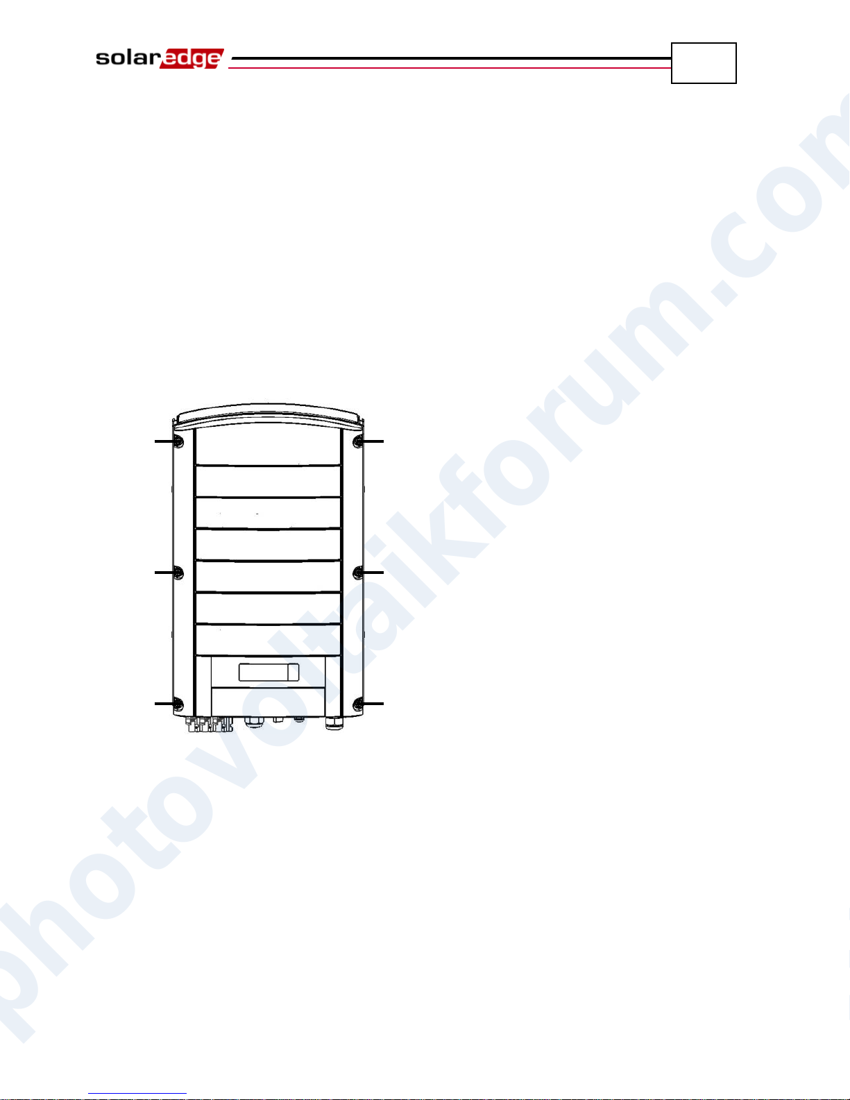
1 Shut the chassis cover and secure it by tightening the screws.
2 For proper sealing, first tighten the corner screws and then the two central
screws. The recommended order can be seen in the following figure:
Figure 15: Tightening the Screws
photovoltaikforum.com
Page 31
Installing the Inverter
31
IMPORTANT SAFETY FEATURE:
All SolarEdge inverters incorporate a certified internal Residual Current Device (RCD)
in order to protect against possible electrocution and fire hazard in case of a
malfunction in the PV array, cables or inverter.
SolarEdge Installation Guide – MAN-01-00057-2.0
Residual Current Device
An external RCD is required in some countries. In these cases, the installer must
check which type of RCD is required by the relevant electric code. SolarEdge
recommends using a type-A RCD. The recommended RCD value is 100mA
or 300mA unless a lower value is required by the specific local electric codes.
When required by local regulations, the use of an RCD type B is permitted.
In installations where the local electric code requires the use of a lower leakage
RCD, the discharge current may trip the RCD. The following steps can be taken
in order to avoid this problem:
1 It is important to select an appropriate RCD in order to ensure proper
operation of the installation. Although the RCD used in such cases is a 30mA
RCD, it may still trip at 15mA (according to IEC 61008). Good quality RCDs
will trip at a higher value.
2 Configure the trip voltage of the inverters’ internal RCD to a lower current
than the trip current of the external RCD. The internal RCD may still trip if
the current is higher than the allowed current, but because the internal
inverter RCD automatically resets when the residual currents are low it does
not require a manual reset. You may consult with the SolarEdge support
center for assistance with this issue.
3 Certain PV modules (with low capacitance leakage to the frame) are
preferable.
Refer to the SolarEdge Application Note RCD Selection for SolarEdge Inverters
for a full discussion of the subject.
photovoltaikforum.com
Page 32
SolarEdge Installation Guide – MAN-01-00057-2.0
32
Blank page left intentionally
Installing the Inverter
photovoltaikforum.com
Page 33
Commissioning the Installation
33
NOTE:
Keep this manual accessible and preferably near the inverter.
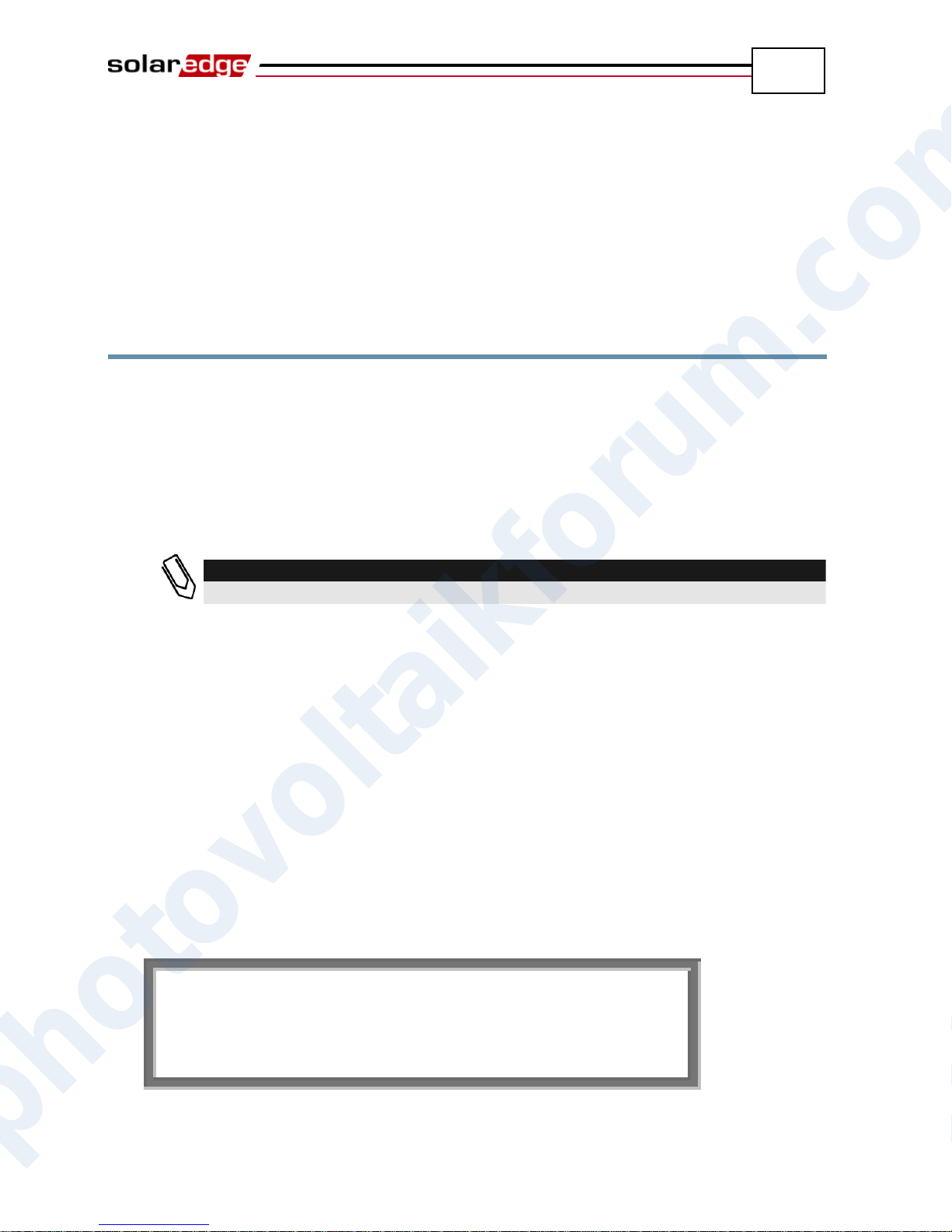
V a c [ v ] V D c [ v ] P a c [ w ] 2 3 0 . 7 1 4 . 1 0 .
0
P _ O K : 0 0 0 / 0 0 0 < S _ O K
>
O F F
SolarEdge Installation Guide – MAN-01-00057-2.0
Chapter 4
Commissioning the Installation
Commissioning – Workflow
The following workflow describes how to activate the system, commission the
installation and verify the proper functioning of the system.
Step 1, Activating the System, page 33
Step 2, Pairing Power Optimizers to the Inverter, page 35
Step 3, Verifying Proper Operation, page 37
Step 4, Reporting and Monitoring Installation Data, page 38
Step 1, Activating the System
This section describes how to perform the initial activation stages of the
SolarEdge system.
These stages are preformed after the inverter and power optimizers have been
installed and the power optimizers have been connected to the inverter.
► To activate the SolarEdge installation:
1 Power OFF the inverter by turning off the ON/OFF switch at the bottom of
the inverter and the DC switch (if exists).
2 Turn on the AC to the inverter. The following message appears on the
inverter’s LCD panel:
photovoltaikforum.com
Page 34
Commissioning the Installation
34
NOTE:
A measurement error on the inverter LCD of ±3 V is OK.
NOTE:
If the LCD panel shows 0 V:
Verify that the PV modules are are not shaded or otherwise obstructed.
Check for proper power optimizer, string and DC input connection.
Verify the correct polarity of the DC input connection.
WARNING!
Verify that the ON/OFF indicator on the LCD panel, described above, reads OFF.
SolarEdge Installation Guide – MAN-01-00057-2.0
3 If the site is installed with an external DC switch between the power
optimizers and the inverter(s), then turn it ON.
4 Verify that P_OK appears, which indicates a connection to the power
optimizers. The number 0 indicates that no power optimizer has been paired
to this inverter. If you are re-pairing the power optimizers and inverters, the
number indicates the number of power optimizers that have been paired in
the past. If P_OK does not appear, check the power optimizer, strings and
DC input connections.
5 If the inverter is connected to the SolarEdge Monitoring server, verify that
S_OK appears. This denotes that the connection to the server is successful.
6 Verify that the Vac [v] on the LCD panel specifies the grid’s correct AC
output voltage, in Volts.
7 Verify that the Vdc [v] on the LCD panel specifies the DC input voltage, in
Volts. There should be a safety voltage of 1 V for each power optimizer
connected to the inverter.
8 Verify that Pac [w] on the LCD Panel specifies 0 as the AC output power, in
Watts. This is because the inverter is still off.
photovoltaikforum.com
Page 35
Commissioning the Installation
35
NOTE:
The power optimizer does not start producing power until it is paired with an inverter.
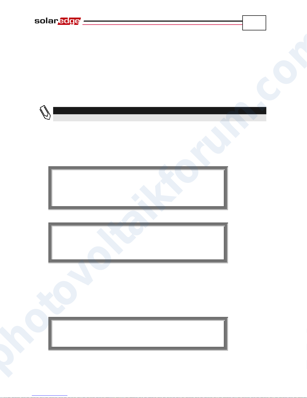
K e e p h o l d i n g b u t t o n f o r p a i r i n g , r e l e a s e t o e n t e r m e n u . . . R e m a i n i n g : 3 s e c
P a i r i n g
T u r n S w i t c h T o o n
P a i r i n g R e m a i n i n g [ S e c ] : 1 0
4
SolarEdge Installation Guide – MAN-01-00057-2.0
Step 2, Pairing Power Optimizers to the
Inverter
After all connections are made, all the power optimizers must be logically paired
to their inverter before they can start working with it. This step describes how to
pair power optimizers to the inverter, meaning to assign each inverter to the
power optimizers from which it will produce power.
► To pair the power optimizers to the inverter:
1 Turn the ON/OFF switch at the bottom of the inverter to OFF. Press and hold
down the inverter’s LCD Light button for about 10 seconds. The following
screen is displayed:
Continue to hold for five seconds more and you will see this screen:
2 Turn the ON/OFF switch at the bottom of the inverter to ON within five
seconds. If you do not turn ON the inverter ON/OFF switch within five
seconds, the inverter then exits pairing mode.
The following screen is then displayed indicating that the inverter is
performing the process of pairing and is assigning power optimizers to the
inverter.
This message displays a countdown of the seconds until it completes the
pairing process. If pairing fails, an error is displayed. This error appears only
photovoltaikforum.com
if the above steps were not followed. If an error appears, then follow the
pairing steps again.
Page 36
Commissioning the Installation
36
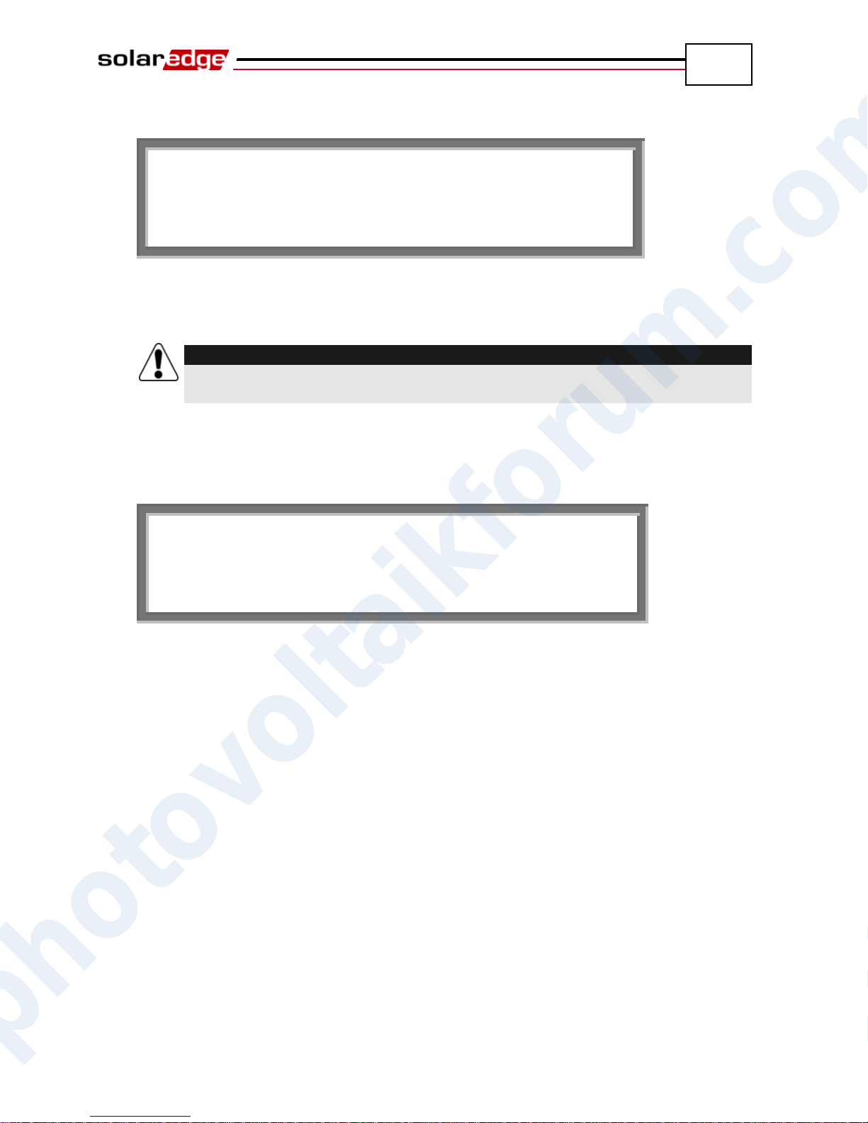
P a i r i n g P a i r i n g C o m p l e t e d
WARNING!
After you turn ON the ON/OFF switch of the inverter, the DC cables carry a high
voltage and the power optimizers no longer output a safe 1 V output.
W a k i n g U P . . .
R e m a i n i n g : 0 5 1 S e c
SolarEdge Installation Guide – MAN-01-00057-2.0
After commissioning succeeds, the following message is displayed:
3 Since at this stage the ON/OFF switch at the bottom of the inverter is ON, the
power optimizers start producing power and the inverter starts converting
AC.
After the initial connection to the AC and before the inverter starts
converting, it will first monitor the grid for the time span required by
regulations (the inverter LED flickers green). While the inverter is in Standby
mode, the following message is displayed:
During this time, the inverter monitors the grid and verifies correct grid
voltage and frequency. This message indicates how many seconds remain
until the inverter will be in Production mode. This amount of time is in
accordance with the regulations of each country, and is typically between
three to five minutes.
The inverter then automatically goes to Production mode and produces power
(the inverter LED is steady green).
photovoltaikforum.com
Page 37
Commissioning the Installation
37
V a c [ v ] V d c [ v ] P a c [ w
]
2 3 0 . 7 3 7 1 . 9 2 3 4 9 .
3
P _ O K : X X X / Y Y Y < S _ O K
>
O N
NOTE:
It can take up to 15 minutes for all power optimizers to transmit their telemetries
and to be counted on the LCD screen.
SolarEdge Installation Guide – MAN-01-00057-2.0
Step 3, Verifying Proper Operation
After the proper wake-up delay time is over, the following message appears on
the inverter’s LCD panel:
► To verify proper operation:
1 Verify that the inverter LED is steady green.
2 Verify that the ON/OFF indicator on the LCD panel, described above, reads ON.
3 Verify that P_OK appears to indicate a connection to the power optimizers.
Also, verify that S_OK appears, if the inverter is connected to the SolarEdge
Monitoring Server.
4 Verify that the total number of power optimizers connected to the inverter
appears next to the P_OK indicator on the LCD panel. If this number is too
low, then it may mean that one or more of the power optimizers are not
connected properly or the pairing process may have not been completely
successful, for example due to complete shading of one of the modules or
insufficient sunlight during the pairing process.
5 Verify that the Vac [v] on the LCD panel specifies the grid’s correct AC
output voltage in Volts.
6 Verify that the Vdc [v] on the LCD panel specifies the DC input voltage in
Volts, which should be between 250 V and 450 V in the single phase inverter
and between 550 V and 950 V in the three phase inverter.
7 Verify that Pac [w] on the LCD Panel specifies the total AC output power
produced, in Watts.
Congratulations! Your SolarEdge power harvesting system is
now operational.
photovoltaikforum.com
Page 38
Commissioning the Installation
38
SolarEdge Installation Guide – MAN-01-00057-2.0
Step 4, Reporting and Monitoring
Installation Data
The SolarEdge Monitoring Portal enables you to access SolarEdge site
information, as described in the SolarEdge Monitoring Portal User Guide, as well
as receive up-to-date information from the installation site for viewing in a
physical or logical view.
After a site is opened in the SolarEdge Monitoring Server, you can access all the
monitored data about that site.
► To register a new site, go to:
http://monitoring.solaredge.com/
The serial number(s) of the inverter(s) must be specified in order to open a new
site.
The SolarEdge Monitoring Server also enables you to display a logical and
physical schematic layout of the installed power optimizers, as follows:
Logical Layout: Shows a schematic logical layout of the components in the
fields, meaning inverters, clusters, strings and modules and their electrical
connectivity. This view enables you to see a logical view of which modules
are connected in each string, which strings are connected to each inverter and
so on.
Physical Layout: Shows a schematic physical layout of the components in
the fields, meaning inverters, clusters, strings and modules and their electrical
connectivity. This view enables you to see a physical bird’s eye view of the
installation site showing which modules are connected in each string, which
strings are connected to each inverter and so on.
This window enables you to:
View the latest performance of specific components.
Find underperforming components, such as modules, by comparing their
performance to that of other components of the same type.
Pinpoint the location of alerted components.
See how components are connected to each other.
In order to enable the SolarEdge Monitoring Portal to show the strings and the
physical location of power optimizers, you may first supply the physical and
logical mapping of the installed power optimizers.
photovoltaikforum.com
Page 39
Commissioning the Installation
39
IMPORTANT NOTE:
Even if you do not report the physical and logical mapping of the installed power
optimizers to SolarEdge, the SolarEdge Monitoring Portal will still show the logical
layout indicating which power optimizers are connected to which inverters. However, it
will not show strings or the physical location of power optimizers.
IMPORTANT NOTE:
Be sure to record power optimizer serial numbers during their installation, as this
information may be required later for troubleshooting.
SolarEdge Installation Guide – MAN-01-00057-2.0
This process prepares the SolarEdge Monitoring Portal for receiving
up-to-date information from the installation site and for displaying it in a physical
or logical view.
The inverter may be connected to the SolarEdge Monitoring Server via a LAN or
an external SolarEdge GSM modem connected to the RS232 port. Alternatively,
you can connect the inverter to another inverter that is already connected to the
server.
The inverter-to-inverter connection is made by an RS485 bus or a ZigBee modem.
This connection enables the inverters to send the latest data collected from the
power optimizers and inverters to the SolarEdge Monitoring Server.
If the inverter is properly connected to the internet, as described in the Step 3,
Verifying Proper Operation section on page 37, then the S_OK appears in the
inverter’s LCD screen.
Providing Installation Information
iPhone Site Mapper
SolarEdge provides an iPhone Site Mapper that helps you collect information
about your installation. This application leads you through the process of
scanning the labels on each inverter and power optimizer. It then helps you
transmit this collected information to SolarEdge’s Monitoring Portal (which was
described on the previous pages). The SolarEdge iPhone Mapping Application
can be downloaded from the SolarEdge website.
photovoltaikforum.com
Page 40
SolarEdge Installation Guide – MAN-01-00057-2.0
40
Blank page left intentionally
Commissioning the Installation
photovoltaikforum.com
Page 41
Replacing and Adding System Components
41
D C V O L T A G E N O T S A F E
!
D O N O T D I S C O N N E C T !
V D C : 7 2 . 0
WARNING!
Do not touch the DC power connections until the DC voltage is at a safe level.
Doing so may cause personal damage, damage to the device and/or danger of
fire.
WARNING!
If you cannot see the inverter panel, or there is a malfunction indicated on the
LCD panel, then switch off the AC to the inverter and wait five minutes for the
input capacity of the inverter to discharge.
SolarEdge Installation Guide – MAN-01-00057-2.0
Chapter 5
Replacing and Adding System
Components
Modifying an Existing Installation
This section describes how to modify an existing installation that has been
operating properly for a while.
► To modify an existing installation:
1 Shut down the inverter by turning OFF its ON/OFF switch and the DC switch
of the main circuit board. The inverter goes into Shutdown mode and
displays the following message:
This message is displayed until the DC is safe. The default safety voltage is
50 V.
2 Switch off the AC to the inverter.
3 You can now add or remove power optimizers, add or remove strings, change
connections of power optimizers or strings or replace the inverter.
photovoltaikforum.com
Page 42
Replacing and Adding System Components
42
NOTE:
If you are permanantly dismantaling the installation or part of it, make sure to use
the disposal method dictated by the regulations of the country in which the
inverters are installed.
CAUTION:
Commissioning must first be performed on the inverter to which power optimizers
were added, and only then on the inverter from which power optimizers were
removed. Otherwise, the inverter to which power optimizers were added may be
damaged.
SolarEdge Installation Guide – MAN-01-00057-2.0
4 Perform the Commissioning – Workflow, as described on page 33.
► To move one or more power optimizers from one inverter
to another in the same site:
1 Turn both inverters OFF, as described above.
2 Remove the necessary power optimizers from their inverter and connect them
to the strings of the other inverter.
3 Perform the Commissioning – Workflow, as described on page 33, on the
inverter to which power optimizers were added and only then perform the
Commissioning – Workflow on the inverter from which power optimizers
were removed.
photovoltaikforum.com
Page 43
Replacing and Adding System Components
43
SolarEdge Installation Guide – MAN-01-00057-2.0
Three Phase Inverters – Replacing
the Fans
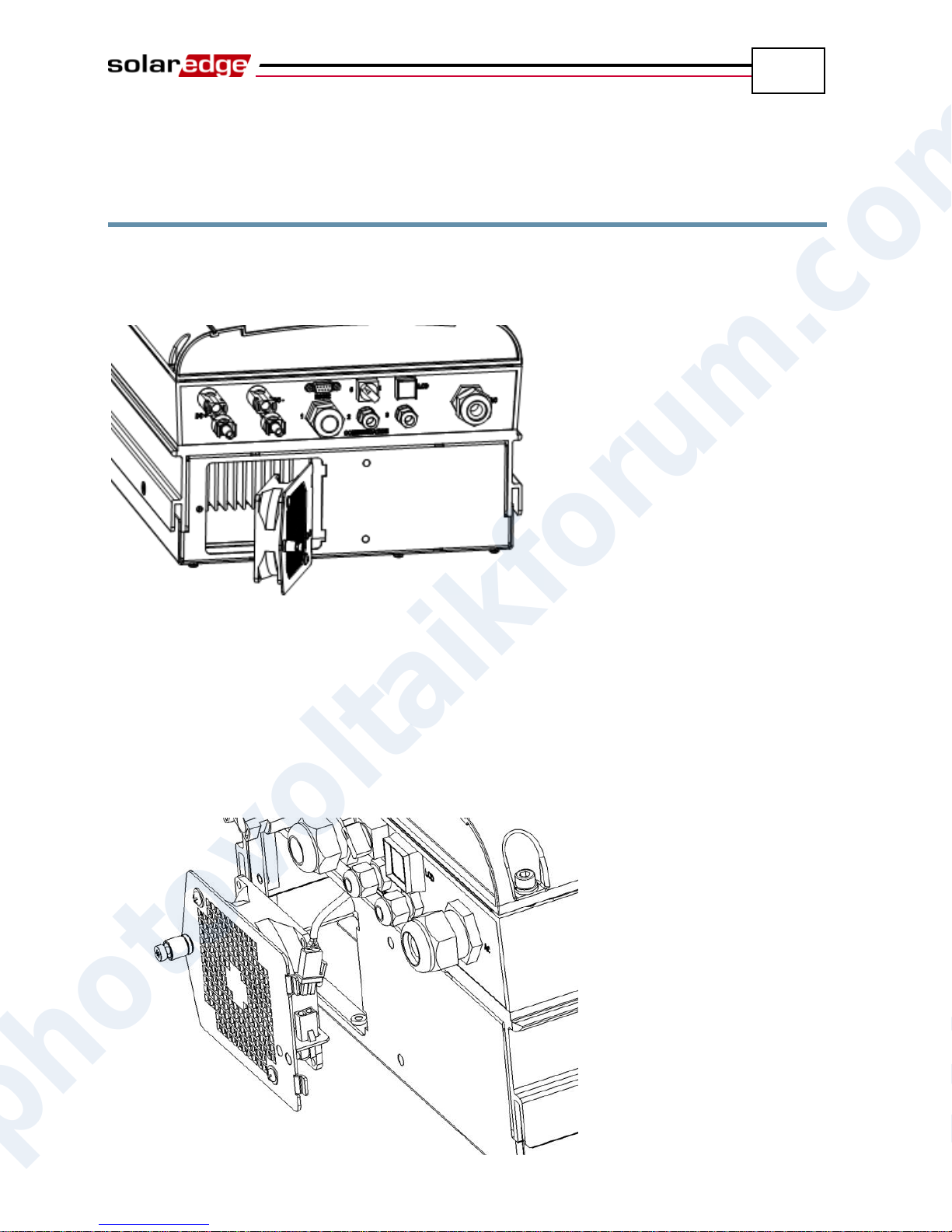
The three phase inverter has two fans, one is accessible from the outside of the
inverter (called Fan 1) and the other is internal and requires a SolarEdge
technician to replace it (called Fan 2).
Figure 16: Inverter Fan 1
► To replace Fan 1:
1 Unscrew the single screw of the fan cover, shown above, using a Philips
screw driver.
2 Open the fan door.
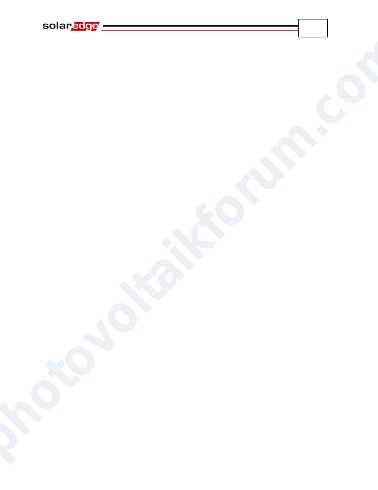
3 Disconnect the fan door connector, as shown below:
photovoltaikforum.com
Figure 17: Fan Door Connector
Page 44
Replacing and Adding System Components
44
SolarEdge Installation Guide – MAN-01-00057-2.0
4 Unscrew the two screws connecting the fan to the cover.
5 Replace the fan unit with the new one and screw it using the two screws.
6 Connect the fan door connector.
7 Check the Fan Health Status screen to make sure that the fan was installed
properly, as described in the Fan Health Status Window – Three Phase
Inverters section on page 66.
photovoltaikforum.com
Page 45
Setting Up Communication
45
Gland
Size (in mm)
Function
Wire Size
1
20
Ethernet connection (CAT5/6) or ZigBee antenna
4.5 – 7 mm
2 + 3
16
RS485, ZigBee antenna, phase balancer, power reducer
2 – 7 mm
Communication Glands
DC Input
Pairs
AC Output
RS232
Connector
On/Off
Switch
LED
Button
SolarEdge Installation Guide – MAN-01-00057-2.0
Chapter 6
Setting Up Communication
Communication Dataflow
The SolarEdge site information can be accessed remotely using the SolarEdge
Monitoring Portal, as described in the SolarEdge Monitoring Portal User Guide.
In order to transfer monitoring data from a SolarEdge site to the SolarEdge
Monitoring Portal, a communication connection must be set up, as described in
this chapter. Communication setup is not required for power harvesting and is
needed only when using the monitoring portal.
Power optimizers send information to the SolarEdge inverter via DC lines. No
added wires or configurations are required for this purpose. The inverter sends
this information to the SolarEdge Monitoring Server through the Internet. The
sections below describe how to set up this connection.
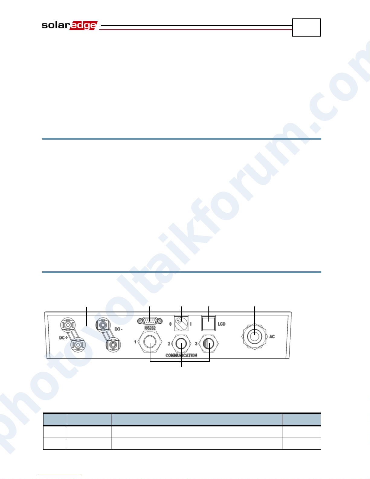
Connector Panel
The connector panel on the inverter appears as shown below:
Figure 18: Connector Panel
Each communication gland on the panel is numbered, as described in the
following table.
photovoltaikforum.com
Be sure that the communication type in use connects to the appropriate gland.
Page 46
Setting Up Communication
46
NOTE:
In addition, there are two types of wireless communication options that are
available and purchased separately. They are: ZigBee and GSM. Refer to
relevant documentation for details about their installation.
Ethernet
RS485 (RJ11)
RS232
SolarEdge Installation Guide – MAN-01-00057-2.0
Communication Types
The following types of communication can be used to transfer the monitored
information from the inverter to the SolarEdge Monitoring Server:
RS232 (UART): page 47, This communication option is provided in all
inverters by default. It is used to connect to an external SolarEdge GSM
modem that has an RS232 port.
Ethernet: page 49, Enables the connection of the inverter directly to a LAN.
RS485: page 54, Enables the connection of multiple inverters through the
same bus, such that connecting only one inverter to the Internet is sufficient
to provide communication services to all the inverters on the bus.
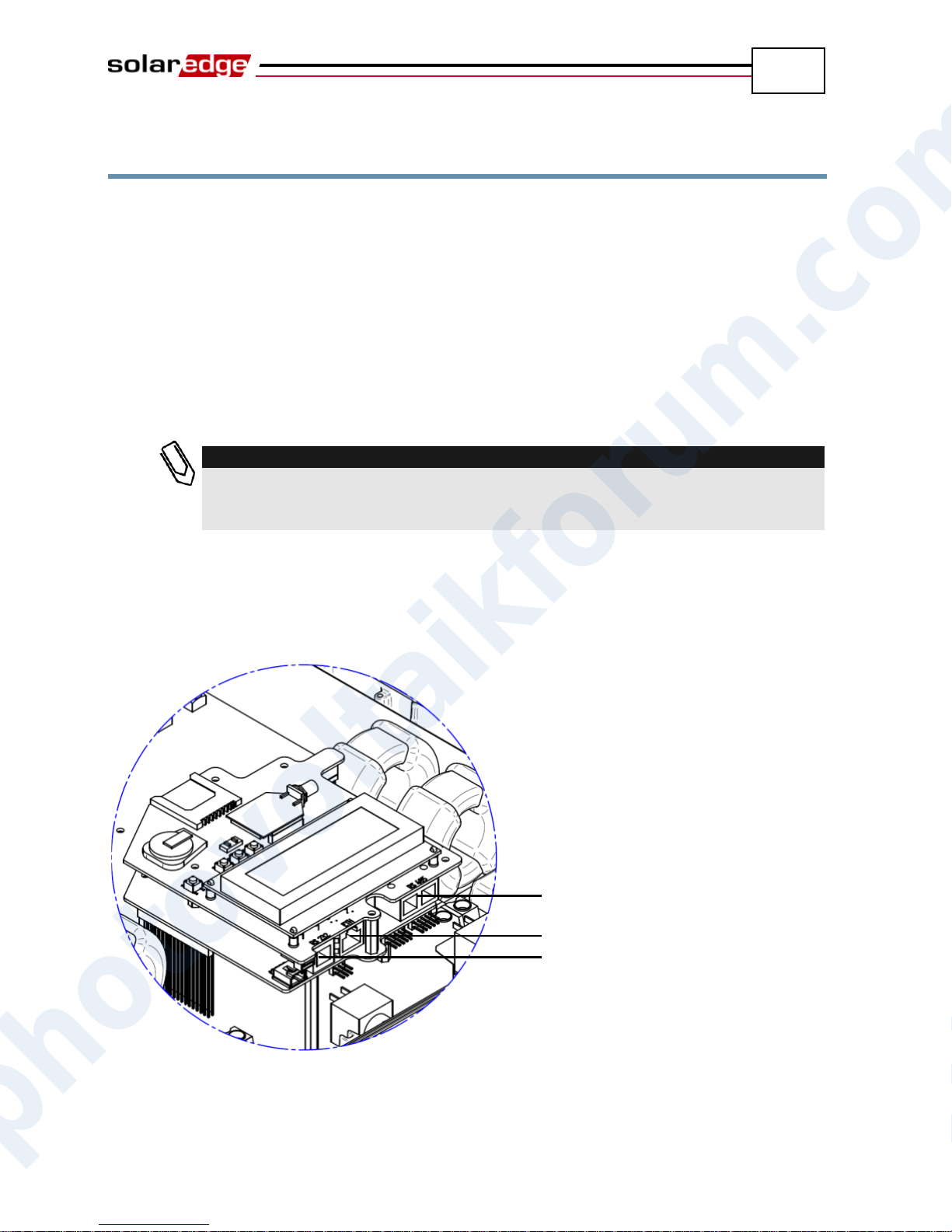
Ethernet and RS485 are connected to a connector inside the inverter. An inverter
communication board has either RJ45/RJ11 connectors or block terminal
connectors for communication.
The following shows the location of the RJ45/RJ11 communication connectors:
Figure 19: Ethernet and RS485 – RJ45/RJ11 Connectors
photovoltaikforum.com
Page 47
Setting Up Communication
47
NOTE:
When connecting via RS232, make sure to use a shielded connector so as not to
interfere with other devices in the vicinity.
RS232 Connector
RS485-1 (B, A G from left to right)
Ethernet (8)
RS485-2 (Not Used)
RS232 / Phase Balancer
Power Reducer
SolarEdge Installation Guide – MAN-01-00057-2.0
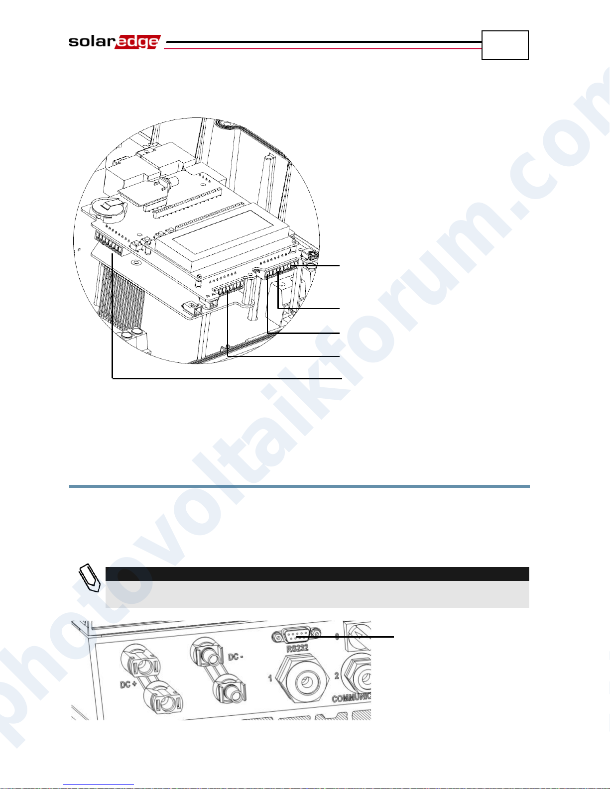
The following shows the location of the block terminal communication
connectors:
Figure 20: Block Terminal Connectors
Creating an RS232 (UART)
Connection
This communication option is provided in all inverters by default. It enables you
to connect the inverter via modems supplied by SolarEdge. You may refer to the
SolarEdge website for a list of the types of modems offered. Each modem is
provided with its own user manual which should be reviewed.
photovoltaikforum.com
Figure 21: RS232 Connector
Page 48
Setting Up Communication
48
IMPORTANT SAFETY FEATURE:
The RS232 conector on the bottom of the inverter is safe to touch during normal
operation of the inverter
SolarEdge Installation Guide – MAN-01-00057-2.0
► To configure RS232 communication to the SolarEdge
Monitoring Server:
1 Using the user buttons, select the RS232 option under the Communication
Server menu, as described in the Configuring the Inverter Using the LCD
Panel and User Buttons section on page 67.
2 Follow the instructions of your SolarEdge modem for model-specific
configuration options.
3 Connect the modem to the inverter through the RS232 connector, which is
the nine-pin connector on the bottom of the inverter. There is no need to open
the inverter cover.
To verify the connection, you may refer to the Verifying the Connection section
on page 59.
The internal RS232 terminal block connector located on the communication
board, shown in Figure 20, can also be used for phase balancing. You may refer
to the SolarEdge Phase Balancing User Guide for more details.
photovoltaikforum.com
Page 49
Setting Up Communication
49
SolarEdge Inverter
Router/Hub
ZigBee RS485 RS232 Ethernet
Single Inverter Connected Multiple Inverters Connected
SolarEdge Inverter
ZigBee RS485 RS232 Ethernet
SolarEdge Inverter
ZigBee RS485 RS232 Ethernet
SolarEdge Inverter
ZigBee RS485 RS232 Ethernet
Router/Hub
SolarEdge Installation Guide – MAN-01-00057-2.0
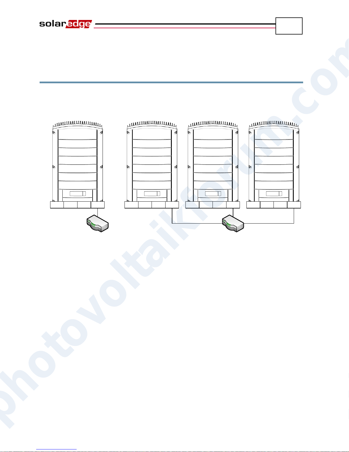
Creating an Ethernet (LAN)
Connection
This communication option enables you to use an Ethernet connection to connect
the inverter to a LAN.
Figure 22: Example of Ethernet Connection
► To connect the Ethernet communication to the
SolarEdge Monitoring server:
1 Open the cover of the inverter, as described in the Opening the Cover section
photovoltaikforum.com
on page 27.
2 Using the user buttons, choose the LAN option under the Communication
Server menu , as described in the Configuring the Inverter Using the
LCD Panel and User Buttons section on page 67.
3 Configure the LAN options under the Communication menu (DHCP and IP
configurations), as described in the Configuring the Inverter Using the LCD
Panel and User Buttons section on page 67.
4 Prepare to connect the Ethernet cable to the Ethernet connector on board in
the inverter, as follows:
Insert the Ethernet wire via the large cable gland on the bottom of the
inverter. The inverter glands come pre-sealed from the factory.
Removing the sealing is needed to insert the cable.
Page 50
Setting Up Communication
50
CAUTION:
If a gland is opened and not used, then make sure to reseal it. Otherwise, it
may affect the inverter’s functionality.
CAUTION:
The internal side of the gland includes an o-ring, which should be used to
ensure proper sealing.
NOTE:
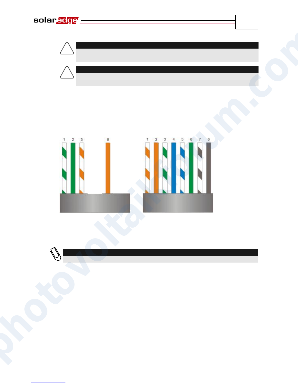
One to eight wires can be connected. Only 1, 2, 3 and 6 are mandatory.
SolarEdge Installation Guide – MAN-01-00057-2.0
Remove the cable’s external isolation using the crimping tool or cable
cutter and expose 8 wires. Standard cables have 8 wires (4 twisted pairs),
as shown in the diagram below, on the right. For Ethernet
communication, 4 wires (2 twisted pairs) are used, as shown in the
diagram below, on the left. Wire colors may differ from one cable to the
next.
Figure 23: Preparing Connector Wiring
Only wires numbered 1, 2, 3 and 6 in the diagram on the left above need to
be connected.
photovoltaikforum.com
Page 51
Setting Up Communication
51
SolarEdge Installation Guide – MAN-01-00057-2.0
5 An inverter has either RJ45/RJ11 connectors or block terminal connectors for
communication.
If the inverter has RJ45/RJ11 communication connectors, then connect as
follows:
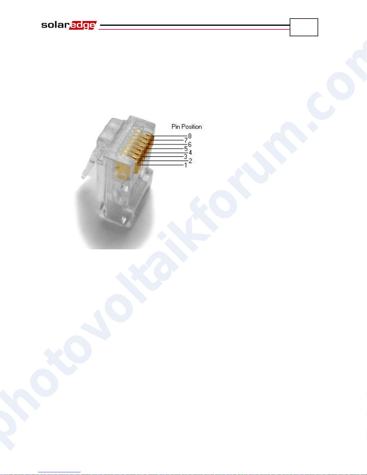
Insert the 4 wires into the RJ45 connector. Make sure to use pins 1, 2, 3
and 6.
Figure 24: Inserting Wires into the RJ45 Connector
Use the Ethernet crimper to crimp the wires.
Connect the Ethernet connector to the RJ45 plug on the board in the
inverter, as shown in Figure 19.
photovoltaikforum.com
Page 52
Setting Up Communication
52
NOTE:
Wires 1-7 may be connected. Only 1, 2, 3, 6 and S are mandatory.
6
Screws
G S 7 3 2 4 1
Connect Only These
SolarEdge Installation Guide – MAN-01-00057-2.0
If the inverter has block terminal communication connectors, then connect as
follows:
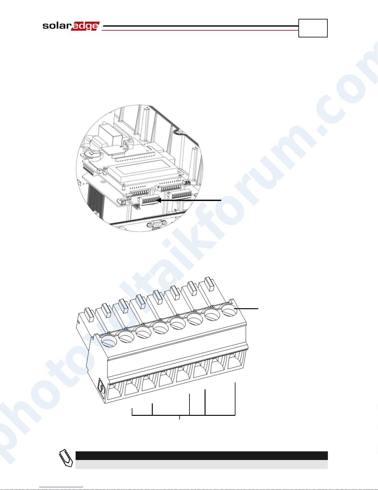
The Ethernet block terminal is already inserted into the inverter when it
is delivered. Pull out the Ethernet block terminal, as shown on the left
below:
Figure 25: Removing the Ethernet Block Terminal
Loosen the screws of connectors 1, 2, 3, 6 and S on the Ethernet block
terminal, as shown below:
Figure 26: Ethernet Block Terminal
photovoltaikforum.com
Page 53
Setting Up Communication
53
NOTE:
Make sure to push in the Ethernet block terminal firmly so that it is inserted
as far in as it goes.
NOTE:
If your network has a firewall, then you may need to configure it to enable the
connection to the following address:
Destination Address: prod.solaredge.com
Port: 22222
SolarEdge Installation Guide – MAN-01-00057-2.0
Insert the ends of wires 1, 2, 3 and 6 into the connectors shown above.
Insert the aluminum shield of the cable into the S connector.
Close the screws of the Ethernet block terminal.
Reinsert the Ethernet block terminal into the communication board. The
Ethernet block terminal can only be inserted with the screws facing the
wall (towards the inverter heat-sink).
6 Connect the other end of the Ethernet cable to the Ethernet plug of the
Ethernet hub or router. You can connect more than one inverter to the same
hub or to different hubs, as required. Each inverter sends its monitored data
independently to the SolarEdge Monitoring server. All connections are
initiated from the inverter so that no port forwarding is required.
7 Close the inverter cover, as described in the Closing the Cover section on
page 30.
8 Verify the connection, as described in the Verifying the Connection section
on page 59.
photovoltaikforum.com
Page 54
Setting Up Communication
54
SolarEdge Installation Guide – MAN-01-00057-2.0
Creating an RS485 Bus Connection
The RS485 option enables you to create a bus of connected inverters. Using this
option, inverters are connected to each other in a chain, meaning the first inverter
in the chain is connected to the next inverter in the chain via its RS485 connector.
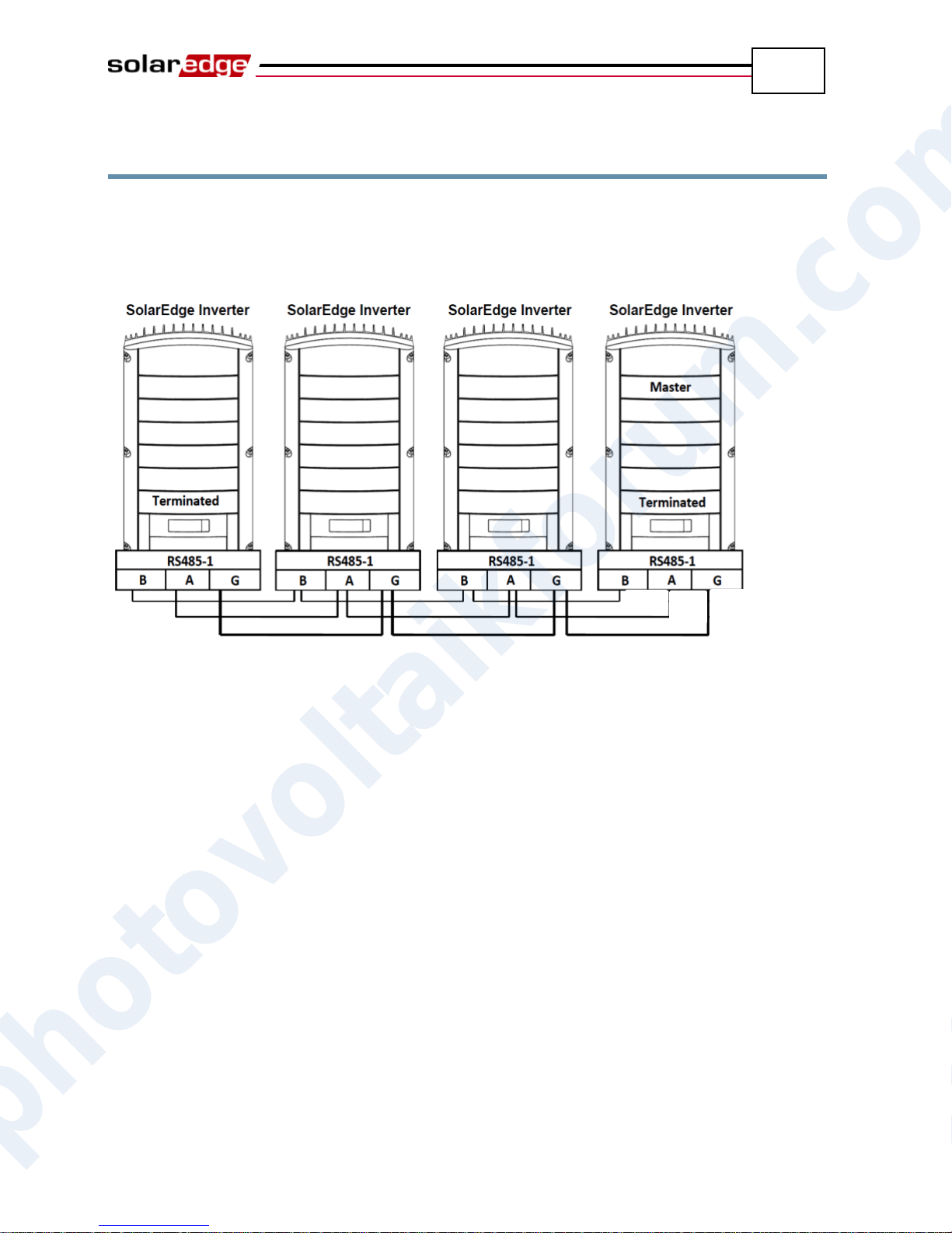
The first inverter in the chain and the last inverter in the chain must be terminated.
Figure 27: Example of RS485 Bus Connection
Each inverter must be connected according to the instructions below.
► To connect the RS485 communication bus:
1 Open the cover of the inverter, as described in the Opening the Cover section
on page 27.
2 Using the user buttons, select the RS485 option under the Communication
Bus menu, as described in the Configuring the Inverter Using the LCD
Panel and User Buttons section on page 67.
3 For all slave devices, using the user buttons, select the RS485 option under
the Communication Server menu, as described in the Configuring the
Inverter Using the LCD Panel and User Buttons section on page 67.
photovoltaikforum.com
Page 55
Setting Up Communication
55
CAUTION:
If a gland is opened and not used, be sure to reseal it. Otherwise, it may
affect the inverter’s functionality.
SolarEdge Installation Guide – MAN-01-00057-2.0
4 An inverter has either RJ45/RJ11 connectors or block terminal connectors for
communication.
If the inverter has RJ45/RJ11 communication connectors, then connect as
follows:
The RS485 bus uses a three-wire cable and a six-wire RJ11 connecter
(also known as RJ25). Insert the wire via one of the small cable glands.
The glands come from the factory pre sealed. Removal of the sealing is
required in order to insert the cable.
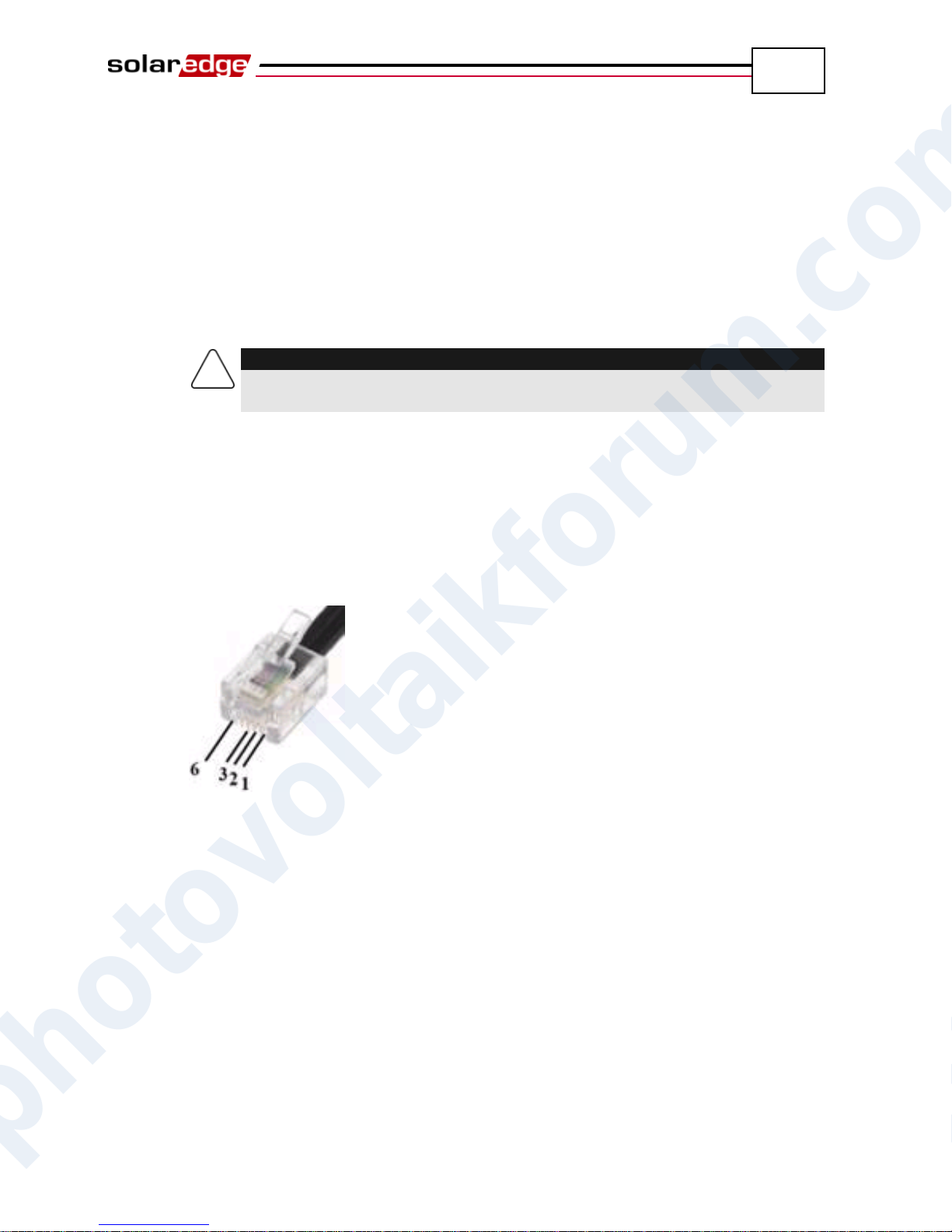
After inserting the wire, crimp a connector using a standard telephone
wire crimper. Two pins (numbered 2 and 3) must be connected. The two
wires must both belong to the same twisted pair, which is usually
indicated by similarly colored wire. In addition, a grounding wire that is
connected to pin number 6 must also be connected. For this purpose, you
can use any remaining wire of the telephone cable. The wiring on the
next inverter should be the same.
Figure 28: Crimping the Wires
Connect the RS485 cable connector to either of the RS485 plugs on
boards in the inverter.
Connect the other end of the RS485 cable of the first inverter through the
gland to the RS485 connector on the board of the next inverter in the
chain, as described above.
You can use both RS485 connectors to wire up to two inverters – one to
the left and one to the right
photovoltaikforum.com
Page 56
Setting Up Communication
56
CAUTION:
Do not insert wires into the connectors labeled RS485-2
G
A
B
SolarEdge Installation Guide – MAN-01-00057-2.0
If the inverter has block terminal connectors, then connect as follows:
The RS485/RS232 block terminal is already inserted into the inverter
when it is delivered. Pull out the block terminal, as shown on the left
below:
Figure 29: Removing the RS485/RS232 Block Terminal
Loosen the screws of each of the connectors B, A and G on RS-485-1.
Figure 30: RS485/RS232 Block Terminal
photovoltaikforum.com
The RS485 bus uses a three-wire cable. Insert the cable via one of the
small cable glands.
Page 57
Setting Up Communication
57
NOTE:
Make sure to push in the RS485 block terminal firmly so that it is inserted as far in
as it goes.
Use the left switch
SolarEdge Installation Guide – MAN-01-00057-2.0
Connect wires into the B, A and G terminals on RS-485-1.
All B wires on all inverters should be connected.
All A wires on all inverters should be connected.
All G wires on all inverters should be connected.
Do not cross-connect B, A and G wires Do not insert wires into the
connectors labeled RS485-2.
Connect the other inverters in the chain. You can use any color wire to
connect between each connector A on one inverter to connector A on the
other inverter, as long as you use the same color wire for all A
connectors. The same goes for connecting between G connectors and for
connecting between B connectors. Figure 27 conceptually depicts this
connection schema.
Reinsert the block terminal into the communication board.
The RS485 block terminal can only be inserted with the screws facing
the wall (towards the inverter heat-sink).
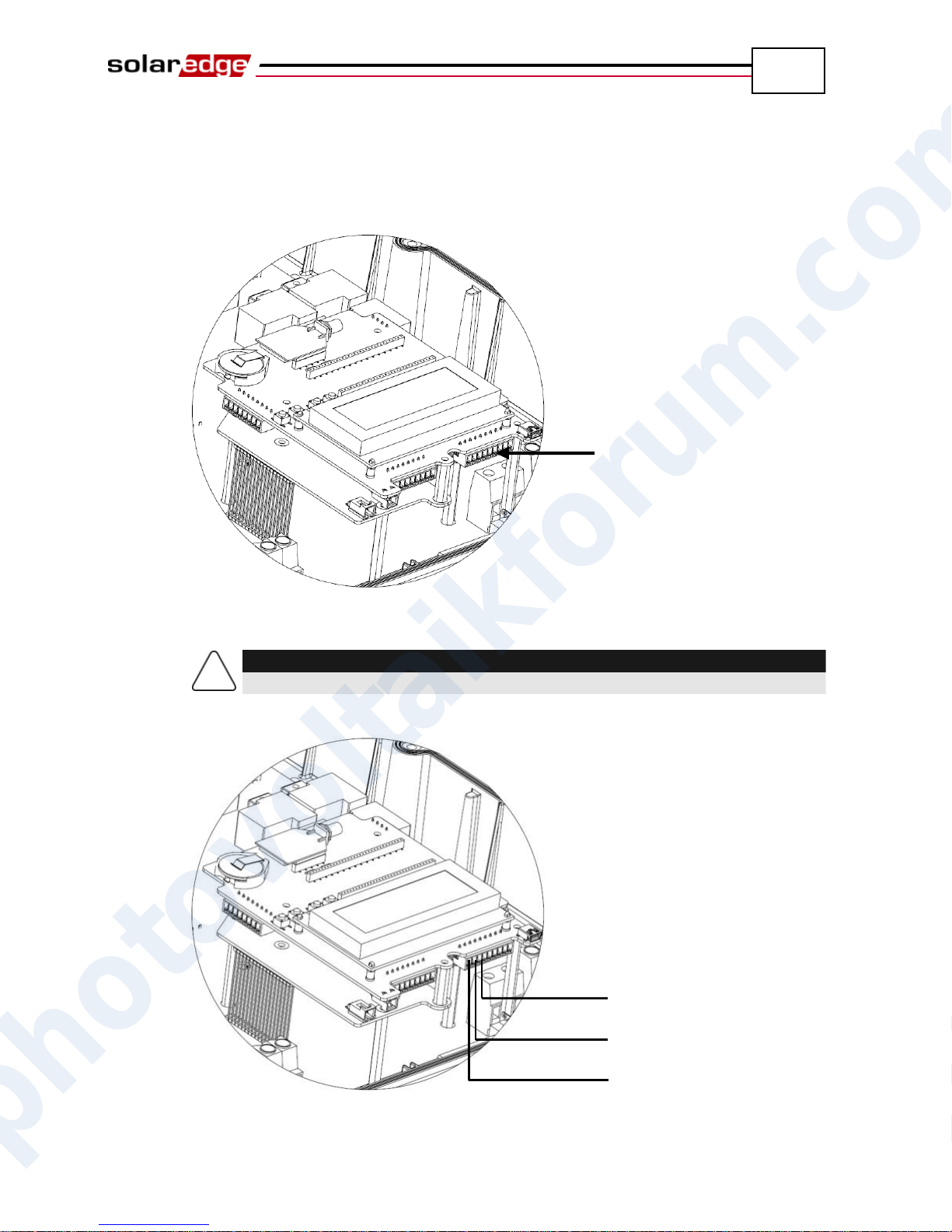
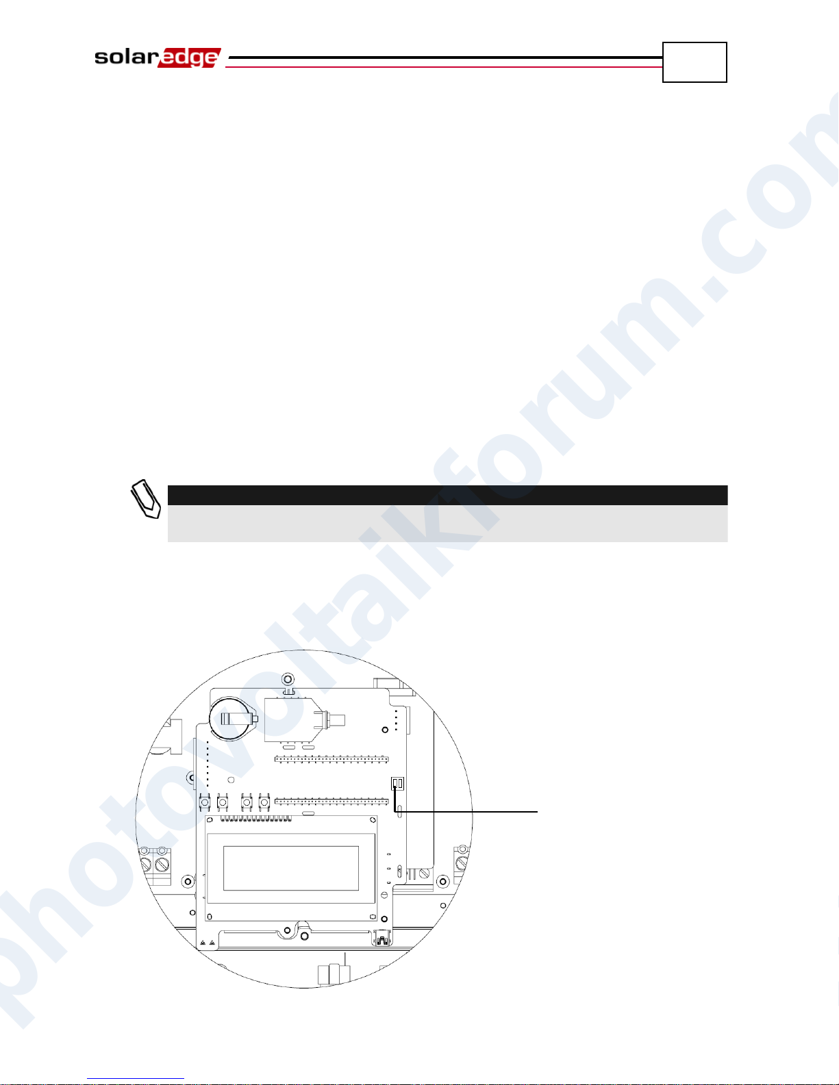
5 The two inverters at the ends of the chain (meaning the first inverter and the
last inverter) must be terminated by switching a termination dip-switch inside
the inverter to ON. The switch is marked SW6 and it is the switch closest to
the ESC button, as shown below:
photovoltaikforum.com
Figure 31: RS485 Termination Switch
Page 58
Setting Up Communication
58
NOTE:
Only the two inverters at the ends of the chain should be terminated for best
performance. The other inverters in the chain should have the termination switch
OFF.
SolarEdge Installation Guide – MAN-01-00057-2.0
6 Choose a single inverter to be the connection point between the RS485 bus
and the SolarEdge Monitoring Server.
7 Connect the Master, as described above, to the SolarEdge Monitoring Server
via either Ethernet, as described in the Creating an Ethernet (LAN)
Connection section on page 49, or RS232, as described in the Creating an
RS232 (UART) Connection section on page 47.
Ensure that you select either the Ethernet or RS232 option under the
Communication Server menu, as described in the Configuring the
Inverter Using the LCD Panel and User Buttons section on page 67.
On the Master inverter under the Communication menu, configure the
RS485 option of the inverter to MASTER, as described in the
Configuring the Inverter Using the LCD Panel and User Buttons section
on page 67.
Select the Slave Detect option to initiate automatic detection of the
Slave inverters that are connected to this Master inverter. This verifies
that they are configured as Slaves.
The Master should report the correct number of slaves. If it does not,
verify the connections and terminations as described above.
8 Verify the connection of the Master to the SolarEdge Server, as described in
the Verifying the Connection section below.
A power reduction interface terminal block is located on the communication
board, shown in Figure 20. You may refer to the SolarEdge Power Reduction
Interface User Guide for more details.
photovoltaikforum.com
Page 59
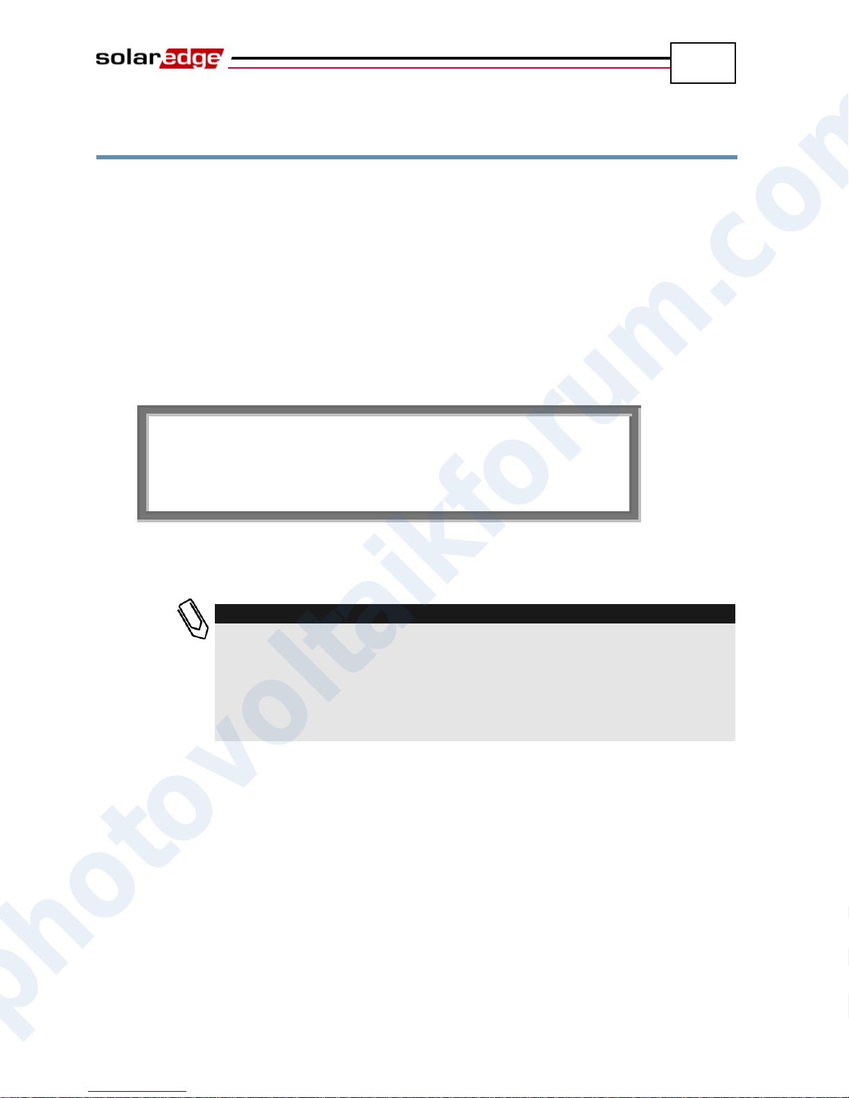
Setting Up Communication
59
V a c [ v ] V d c [ v ] P a c [ w ] 2 3 0 . 7 3 7 1 . 9 2 3 4 9 .
3
P _ O K : X X X / Y Y Y < S _ O K
>
O N
NOTE:
If the S_OK indication is not displayed, then perform the following:
Use another method (unrelated to the SolarEdge inverter) to check
whether the network and modem are operating properly. For example,
connect a laptop to the Ethernet modem and connect to the Internet.
Check whether a firewall or another device is blocking transmission.
Check the configuration of the inverter.
SolarEdge Installation Guide – MAN-01-00057-2.0
Verifying the Connection
► To verify the connection:
1 Verify that the DC circuit breaker is OFF.
2 Verify that the inverter’s ON/OFF switch is still OFF.
3 Turn ON the AC to the inverter by using the circuit breakers on the main
circuit board.
4 Wait for the inverter to connect to the SolarEdge Monitoring Server. This
may take up to two minutes.
5 Verify that the LCD panel displays a window similar to the following:
S_OK: Verify that S_OK appears on the panel to indicate a functioning
connection to the SolarEdge Monitoring Server, which was validated
during the last two minutes.
Troubleshooting Communication
► To troubleshoot a communication problem:
1 Check that the modem or hub/router is functioning properly.
2 Check that the connection to the internal connector on the inverter board is
performed properly through its gland at its bottom.
3 Check that the selected communication option (RS232, Ethernet [LAN],
photovoltaikforum.com
RS485 or ZigBee) is configuring properly using the inverter’s LCD panel.
4 Check whether a firewall or another type of network filter is blocking
communication.
Page 60
Setting Up Communication
60
C o m m : R S 2 3 2 < S _ O K
>
S t a t u s : < O K > x x x x x x x x
R S 4 8 5 < 0 0 0 > < Z B < - - -
>
SolarEdge Installation Guide – MAN-01-00057-2.0
► To troubleshoot Ethernet communication:
When the inverter has Ethernet communication, then the Communication Status
window, as described on page 65, can be used to identify the location of the error.
Instructions for reaching this screen are provided in the Inverter LCD Panel and
User Buttons section, which is described on page 62.
This window displays the inverter’s communication settings. When Ethernet
communication is used, an additional row appears in this screen. It is shown as a
row of eight xs in the picture above. This row is comprised of a string of 1s and
may also have one or more 0s. The location of the first 0 (from the left) indicates
the error location, according to the following order from left to right:
1st: The Ethernet cable is not connected properly. Check the cable pin-out
assignment and cable connection.
2nd: The DHCP IP is not configured properly. Check the router and inverter
configuration.
3rd: Ping to the first hop switch/router failed (LAN error).
4th: Ping to google.com failed (the internet connection is not operating).
5th: Ping to the redundant SolarEdge server #1 failed. Check the address of
the SolarEdge server, as described on page 53.
6th: Ping to the redundant SolarEdge server #2 failed. Check the address of
the SolarEdge server, as described on page 53.
7th: Ping to the redundant SolarEdge server #3 failed. Check the address of
the SolarEdge server, as described on page 53.
8th: Communication with the SolarEdge server failed. Check the address of
the SolarEdge server, as described on page 53.
photovoltaikforum.com
Page 61
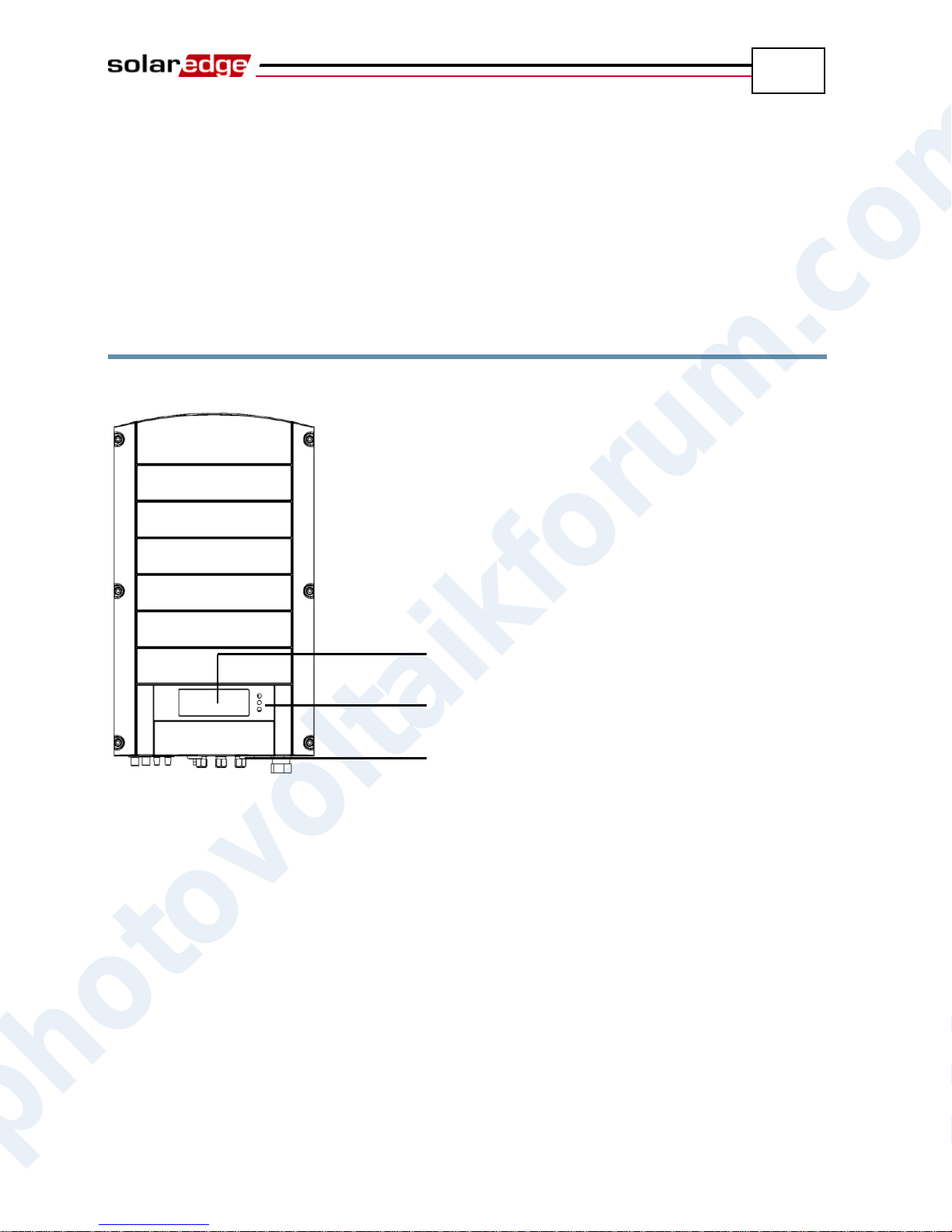
Inverter User Interface
61
LCD
LEDs
LCD Light Button
SolarEdge Installation Guide – MAN-01-00057-2.0
Chapter 7
Inverter User Interface
Inverter LCD Panel and LEDs
The front of the inverter has a small LCD panel and three LEDs, as shown below:
Figure 32: Inverter – Front
The LCD panel has three LED indicators, as follows:
Power Production (Green): Indicates whether the inverter is producing
power or not, as follows:
On: The inverter is producing power.
Blinking: The inverter is in Standby mode, meaning it is preparing to
produce power. The inverter is in Standby mode until enough power is
generated. The inverter then automatically goes to Production mode and
produces power.
Off: The inverter is not producing power. This may be during Night
mode, when the ON/OFF switch is OFF or when an error occurs.
Module Communication (Yellow): This LED blinks quickly each time
photovoltaikforum.com
monitoring information is received from a power optimizer. In addition this
LED blinks while the inverter is being shut down.
Page 62
Inverter User Interface
62
SolarEdge Installation Guide – MAN-01-00057-2.0
Fault (Red): Indicates that an error has occurred. You may refer to the
Appendix A, Errors and Troubleshooting on page 77 for more information. In
addition, this LED blinks while the inverter is being shut down.
All LEDs are on while the inverter is being configured using the buttons inside
the inverter.
Inverter LCD Panel and User Buttons
The following describes the various stages and times of day that you may use the
LCD panel and user buttons:
Normal operation: The LCD panel allows the user to check that the inverter
is working properly. You may refer to the Normal Operation section on
page 62 for a description of this window. Use the LCD button to toggle
through the informative displays.
Inverter startup: After the inverter is turned on and begins producing
power, the LCD panel displays the inverter’s status in the Main Inverter
Status window that shows the total voltage and power, as described in the
Main Inverter Status Window section on page 64.
Inverter shutting down: The inverter automatically goes into Night mode
and turns off the LCD when it is no longer supplied power by at least one
string of minimum length.
After installation of the inverter: The field technician must perform basic
configuration of the inverter, as described in the Configuring the Inverter
Using the LCD Panel and User Buttons section on page 67.
Error messages: In the event of a problem, an error message may be
displayed on the LCD panel. You may refer to Appendix A, Errors and
Troubleshooting on page 77 and the Configuring the Inverter Using the LCD
Panel and User Buttons section on page 67 for more information.
Normal Operation
Pressing the inverter’s LCD light button located on its bottom turns on the LCD's
backlight and displays the messages on the LCD panel.
The backlight is displayed for 30 seconds. This length of time is configurable, as
described on page 72.
photovoltaikforum.com
Page 63
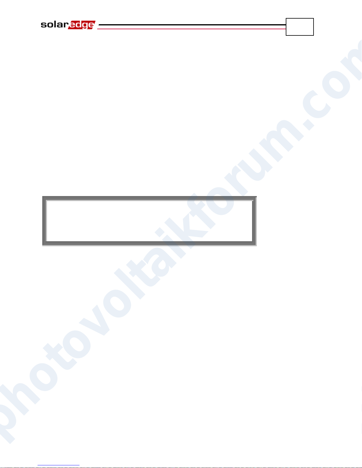
Inverter User Interface
63
V a c [ v ] V d c [ v ] P a c [ w ] 2 3 0 . 7 3 7 1 . 9 2 3 4 9 .
3
P _ O K : X X X / Y Y Y < S _ O K
>
O N
SolarEdge Installation Guide – MAN-01-00057-2.0
The following screens appear, one after the other, when you press the LCD light
button:
Initial Inverter Status Window, below
Main Inverter Status Window, page 64
Energy Meter Window, page 64
Telemetry Window, page 64
ID Status Window, page 65
Communication Status Window, page 65
IP Status Window, page 66
Fan Health Status Window – Three Phase Inverters, page 66
You can toggle between these windows by clicking the LCD light button.
Initial Inverter Status Window
Vac [v]: Specifies the AC output voltage, in Volts.
Vdc [v]: Specifies the DC input voltage, in Volts.
Pac [w]: Specifies the AC output power, in Watts.
P_OK XXX/YYY: Indicates a functioning DC line-communication
connection to the SolarEdge power optimizers, which indicates that telemetry
information was received within the last 10 minutes. XXX is the number of
paired power optimizers for which telemetries have been received by the
inverter in the last hour. YYY is the number of paired power optimizers
identified during the most recent pairing process. Both XXX and YYY
should be the same. If they are not, it may indicate an access issue or pairing
requirement that require your attention.
S_OK: Indicates a functioning connection to the SolarEdge Monitoring
Server, which was validated during the last two minutes. This connection is
not mandatory for power generation.
ON/OFF: Indicates the position of the inverter ON/OFF Switch.
photovoltaikforum.com
Page 64
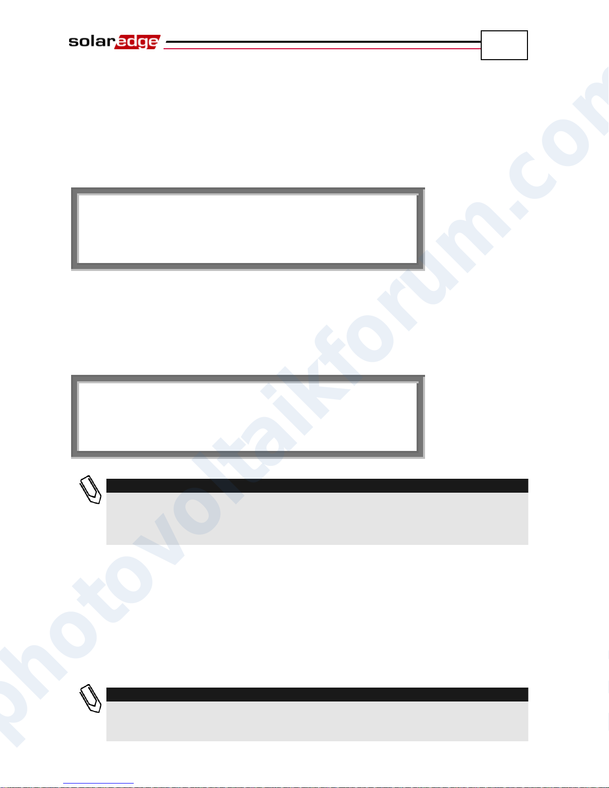
Inverter User Interface
64
V a c [ v ] V D c [ v ] P a c [ w
]
2 3 0 . 7 3 7 1 . 9 3 2 1 0 .
0
F a c [ H z ] P B s _ O k T e m p
5 0 . 0 1 1 2 8 . 2
D a y [ W h ] : 0 . 0 M o n t h [ K W H ] : 0 . 0
Y e a r [ K W h ] : 0 . 0
T o t a l [ K W H ] : 0 . 0
NOTE:
The production data is accumulated according to an internal real-time clock. If the
inverter is connected to the SolarEdge Monitoring Server, it will automatically set the
cloc’'s time. If not, you may use the SolarEdge Configuration Tool to set the clock
setting.
NOTE:
This window is unique in that its backlight is ON by default for 15 minutes after you
press the LCD light button (and not 30 seconds like other windows). This length of
time can be configured, as described on page 72.
SolarEdge Installation Guide – MAN-01-00057-2.0
Main Inverter Status Window
After you press the inverter’s LCD light button to display the window shown
above, you can press it again to display the Inverter Main Status window. This is
the most informative window during the normal course of events, because it
provides a quick overview of power, voltage and inverter heat sink temperature,
as described below:
Energy Meter Window
After you press the inverter’s LCD light button to display the window shown
above, you can press it again to display the Inverter Energy Meter window. This
window displays the total energy [Wh] produced during the last day, month and
year of the inverter, as described below:
Telemetry Window
After you press the inverter’s LCD light button to display the window shown
above, you can press it again to display the Inverter Telemetry window. This
window displays the telemetry of the last power optimizer to report its telemetry
to the inverter, as described below. The display changes as each power optimizer
sends its telemetry information. Each power optimizer sends its telemetry once
within each 5-minute period.
photovoltaikforum.com
Page 65
Inverter User Interface
65
NOTE:
In order to verify proper installation, a technician may want to view the Telemetry
window for some time in order to see that all power optimizers report their telemetries.
M o d u l e # : M 3 2 5 6
E n e r g y [ W h ] : 0 . 0
V d c _ O [ V ] : 6 9 . 5 V d c _ I [ V ] : 2 9 . 5
I D : # # # # # # # # # #
D S P 1 / 2 : 1 . 0 2 1 0 / 1 . 0 0 3 4 C P U : 0 0 0 2 . 0 1 1 1
C o u n t r y : G
B R
C o m m : R S 2 3 2 < S _ O K > S t a t u s : < O K >
R S 4 8 5 < 0 0 0 > < Z B < - - -
>
SolarEdge Installation Guide – MAN-01-00057-2.0
Clicking the LCD light button again redisplays the Initial Inverter Status window,
as described on page 63.
ID Status Window
After you press the inverter’s LCD light button to display the window shown
above, you can press it again to display the Inverter ID window. This window
describes the software version and which country for which the inverter is
configured.
Communication Status Window
After you press the inverter’s LCD light button to display the window shown
above, you can press it again to display the Inverter Communication Status
window. This window displays the communication settings.
photovoltaikforum.com
Page 66
Inverter User Interface
66
I P 1 9 2 . 1 6 8 . 2 . 1 1 9
M S K 2 5 5 . 2 5 5 . 2 5 5 . 0 G W 1 9 2 . 1 6 8 . 2 . 1 M A C 0 - 2 7 - 0 2 - 0 0 - 3 9 - 3
6
F a n H e a l t h I n d i c a t o r F A N # 1 : R e p l a c e
F A N # 2 : O p e r a t i n g
SolarEdge Installation Guide – MAN-01-00057-2.0
IP Status Window
After you press the inverter’s LCD light button to display the window shown
above, you can press it again to display the Inverter IP Status window. This
window describes the Ethernet configuration.
Fan Health Status Window – Three Phase Inverters
After you press the inverter’s LCD light button to display the window shown
above, you can press it again to display the Fan Health Status window. This
window provides information about the health of the inverter’s two fans, as
described below:
Each fan can have one of the following statuses:
Operating
Replace
Not Working
When a fan has the status Replace, the display blinks constantly until it is
replaced, as long as the unit is not in night mode.
The Fault LED does not light when in Replace status.
The Error section displays an error if the fan is faulty. You may refer to
Appendix A, Errors and Troubleshooting on page 77 for a description of the error.
Clicking the LCD light button again redisplays the Initial Inverter Status window,
as described on page 63.
photovoltaikforum.com
Page 67
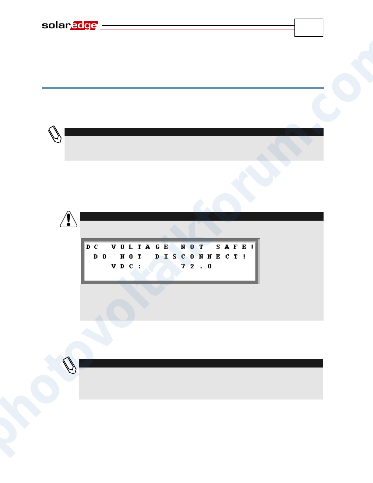
Inverter User Interface
67
NOTE:
This process can also be performed using the SolarEdge configuration tool by
connecting a PC or laptop to the inverter via its RS232/USB management port. This
tool is described in the SolarEdge Configuration Tool User Guide.
WARNING!
If configuration actions are perfomred after the system has been working,, the
following message is displayed:
This message is displayed until the DC is safe.
The default safety voltage is 50 V.
Do not open the cover or open DC conectocrs until the voltage is indicated as
safe or until at least five minutes have passed.
NOTE:
There are two options for configuring the inverter. One is performed by pressing
the external LCD button, which provides access to the most commonly used
options. If you only want to perform pairing, you can do so without opening the
inverter cover, as described in the LCD Button Menu Options section on page 74.
SolarEdge Installation Guide – MAN-01-00057-2.0
Configuring the Inverter Using the
LCD Panel and User Buttons
After installation of the inverter, a field technician can verify and perform basic
configurations of the inverter. This section describes the various LCD messages
and possible configurations using the user buttons.
► To configure the inverter:
1 Verify that the inverter’s ON/OFF switch is OFF.
2 Press the LCD Light button once to turn ON the backlight.
3 The following configuration procedures are performed with the inverter
cover open. Open the cover, as described in the Opening the Cover section on
page 27.
photovoltaikforum.com
Page 68
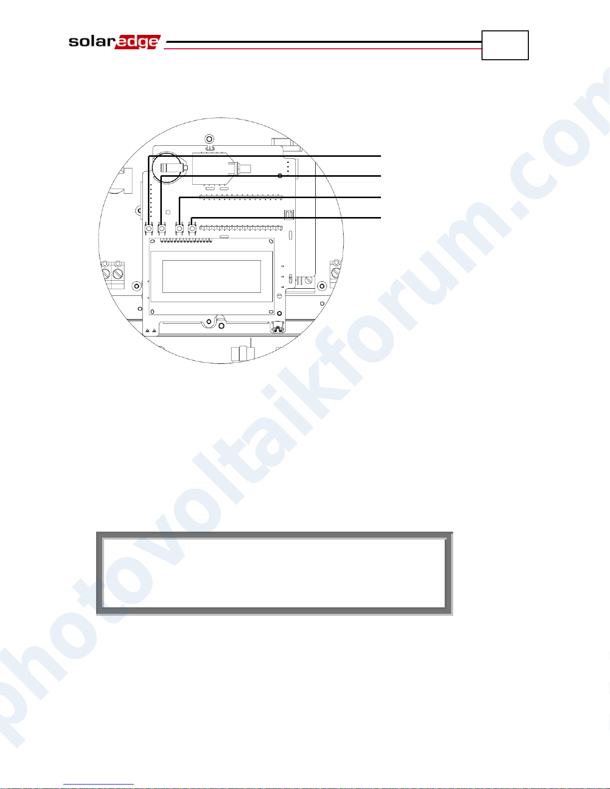
Inverter User Interface
68
P l e a s e e n t e r
P a s s w o r d
* * * * * * * *
Esc
Up (1)
Down (2)
Enter (3)
SolarEdge Installation Guide – MAN-01-00057-2.0
Four buttons for controlling the LCD panel menus are then accessible, as
shown below:
Figure 33: LCD Panel Menu Buttons
Esc: Goes to the beginning of the currently entered parameter or to the
previous menu.
Up (1): Goes up one option in a menu.
Down (2): Goes down one option in a menu.
Enter (3): Confirms the entry or selection of a parameter.
4 Press the Enter button for at least five seconds. The following message is
displayed:
The inverter is now in Setup mode and all its LEDs are lit. The inverter
automatically exits Setup mode if no buttons are pressed for more than two
minutes.
photovoltaikforum.com
Page 69
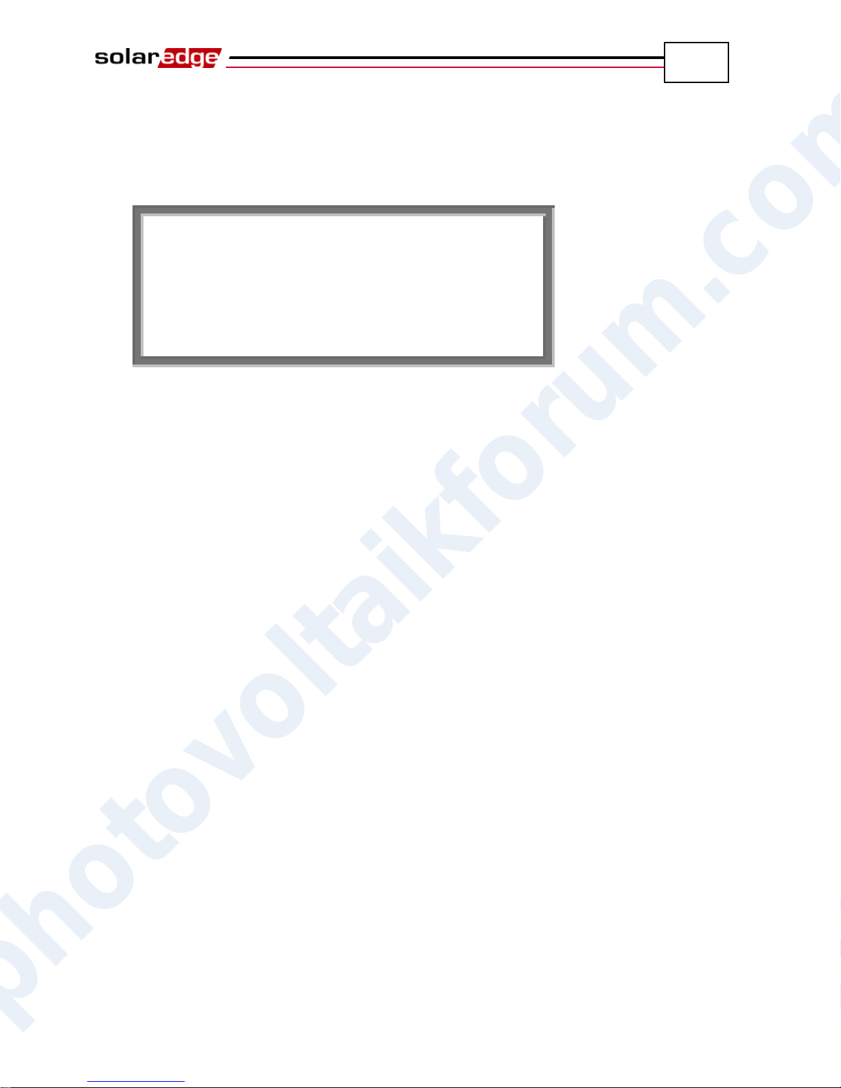
Inverter User Interface
69
* C o u n t r y < G E R >
L a n g u a g e < e n g > T e m p e r a t u r e < C >
D i s p l a y
C o m m u n i c a t i o n
C o u n t e r s
SolarEdge Installation Guide – MAN-01-00057-2.0
5 Use the three right-most buttons inside the inverter (the UP-1, Down-2 and
Enter-3 buttons), shown above, to type in the following default password:
12312312. Inverter passwords are eight digits long, each digit being between
1 and 3. The following message is displayed:
Configure each of these menu options.
photovoltaikforum.com
Page 70
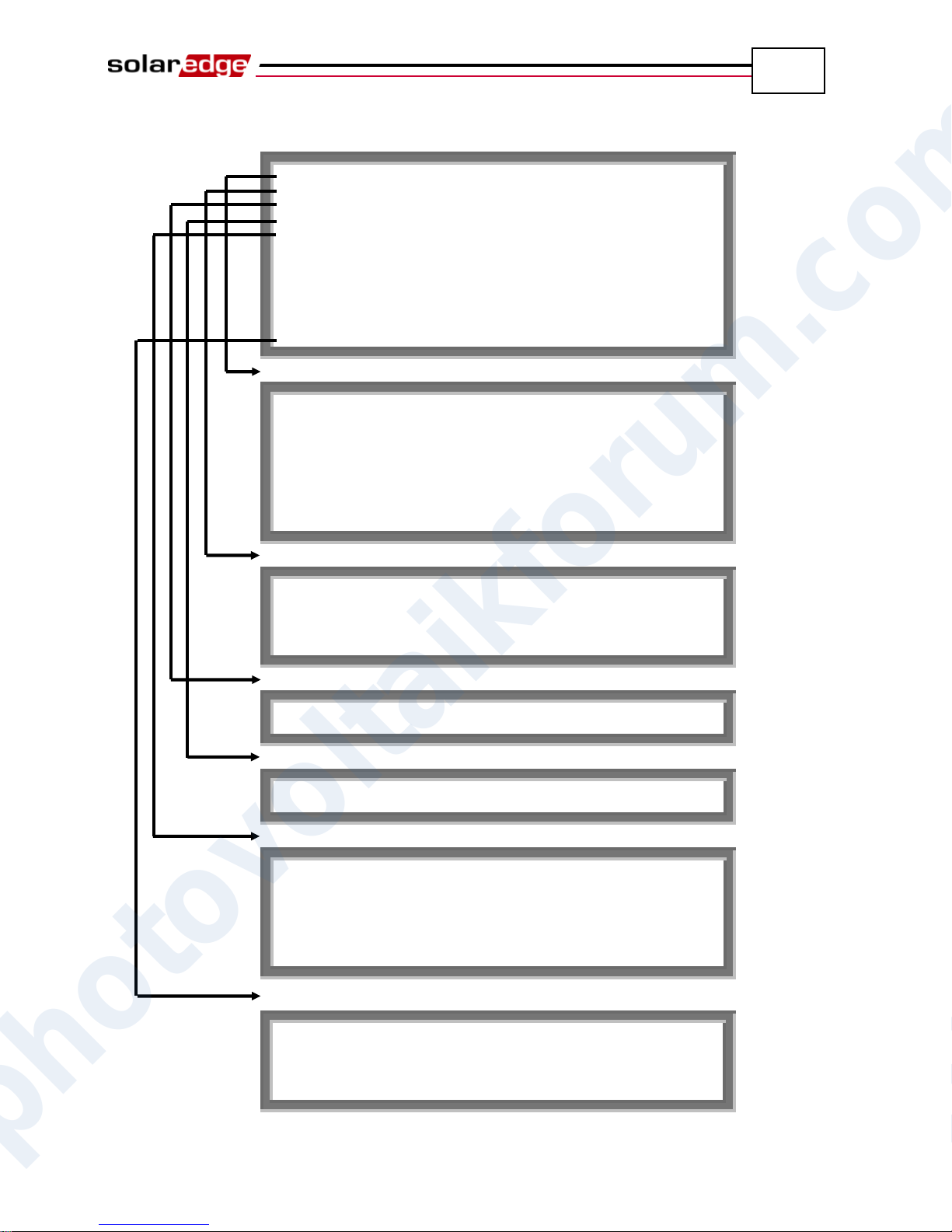
Inverter User Interface
70
C o u n t r y < G E R >
L a n g u a g e < e n g > T e m p e r a t u r e < C >
D i s p l a y
C o m m u n i c a t i o n
C o u n t e r s
I n f o
F a c t o r y R e s e t E r r o r L o g
W a r n i n g L o g
D a t e a n d T i m e P o w e r C o n t r o l
G e r m a n y S p a i n
F r a n c e
I s r a e l U n i t e d K i n g d o m
G r e e c e +
I t a l y B u l g a r i a
C z e c h R e p u b l i c
E n g l i s h
G e r m a n
S p a n i s h F r e n c h
I t a l i a n
C e l s i u s
F a h r e n h e i t
L C D O n T i m e < 3 0 > T L M O n T i m e < 1 5 >
S e r v e r < L A N > B u s < Z i g B e e >
L A N C o n f
R S 4 8 5 C o n f < S > Z I G B E E C o n f < S >
R S 2 3 2 C o n f
M o d b u s C o n f
S h o w S e t t i n g s
S e t D a t e
S e t T i m e S e t T i m e Z o n e
S e t U p d a t e M o d e
SolarEdge Installation Guide – MAN-01-00057-2.0
The following shows a hierarchical tree of the menu options:
Country:
Language:
Temperature:
Display:
Communication:
Date and Time:
photovoltaikforum.com
Page 71

Inverter User Interface
71
S e r v e r < L A N >
B u s < Z i g B e e >
L A N C o n f
R S 4 8 5 C o n f < S >
Z I G B E E C o n f < S >
R S 2 3 2 C o n f
M o d b u s C o n f
L A N
R S 2 3 2
R S 4 8 5
Z i g b e e
N o n e
Z i g b e e P 2 P
Z i g b e e M P
R S 4 8 5 M a s t e r
R S 4 8 5 S l a v e
N o n e
I P C o n f i g
S e t D H C P < E n >
S e t I P
S e t M a s k
S e t G a t e w a y
S e t D N S
S e t S e r v e r A d d r
S e t S e r v e r P o r t
M o d e < P 2 P S l a v e
>
P A N I D
S c a n C h a n n e l
L o a d Z B D e f a u l t
s
G S M
D i r e c t
M o d b u s S e t < E n > S e t P r o t o c o l T y p
e
S e t D e v i c e I D
S e t C h a n n e l F a c t o r y R e s e t
SolarEdge Installation Guide – MAN-01-00057-2.0
Each menu option is described below.
Use the Up and Down buttons inside the inverter to move the asterisk (*) to
the relevant menu option and then press the Enter button to select it. Use the
three rightmost buttons to type in a number if required.
The figure on the following page shows a hierarchical tree of the menu
options for the Communications menu.
Communication:
Server:
Bus:
LAN Conf:
ZIGBEE Conf:
RS232 Conf:
Modbus Conf (see next page)
photovoltaikforum.com
Page 72
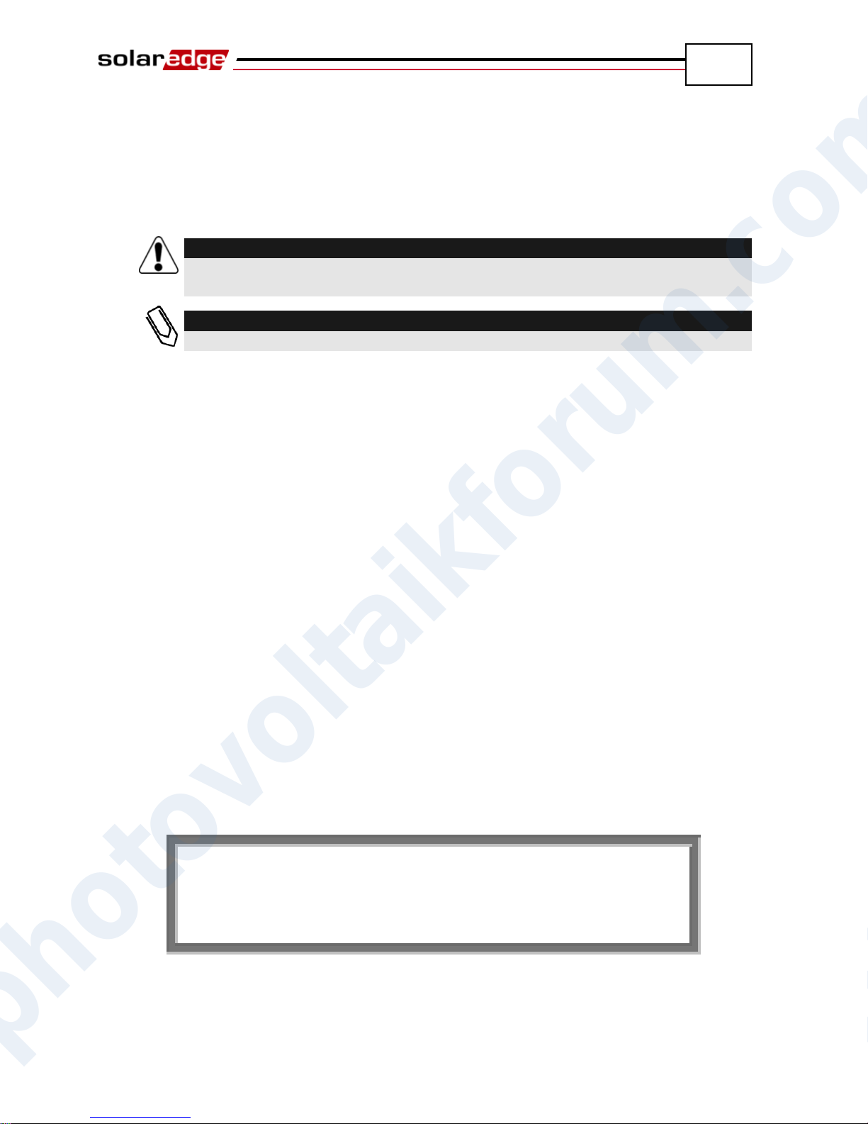
Inverter User Interface
72
WARNING!
The inverter must be configured to the proper country in order to ensure that it
functions properly with that country’s grids.
NOTE:
If an inverter is not configured to any country, then it does not turn ON.
I D : 0 0 0 0 0 0 0 F
D S P 1 V e r : 1 . 8 8
D S P 2 V e r : 0 . 8 1
C P U V e r : 1 . 4 7 2 7
SolarEdge Installation Guide – MAN-01-00057-2.0
Inverter Configuration Menu Options
1 Select the Country option to specify the country in which the inverter is
installed. This parameter may arrive pre-configured. If so, verify that it is set
to the proper country.
If no country is configured, its value is <NONE>. A list of countries is displayed.
A + near the country indicates that another menu will be displayed after selection.
After selecting the country, you are asked to confirm your selection in the
confirmation screen. Toggle to YES and press Enter to confirm.
2 Select the Language option to select the language in which the LCD panel
should display. The inverter may arrive pre-configured to the local language.
3 Select the Temperature option to select the units in which the temperature is
displayed, as shown below:
The display shows either <C> or <F> according to whether Celsius or
Fahrenheit was selected. The default is Celsius.
4 Select the Display option to display the following three options:
LCD On Time <30>: Specifies the number of seconds that the LCD
panel backlight is ON after the LCD light button is pressed. <30>
represents the default value of 30 seconds.
TLM On Time <15>: Specifies the number of minutes that the LCD
panel backlight is ON while viewing the Telemetry window. The default
is 15 minutes.
SW Version: Displays version information describing various firmware
inverter processors, as follows:
ID: Displays the inverter ID, which should be the same as the last
part of the inverter ID that appears on the inverter. You may refer to
the Identifying the Inverter section on page 21 for more details.
photovoltaikforum.com
The next three numbers represent the firmware versions of various
processors.
Page 73
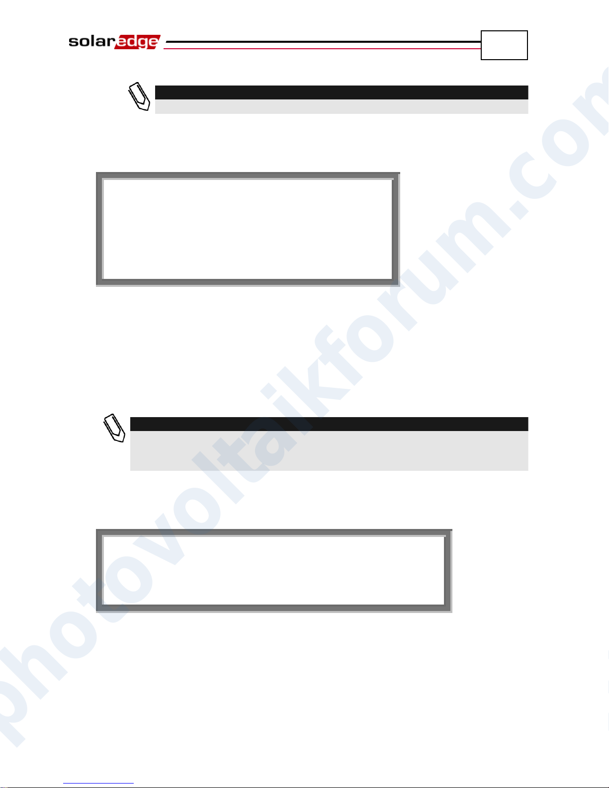
Inverter User Interface
73
NOTE:
Please have these numbers ready when you contact SolarEdge support.
S e r v e r < L A N > B u s < Z i g B e e > L A N C o n f R S 4 8 5 C o n f < S > Z I G B E E C o n f < S > R S 2 3 2 C o n f M o d b u s C o n f
NOTE:
This menu shows only the actual communication options installed in the inverter,
based on the ordering options selected. If a communication option is not installed
in the inverter, the relevant number does not appear in the menu.
T h i s a c t i o n w i l l
R e s e t a l l c o u n t e r s
P l e a s e S e l e c t : N O
SolarEdge Installation Guide – MAN-01-00057-2.0
5 Select the Communication option to define and configure the
communication option used by the inverter to communicate with the
SolarEdge Monitoring Server.
Select option Server to select which communication method is used to
communicate between this inverter and the SolarEdge Monitoring Portal.
Select options LAN, RS232, RS485 or Zigbee to configure the
communication method to the SolarEdge Monitoring Portal. Refer to
Chapter 6, Setting Up Communication on page 45 for a full description
of these communication options:
You can also select the None option if no server communication is required.
6 Select the Counters option to reset all telemetry counters that are displayed
in the Energy Meter window, which is described in the Energy Meter
Window section on page 64.
7 Single phase inverters: Select the Phase Balance option to enable/disable the
inverter’s power balancing option, which enables the connection of three
single-phase inverters to a three-phase grid.
8 Select the Info option to display the Printed Circuit Board ID and the
inverter’s firmware version numbers.
9 Select the Factory Reset option to perform a general reset of the inverter to
photovoltaikforum.com
its default settings.
Page 74
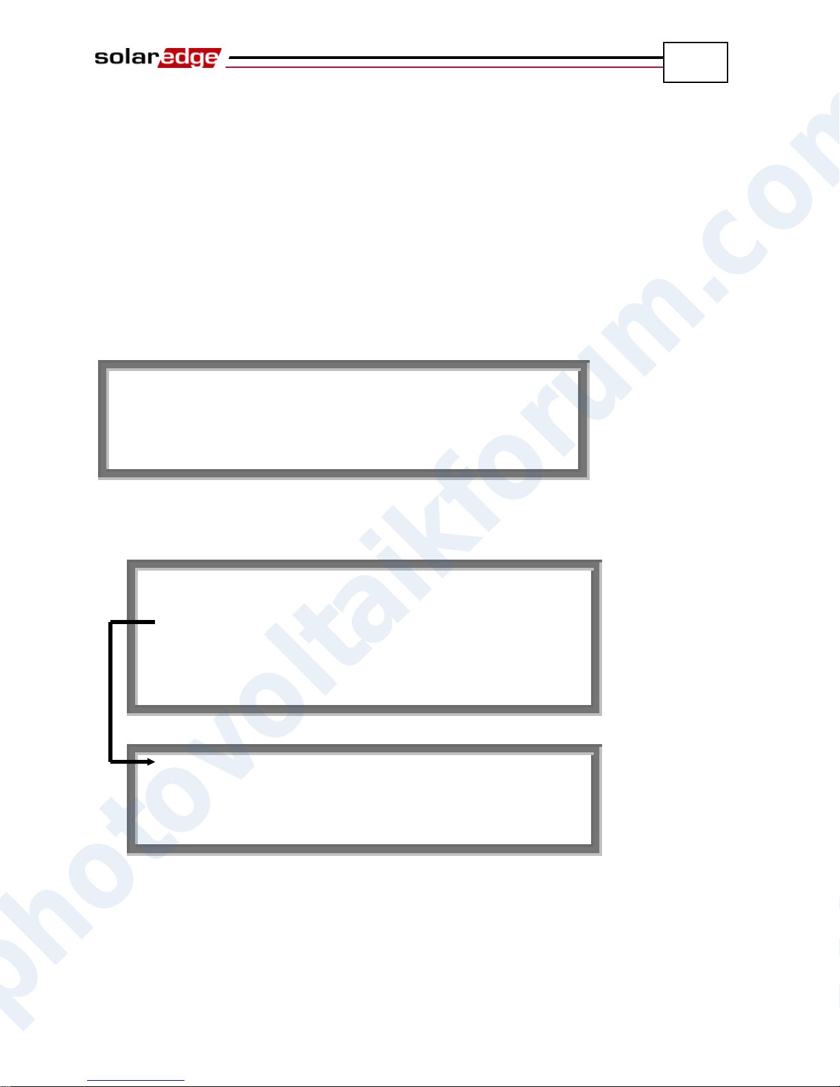
Inverter User Interface
74
K e e p h o l d i n g b u t t o n f o r p a i r i n g , r e l e a s e t o e n t e r m e n u . . . R e m a i n i n g : 3 s e c
O p t i m i z e r P a i r i n
g
B u s S l a v e D e t e c t
C o m m u n i c a t i o n
E r r o r L o g
W a r n i n g L o g
E x i t
S e r v e r < Z i g b e e > B u s < Z i g b e e >
L o a d Z B D e f a u l t s
E x i t
SolarEdge Installation Guide – MAN-01-00057-2.0
10 Select the Error Log option to display the last five errors.
11 Select the Warning Log option to display the last five warnings.
12 Select the Date and Time option to set the date and time of the inverter.
LCD Button Menu Options
The LCD button can also be used for communication setup and to display the
Error log and Warning Log without having to open the inverter
To access the external LCD button menu options, press and hold down the LCD
button until the following message is displayed:
Continue to hold down the button to continue the normal pairing function, which
is displayed and described on page 35. Releasing the button displays the
following menu:
Communication Submenu:
The options presented in these menus are the same as those described in the
Inverter Configuration Menu Options section on page 72, although they are
organized slightly differently.
When using these menus, a short press scrolls down to the next menu option and a
long press selects the item. You can use the Exit options in these menus to move
up one menu level.
photovoltaikforum.com
Page 75
Inverter User Interface
75
SolarEdge Installation Guide – MAN-01-00057-2.0
Configuring the Inverter Using the
SolarEdge Configuration Tool
Two options are provided for configuring the system:
Using the LCD panel, as described in this guide.
Using the SolarEdge configuration tool, which provides a standard Windows
GUI. This tool can be accessed by connecting a computer or laptop to the
inverter through the RS232/USB connector.
This tool provides several additional options than are not accessible using the
LCD manual, such as enabling a firmware upgrade of the inverter and
retrieving a list of the serial numbers of the power optimizers connected to
the inverter for quickly verifying that all power optimizers have been
installed properly. You may refer to the SolarEdge Configuration Tool
Software Guide.
photovoltaikforum.com
Page 76
SolarEdge Installation Guide – MAN-01-00057-2.0
76
Blank page left intentionally
Inverter User Interface
photovoltaikforum.com
Page 77
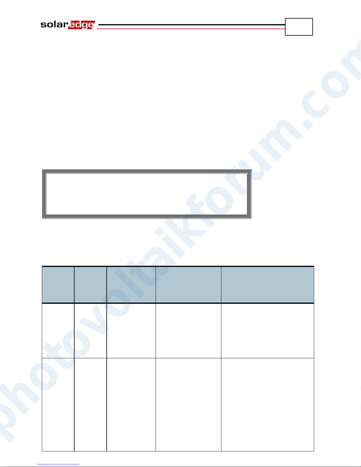
Errors and Troubleshooting
77
E r r o r c o d e X X X
X X X X X X X X X X X X X X X X X X X
X
X X X X X X X X X X X X X X X X X X X
X
Error #
Single
Phase
Inverters
Error #
Three
Phase
Inverters
LCD Message
Description
Troubleshooting
4, 5, 6, 8,
11, 12,
18-23, 39,
42, 45,
48, 132133, 140
45, 48,
50-53,
94,
108-113
SW Error
Internal software
error.
If this fault persists, contact
SolarEdge support.
9, 13
AC Current
Surge
The internal hardware
that measures AC
current has measured
substantially high
output currents. This
may occur because of
changes in the AC
voltage or a switching
load near the site.
If this fault persists:
Check the AC connection
to the inverter.
Ask the grid operator
whether a large surge
source or irregular load
exists near the site.
If the grid does not have
problems contact
SolarEdge support.
SolarEdge Installation Guide – MAN-01-00057-2.0
Appendix A
Errors and Troubleshooting
The inverter LCD panel displays a message when an error occurs.
This appendix lists the error messages that may appear on the inverter’s LCD
panel, describes their meaning and describes how to troubleshoot each one.
Each message may comprise up to two lines of 20 characters each. The following
shows the format of an error message on the inverter LCD panel:
Each error message is displayed for 30 seconds. If the error no longer exists, the
inverter displays the Waking Up message.
The following table lists the error messages that appear on the inverter and
describes how to troubleshoot each one.
photovoltaikforum.com
Page 78
78
Error #
Single
Phase
Inverters
Error #
Three
Phase
Inverters
LCD Message
Description
Troubleshooting
10, 37-38
76-77, 90
Ground
Current - RCD
Ground current
surge. The internal
hardware that
measures ground
fault has measured
substantially high
ground currents.
Ground faults may occur due
to insufficient insulation to
the ground.
DO NOT TOUCH UNINSULATED WIRES!
EXTREME CARE MUST
BE TAKEN WHEN
TROUBLESHOOTING
THIS ERROR.
ELECTROCUTION RISK
EXISTS!
Only a qualified technician
should handle this problem,
and only after taking proper
precautions.
Shut OFF the inverter by
turning the ON/OFF switch
at the bottom of the inverter
OFF and disconnecting the
AC switch.
Wait five minutes for the
input capacitors to
discharge.
Disconnect the DC inputs.
For each DC string,
measure the DC voltage
between DC- and GND and
DC+ and GND with a
1Kohm resistor in parallel
to the volt meter. If a
voltage higher than 2 V is
measured, then the fault is
in this string.
Do not connect strings with
a grounding fault to the
inverter.
A certified PV installer
must fix the faulty string
before connecting it to the
inverter.
Errors and Troubleshooting
SolarEdge Installation Guide – MAN-01-00057-2.0
photovoltaikforum.com
Page 79
Errors and Troubleshooting
79
Error #
Single
Phase
Inverters
Error #
Three
Phase
Inverters
LCD Message
Description
Troubleshooting
14
58/59/60
AC Voltage
Too High
(Line 1/2/3)
AC voltage surge.
The internal
hardware that
measures AC
voltage has
measured
substantially high
instantaneous
output voltage.
If this fault persists:
Check the AC connection
to inverter.
Ask the grid operator
whether a large surge
source or irregular load
exists near the site.
Verify that the gauge of the
AC output wire size is large
enough, and if not, use a
larger gauge wire.
15
102
DC Voltage
Too High
DC overvoltage. The
input DC voltage
exceeds the
maximum level that
is supported.
The SolarEdge system should
normally eliminate DC
overvoltage errors. When DC
overvoltage is detected, the
inverter shuts off the power
optimizers and restarts the
inverter.
If this fault persists:
Turn the inverter OFF.
After at least five minutes,
the LCD panel should show
a safety voltage of 1 V
*string length. If it does
not, check which string is
malfunctioning and check
its connections to the
inverter.
Verify that no PV modules
are connected directly to
the inverter without a
power optimizer.
Recommission all inverters
in the site, as described in
Chapter 4, Commissioning
the Installation on page 33.
16, 27
123
Measurement
Error
Internal hardware
error.
If this fault persists, contact
SolarEdge support.
SolarEdge Installation Guide – MAN-01-00057-2.0
photovoltaikforum.com
Page 80
Errors and Troubleshooting
80
Error #
Single
Phase
Inverters
Error #
Three
Phase
Inverters
LCD Message
Description
Troubleshooting
17
104
Temperature
Too High
Over temperature.
If this fault persists, then:
Verify that there are proper
clearance distances around
the inverter, as described in
the Chassis Clearance
section on page 21.
Make sure that the heat-
sink fins are clear of dirt
and obstacles.
Check whether the inverter
is installed in an area that is
too hot.
Reinstall in a cooler
location.
24 Faulty Temp.
Sensor
Broken or
unconnected
Temperature sensor.
If this fault persists, contact
SolarEdge support.
25
121
Isolation Fault
The inverter
detected that the PV
solar generator is not
properly isolated
from ground earth.
Isolation is checked
every time the
inverter starts
operation.
If this fault persists:
Check the PV installation
for isolation problems and
ground leakage.
Only a certified PV
installer must fix a faulty
string before connecting it
to the inverter.
26
122
Faulty AC
Relay
The AC relay failed
during wake-up
tests.
If this fault persists:
Disconnect inverter from
AC grid.
Contact SolarEdge support.
28 RCD Sensor
Error
The RCD
measurement
mechanism has
failed during the
wake-up test phase.
If this fault persists, contact
SolarEdge support.
SolarEdge Installation Guide – MAN-01-00057-2.0
photovoltaikforum.com
Page 81
Errors and Troubleshooting
81
Error #
Single
Phase
Inverters
Error #
Three
Phase
Inverters
LCD Message
Description
Troubleshooting
29-30
Phase Balance
Error
The monitoring
hardware that
checks the balance
of each phase (L1-N
and L2-N) has
exceeded its limit.
This error is checked
only in the USA.
Check the grid connection.
Check the GND wire
connection.
Check the L1, L2 and
Neutral wire connections.
Verify symmetric load
between L1 and L2.
Consult the local grid
authority.
31, 33
64/65/66
AC Voltage
Too High
(Line 1/2/3)
Grid voltage is
above the limit
permitted in this
country.
Turn off the inverter and
verify AC grid voltage.
If the inverter is located far
from the connection point
to the grid, then use a wider
gauge AC wire.
Consult the grid operator.
If permitted by local
authorities, use the
SolarEdge Configuration
Tool to change the settings.
Refer to the SolarEdge
Installation Tool User
Guide for mode detail.
32, 41
61/62/63,
67/68/69
AC Voltage
Too Low (Line
1/2/3)
Grid Voltage is
below the limit
permitted in this
country.
Consult the grid operator.
If permitted by local
authorities, use the
SolarEdge Configuration
Tool to change the settings.
Refer to the SolarEdge
Installation Tool User
Guide for mode detail.
34, 35
79/80/81,
82/83/84
AC Freq Too
High / Low
(Line 1/2/3)
Grid frequency is
above / below the
limit permitted in
this country.
Consult the grid operator.
If permitted by local
authorities, use the
SolarEdge Configuration
Tool to change the settings.
Refer to the SolarEdge
Installation Tool User
Guide for mode detail.
SolarEdge Installation Guide – MAN-01-00057-2.0
photovoltaikforum.com
Page 82
Errors and Troubleshooting
82
Error #
Single
Phase
Inverters
Error #
Three
Phase
Inverters
LCD Message
Description
Troubleshooting
36
72/74/75
DC Injection
(Line 1/2/3)
DC feed detected on
the AC output.
If this fault persists, contact
SolarEdge support.
40 Islanding
AC grid voltage
malfunctions. The
inverter has shut off
due to islanding.
When AC voltage returns, the
inverter should restart after
some time (time depends on
country grid connection
codes)
If this fault persists, then
consult with the grid operator
whether frequent AC
disruptions have occurred at
the site.
43 Isolation Fault
PV Isolation fault.
The inverter has
detected the PV
solar generator is not
properly isolated
from ground earth.
The isolation is
checked every time
before the inverter
starts operation.
If the problem persists:
Check the PV installation
for isolation problems and
ground leakage.
Only a certified PV
installer must fix the faulty
string before connecting it
to the inverter.
44
44
No Country
Selected
The inverter is not
configured to any
country.
Select the country, as
described on page 72.
46
(single
phase
inverter)
Phase
Unbalance
Change the Phase Balance
option in the inverter’s LCD
menu to Disable.
134
95, 106,
120,
125-126
HW Error
Internal hardware
error.
If this fault persists, contact
SolarEdge support.
SolarEdge Installation Guide – MAN-01-00057-2.0
photovoltaikforum.com
Page 83
Errors and Troubleshooting
83
Error #
Single
Phase
Inverters
Error #
Three
Phase
Inverters
LCD Message
Description
Troubleshooting
144
Islanding –
Passive
AC grid voltage
malfunctions. The
inverter has shut off
due to islanding.
When AC voltage returns the
inverter should restart after
some time (time depends on
country grid connection
codes)
If the problem persists, then
consult with the grid operator
whether frequent AC
disruptions have occurred at
the site.
145
UDC Max
DC overvoltage. The
input DC voltage
exceeds the
maximum level that
is supported.
The SolarEdge system should
normally eliminate DC
overvoltage errors. When DC
overvoltage is detected, the
inverter shuts off the power
optimizers and restarts the
inverter.
If the problem persists, then:
Turn OFF the ON/OFF
switch at the bottom of the
inverter. After at least five
minutes, the LCD panel
should show a low safety
voltage equal to 1 V *string
length. Otherwise, check
which string is
malfunctioning and recheck
its connections to the
inverter.
Verify that no PV modules
are connected directly to
the inverter without a
power optimizer.
Recommission all inverters
in the site, as described in
Chapter 4, Commissioning
the Installation on page 33.
SolarEdge Installation Guide – MAN-01-00057-2.0
photovoltaikforum.com
Page 84
Errors and Troubleshooting
84
Error #
Single
Phase
Inverters
Error #
Three
Phase
Inverters
LCD Message
Description
Troubleshooting
146
103, 119
UDC Min / DC
Voltage Too
Low
The input DC
voltage is below the
minimum level that
is supported.
Turn the inverter off and then
on. If this fault persists,
contact SolarEdge support.
49
Communication
Error
Internal software
error.
If this fault persists, contact
SolarEdge support.
78
Grid Sync
Error
Grid voltage or
frequency is
unstable.
If this fault persists, contact
SolarEdge support.
91/92/93,
96/97/98
AC Over
Current Line
1/2/3
Grid error.
If this fault persists, contact
SolarEdge support.
99-101
AC Voltage
Too High Line
1/2/3
Grid error.
Turn the inverter off and then
on. If this fault persists,
contact SolarEdge support.
105
Temperature
Too Low
Under temperature.
If this fault persists, reinstall
the inverter in a warmer
place.
124
Ground
Current – RCD
Internal hardware
error.
If this fault persists, contact
SolarEdge support.
SolarEdge Installation Guide – MAN-01-00057-2.0
photovoltaikforum.com
Page 85
Technical Specifications
85
SE2200
SE3000
SE3500
SE4000
SE4000-16A
SE5000
SE6000
Output
Rated AC Power
Output
2200
3000
3500
4000
4000
5000i
6000
W
Maximum AC Power
Output
2200
3000
3500
4000
4000
5000i
6000
W
AC Output Voltage
(Nominal)
220 / 230
Vac
AC Output Voltage
Range
184 - 264.5
Vac
AC Frequency
(Nominal)
50 / 60 ± 5
Hz
Maximum
Continuous Output
Current
12
16.5
19.5ii
22
16
27
iii
27
A
Residual Current
Detector / Residual
Current Step
Detector
300 / 30
mA
Utility Monitoring,
Islanding Protection,
Country
Configurable
Thresholds
Yes
SolarEdge Installation Guide – MAN-01-00057-2.0
Appendix B
Technical Specifications
The tables in this appendix provide the technical specifications of the SolarEdge
system components.
Single Phase Inverter
photovoltaikforum.com
Page 86
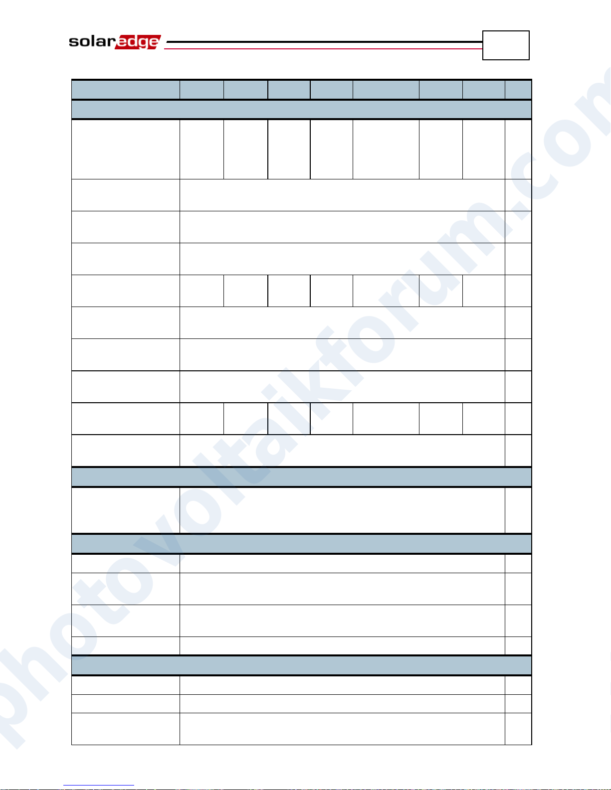
Technical Specifications
86
SE2200
SE3000
SE3500
SE4000
SE4000-16A
SE5000
SE6000
Input
Recommended
Maximum DC
Power*
(Module STC)
2400
3200
3700
4200
4200
5300
6200
W
Transformer-less,
Ungrounded
Yes
Maximum Input
Voltage
500
Vdc
Nominal DC Input
Voltage
350
Vdc
Maximum Input
Current
8.5
11.5
13.5
15.5
15.5
19.5
iv
23
Adc
Reverse-Polarity
Protection
Yes
Ground-Fault
Isolation Detection
600 kΩ Sensitivity
Maximum Inverter
Efficiency
97.8
%
European Weighted
Efficiency
97.6
97.6
97.5
97.5
97.5
97.4
97.4
%
Nighttime Power
Consumption
< 2.5
W
Additional Features
Supported
Communication
Interfaces
RS485, RS232, USB, Ethernet, Zigbee (optional)
Standards Compliance
Safety
IEC-62103 (EN50178), Draft IEC-62109
Grid Connection
Standards
VDE 0126-1-1, AS-4777, RD-1663, DK 5940
Emissions
IEC61000-6-2, IEC61000-6-3, IEC61000-3-11, IEC61000-3-12,
FCC part15 class B
RoHS
Yes
Installation Specifications
AC Output
Cable Gland - Diameter 11-17
mm
DC Input
MC4
Maximum
Installation Height
2000m
SolarEdge Installation Guide – MAN-01-00057-2.0
photovoltaikforum.com
Page 87
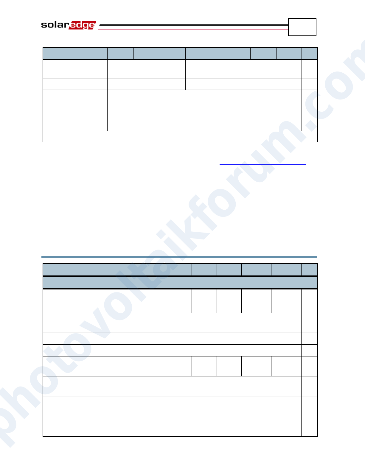
Technical Specifications
87
SE2200
SE3000
SE3500
SE4000
SE4000-16A
SE5000
SE6000
Dimensions
(HxWxD)
540 x 315 x 172
540 x 315 x 191
mm
Weight
19
20.5
kg
Cooling
Natural Convection
Operating
Temperature Range
-20 to +50**
°C
Protection Rating
IP65 – Outdoor and Indoor
Bracket Mounted (Bracket Provided)
SE7k
SE8k
SE9k
SE10k
SE12.5k
SE15k
Output
Rated AC Power Output
7000
8000
9000
10000
12500
15000
VA
Maximum AC Power Output
7000
8000
9000
10000
12500
15000
VA
AC Output Voltage – Line to Line /
Line to Neutral (Nominal)
380/220; 400/230
Vac
AC Output Voltage Range
184 – 264.5
Vac
AC Frequency
50/60 ± 5
Hz
Maximum Continuous Output
Current (per Phase)
11.5
13
14.5
16
20
23
A
Residual Current Detector /
Residual Current Step Detector
300 / 30
mA
Grid Supported – Three Phase
3 / N / PE ; 230 / 400
V
Utility Monitoring, Islanding
Protection, Country Configurable
Thresholds
Yes
SolarEdge Installation Guide – MAN-01-00057-2.0
* Higher input DC power may be installed; analyze yearly AC performance.
** For inverter power de-rating refer to the application note at the following link: http://www.solaredge.com/files/pdfs/se-
temperature-derating-note.pdf
i
4600 in Germany and in the Czech Republic
ii
16 in the UK, Poland, Portugal and Denmark
iii
25 in Germany and the Czech Republic
iv
17.5 in Germany and the Czech Republic
Three Phase Inverter
photovoltaikforum.com
Page 88
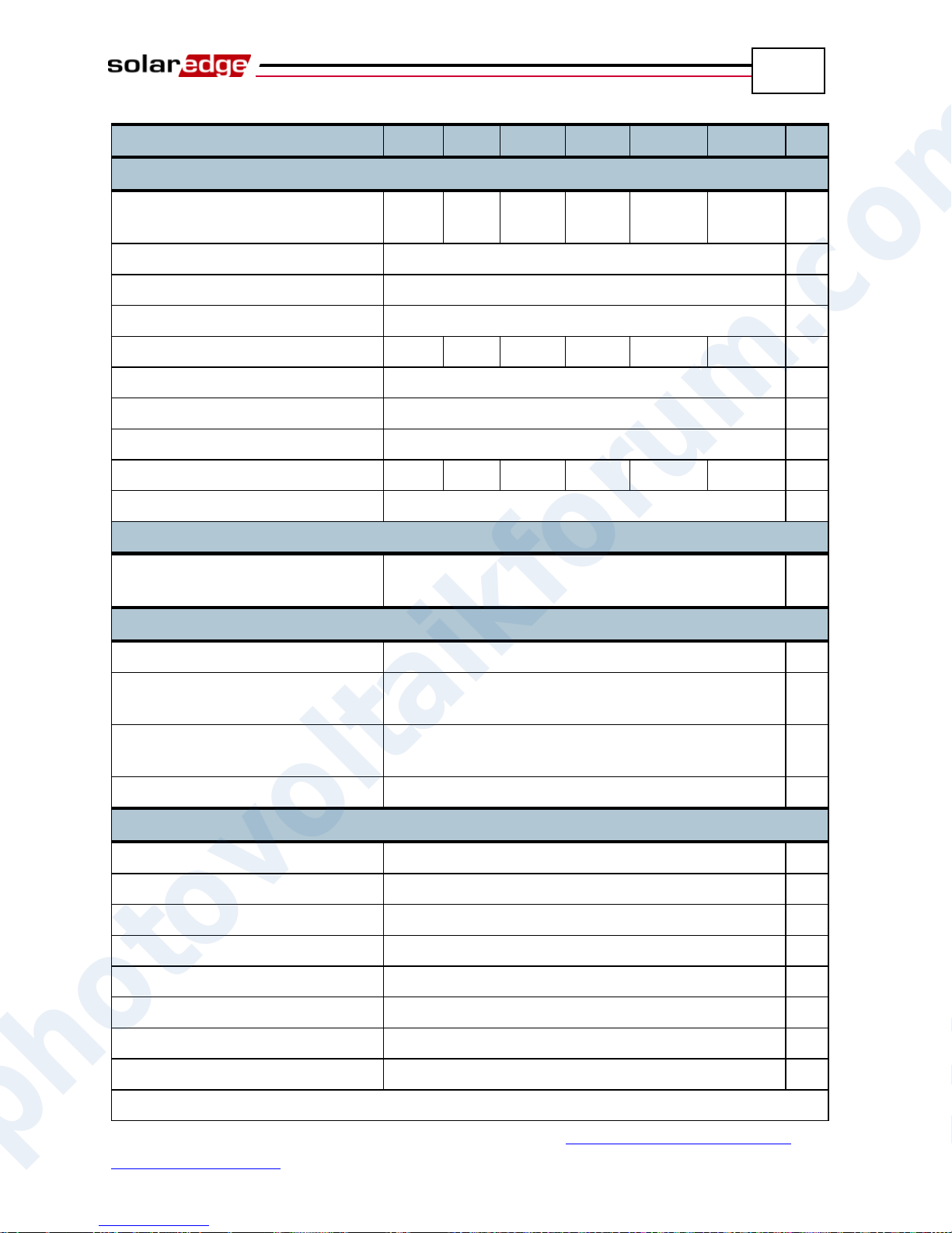
Technical Specifications
88
SE7k
SE8k
SE9k
SE10k
SE12.5k
SE15k
Input
Recommended Maximum DC
Power (Module STC)
7700
8800
9900
11000
13000
13700
W
Transformer-less, Ungrounded
Yes
Maximum Input Voltage
950
Vdc
Nominal DC Input Voltage
750
Vdc
Maximum Input Current
12
13.5
15
16.5
21
22
Adc
Reverse-Polarity Protection
Yes
Ground-Fault Isolation Detection
600 kΩ Sensitivity
Maximum Inverter Efficiency
98
%
European Weighted Efficiency
97.7
97.6
97.6
97.5
97.4
97.4
%
Nighttime Power Consumption
< 2.5
W
Additional Features
Supported Communication
Interfaces
RS485, RS232, Ethernet, Zigbee (optional)
Standards Compliance
Safety
IEC-62103 (EN50178), Draft IEC-62109, UL1741
Grid Connection Standards
VDE-AR-N-4105, VDE 0126-1-1, AS-4777,
RD-1663, DK 5940, IEEE1547, NEC
Emissions
IEC61000-6-2, IEC61000-6-3, IEC61000-3-11,
IEC61000-3-12, FCC part15 class B
WEEE, RoHS
Yes
Installation Specifications
AC Output
Cable Gland - diameter 11-17
mm
DC Input
MC4
Maximum Installation Height
2000
m
Dimensions (W x L x H)
540 x 315 x 260
mm
Weight
32
kg
Operating Temperature Range
-20 – +60*
°C
Cooling
Fan (user replaceable)
Protection Rating
IP65 – Outdoor and Indoor
Bracket Mounted (Bracket Provided)
SolarEdge Installation Guide – MAN-01-00057-2.0
* For inverter power de-rating refer to the application note at the following link: http://www.solaredge.com/files/pdfs/se-
photovoltaikforum.com
temperature-derating-note.pdf
Page 89
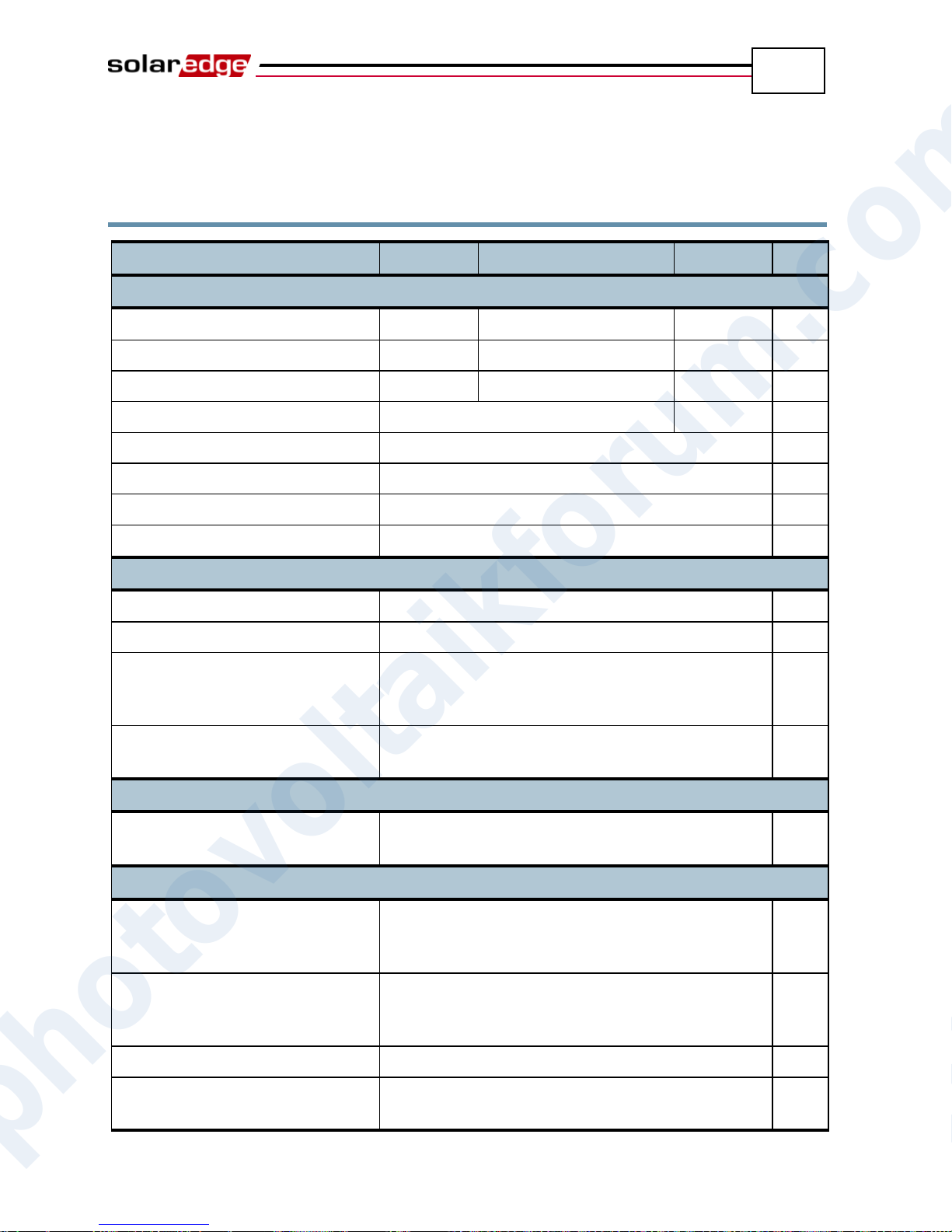
Technical Specifications
89
OP250-LV
OP300-MV/OP400-MV
OP400-EV
Input
Rated Input DC Power
250
300/400
400
W
Absolute Maximum Input Voltage
55
75
125
Vdc
MPPT Operating Range
5 - 55
5 - 75
15-125
Vdc
Maximum Input Current
10
7
Adc
Reverse-Polarity Protection
Yes
Maximum Efficiency
99.5
%
Weighted Efficiency
98.8
%
Overvoltage Category
II
Output During Operation (Power Optimizer Connected to Operating Inverter)
Maximum Output Current
15
Adc
Operating Output Voltage
5 - 60
Vdc
Total Maximum String Voltage
(Controlled by Inverter) - US and
EU 1-ph
500
Vdc
Total Maximum String Voltage
(Controlled by Inverter) - EU 3-ph
950
Vdc
Output During Standby (Power Optimizer Disconnected from Inverter or Inverter Off)
Safety Output Voltage per Power
Optimizer
1
Vdc
PV System Design
Minimum Number of Power
Optimizers per String (1 or More
Modules per Power Optimizer)
8 (1-ph system) / 16 (3-ph system)
Maximum Number of Power
Optimizers per String (1 or More
Modules per Power Optimizer)
25 (1-ph system) / 50 (3-ph system)
Maximum Power per String
5250 (1-ph system) / 11250 (3-ph system)
W
Parallel Strings of Different
Lengths or Orientations
Yes
SolarEdge Installation Guide – MAN-01-00057-2.0
OP250-LV, OP300-MV, OP400-MV and
OP400-EV
photovoltaikforum.com
Page 90
Technical Specifications
90
OP250-LV
OP300-MV/OP400-MV
OP400-EV
Standard Compliance
EMC
FCC Part15 Class B, IEC61000-6-2, IEC61000-6-3
Safety
IEC-62103 (class II safety), UL1741
Material
UL-94 (5-VA), UV Resistant
RoHS
Yes
Installation Specifications
Dimensions (W x L x H)
120 x 130 x3 7 / 4.72 x 5.11 x 1.45
mm/in
Weight
450 / 1.0
g / lb
Maximum Installation Height
2000m
Output PV Wire
0.95 m / 3 ft length ; 6 mm2 ; MC4
Input Connector
MC4 / MC3 / Tyco / H+S
Operating Temperature Range
-40 – +65 / -40 – +150
˚C/˚F
Protection Rating
IP65 / NEMA 4
Relative Humidity
0 - 100
%
SolarEdge Installation Guide – MAN-01-00057-2.0
photovoltaikforum.com
Page 91
Power Optimizer Mechanical Specifications
91
NOTE:
SolarEdge does not provide the screws, nuts or washers because the required sizes
and lengths vary for different racks.
CAUTION:
Before installing directly on the module or module frame, first consult the module
manufacturer for information about the proper positioning and its impact on the
module warranty.
CAUTION:
Do not drill through the power optimizer or through the mounting holes. The strong
vibrations created by the drill can damage the power optimizer.
SolarEdge Installation Guide – MAN-01-00057-2.0
Appendix C
Power Optimizer Mechanical
Specifications
This appendix presents the mechanical specifications for the SolarEdge power
optimizers.
Use M6 (1/4”) screws and washers to secure the power optimizer units to the
racking.
Mark all mounting hole locations.
Each power optimizer must be attached to the rack using both mounting
holes.
Drill the holes.
photovoltaikforum.com
Page 92
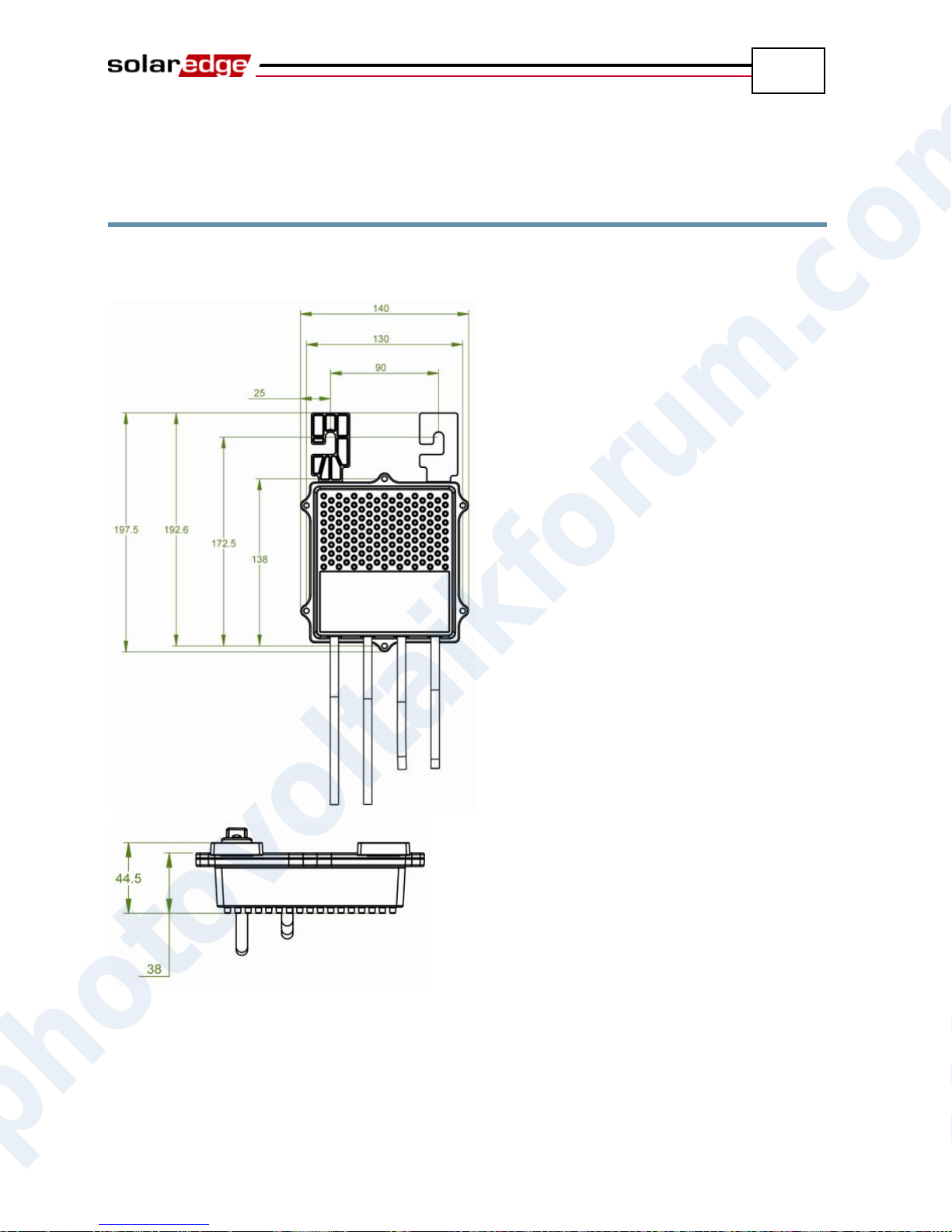
Power Optimizer Mechanical Specifications
92
SolarEdge Installation Guide – MAN-01-00057-2.0
OP250-LV, OP300-MV, OP400-MV,
OP400-EV Power Optimizers
The following figure shows the mechanical specifications for the OP250-LV,
OP300-MV, OP400-MV and OP400-EV power optimizers:
Figure 34: Power Optimizer Mechanical Specifications
photovoltaikforum.com
Page 93
Safe DC
93
WARNING!
The Safe DC voltage is only guaranteed when using modules of up to:
95Voc when using the single phase inverter
70Voc when using the three phase inverter
SolarEdge Installation Guide – MAN-01-00057-2.0
Appendix D
Safe DC
When AC supply to the inverter is shut off, by shutting off the AC breaker at the
site, or when the inverter ON/OFF switch is turned to OFF, the DC voltage drops
to a safe voltage of 1V per optimizer.
The SolarEdge inverters are certified for compliance with IEC 60947-3:1999 +
Corrigendum: 1999 + A1:2001 + Corrigendum 1:2001 + A2:2005; DIN EN
60947-3; VDE 0660-107:2006-03; IEC 60364-7-712:2002-05 and DIN VDE
0100-712:2006-06 as a disconnection device for PV generators, meaning that they
can replace a DC disconnect.
In compliance with this standard, the disconnection mechanism operates as
follows:
Turn the inverter ON/OFF switch, located at the bottom of the inverter, to
OFF, or disconnect the AC by shutting off the AC breaker at the site.
The DC voltage displayed on the inverter LCD begins to decrease. If the AC
breaker was shut off, the LCD does not display. In this case, wait five
minutes.
When the DC voltage reaches a safe voltage then the PV connectors at the
input to the inverter can be disconnected. A galvanic separation then exists
between the PV array and the inverter.
The disconnection is safe even under single fault conditions.
photovoltaikforum.com
Page 94
SolarEdge Installation Guide – MAN-01-00057-2.0
94
Blank page left intentionally
Safe DC
photovoltaikforum.com
Page 95
Limited Product Warranty
95
SolarEdge Installation Guide – MAN-01-00057-2.0
Appendix E
Limited Product Warranty
This SolarEdge Limited Warranty covers defects in workmanship and materials of the
products for the applicable warranty period set out below:
Power optimizers: 25 years commencing on the earlier of: (i) 3 months from the date the
power optimizers are delivered by SolarEdge; and (ii) the installation of the power
optimizers, provided, however, that for the power optimizer, the Warranty Period shall not
exceed the warranty period provided by the applicable module manufacturer.
Inverters: 12 years commencing on the earlier of: (i) 3 months from the date the Inverters
are delivered by SolarEdge; and (ii) the installation of the Inverters.
The Limited Warranty does not apply to ancillary equipment and components sold
separately from the Products, such as, for example, cables, wires and connectors, whether
supplied by SolarEdge or others.
The Limited Warranty only applies to the buyer who has purchased the Products from an
authorized seller of SolarEdge for use in accordance with their intended purpose. The
Limited Warranty may be transferred from buyer to any assignee, and will remain in effect
for the time period remaining under the foregoing warranties, provided that the Products
are not moved outside its original country of installation and any reinstallation is done in
accordance with the installation directions and use guidelines accompany the Products
(collectively the “Documentation”).
If, during the applicable Warranty Period, buyer discovers any defect in workmanship and
materials and seeks to activate the Limited Warranty, then buyer shall, promptly after such
discovery, report the defect to SolarEdge by sending an email to [email protected]
with the following information: (i) a short description of the defect, (ii) the Product’s serial
number, and (iii) a scanned copy of the purchase receipt or warranty certificate of the
applicable Product.
Upon buyer’s notification, SolarEdge shall determine whether the reported defect is
eligible for coverage under the Limited Warranty. The Product’s serial number must be
legible and properly attached to the Product in order to be eligible for Warranty coverage.
If SolarEdge determines that the reported defect is not eligible for coverage under the
Limited Warranty, SolarEdge will notify buyer accordingly and will explain the reason
why such coverage is not available. If SolarEdge determines that the reported defect is
eligible for coverage under the Limited Warranty, SolarEdge will notify buyer accordingly,
and SolarEdge may, in its sole discretion, take any of the following actions:
repair the Product at SolarEdge’s facilities or on-site; or
issue a credit note for the defective Product in an amount up to its actual value at the
time buyer notifies SolarEdge of the defect, as determined by SolarEdge, for use
photovoltaikforum.com
toward the purchase of a new Product; or
provide Buyer with replacement units for the Product.
Page 96
Limited Product Warranty
96
SolarEdge Installation Guide – MAN-01-00057-2.0
SolarEdge will determine whether the Product should be returned to SolarEdge and, if
SolarEdge so determined, the Return Merchandise Authorization (“RMA”) Procedure (set
out below) will be invoked. Where replacement Products are sent, SolarEdge generally
sends such products within 48 hours. The repaired Product or replacement parts or Product,
as applicable, shall continue to be covered under the Limited Warranty for the remainder of
the then-current Warranty Period for the Product.
Where the RMA Procedure is invoked by SolarEdge, SolarEdge will instruct buyer how to
package and ship the Product or part(s) to the designated location. SolarEdge will bear the
cost of such shipment, upon receipt of the Product or part(s), SolarEdge will, at its expense
and sole discretion, either repair or replace the Product or part(s).
SolarEdge will deliver the repaired or replaced Product or part(s) to buyer at buyer’s
designated location. SolarEdge will bear the cost of such shipment. SolarEdge may elect to
ship replacement Product and/or part(s) prior to receipt of the Product and/or part(s) to be
returned to SolarEdge as per the above.
Where SolarEdge decides to repair the Product or part(s), warranty coverage includes labor
and material costs necessarily incurred to correct the Product defect; and where SolarEdge
decides to replace the Product or part(s) to which the Limited Warranty applies, warranty
coverage includes the cost of the replacement the Product or part(s). In addition, SolarEdge
shall bear shipping costs in respect to the foregoing, as set out above. All other costs,
including, without limitation, travel and boarding costs of SolarEdge service personnel that
are incurred for repairs of Products on-site, as well as costs related to buyer’s employees
and contractors repair or replacement activities, are not covered by the Limited Warranty
and, unless otherwise agreed in writing in advance by SolarEdge, shall be borne by the
buyer.
Warranty Exclusions: This Limited Warranty will not apply if (a) buyer is in default
under the General Terms and Conditions or other Agreement governing the purchase of the
Product, or (b) the Product or any part thereof is:
damaged as a result of misuse, abuse, accident, negligence or failure to maintain the
Product;
damaged as a result of modifications, alterations or attachments thereto which were
not pre-authorized in writing by SolarEdge;
damaged due to the failure to observe the applicable safety regulations governing the
proper use of the Product;
installed or operated not in strict conformance with the Documentation, including
without limitation, not ensuring sufficient ventilation for the Product as described in
SolarEdge installation guide;
opened, modified or disassembled in any way without SolarEdge’s prior written
consent;
used in combination with equipment, items or materials not permitted by the
Documentation or in violation of local codes and standards;
damaged or rendered non-functional as a result of power surges, lightning, fire, flood,
pest damage, accident, action of third parties, or other events beyond SolarEdge’s
photovoltaikforum.com
reasonable control or not arising from normal operating conditions; or
Page 97
Limited Product Warranty
97
SolarEdge Installation Guide – MAN-01-00057-2.0
damaged during or in connection with shipping or transport to or from buyer where
buyer arranges such shipping or transport.
This Limited Warranty does not cover cosmetic or superficial defects, dents, marks or
scratches which do not influence the proper functioning of the Product.
FOR TRANSACTIONS IN WHICH THE PRODUCTS ARE NOT DEEMED TO BE
CONUSMER PRODUCTS PURSUANT TO THE MAGNUSON-MOSS WARRANTY
ACT, THE LIMITED WARRANTIES SET OUT HEREIN ARE IN LIEU OF ANY
OTHER WARRANTIES WITH RESPECT TO THE PRODUCTS PURCHASED BY
BUYER FROM SOLAREDGE, WHETHER EXPRESS OR IMPLIED, WRITTEN OR
ORAL (INCLUDING ANY WARRANTIES OF MERCHANTABILITY OR FITNESS
FOR A PARTICULAR PURPOSE), ALL OF WHICH ARE EXPRESSLY EXCLUDED
TO THE FULLEST EXTENT PERMITTED BY APPLICABLE LAW. FOR ALL
OTHER TRANSACTIONS, THE DURATION AND EXTENT OF ANY IMPLIED
WARRANTIES IS LIMITED TO THE FULLEST EXTENT ALLOWED BY LAW.
Claims by buyer that go beyond the warranty terms set out herein, including claims for
compensation or damages, are not covered by the Limited Warranty, insofar as SolarEdge
is not subject to statutory liability. In such cases, please contact the company that sold you
the Product. Eventual claims in accordance with the law on product liability remain
unaffected.
Coverage under the Limited Warranty is subject to buyer complying with the foregoing
notification requirements and cooperating with SolarEdge’s directions. SolarEdge’s sole
obligation and buyer’s exclusive remedy for any defect warranted hereunder, is limited to
those actions expressly stated above. Such actions are final and do not grant any further
rights, in particular with respect to any claims for compensation.
Unless otherwise specified in an executed Agreement with SolarEdge, the Limited
Warranty and related provisions set out herein are subject to SolarEdge’s General Terms
and Conditions, including, without limitation, the provisions thereof which relate to
disclaimer of warranties, limitation of liability and governing law and jurisdiction.
photovoltaikforum.com
Page 98
SolarEdge Installation Guide – MAN-01-00057-2.0
98
Blank page left intentionally
Limited Product Warranty
photovoltaikforum.com
Page 99
Limited Product Warranty
99
SolarEdge Installation Guide – MAN-01-00057-2.0
photovoltaikforum.com
 Loading...