

Page 1

Installation Guide
RS485 Plug-in
For Europe & APAC
Version 1.0
Page 2

Disclaimers
Important Notice
Copyright © SolarEdge Inc. All rights reserved.
No part of this document may be reproduced, stored in a
retrieval system or transmitted, in any form or by any means,
electronic, mechanical, photographic, magnetic or otherwise,
without the prior written permission of SolarEdge Inc.
The material furnished in this document is believed to be
accurate and reliable. However, SolarEdge assumes no
responsibility for the use of this material. SolarEdge reserves
the right to make changes to the material at any time and
without notice. You may refer to the SolarEdge web site
(www.solaredge.com) for the most updated version.
All company and brand products and service names are
trademarks or registered trademarks of their respective holders.
Patent marking notice: see http://www.solaredge.com/patent
The general terms and conditions of delivery of SolarEdge shall
apply.
The content of these documents is continually reviewed and
amended, where necessary. However, discrepancies cannot be
excluded. No guarantee is made for the completeness of these
documents.
RS485 Expansion Kit Installation Guide MAN-01-00258-1.0
1 Disclaimers
Page 3

The images contained in this document are for illustrative
purposes only and may vary depending on product models.
Emission Compliance
This equipment has been tested and found to comply with the
limits applied by the local regulations. These limits are
designed to provide reasonable protection against harmful
interference in a residential installation. This equipment
generates, uses and can radiate radio frequency energy and, if
not installed and used in accordance with the instructions,
may cause harmful interference to radio communications.
However, there is no guarantee that interference will not occur
in a particular installation. If this equipment does cause
harmful interference to radio or television reception, which
can be determined by turning the equipment off and on, you
are encouraged to try to correct the interference by one or
more of the following measures:
Reorient or relocate the receiving antenna.
Increase the separation between the equipment and
the receiver.
Connect the equipment into an outlet on a circuit
different from that to which the receiver is connected.
Consult the dealer or an experienced radio/TV
technician for help.
RS485 Expansion Kit Installation Guide MAN-01-00258-1.0
Disclaimers 2
Page 4

Changes or modifications not expressly approved by the party
responsible for compliance may void the user’s authority to
operate the equipment.
RS485 Expansion Kit Installation Guide MAN-01-00258-1.0
3 Emission Compliance
Page 5

Contents
Disclaimers 1
Important Notice 1
Emission Compliance 2
Chapter 1: Overview 5
Chapter 2: Installation 7
Kit Contents 7
Software Compatibility and Check 7
Installing the RS485 Module 10
RS485 Configuration to Master 17
Troubleshooting 19
Appendix A: RS485 Specifications 21
RS485 Expansion Kit Installation Guide MAN-01-00258-1.0
Disclaimers 4
Page 6

Chapter 1: Overview
The RS485 provides an additional RS485 port (sometimes
referred to as RS485-E) for the inverter and the Commercial
Gateway. The kit contains a module which is installed on the
inverter or Commercial Gateway communication board and
has a 3-pin RS485 terminal block.
The RS485 module allows connecting the inverter directly to
3rd party monitoring systems (Modbus master) or various
Modbus slave devices such as batteries and meters, in addition
to other inverters. This second RS485 port also enables nested
RS485 networks, valuable when setting up a communication
network for large sites.
NOTE
When using the RS485 module, the ZigBee and Wi-Fi
wireless communication options cannot be used.
A multiple inverter system can be connected to meters, 3rd
party gateways and other devices with the additional RS485
port.
RS485 Expansion Kit Installation Guide MAN-01-00258-1.0
5 Chapter 1: Overview
Page 7

Figure 1: A second RS485 port for multiple inverter systems to
interface with Modbus devices
RS485 Expansion Kit Installation Guide MAN-01-00258-1.0
Chapter 1: Overview 6
Page 8
Chapter 2: Installation
Kit Contents
RS485 module
Upgrade card
Cable tie
Software Compatibility and Check
To use the RS485 module, the communication board firmware
(CPU) version must be 3.1600 or higher.
To check the inverter CPU version:
1. Verify that the inverter has been activated using the
activation card supplied with the inverter.
2.
Press the LCD light button short presses until the screen
below is reached.
I D : # # # # # # # # # #
D S P 1 / 2 : x . x x x x / x . x x x x
C P U : 0 0 0 3 . 1 6 0 0
C o u n t r y : X X X X X
3.
Check the CPU version number. If lower than 3.1600,
upgrade the inverter software as described below.
RS485 Expansion Kit Installation Guide MAN-01-00258-1.0
7 Chapter 2: Installation
Page 9

NOTE
Only inverters with version 3.xxxx can be
upgraded.
To upgrade the inverter software:
1. Disconnect the AC power to the inverter and wait 5 minutes.
2. Open the inverter cover as described in its manual.
3.
Insert the firmware upgrade card supplied with the kit into
the card slot on the communication board.
1Ph/3Ph inverters 1Ph inverter (HD-Wave)
Figure 2: Communication board and activation card
4.
Turn the AC ON.
WARNING!
ELECTRICAL SHOCK HAZARD. Do not touch
uninsulated wires when the inverter cover is
removed.
RS485 Expansion Kit Installation Guide MAN-01-00258-1.0
Chapter 2: Installation 8
Page 10

5. If upgrade is required, it starts automatically. Wait for the
message "Done" to be displayed on the LCD.
6. Verify the correct version.
7. Remove the card from the inverter.
RS485 Expansion Kit Installation Guide MAN-01-00258-1.0
9 Software Compatibility and Check
Page 11

Installing the RS485 Module
The RS485 module can be installed in the inverter and in the
Commercial Gateway.
Installing the Module in the Inverter
1. Disconnect the AC power to the inverter and wait 5 minutes.
2. Remove the inverter cover as described in its manual.
3.
Open the gland numbered 1 at the bottom of the inverter.
Figure 3: Inverter communication glands
4. Remove the rubber seal from the gland and insert the cable
through the gland cover, the seal, and the opened
connection of the inverter.
5. Insert the rubber seal with the cable into to the gland body
and reconnect the gland to the inverter. Tighten the sealing
gland.
RS485 Expansion Kit Installation Guide MAN-01-00258-1.0
Chapter 2: Installation 10
Page 12

Use the marking on the communication board to
plug in the module with the correct orientation.
Insert the module such that all pins are correctly
positioned in the communication board socket, and
no pins are left out of their socket.
Make sure that the module is firmly in place.
Figure 4: RS485 module installed on the communication board
7. Route the cable towards the module along the
communication board side.
8.
Loosen the screws of pins A(+), B(-), and G on the 3-pin
terminal block.
RS485 Expansion Kit Installation Guide MAN-01-00258-1.0
11 Installing the RS485 Module
6.
Connect the RS485 module in its place on the
communication board, as shown below. Follow these
guidelines:
Page 13

Figure 5: RS485 3-pin terminal block
9. Insert the wire ends into the G, A and B pins shown above.
Use four- or six-wire twisted pair cable for this connection.
You can use any color wire for each of the A, B and G
connections, as long as the same color wire is used for all A
pins, the same color for all B pins and the same color for all
G pins.
10.
For creating an RS485 bus - connect all B, A and G pins in
all the devices. The following figure shows this connection
scheme when connecting a bus of inverters:
Figure 6: Connecting the inverters in a bus
RS485 Expansion Kit Installation Guide MAN-01-00258-1.0
Chapter 2: Installation 12
Page 14

NOTE
Do not cross-connect B, A and G wires.
11. Tighten the terminal block screws.
12.
Tighten the cable to the communication board using the
cable tie.
Figure 7: RS485 cable connected
13. Check that the wires are fully inserted and cannot be pulled
out easily.
14.
Terminate the first and last devices in the chain by
switching a termination DIP-switch to ON:
RS485 Expansion Kit Installation Guide MAN-01-00258-1.0
13 Installing the RS485 Module
The inverter that contains the expansion module
should be terminated by switching ONthe
DIPswitch on the module.
Page 15
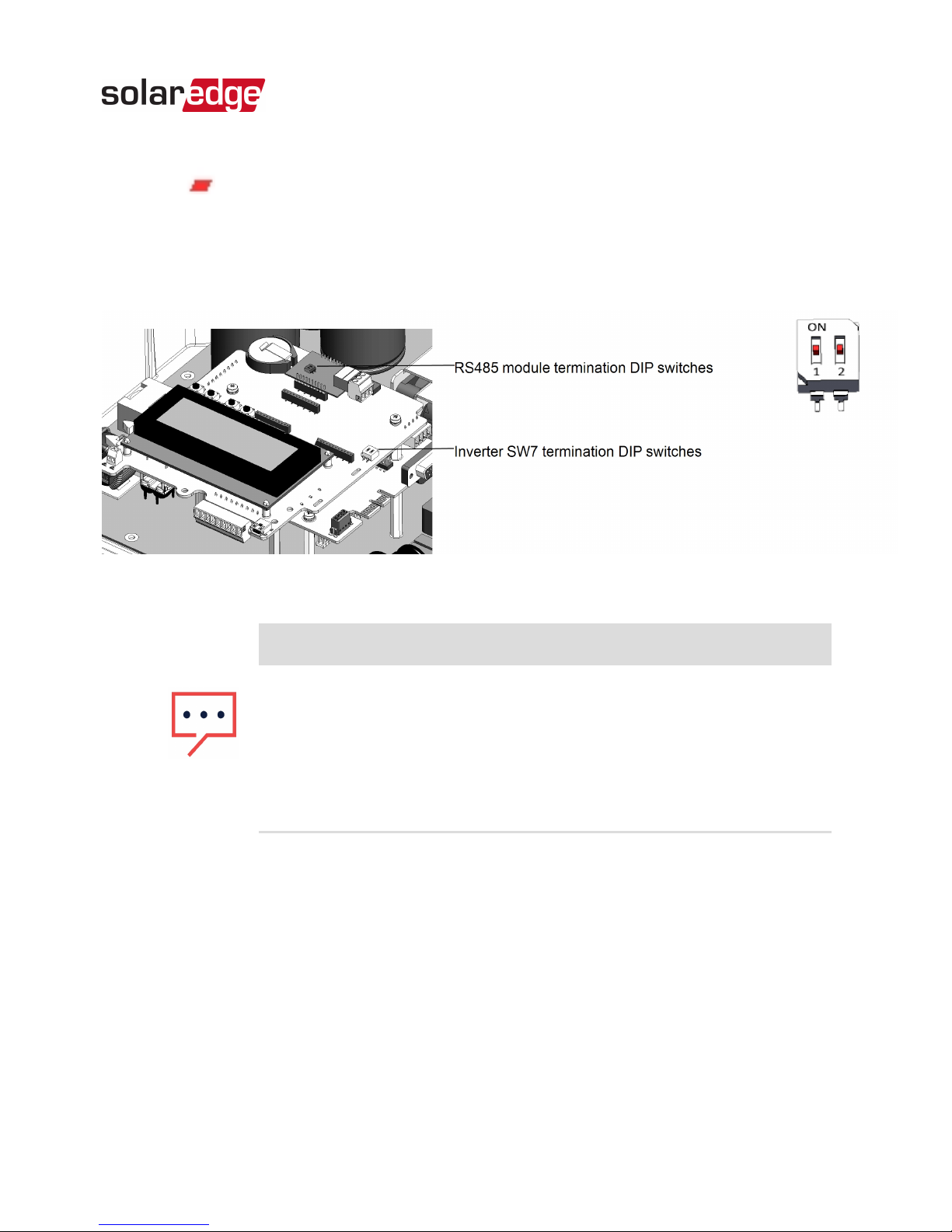
For other devices, the switch located on the
communication board and marked SW7 should be
terminated.
Figure 8: RS485 termination DIP switches
NOTE
Only the first and last SolarEdge devices in the
chain should be terminated. The other devices in
the chain should have the termination switch
OFF (down position).
RS485 Expansion Kit Installation Guide MAN-01-00258-1.0
Chapter 2: Installation 14
Page 16

Installing the Module in the Commercial
Gateway
1.
Remove the Commercial Gatewaycover: Insert a flat
screwdriver into the grooves on the side of the Commercial
Gatewayto release the clasps and carefully remove the
cover.
Figure 9: Removing the Commercial Gatewaycover
2. Pull the two Commercial Gatewayside brackets to release
the LCDboard and access the communication board.
3.
Connect the RS485 module to the socket marked "ZB"on
the communication board. Make sure all the pins are
located correctly in the socket.
RS485 Expansion Kit Installation Guide MAN-01-00258-1.0
15 Installing the RS485 Module
Page 17

Figure 10: Connecting the module to the Commercial Gateway
4. Loosen the screws of pins A(+), B(-), and G on the RS485 3pin terminal block.
5. Insert the wire ends into the G, A and B pins shown above.
Use Four- or six-wire twisted pair cable for this connection.
You can use any color wire for each of the A, B and G
connections, as long as the same color wire is used for all A
pins, the same color for all B pins and the same color for all
G pins.
6.
For creating an RS485 bus - connect all B, A and G pins in
all devices.
NOTE
Do not cross-connect B, A and G wires.
7.
Terminate the first and last device in the chain by switching
a termination DIP switch to ON:
RS485 Expansion Kit Installation Guide MAN-01-00258-1.0
Chapter 2: Installation 16
Page 18
The Commercial Gateway that contains the
expansion module should be terminated by
switching ONthe DIPswitch on the module.
For other devices, the switch located on the
communication board and marked SW7 should be
terminated.
NOTE
Only the first and last SolarEdge devices in the
chain should be terminated. The other inverters
in the chain should have the termination switch
OFF (down position).
8. Carefully return the Commercial GatewayLCDboard to its
location.
9. Carefully re-install the Commercial Gatewaycover.
RS485 Configuration to Master
SolarEdge protocol configuration is supported on all RS485
buses simultaneously. The inverter/Commercial Gateway can
be:
Master on one bus and slave on the other
Master on both buses (dual master)
Slave on both buses
RS485 Expansion Kit Installation Guide MAN-01-00258-1.0
17 RS485 Configuration to Master
Page 19

The RS485 enables the connection of up to 16 RS485 buses
with up to 32 devices each in a daisy chain configuration for
communications in commercial installations.
To configure RS485 communications of the additional
bus:
1. If the master device is an inverter - verify that the inverter
ON/OFF switch is OFF.
2.
Turn ON the AC to the inverter/Commercial Gateway.
WARNING!
ELECTRICAL SHOCK HAZARD. Do not touch
uninsulated wires when the inverter cover is
removed.
3. Press the Enter button for at least 5 seconds, and enter the
password (12312312).
4. Select Communication è Server è RS485.
5.
Select Communication è RS485-E Conf.è Enable. The
following is displayed:
E n a b l i n g R S 4 8 5 - E
I n t e r f a c e . V e r i f y
m o d u l e i s i n s e r t e d .
C o n t i n u e ?
6.
Press Enter to continue. The following is displayed:
RS485 Expansion Kit Installation Guide MAN-01-00258-1.0
Chapter 2: Installation 18
Page 20

D e v i c e T y p e < S E >
P r o t o c o l < S >
D e v i c e I D < 1 >
D i s a b l e
7.
The default protocol is slave. To configure as master select
Protocol è Master.
The Slave Detect and Slave List menus are added to the
screen.
D e v i c e T y p e < S E >
P r o t o c o l < S >
D e v i c e I D < 1 >
S l a v e D e t e c t
S l a v e L i s t
D i s a b l e
8.
Select Slave Detect.
The system starts automatic detection of the SolarEdge
slave devices connected to the master device. The master
device should report the correct number of slaves. If it does
not, refer to the RS485 troubleshooting section below.
Troubleshooting
Troubleshooting RS485 Communication
1. If the message Master Not Found appears, check the
connections to the master device and fix if required.
RS485 Expansion Kit Installation Guide MAN-01-00258-1.0
19 Troubleshooting
Page 21
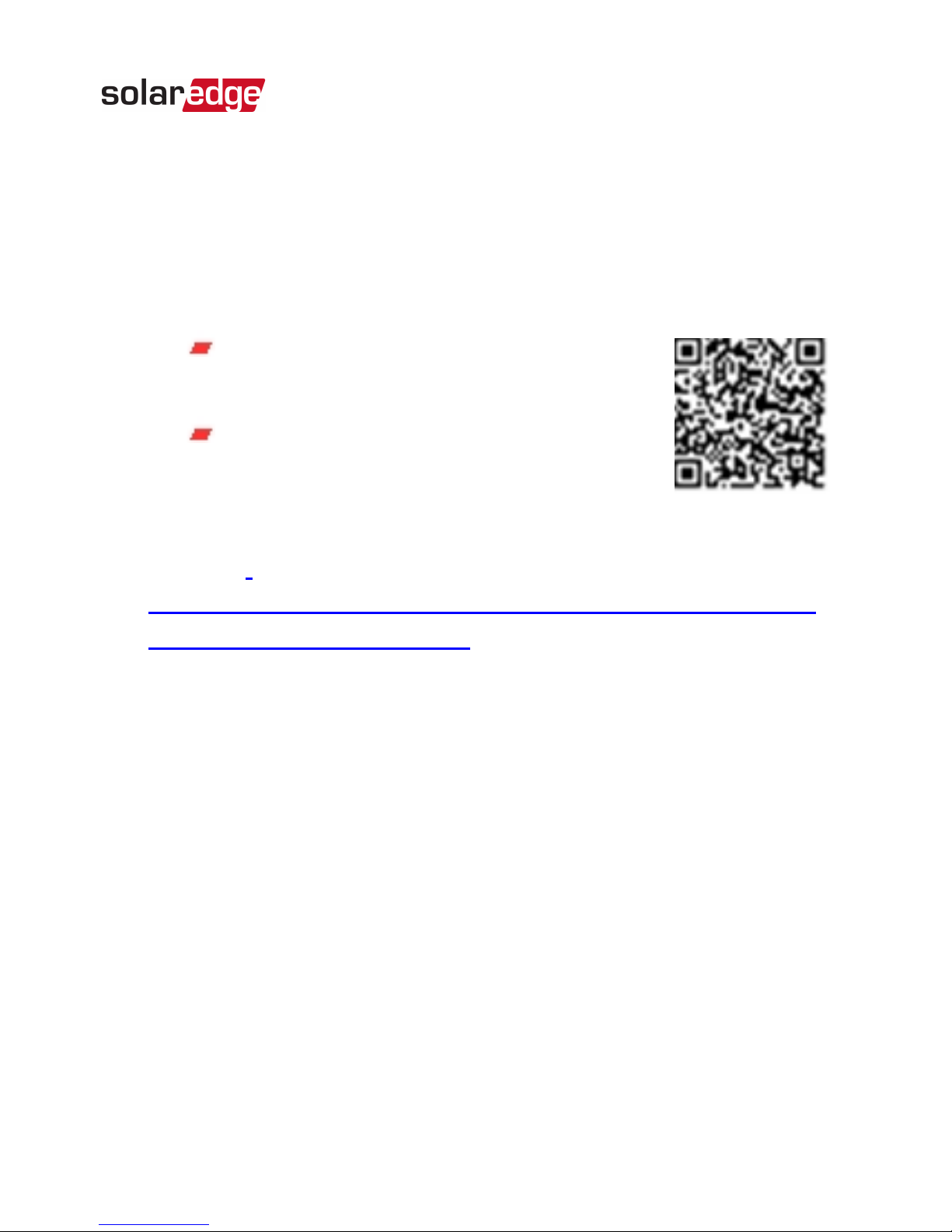
2.
If after slave detection the number of slaves displayed in
the master under RS485-X ConfèSlave Detect is smaller
than the actual number of slaves, use one of the following
methods to identify missing slaves and troubleshoot
connectivity problems:
Use the Long slave Detect to retry
connecting to slaves
Analyze the Slave List to check for
missing slaves, and check their
connection
Refer to
https://www.solaredge.com/sites/default/files/troubleshooting_
undetected_RS485_devices.pdf
RS485 Expansion Kit Installation Guide MAN-01-00258-1.0
Chapter 2: Installation 20
Page 22

Appendix A: RS485 Specifications
FUNCTIONAL Unit
Maximum number of slave
inverters connected on the RS485
bus
31
Maximum number of
interconnected RS485 buses
16
Maximum number of Smart
Energy Management devices on
the RS485 bus
Up to 1 battery;
Up to 2 meters
Maximum RS485 cable length 1000/ 3300 m/ ft
INSTALLATION SPECIFICATIONS
Dimensions (L x W) 33 x 25/ 1.3 x 1 mm/ in
Operating Temperature
-40 to 85/ -40 to
185
°C/°F
RS485 Expansion Kit Installation Guide MAN-01-00258-1.0
21 Appendix A: RS485 Specifications
Page 23

lf you have technical queries concerning our products, please
contact our support through SolarEdge service portal:
www.solaredge.com/service/support
APAC (Asia Pacific)(+972) 073 240 3118
Australia (+61) 1800 465 567
Belgium (+32) 0800-76633
China (+86) 21 6212 5536
DACH & Rest of Europe (+49) 089 454 59730
France (+33) 0800 917410
Greece (+49) 89 454 59730
Israel (+972) 073 240 3122
Italy (+39) 0422 053700
Japan (+81) 03 6262 1223
Middle East &Africa (+972) 073 240 3118
Netherlands (+31) 0800-7105
New Zealand (+64) 0800 144 875
Republic of Ireland 1-800-901-575
South Africa (+27) 0800 982 659
Turkey (+90) 216 706 1929
United Kingdom (+44) 0800 028 1183
US & Canada (+1) 510 498 3200
Worldwide (+972) 073 240 3118
 Loading...