

Solare Datensysteme SolarLog 1000 User Manual


Contents
Chapter 1: Introduction 9
1.1 Standard practice ........................................................................ 10
1.2 Safety Instructions ...................................................................... 10
1.3 Included in delivery ..................................................................... 11
Chapter 2: Installation 13
2.1 Connection options ..................................................................... 13
2.2 Connection to inverter ................................................................... 14
2.3 Terminal block connector ................................................................ 14
2.4 SMA .................................................................................... 15
2.4.1 Note - PiggyBack mixed mode ............................................................ 15
2.4.2 Bluetooth Operation ...................................................................... 15
2.4.3 Special RS485 PiggyBack (Manufacturer: Solare Datensysteme Ltd.) ............ ....... ....... 16
2.4.4 Important Notes for Installation ........................................................... 16
2.4.5 Installation ............................................................................... 17
2.4.5.1 Wiring scheme .............................................................................17
2.4.5.2 Control board without PiggyBack ...........................................................18
2.4.5.3 Control board with PiggyBack ...............................................................18
2.4.6 Original SMA RS485/EIA485 PiggyBack (Manufacturer: SMA) ........... .............. ..... 20
2.5 KACO - Powador / PVI-Blue Planet with RS485/EIA485 interface ....................... 20
2.5.1 Powador ................................................................................. 21
2.5.2 PVI-Blue Planet .......................................................................... 21
2.5.3 Wiring ................................................................................... 21
2.5.4 Terminal block - Powador - Models: ........................................................ 21
2.5.5 Terminal block - PVI-Blue Planet - Models: ................................................. 22
2.6 SolarMax - Series S, C and E with RS485/EIA485 interface ............................... 23
2.6.1 S and C Series ............................................................................ 23
2.6.2 Cx Series ................................................................................ 24
2.6.3 E Series ................................................................................. 24
2.6.4 Wiring ................................................................................... 24
2.7 Fronius - IG 15-60 (HV) and IG 35 + to IG 150+ with ComCard ......................... 25
2.7.1 Installation Fronius ComCard ............................................................. 25
2.7.2 Communication Address .................................................................. 26
2.7.3 Wiring ................................................................................... 26
2.8 Danfoss – Inverters ..................................................................... 27
2.8.1 RS485/EIA485 interface .................................................................. 27
2.8.2 Wiring ................................................................................... 28
2.9 Mitsubishi with RS485/EIA485 interface ................................................. 29
2.9.1 Wiring ................................................................................... 29
2.10 Power-One/Aurora ..................................................................... 29

2.10.1 Terminal block - Outdoor - Models: ........................................................ 30
2.11 Sunways – AT/NT ...................................................................... 30
2.11.1 Terminal strip 750V - Models: ............................................................. 31
2.11.2 Terminal strip 850V - Models: ............................................................. 31
2.12 Vaillant - auroPOWER VPI/1 and VPI (RS485/EIA485) ................................. 31
2.12.1 Vaillant - auroPOWER VPI/1 ............................................................. 32
2.12.2 Vaillant – auroPOWER VPI ............................................................... 32
2.12.3 Wiring ................................................................................... 32
2.13 Solutronic (RS485/EIA485) ............................................................. 34
2.13.1 Wiring ................................................................................... 34
2.14 Schüco SGI Series (RS485/EIA485) ..................................................... 34
2.14.1 Wiring ................................................................................... 35
2.15 REFUSOL .............................................................................. 35
2.15.1 Wiring ................................................................................... 36
2.16 Kostal Pico / Solar-Fabrik Convert T (RS485/EIA485) ........................... ........ 37
2.16.1 Wiring ................................................................................... 37
2.16.2 Multi-String technology ................................................................... 38
2.17 Mastervolt with (RS485/EIA485) ........................................................ 38
2.17.1 Wiring ................................................................................... 38
2.18 Suntension (Sunville) / Phoenixtec (RS485/EIA485) ..................................... 39
2.18.1 Wiring ................................................................................... 39
2.19 Diehl AKO with RS485/EIA485 interface ............................................... 40
2.19.1 Wiring ................................................................................... 40
2.20 Connecting SolarLog1000 Analogue Modem Package ..................................... 41
2.20.1 Included in delivery: SolarLog1000 Modem Package ......................................... 42
2.21 Connecting the SolarLog1000 Mobile Package ............................................ 42
2.21.1 Included in delivery: SolarLog1000 Mobile Package .......................................... 42
2.22 Connecting the MT Sensor Box .......................................................... 42
2.22.1 Assembly ................................................................................ 43
2.22.2 Wiring ................................................................................... 43
2.22.3 Initial startup ............................................................................. 44
2.23 Connecting external electricity meters .................................................... 44
2.24 Attaching large displays .................................................................. 45
2.25 RS485/EIA485 wiring ................................................................... 45
2.26 S0 output wiring ......................................................................... 46
2.26.1 Current controlled S0 output .............................................................. 46
2.26.2 Contact controlled S0 output .............................................................. 46
2.26.3 Pulse factor .............................................................................. 46
2.27 Connecting Relays ....................................................................... 47
2.28 Connecting Alarm contacts .............................................................. 47
2.29 Connection to a PC / Network .......................................................... 48
4

Chapter 3: Manual 49
3.1 Touchscreen Display .................................................................... 49
3.1.1 Menu Structure Touchscreen Display ....................................................... 53
3.2 PC display ........................................................................ ...... 54
3.2.1 Menu structure PC display ............................................................... . 54
3.3 Initial startup ............................................................................ 54
3.3.1 Start configuration ........................................................................ 55
3.3.2 Inverter detection ........................................................................ 56
3.3.3 Inverter Configuration .................................................................... 57
3.4 Display menu navigation ................................................................. 58
3.4.1 Graphic ................................................................................. 58
3.4.1.1 Overview ............................................................ ..................... 58
3.4.1.2 Day graphic ...............................................................................59
3.4.1.3 Month graphic .............................................................................62
3.4.1.4 Year graphic ...............................................................................63
3.4.1.5 Total graphic ..............................................................................64
3.4.2 Diagnosis ................................................................................ 64
3.4.2.1 Messages ..................................................................................64
3.4.2.2 Inverters event log .........................................................................65
3.4.2.3 Alarm contact (anti-theft) ...................................................................66
3.4.3 USB ..................................................................................... 66
3.4.3.1 Copy data .................................................................................66
3.4.3.2 Data backup .......................................................................... .....67
3.4.3.3 Firmware Update ..........................................................................68
3.4.4 Configuration ............................................................................ 68
3.4.4.1 Initial configuration ........................................................................68
3.4.4.2 Inverter detection ..........................................................................70
3.4.4.3 Inverter Configuration ......................................................................71
3.4.4.4 Network Settings ...........................................................................73
3.4.4.4.1 Dialogue 1 – Basic settings ................................................................73
3.4.4.4.2 Dialogue 2 – Network Router ..............................................................74
3.4.4.4.3 Dialogue 3 – Analogue Modem ............................................................74
3.4.4.4.4 Dialogue 4 – GPRS Modem ................................................... ............75
3.4.5 Internet .............................................................................. ... 76
3.4.5.1 Basic settings ..............................................................................76
3.4.5.2 email/SMS ................................................................................76
3.4.5.3 Homepage ................................................................................76
3.4.6 Advanced ................................................................................ 77
3.4.6.1 Plant monitoring ...........................................................................77
3.4.6.2 Large display ..............................................................................77
3.4.6.3 RS485/EIA485 wireless package ............................................................78
3.4.7 Internal .................................................................................. 78
3.4.7.1 System ....................................................................................78
3.5 Configuration via PC .................................................................... 78
3.5.1 Basic Configuration ....................................................................... 79
5

3.5.1.1 LAN - Network Settings ....................................................................79
3.5.1.1.1 Internet access ...........................................................................80
3.5.1.2 Plant groups ............................................................................... 80
3.5.1.3 Inverters order .............................................................................81
3.5.1.4 Inverter ...................................................................................83
3.5.1.4.1 Connected generator power ................................................................83
3.5.1.4.2 Pac correction factor ......................................................................83
3.5.1.4.3 Product label .............................................................................84
3.5.1.4.4 Monitoring ............................................................................... 84
3.5.1.4.5 Graphic Scaling ...........................................................................86
3.5.1.5 Forecast ...................................................................................86
3.5.1.5.1 Plant size ................................................................................87
3.5.1.5.2 Feed-in tariff .............................................................................87
3.5.1.5.3 Annual target .............................................................................87
3.5.1.5.4 Monthly share ............................................................................87
3.5.1.6 Graphic ...................................................................................87
3.5.2 Advanced ................................................................................ 88
3.5.2.1 Internet ...................................................................................88
3.5.2.2 email ......................................................................................89
3.5.2.3 SMS ......................................................................................91
3.5.2.4 Export ....................................................................................93
3.5.2.5 Fault ......................................................................................94
3.5.2.6 Status and error codes of SolarMax inverters .................................................95
3.5.3 Internal .................................................................................. 95
3.5.3.1 Backup ....................................................................................96
3.5.3.1.1 Backup - automatically ....................................................................96
3.5.3.1.2 Backup - manually ........................................................................96
3.5.3.1.3 Data correction ...........................................................................97
3.5.3.1.4 Data import of existing day's data ..........................................................97
3.5.3.2 System ....................................................................................98
3.5.3.2.1 Date/Time ...............................................................................99
3.5.3.2.2 Additional Password Question .............................................................99
3.5.3.3 Update ...................................................................................100
3.6 Homepage ............................................................................. 101
3.6.1 Free Homepage ......................................................................... 102
3.7 Automatic alerts ....................................................................... 102
3.7.1 Inverter failure message - email ........................................................... 102
3.7.2 Inverter failure message - SMS ........................................................... 102
3.7.3 Fault alert from performance monitoring - email ........................................ ... 102
3.7.4 Fault alert from performance monitoring - SMS ................................... ........ 103
3.7.5 Fault alert from status/error code monitoring - email ....................................... 103
3.7.6 Fault alert from status/error code monitoring - SMS ....................................... 103
3.7.7 Alarm notification via alarm contact - email ............................................... 103
3.7.8 Alarm notification via alarm contact – SMS ................................................ 103
3.7.9 Yield overview – email .................................................................. 104
3.7.10 Yield overview – SMS ................................................................... 104
6

3.8 Yield data .............................................................................. 104
3.8.1 PC Visualization ........................................................................ 105
3.8.1.1 Daily overview ............................................................................105
3.8.1.2 Monthly overview .........................................................................107
3.8.1.3 Yearly overview ...........................................................................108
3.8.1.4 Total overview ............................................................................109
3.9 Diagnosis .............................................................................. 111
3.9.1 Event log ............................................................................... 111
3.10 Dial-in using an Analogue Modem ...................................................... 113
3.11 Useful software ........................................................................ 116
3.11.1 Printing ................................................................................ 117
3.12 LED status display ..................................................................... 117
3.13 Reset button ........................................................................... 118
Chapter 4: Technical Data 119
4.1 Internet ports .......................................................................... 119
4.2 Timer ................................................................................. 120
4.3 Activity log ............................................................................ 120
4.4 CE Declaration of Conformity ......................................................... 121
7


1 Introduction
The SolarLog1000 represents the latest generation of the SolarLog series. Building on the web
technology of previous devices, there have been many wishes and suggestions consistently implemented into this device.
The modern display with touchscreen and extensive connectivity options open up unprecedented
possibilities. The new case design is not only aesthetically pleasing but also very practical. This
allows all the cables to be kept hidden and at best completely invisible to the rear.
The SolarLog1000 is a device that can support a variety of inverters supported by its two data
interfaces. Environmental data such as sunlight radiation and temperatures, even wind measurements can be recorded. The data can be loaded onto a USB stick and graphically analysed later
on a PC.
The integrated S0 pulse counter connection can connect digital electricity meters and hence measure electricity consumption. The SolarLog then automatically calculates an energy balance, offsetting its own electricity consumption.
Last but not least, the SolarLog1000 can attach large displays, through the S0 pulse output, or parallel to the inverter via the RS485/EIA485 interface.
The Bluetooth module is optionally available with the SolarLog1000 and can connect the latest
generation of SMA inverters wirelessly.
All these capabilities go to help ensure your photovoltaic system achieves the desired yield for a
long time and problems can be quickly identified and resolved.
In this sense, we wish you every success working with the SolarLog1000 with many profitable
and sunny days.
9

1 Introduction
1.1 Standard practice
The manual consists of 2 parts. First, the installation process is described, i.e. the assembly of the
SolarLogs and the wiring of the inverter to the SolarLog. Then follows the user's manual in
which the configuration and further operation will be described in detail.
Please get to know the device before installing anything. Especially during the initial
installation you should take some time to go through the manual - and not simply just "go
for it".
1.2 Safety Instructions
Read first prior to startup, the following safety instructions.
Our products leave the factory in perfect condition.
In order to maintain this condition, care must be taken in dealing with the equipment (transport,
storage, installation, startup, operation, maintenance, taking out of service). These safety instructions, model plates, labels and safety precautions must be observed, otherwise it can endanger
people's lives and the product itself, and other installations can be damaged.
These safety precautions apply in the Federal Republic of Germany. When used in other countries the relevant national regulations apply.
If the information with these safety precautions should not be sufficient, you can contact the
manufacturer at the given address at any time.
Please check the packaging and claim any damages immediately with the delivery company.
Make sure before turning on, that the power adapter has no damages. If in doubt, consult an
electrician or get in touch with the address at the end of this manual.
Before turning on, please make sure the voltage of the device is identical with the mains supply
in your country.
The device may only be operated with the included power adapter.
If the power adapter comes directly out of a cold environment to a warm environment, condensation may occur. Wait until the temperature compensation has taken place. To start the
device without the temperature compensation is life-threatening!
Repairs should only be performed by authorized personnel. Please contact the mentioned
address at end of the manual.
The power adapter should be checked regularly for damage. In the case of damage to the power
adapter, it needs to be immediately taken out of service and replaced.
10

The device is not suitable for outdoor use
Before cleaning: unplug the device! For cleaning use a gentle detergent with a damp cloth. Never
clean when dripping wet!
Other notes:
The SolarLog1000 operates on 12Volt DC (12VDC, max. 24VDC). Running the unit on a different voltage will invalidate the warranty. Please use only the enclosed power adapter.
The SolarLog1000 has IP20 standard protection and is designed exclusively for installation in dry,
dust-free interiors.
The relay can be used with maximum 24VoltDC and loaded to 5A.
Before any cable connection between the SolarLog1000 and inverter is made, the inverters must
be without any power. That means the AC side must first be separated, then the DC-side. Then
wait at least 5 minutes until the capacitors in the inverters have discharged.
1.3 Included in delivery
The SolarLog1000 is delivered with the following components:
1.SolarLog1000 – Basic Unit
2.12Volt Power adapter
3.Manual
4.Terminal block connectors for all connections: (except CAN): 2x 3-pin, 1x 4-pin, 2x 6-pin
5.4x wall plugs (dowels) and screws for wall mounting
For connection to a PC or network you need a network cable (RJ45 CAT5 or CAT6) in the corresponding length.
Furthermore, you will need suitable cable material for the wiring of the inverters to each other.
Optionally available are suitable, prefabricated cable-sets for the respective inverter manufacturers. The cables have a length of 3m.
11


2 Installation
he installation of the SolarLog1000 must take place indoors and protected from dust. For
outdoor and dusty environments, the SolarLog needs to have appropriate protective hous-
T
of the two housing shells top and bottom.
2.1 Connection options
ing.
The assembly is via 4 mounting points on the rear of the housing. This requires the removal
The SolarLog1000 has extensive connections at the housing bottom and top.
Bottom:
Relay Relay, for switching external signals. For example rotating flashing beacon/light, etc.
RS485-A First RS485/EIA485 interface. Connection to inverter, Sensor Box or large display
(inactive, when the optional Bluetooth interface is in use)
RS485/RS422-BSecond RS485 interface (RS422 for Fronius/Phoenixtec). Connection to inverter,
Sensor Box or large display
Power 12V 12 Volt DC voltage input (max. 24VDC)
Network Ethernet network interface, 10/100 MBit
RS232/EIA232 RS232/EIA232 Modem Interface Connecting an analogue or GPRS Modem
Top side:
S0 In/Out S0 pulse input for connection to external electricity meter. S0 pulse output for connec-
tion to external large display
13
2 Installation
Alarm Contact loop for connection to anti-theft device. With optical cables transfers up to
5km.
CAN CAN bus, for future extensions. Currently unused. No terminal strip is included for
this socket.
USB USB host connection. Suitable for USB sticks up to 2GByte capacity (Warning: Not
suitable for connecting to PCs!)
Reset Reset button. Multi-function: 1. Restart SolarLog, 2. Reset to factory settings
2.2 Connection to inverter
Since the SolarLog1000 communicates directly with each inverter, the appropriate data cable is
required. For the connection of SolarLog1000 to the first inverter there are green terminal block
connectors.
Note: pre-assembled cable sets, suitable for your inverter, are available as accessories.
Since each inverter manufacturer uses different wiring and connections, you must have the relevant data cable connected correctly. The following chapters describe the manufacturer supported
connection configurations.
Note: It is essential that you follow the instructions from the manufacturer for connecting the
data cables. These instructions can be taken from the appropriate manufacturer's documentation.
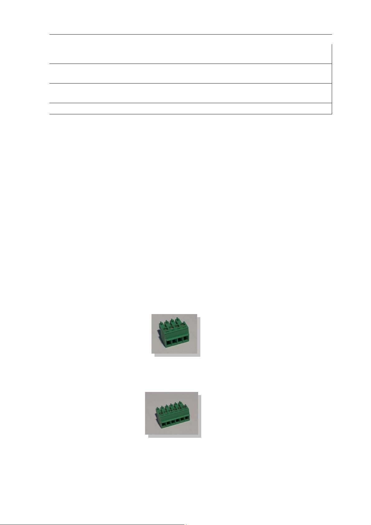
2.3 Terminal block connector
The SolarLog1000 has 2 RS485/EIA485 interfaces, each marked by "A" and "B". The "B" interface can also be used as a RS422 interface (for Fronius/Phoenixtec inverters).
RS485 A: 4-pin green connector
1 4
RS485/RS422-B: 6-pin green connector
1 4 6
The numbering of the connecting plugs are from left to right, from 1 to 4 and 6.
14

The assignment of the connectors are as follows:
Pin RS485-A RS485-B RS422 (for Fronius/Phoenixtec)
1 Data+ Data+ T/RX+
2 12V 12V 12V
3 Earth Earth Earth
4 Data- Data- T/RX5 R/TX+
6 R/TX-
Note: The term "data+" / "data-" is manufacturer specific. Sometimes "A" and "B"
are used/described here, or other combinations. Please adhere exactly to the description in
this manual, otherwise the inverter will not be detected!
2.4 SMA
Please note: For SMA inverters there are
2 different connection options
into the inverter.
, depending on which RS485-PiggyBack is built
Careful! - different wiring!
Original SMA RS485 PiggyBack: 3-pin Wiring
Special RS485 PiggyBack: 4-pin Wiring
Both PiggyBacks can be fully integrated and installed into all SMA inverters of type "SunnyBoy"
(exception: SB3000/4000/5000TL-20 Next Generation) or of type "Sunny Mini Central".
Important note: Never open the casing of the inverter if it is live. Observe strictly the instructions in the SMA manual.
2.4.1 Note - PiggyBack mixed mode
The special RS485 PiggyBack can also be used in mixed mode with the original SMA PiggyBack
modules. They must also have a 4-wire cabling in place. However, never connect clamp 2 (yellow
SolarLog) with clamp 3 (inverter with Original-PiggyBack/Data Module)
2.4.2 Bluetooth Operation
Note:
1.The Bluetooth operation is only possible when the optional Bluetooth module is installed on
SolarLog1000.
15

2 Installation
2.Currently only inverters SMA-SB3000/4000/5000-20 support wireless Bluetooth operation
(May 2009)
For the Bluetooth operation, there's no preparation necessary on the inverter. The SolarLog1000
currently can read a maximum of 7 Bluetooth SMA inverters
The detection should take place in the same room as where the inverter is. This will stop detection failures due to lack of range. Afterwards, you can then test the SolarLog even further away
from the inverter. Signal strength display is unfortunately not possible.
2.4.3 Special RS485 PiggyBack (Manufacturer: Solare Datensysteme Ltd.)
Note: Here a 4-pin wiring is needed!
The special PiggyBack is a simple RS485 interface converter without controller or without its
own "intelligence". Through the simple and robust design, disturbance behaviour on the inverter
is eliminated. When correctly installed and in compliance with the installation requirements, the
technical data and properties of the inverter remain unchanged. The PiggyBack is galvanically
isolated and has a 6.5 kV isolation protection. Each PiggyBack runs individually a complete functional test on the SMA Inverter.
Note: The Special PiggyBack may only be combined and operated with the SolarLog1000.
The Special RS485 Piggy-backs are compatible with inverters of type
−SB-SunnyBoy (but not to the SB-3000/4000/5000TL-20 NextGeneration, here the original
SMA RS485 Data module must be used)
−SMC SunnyMiniCentral
−SWR inverter (built from 2001 onwards). Possibly the display needs to be dismantled to add-on
the PiggyBacks. This "space problem" exists also on the original SMA PiggyBack.
Please check the completeness of the supplied accessories:
1x isolation tube for data cable
1x Jumper
1x screw connection/feed through Inverter-PG 16 (M22)
1x flat power distributor for connection to housing/earth
2.4.4 Important Notes for Installation
For the fitting of PiggyBack interface cards, the inverter must be opened. This may only be carried out by trained professionals. You should also read all the instructions of the available
inverter manual.
16
2.4.5 Installation
Jumper
set
Insulating
Special
PiggyBack
Work on the inverter must carried out exclusively with a separate power supply. First disconnect
the inverter on the AC side, then from the DC side. Then wait 30 minutes until all the live parts
are discharged.
Also, please note that in the inverter and on the interface card are sensitive electronic components which can be destroyed by static discharge.
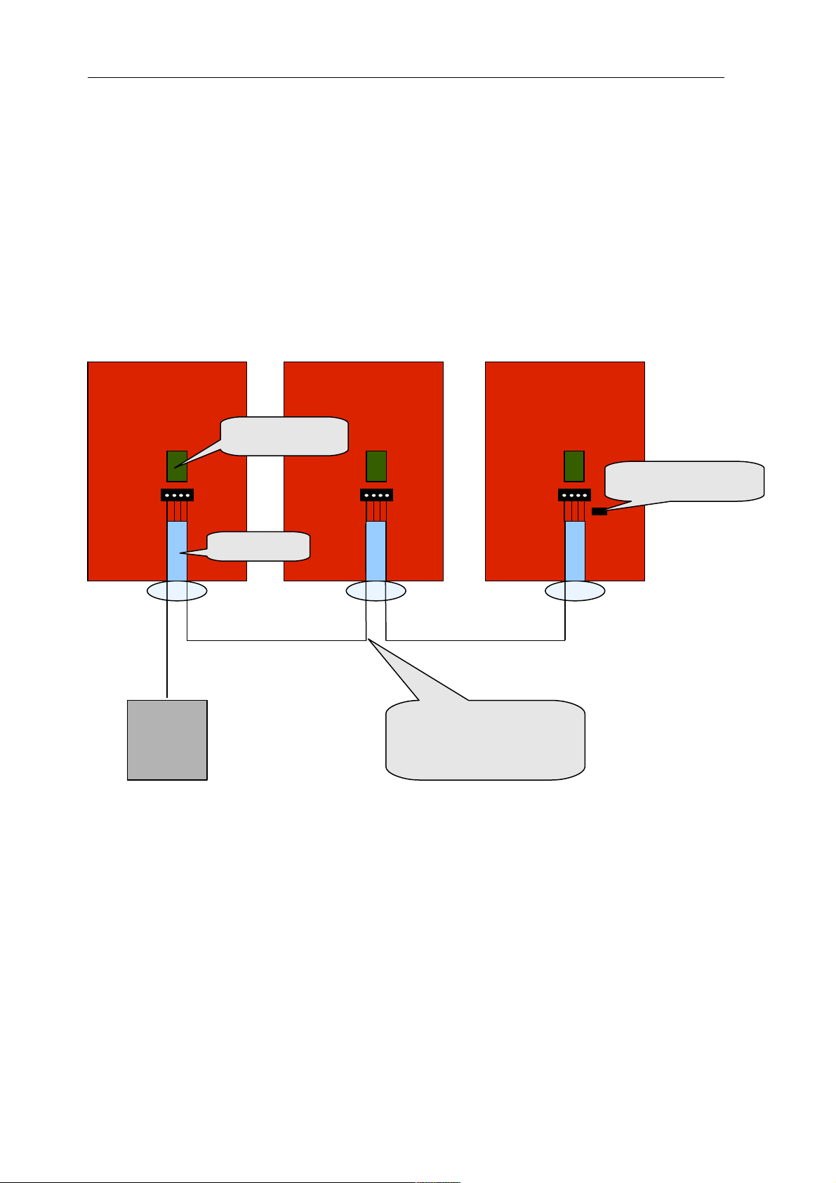
2.4.5.1 Wiring scheme
SMA Inverter 2SMA Inverter 1 SMA-Inverter x
SolarLog
4-wire, shielded
Cable
Step 1
Insert first the PiggyBack on the control board in the inverter. Make sure the word "below" is
visible on the bottom left side of the control board (see Figure 2 below). Note: The lower pin
row must be aligned left.
17
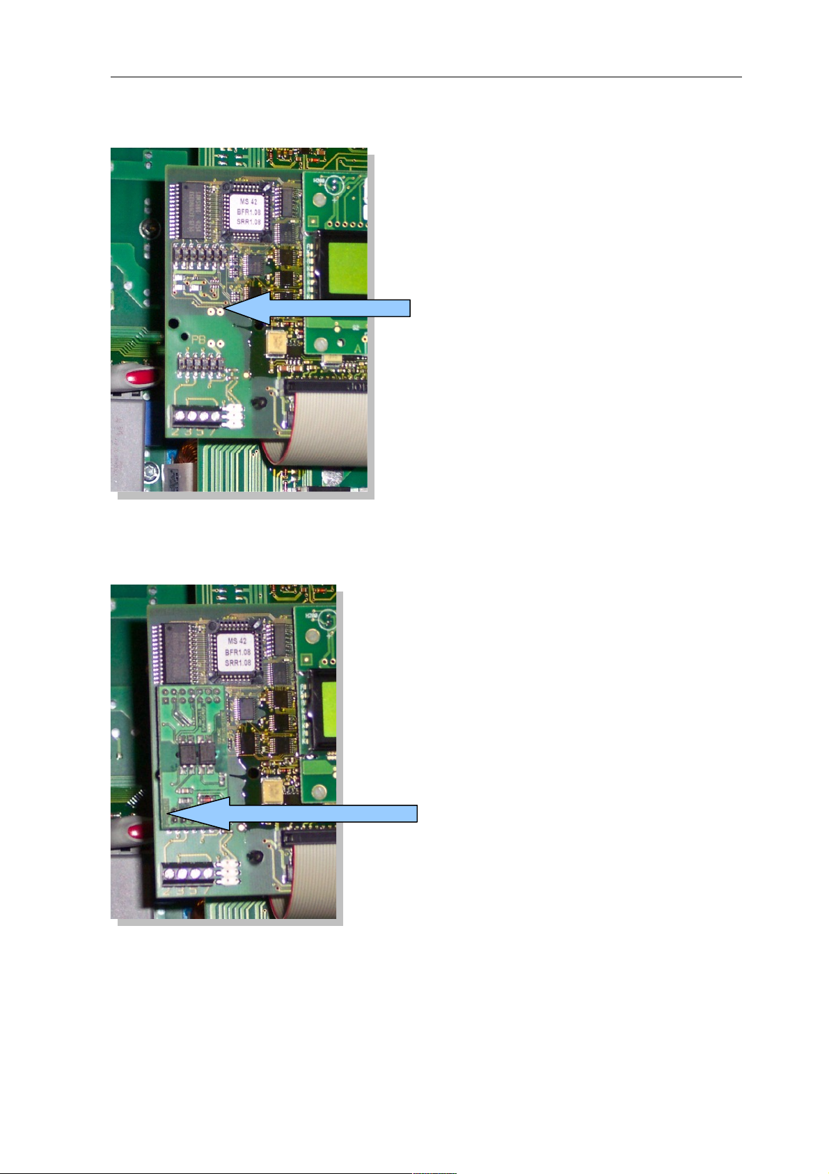
2.4.5.2 Control board without PiggyBack
2 Installation
This is
where the
PiggyBack is
attached
2.4.5.3 Control board with PiggyBack
Label:
Below
Step 2
Now the individual inverters must be wired to one another. You need a 4-pin, shielded data cable
(e.g. 25m ring, Solare Datensysteme order no. 220014). Connect each of the 4 contacts (2,3,5,7)
on the terminal block of inverter 1 to inverter 2 and inverter to 3, etc. until you have connected
all inverters.
18

In older SMA inverters of type SWR there's possibly a 10-pin terminal block strip available. Con-
Terminal
block strip
Contacts
nect here also the contacts 2,3,5 and 7 and leave the others free.
Please make sure that the data cable in the interior of the inverter is fed through the silicone
insulation strips.
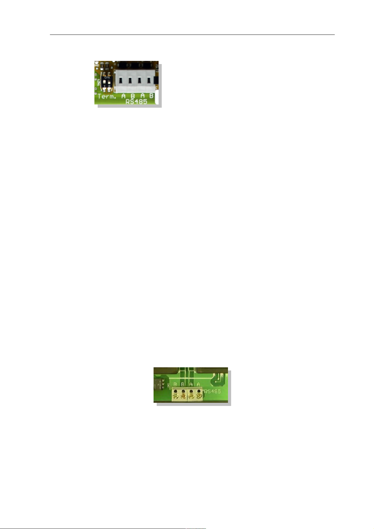
Step 3
A terminating resistor has to be set on the last inverter. Set the jumper to the lowest position:
Jumper set
(bottom)
The middle and upper position must remain free!
Step 4
Now you need connect the first inverters per cable with the SolarLog.
For the connection of SolarLog with the first inverter you can use either a prefabricated data
cable (not included) or your own cable.
19

2 Installation
Pull the exposed wires through the cable opening of the inverter and connect them
SolarLog Terminal strip in the inverter
White (1) 2
Yellow (2) 3
Green (3) 5
Brown (4) 7
Pull the data cable through the enclosed insulation tube. Connect terminal strip 5 of the inverter
with the accompanying flat pin on the inverter casing.
This completes the hardware installation. You can close the inverter and turn it on.
2.4.6 Original SMA RS485/EIA485 PiggyBack (Manufacturer: SMA)
Note: A 3-pin
wiring
is required!
The installation is very detailed in the SMA PiggyBack manual, enclosed with the interface board.
The wiring of the inverters with one another is described on page "6 from 8" under "Wiring a
SB/SWR via RS485 to a PC". Connect each individual inverter as in the SMA manual with a
shielded 3-pin data cable.
Then you set jumper A on the PiggyBack of the last inverter as shown on page "5 of 8" and "6
of 8" in the SMA's manual.
For the connection of the SolarLog with the first inverter you can use either a prefabricated data
cable (accessories not included) or your own cable.
Pull the exposed wires through the cable opening of the inverter and connect them
SolarLog Terminal strip in the inverter
White (1) 2
Green (3) 5
Brown (4) 7
Pull the data cable through the enclosed insulation tube. Connect terminal strip 5 of the inverter
with the accompanying flat pin on the inverter casing.
This completes the hardware installation. You can close the inverter and turn it on.
2.5 KACO - Powador / PVI-Blue Planet with RS485/EIA485 interface
Important note: Never open the casing of the inverter if it is live. Observe strictly the instructions in the KACO manual.
20

2.5.1 Powador
All Powador models have the RS485 interface already integrated from the factory. The interface
must be activated through the operating display. Additionally, each inverter needs a separate communication address assigned to it. It is advisable for the addresses to start at 1, i.e. 1, 2, 3, etc.
Again, this setting will be carried out via the operation display. Follow the instructions in the
KACO manual.
The KACO-Central Inverters are shown as 3 separate inverters in the SolarLog. If for example
two central inverters are available and assigned with address 1 and 2 per RS485 interface, that
would give a total of 6 inverters showing up in the SolarLog.
2.5.2 PVI-Blue Planet
The PVI-BluePlanet models were shipped up to the middle of 2005 and shipped from the factory with an optional RS232 or RS485 fitted. To operate with the SolarLog1000 the RS485 option
is absolutely necessary. The changing of the interface is possible via the Kaco company. Please
ask your installer about this, or KACO directly.
Each inverter needs to have a separate communication address assigned to it. Assignment is
made via a DIP switch inside the inverter. Follow the instructions in the KACO manual. It is
advisable for the addresses to start at 0, i.e. 0, 1, 2, 3, etc.
Note: If the DIP switch is missing on the control board, then it's the RS233 version of the PVIBlue Planet inverter.
2.5.3 Wiring
The wiring of each inverter is carried out by terminal strips that are placed and located inside the
device.
2.5.4 Terminal block - Powador - Models:
Powador built prior to 2006/2007
21
2 Installation
Powador from 2006/2007 onwards (Termination via DIP switches)
Powador 8000xi (6400xi/7200xi):
The 8000xi models are interesting from a cabling side, because here, three 8000xi can be combined together in a group. Similarly, it is also possible to use 1 or 2 devices without grouping
them. The wiring is always completely different. Detailed instructions can also be found in the
Installation manual for KACO inverters.
8000xi as a group:
•Here, one of the three inverters is set per jumper as the "Master" whereas the other two act as a
"slave". Warning! A set jumper ALWAYS means "Slave", pulled jumper ALWAYS "Master" regardless of the labelling on the motherboard. That means, on the master inverter, the jumper
should be pulled, the two slaves must have the jumper set.
•The data cable of the SolarLog will be attached to the terminal strip "LOGGER" of the "Mas-
ter" inverter
•The 3 inverters are also connected amongst each other via the terminal strip "SYM" .
•All 3 inverters must be equipped with a sequential RS485/EIN485 address which can be con-
figured via the display on the inverter.
•„SYM-Bus" needs to be turned to active on the display of the inverter
8000xi separately:
•Inverter changed to "Slave", i.e. the jumper has to be set.
•The data cable of SolarLog will be attached to the terminal strip "SYM" of the "slave" inverter
•All inverters must be equipped with a sequential RS485/EIN485 address which can be con-
figured via the display on the inverter.
•„SYM-Bus“ needs to be turned to inactive in the configuration on the display of the inverter
2.5.5 Terminal block - PVI-Blue Planet - Models:
Connect each inverter with each other as in the Kaco manual with a shielded 2-pin data cable via
the RS485 terminal strips. There are two RS485 ports, so that the wiring can be passed through.
Connect each terminal A with terminal A of the next inverter and accordingly with the terminals
B.
22

For the connection of the SolarLog with the first inverter, one can use either a prefabricated data
cable (accessories not included) or your own cable.
Pull the exposed wires through the cable opening of the inverter and connect them
SolarLog Terminal strip in the inverter
White (1) B
Brown (4) A
BluePlanet / Series 1- Powador:
In addition, a terminating resistor with 330Ohm (enclosed with inverter) needs to be set at the
terminal block on the inverter furthest from the SolarLog. The terminating resistor connects the
free terminal A with terminal B.
Series 2-Powador:
In addition, a terminating resistor on the internal DIP switch (see picture above) to the furthest
inverter from the SolarLog must be set. Please take care to switch DIP switches from the other
inverters to "Off", otherwise it won't be possible to have correct data communication.
Note: If the cable lengths are kept relatively short, the terminating resistor may be omitted in certain circumstances.
2.6 SolarMax - Series S, C and E with RS485/EIA485 interface
Important note: Never open the casing of the inverter if it is live. Observe strictly the instructions of the Sputnik/SolarMax manual.
2.6.1 S and C Series
All the S/C models have the RS485 interface already integrated from the factory. Each inverter
needs to have a separate communication address assigned to it. It is advisable for the addresses to
start at 1, i.e. 1, 2, 3, etc. Again, this setting will be carried out via the operation display. Follow
the appropriate instructions in the SolarMax manual.
S Series: See to it on the inverter's display that only the RS485 interface is enabled (factory
default), and not the built-in Ethernet interface.
Note: The factory default address setting of the inverter is 255, which is not a valid address number. Therefore, even if only 1 inverter is attached to the SolarLog, the address has to be set
manually to "1".
23

2 Installation
2.6.2 Cx Series
The Cx-series models do not contain any RS485 interfaces and need to be retrofitted. Please contact in this case the installer or manufacturer.
2.6.3 E Series
The E-series models have no communication interfaces, which means an interface has be fitted
before being able to attach to the SolarLog.
Please follow the installation instructions that are attached to the relevant interface. Pay particular
attention to the proper setting of the RS485/RS232 Jumpers and the terminating resistance on
the interface card (See manual of the interface card).
Each inverter needs to have a separate communication address assigned to it. It is advisable for
the addresses to start at 1, i.e. 1, 2, 3, etc. Again, this setting will be carried out via the operation
display. Follow the appropriate instructions in the SolarMax manual.
2.6.4 Wiring
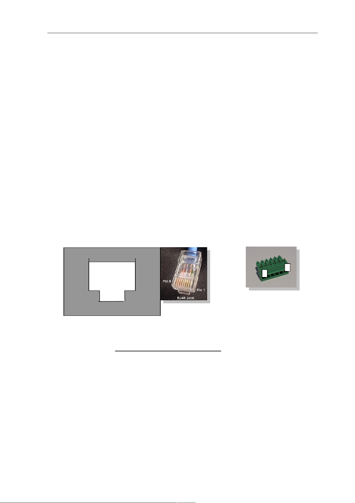
Use the RJ45 format for attaching and connecting the RS485 data cable plug to the inverter.
These are the same plugs as in conventional network patch cables.
Warning! The SolarLog also has an RJ45 socket. Please under no circumstances connect this
socket to the RJ45 socket of the inverter. This could destroy the SolarLog!
Note: We recommend the prefabricated SolarMax data cable, which is available as an accessory.
If the cable is custom-made, then use the following termination circuit:
18
RJ45-plug from the front
RJ45 Pin SolarLog RS485
1 2
2 2
3 3
4 3
5-unused
6-unused
7 1
8 4
24

The wiring of each inverter to each other is carried out with conventional network cable, with a
RJ45 plug fitted.
SolarMax S/C Series:
The wiring can be done at anytime because the inverter doesn't have to be opened.
At the bottom of the device you'll find the two RJ45 connectors for plant communication. Insert
the plug of the cable into any socket on the first inverter. The other plug of the cable can be
inserted into any socket on the second inverter. That's how to connect inverter number 2 with
inverter number 3, etc.
Attach the last inverter with the last free jack to the SolarLog using the prefabricated SolarLog
data cable with the RJ45 plug.
SolarMax E Series:
Turn off the electricity or wait till evening (the entries on the display for setting the communication address needs to happen during daytime)
Since the RJ45 connector sockets are on the inside of the inverter on the interface card, the network cable needs to be threaded through the cable feed-through at the bottom of the device.
Except for the first inverter, you always feed two cables: One cable from the previous inverter
and one cable to the next inverter or to the SolarLog. Plug the cable from the previous inverter
from the left socket with the inscription "RS485 in" to the cable on the next inverter in the right
socket with the inscription "RS485 out".
Attach the last inverter with the last free jack to the SolarLog using the prefabricated SolarLog
data cable with the RJ45 plug.
2.7 Fronius - IG 15-60 (HV) and IG 35 + to IG 150+ with ComCard
Important note: Never open the casing of the inverter if it is live. Strictly observe the instructions in the Fronius manual.
Before the SolarLog1000 can be connected to the inverter, an interface board called a „ComCard“ needs to be installed.
2.7.1 Installation Fronius ComCard
The ComCard can come installed from the factory on the inverter or a ComCard can be installed
later on as a retrofit.
Note:The inverter must be opened for the fitting. Please follow strictly the guidelines of the
Fronius IG manual with your inverter!
The installation of the ComCard is very detailed in the inverter manual, follow all the instructions there.
We recommend to leave a free slot between the installed ENS card and ComCard.
25
2 Installation
2.7.2 Communication Address
Each inverter needs to have a separate communication address assigned to it. It is advisable for
the addresses to start at 1, i.e. 1, 2, 3, etc. Again, this setting will be carried out via the operating
display. Follow the instructions in the Fronius manual from the chapter "Operational concept",
section "setup Menu".
2.7.3 Wiring
The wiring of each inverter to each other is carried out with conventional network cable, with a
RJ45 plug fitted.
Each ComCard has two RJ45 jacks, each with "IN" and "OUT" marked. It is very important to
adhere to the right order with the cabling, otherwise no data exchange can take place.
Warning! The SolarLog also has an RJ45 jack. Please under no circumstances connect this jack to
the RJ45 socket of the inverter. This could destroy the SolarLog!
As Fronius can use a RS422 interface, only use the 6-pin RS422 B connection with the SolarLog.
Note: We recommend the prefabricated Fronius data cable, which is available as an accessory.
The cable set includes a terminating plug (which has no terminal resistance!)
If the cable is custom-made, then use the following termination circuit:
RS422 B:
18
6
1
RJ45-plug from the front
RJ45 Pin SolarLog RS422 B (6. pin)
1 2 3 5
4 1
5 4
6 6
7 8 -
26

Terminating plug:
The terminating plug consists of an 8-pin RJ45 blind plug, in which the following wires are
bridged:
RJ45 PIN bridged
3 and 4
5 and 6
over the prefabricated cable with the 6-pin, connect now the SolarLog RS422 B with the IN jack
of the first inverter.
Then connect all inverters via Inverter-1 OUT with Inverter-2 IN, Inverter-2 OUT with
Inverter-3 IN etc.
In the OUT jack of the last inverter plug in the termination plug.
Note: The LED-E on the SolarLog shows the communication status. As soon as all cables are
correctly plugged in and all inverters are active, the red LED turns off.
2.8 Danfoss – Inverters
Important note: Never open the casing of the inverter if it is live. Observe strictly the instructions in the Danfoss manual.
The company Danfoss (PowerLynx) produces also for other manufacturers, e.g. for IBC (ServeMaster) or CentroSolar (Powerstocc®) or in the past for Kyocera (KCx) and SolarWorld (Sun-
Plug).
These devices are largely identical and use the same data protocol.
The interfaces could however deviate.
The SolarLog supports all devices from the company Danfoss
1.UniLynx
2.TripleLynx
2.8.1 RS485/EIA485 interface
A RS485/EIN485 interface is required for monitoring data with the SolarLog. This interface for
UniLynx inverters from February/2007 onwards is already built in from the factory. Previous
models were delivered equipped with either RS485 or a wireless interface. The wireless interface
can't be used with the SolarLog. In this case, the RS485 interface needs to be retrofitted by a
Solar Engineer.
All TripleLynx models have the RS485 interface already built in.
Additional settings on the display are not necessary.
If the TripleLynx devices have an internal modem (e.g. GSM) installed, this must be
disabled, otherwise the RS485 interface of the inverter is inactive! Please contact your
inverter supplier concerning this.
27

2 Installation
2.8.2 Wiring
The wiring of each inverter to each other is carried out with conventional network cable, with a
RJ45 plug fitted. The two RJ45 jacks are located on the right side of the inside cover, which can
be screwed off. Please follow the instructions for that in the Danfoss manual.
Then connect all inverters with each other via conventional network cable.
Insert the plug of the cable into any socket on the first inverter. The other plug of the cable can
be inserted into any socket on the second inverter. That's how to connect inverter number 2 with
inverter number 3, etc.
On the free jack of the first inverter, plug in either the Danfoss data cable (accessories not
included) with the RJ45 connector or the self-assembled cable.
Plug the terminating plug into the last free socket on the last inverter.
Danfoss/PowerLynx wiring:
RS485:
18
RJ45-plug from the front
RJ45 Pin SolarLog RS485
1 3
2 3
3 4
4-unused
5-unused
6 1
7-unused
8-unused
Terminating plug:
The terminating plug consists of an 8-pin RJ45 blind plug, in which the following wires are
bridged:
RJ45 PIN bridged
3 and 4
5 and 6
28

2.9 Mitsubishi with RS485/EIA485 interface
Important note: Never open the casing of the inverter if it is live. Observe strictly the instructions in the Mitsubishi manual.
All inverters from Mitsubishi have the RS485 interface already integrated from the factory. Additionally, each inverter needs a separate communication address assigned to it. It is advisable for
the addresses to start at 1, i.e. 1, 2, 3, etc. Again, this setting will be carried out via the operating
display. Observe the instructions in the Mitsubishi manual. (The address number 1 is the default
for all Mitsubishi inverters)
2.9.1 Wiring
The wiring of each inverter to each other is performed by conventional telephone cable, with an
RJ11 plug fitted. RJ11 connectors are normally 6-pin, but only the middle 4 pins are used, which
are sufficient. It is important that the 4 (or 6) Pins are looped through 1 to 1.
Both RJ11 jacks are located bottom left on the inside of the inverter. For the installation, the
front panel of the inverter has to be removed. Please follow the instructions for that in the Mitsubishi manual.
Connect now all inverters with each other via the RJ11 cable.
Insert the plug of the cable into any socket on the first inverter. The other plug of the cable can
be inserted into any socket on the second inverter. That's how to connect inverter number 2 with
inverter number 3, etc. On the last inverter set the DIP switch for the terminating resistor to position "on".
For the connection of the SolarLog with the first inverter you can use either a prefabricated data
cable (accessories not included) or a separate cable manufactured to the following requirements:
Mitsubishi Wiring:
RS485:
RJ11 Pin SolarLog
3 1
4 4
2.10 Power-One/Aurora
Important note: Never open the casing of the inverter if it is live. Observe strictly the instructions in the Power-One manual.
29
2 Installation
All inverters from Power-One have the RS485 interface already integrated from the factory.
Additionally, each inverter needs a separate communication address assigned to it. It is advisable
for the addresses to start at 2 (not 1), i.e. 2, 3, 4, etc. Again, this setting will be carried out on the
display. Follow the instructions in the Power-One/Aurora manual
Wiring
The wiring of each inverter is carried out by terminal strips that are placed and located inside the
device. Sometimes different interfaces are installed for indoor/outdoor models. The following is
a guide to wiring with RS485.
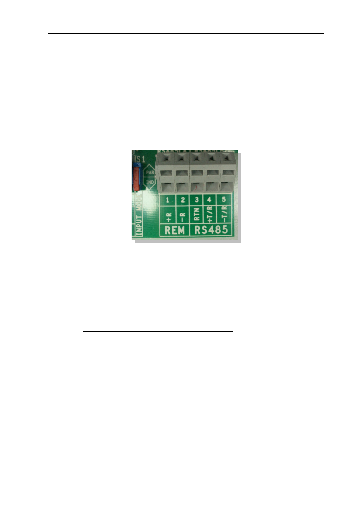
2.10.1 Terminal block - Outdoor - Models:
Connect each inverter with each other as described in the inverter manual with a shielded 3-pin
data cable via the RS485 terminal strips. Connect each terminal "+T/R" with terminal "+T/R"
to the next inverter and the terminals "T/R" and "RTN".
For the connection of the SolarLog to the first inverter you can use either a prefabricated data
cable (accessories not included) or your own cable.
Pull the exposed wires through the cable opening of the inverter and connect them
SolarLog Terminal strip in the inverter
White (1) +T/R
Brown (4) -T/R
Green (3) RTN
In addition, the terminating resistor on the inverter furthest from the SolarLog must be set. The
small switch must be set to position "ON".
2.11 Sunways – AT/NT
Important note: Never open the casing of the inverter if it is live. Observe strictly the instructions in the Sunways manual.
30
 Loading...