


WATTrouter Mx - user manual
How to fit and setup the device
Page 1 from 82
WATTROUTER MX - USER MANUAL
FOR MODELS:
WATTROUTER MX (WRMX 01/08/17 AND WT 02/10)
WATTROUTER MX 100A (WRMX 01/08/17 A WT 03/11)
HOW TO FIT AND SETUP THE DEVICE
Document version: 1. 1
Last revision: 10. 9. 2018
Company: SOLAR controls s.r.o.

WATTrouter Mx - user manual
How to fit and setup the device
Page 2 from 82
TABLE OF CONTENTS
General information ................................................................................................................................................ 4
Description of basic function .................................................................................................................................. 5
Packaging contents ................................................................................................................................................. 7
Safety warning ........................................................................................................................................................ 8
Fitting the device ..................................................................................................................................................... 9
Inserting the SC-Gateway module .................................................................................................................... 19
Device configuration ............................................................................................................................................. 20
USB driver installation ....................................................................................................................................... 20
WATTconfig Mx control software installation .................................................................................................. 22
Setting up main function ................................................................................................................................... 23
Setting up CombiWATT mode ........................................................................................................................... 26
Setting up time schedules ................................................................................................................................. 27
ANDI input configuration .................................................................................................................................. 27
Wireless comunication settings ........................................................................................................................ 27
Finishing the configuration ............................................................................................................................... 28
Description of WATTconfig Mx items ................................................................................................................... 29
Main window .................................................................................................................................................... 29
Measured parameters and statuses ............................................................................................................. 30
Input settings tab .......................................................................................................................................... 33
Output settings tab ....................................................................................................................................... 35
Time schedules tab ....................................................................................................................................... 40
Other settings tab ......................................................................................................................................... 42
Statistics tab .................................................................................................................................................. 46
Log tab ........................................................................................................................................................... 48
Options and buttons ..................................................................................................................................... 49
USB/COM driver configuration window ............................................................................................................ 50
LAN/UDP driver configuration window ............................................................................................................. 50
LED statuses .......................................................................................................................................................... 52
Configuration examples ........................................................................................................................................ 53
Example No. 1 – one load only .......................................................................................................................... 53
Example No. 2 – 6 loads, control mode = sum of all phases ............................................................................. 55
Example No. 3 – 7 loads, control mode = each phase independently .............................................................. 57
Example No. 4 – 5 loads, control mode = each phase independently .............................................................. 59

WATTrouter Mx - user manual
How to fit and setup the device
Page 3 from 82
Ethernet network configuration ........................................................................................................................... 61
Local network connection settings ................................................................................................................... 61
Setting up Internet access ................................................................................................................................. 62
Description of web interface and XML communication ........................................................................................ 63
Troubleshooting .................................................................................................................................................... 72
Maintenance and repairs ...................................................................................................................................... 78
Technical specifications......................................................................................................................................... 79
Recycling ............................................................................................................................................................... 81
Declaration of conformity ..................................................................................................................................... 82

WATTrouter Mx - user manual
How to fit and setup the device
Page 4 from 82
GENERAL INFORM ATI ON
WATTrouter Mx is a programmable controller to optimize self-consumption of energy produced by
photovoltaic or wind power plant (hereinafter referred to as PV-plant). It is a smart home energy management
system. After correct installation and configuration, the controller perfectly optimizes self-consumption of
energy produced by your PV-plant. WATTrouter Mx consists of a current sensing module and the regulator
itself.
WATTrouter Mx offers the following functionalities:
Three-phase indirect current measurement.
Single phase detection of voltage necessary to determine the power direction in phase L1, for other
phases it is determined by software.
Evaluation of active power outputs in individual phases, necessary to determine the surplus of
produced electric power.
Regulation based on the sum of power outputs (summary surplus) from all three phases or based on
surplus in each phase.
Switching for up to 8 outputs (2 relays and 6 external solid state relays SSR) based on configured
priorities.
Optimal use of surplus energy produced by PV-plant on SSR outputs through the application of
proportional synchronous regulation of resistive loads, compliant to European standards EN 61000-3-2
and EN 61000-3-3. This regulation modulates connected load's power exactly according to the
available surplus energy.
Very short average dynamic response of the controller (up to 10 s)
Optional CombiWATT function used for switching loads under a combined mode where energy is
taken both from PV-plant and public grid (especially suitable for water heating and also for swimming
pool filtering system).
Input for low tariff signal (nightly low price electricity) for CombiWATT. This is for households where
double tariff rates will apply.
4 multi-purpose ANDI inputs for connection of external current transformers, impulse outputs of
external energy meters, and analog temperature sensors of type NTC or PT1000.
DQ input to connect up to 4 digital temperature sensors of type DS18x20.
Separated current sensing module and regulator for easy installation into existing household wiring.
WATTconfig software designed for Microsoft Windows, Linux and MAC OS X, provides comfortable
controller configuration and monitoring via USB, Ethernet or RS485 interfaces.
Integrated web interface allows comfortable controller configuration and monitoring using regular
Internet browser.
Real-time module backed with a lithium battery for advanced management of outputs and
CombiWATT function.
Daily, weekly, monthly and annual statistics.
Integrated MicroSD card.
Firmware update.

WATTrouter Mx - user manual
How to fit and setup the device
Page 5 from 82
DESCR IPTION OF BASIC FUN CTI ON
The current sensing module measures electric current in real time and on all phases. The regulator evaluates
the measured electric currents and if it determines the available surplus energy produced by the PV-plant, it
will switch on connected loads according to adjustable priorities, while constantly trying to maintain zero
energy flow through the current sensing module, the so called "virtual zero" (the sum of active power outputs
on all three phases = 0) or optionally, on each phase separately, so called "phase zero".
Switching according to priorities is done in the following way:
By default (during night), all loads are turned off. If surplus energy generated by PV-plant is determined in the
morning, the output with the first (highest) priority is switched on.
The switching time is different according to selected output function.
SSR/PWM outputs (proportional outputs) are switched on almost immediately after surplus energy is
detected and the controller is gradually (synchronous control or PWM modulation) maintaining
"virtual zero" or "phase zero", according to the control settings.
Relay outputs are switched on only if the surplus energy exceeds the preset load‘s nominal power.
Alternatively, relay outputs may be operated in "prepend" mode if there is sufficient power at any
proportional output with nearest higher priority. This allows for maximum utilization of the produced
surplus power even for relay outputs - refer to the "Prepend before SSRs" function.
When load with 1st priority is switched on (for proportional output it means switching on the maximum
power), the system waits until the power output of PV-plant increases again (beginning of dawn). If electric
production is determined even when this load is switched on, load with second priority in the same mode is
switched on as well.
If the power output of PV-plant is still increasing, additional connected loads are switched on in the same
mode.
If the power output of the PV-plant decreases, or if another load - not connected to the WATTrouter device is
switched on, the switched (active) outputs are disconnected - again according to preset priorities but in reverse
order (the load with lower priority is disconnected first).
For relay outputs there may be set a minimum switching time. If, simultaneously with a relay output the
proportional output with higher priority is switched on, and the available surplus energy is reduced, then this
proportional output will reduce the power output of the of the load (even down to zero) in order to maintain
virtual zero or phase zero on the current sensing module, if possible.
Except for the situation specified in the paragraph above, the controller never violates the established
priorities.
The above specified principle applies only to standard connection of the current sensing module, connected
right behind the facility’s main energy meter, so the WATTrouter device uses only the actual PV-plant surpluses
(recommended settings). However, WATTrouter controller is versatile device and can be connected according
to your needs. For example, you can place the current sensing module just next to the PV inverter and then you
can maintain the virtual or phase zero on that line.
The above specified basic control mode may be combined with another mode of output switching, provided
that low tariff signal (double tariff rate) is available (CombiWATT mode), or with switching based on preset time
conditions (time schedules).

WATTrouter Mx - user manual
How to fit and setup the device
Page 6 from 82
This device is not designed for precise active power measurement (it is not a replacement for a
wattmeter or electricity meter). Active power is measured with sufficient precision in order to
maintain all control functions.

WATTrouter Mx - user manual
How to fit and setup the device
Page 7 from 82
PACKAGING CONTENTS
Contents of packaging:
1 WATTrouter Mx regulator
1 WATTrouter Mx current sensing module
1 USB cable
1 short manual with links to this manual, software and firmware updates.

WATTrouter Mx - user manual
How to fit and setup the device
Page 8 from 82
SA FET Y W ARN ING
When you receive your package, inspect the packaging unit for damages. After opening
your package, inspect the regulator and the current sensing module for damages. Do not fit
the regulator or the current sensing module if you see signs of mechanical damages!
Always have the regulator and the current sensing module fitted by a person with the
necessary electrical certificate and qualifications. It is necessary that you read this manual
thoroughly and observe all safety warnings and requirements specified herein.
The regulator and the current sensing module must be fitted in a dry room without
excessive dust level. The room must be protected from direct sunlight and the ambient
temperature must be maintained within the range mentioned in chapter Technical
specifications. Do not place the regulator or other electronic components of this system
near flammable objects!
When power SSRs are connected to SSR outputs, it is absolutely necessary to fit these into a
distribution box equipped with adequate heat dissipation system (with ventilation grid or
vents)!
Make sure that unauthorized persons, mainly children, cannot access the location where
the controller is fitted. There is a serious risk of electric shock!
Only connect outputs of the controller to electrical loads which have been designed for this
operation mode and for which the manufacturer does not explicitly prohibit connection via
switching element!
The manufacturer is not liable for any damages occurred due to improper fitting or
operation of the device! The owner is fully responsible for operation of the entire system.

WATTrouter Mx - user manual
How to fit and setup the device
Page 9 from 82
FI TTING THE DEVICE
WATTrouter Mx regulator may be fitted in a regular electrical distribution box onto a 35 mm DIN rail or
attached to a wall using 2 screws with round or countersink head and with diameter up to 6 mm.
WATTrouter Mx current sensing module may be fitted in a regular electrical distribution box onto a 35 mm DIN
rail.
Measuring inputs of the current sensing module may be connected as single, double, or triple-phase
connections.
The recommended maximum distance of the current sensing module and the regulator is 2 meters. Bigger
distance is acceptable, but it will slightly affect the measuring accuracy.
If CYKY or other thick and hard cables cannot pass through current transformers easily, use flexible cables to
extend the existing connections. When fitting the current sensing module do not press hard on it. You may
damage the module.
Tip: Individual phase wires may pass through the current sensing module from either direction. The direction of
currents may be configured in the control software.
To connect power supply to the regulator (L1 and N) use wires with a minimum cross-section of 0.5 mm2, for
example CYKY 1.5.
To connect loads to the relay outputs use wires with adequate cross-section corresponding with the power
ratings of the connected loads.
To connect loads to the power SSRs again use wires with adequate cross-section corresponding with the power
ratings of the connected loads.
To interconnect the current sensing module and regulator (inputs Y and ILx) use 4-wire cable with cross-section
from 0.5 to 1.5 mm2. If these wires are longer than 2m or are placed in a cable tray together with other power
cables/wires, we recommend using a shielded cable. Similar recommendation applies for connecting external
current transformers to the ANDI inputs.
To interconnect power SSR control inputs and/or 0-10VDC control signals with SSR outputs use wires with
cross-section from 0.5 to 1.5 mm2. If these wires are longer than 2m or are placed in a cable tray together with
other power cables/wires, we recommend using a shielded cable.
To interconnect S0 impulse signals from external energy meters with ANDI inputs use 2-wire cable with crosssection from 0.5 to 1.5 mm2, connected between GND and respective ANDI terminal. If these wires are longer
than 2m or are placed in a cable tray together with other power cables/wires, we recommend using a shielded
cable.
To interconnect analog temperature sensors with ANDI inputs use 2-wire shielded cable with cross-section
from 0.5 to 1 mm2, connected between GND and respective ANDI terminal.
To interconnect digital temperature sensors of type DS18x20 to DQ bus use 3-wire shielded cable with crosssection from 0.5 to 1 mm2, connected between GND (ground), +5V (power supply) and DQ terminal (data bus).
When connecting other sensors to the DQ data bus always connect shielding. Total length of the bus including
all branches should not exceed 50m.
Connect shielding of all shielded cables to the GND terminal as close as possible to the regulator.
If you use shielded cables then use for each type of signal a standalone shielded cable, i.e. do not mix signals
from analog and digital sensors in one cable, especially when making the cables longer. There might be
crosstalk which will decrease measurement accuracy.

WATTrouter Mx - user manual
How to fit and setup the device
Page 10 from 82
Figure 1: Connector and LED description (top view).
Regulator terminals - description:
Top left terminal block (this only accepts voltage from public grid!):
L1 – regulator power supply and voltage detection L1, 230VAC/50Hz (must always be connected)
N – neutral wire (must always be connected)
R1_1 – relay output 1 – terminal 1
R1_2 – relay output 1 – terminal 2
R2_1 – relay output 2 – terminal 1
R2_2 – relay output 2 – terminal 2
Top right pluggable terminal block:
GND – signal ground
S1- – external output for SSR 1 – negative electrode (open collector)
S2- – external output for SSR 2 – negative electrode (open collector)
S3- – external output for SSR 3 – negative electrode (open collector)
S4- – external output for SSR 4 – negative electrode (Sallen-Key filter)
S5- – external output for SSR 5 – negative electrode (Sallen-Key filter)
S6- – external output for SSR 6 – negative electrode (Sallen-Key filter)
+12V – external SSR outputs – common positive electrode (+12V with respect to GND)
+5V – power supply for digital temperature sensors DS18x20 (+5V with respect to GND)
Left bottom communication connectors:
USB – USB interface connector (USB B)
LAN – Ethernet interface connector (RJ45, 10/100 Mbit/s)
Left bottom pluggable terminal block:
RS485 A – non-inverting RS485 line
RS485 B – inverting RS485 line
DQ – data bus for digital temperature sensors of type DS18x20
Right bottom pluggable terminal block:
Y – common wire coming from the current sensing module (must always be connected)
IL1 – electric current measuring input L1 from the current sensing module (must always be connected)
IL2 – electric current measuring input L2 from the current sensing module
IL3 – electric current measuring input L3 from the current sensing module
ANDI1 – multi-purpose ANDI 1 input
ANDI2 – multi-purpose ANDI 2 input
ANDI3 – multi-purpose ANDI 3 input
ANDI4 – multi-purpose ANDI 4 input
LT – low tariff signal detection (0V or +5V)
LED description:
PWR – regulator power on light (green)

WATTrouter Mx - user manual
How to fit and setup the device
Page 11 from 82
USB – communication light - USB interface (yellow)
ERR – error status light (red)
S1– external output for SSR 1 - activity indication light
S2– external output for SSR 2 - activity indication light
S3– external output for SSR 3 - activity indication light
S4– external output for SSR 4 - activity indication light
S5– external output for SSR 5 - activity indication light
S6– external output for SSR 6 - activity indication light
R1– relay output No. 1 - activity indication light
R2– relay output No. 2 - activity indication light
RJ45 connector – Ethernet connection indication light (left yellow LED – carrier frequency, right green
LED - connection speed)
Wireless PWR – SC-Gateway power LED (optional accessories)
Wireless LINK – SC-Gateway link LED (optional accessories)
Other connectors:
Micro SD – slot with integrated MicroSD card
Figure 2: Connection terminals of current sensing module WT 02/10 (for WATTrouter Mx ) and WT 03/11 for WATTrouter Mx 100A. The
GND terminal of the WT 03/11 module must be connected to the Y terminal of the controller.
Current sensing module terminal description (the terminals are described directly on the motherboard of the
Mx 100A module):
Y– common wire (must always be connected), on the WT 03/11 module it is marked as GND.
I_L1 – current measuring output L1 (must be always connected)
I_L2 – current measuring output L2
I_L3 – current measuring output L3
Connect the controller according to sample connection diagrams shown on figures below. If you observe basic
principles, connections may be combined in various ways. You may connect any number of loads to any
outputs; in certain cases you may remove certain phase cable from the measuring, etc.
GND I_L1 I_L2 I_L3

WATTrouter Mx - user manual
How to fit and setup the device
Page 12 from 82
Figure 3: Three-phase connection with low tariff signal circuit for CombiWATT mode, or time schedules. Current sensing module is
placed at the facility’s supply cable coming from the distribution box where main energy meter is located. The connected loads use only
real surpluses produced by PV-plant. 5 loads are connected, 3 of them through the recommended SSRs, RGS1A series manufactured by
Carlo Gavazzi.
Figure 4: Single-phase connection with optional low tariff signal circuit for CombiWATT mode, or time schedules. Current sensing
module is placed at the facility’s supply cable coming from the distribution box where main energy meter is located. The connected
loads use only real surpluses produced by PV-plant. Only 1 load is connected through the recommended SSR, RGS1A series
manufactured by Carlo Gavazzi.
L1
Current sensing module
N
Regulator
IL1
IL2
IL3
B
DQ
Y
LT
ANDI3
ANDI4
ANDI2
R2_1
R2_2
L1
N
ANDI1
R1_1
R1_2
IL3
IL2
IL1
Y
Load 1
(only resistive)
House wiring
+ PV plant
PE
PE
Public grid
connection point
(main energy meter)
Wire goes through
current transformer
Relay 230VAC
LT (low tariff signal)
I > I >
Load 2
(only resistive)
M
1
Load 4
(e.g. motor*)
M
1
Load 5
(e.g. motor*)
Load 3
(only resistive)
I >
B6A
USB
LAN
micro
SD
GND
S2-
S1-
S4-
S3-
S6-
S5-
+12V
+5V
A
RS485
*) Always use separated contactor
for motors and loads with cos(φ)<>1!
L2
L3
L1
N
L2
L3
L1
T1
A1+
A2-
RGS1A60D..
L1
T1
A1+
A2-
RGS1A60D..
L1
T1
A1+
A2-
RGS1A60D..
L1
Current sensing module
N
Regulator
IL1
IL2
IL3
B
DQ
Y
LT
ANDI3
ANDI4
ANDI2
R2_1
R2_2
L1
N
ANDI1
R1_1
R1_2
IL3
IL2
IL1
Y
Load 1
(only resistive)
House wiring
+ PV plant
PE
PE
Public grid
connection point
(main energy meter)
Wire goes through
current transformer
Relay 230VAC
LT (low tariff signal)
I >
B6A
USB
LAN
micro
SD
GND
S2-
S1-
S4-
S3-
S6-
S5-
+12V
+5V
A
RS485
L2
L3
L1
N
L2
L3
L1
T1
A1+
A2-
RGS1A60D..

WATTrouter Mx - user manual
How to fit and setup the device
Page 13 from 82
Figure 5: Three-phase connection with 2 current sensing modules and with low tariff signal circuit for CombiWATT mode, or time
schedules. This connection is necessary if the PV-plant output is connected directly to a sealed distribution box, accessible only to the
electricity provider. This may be the case for PV-plants made originally only for feed-in tariff, without self-consumption possibility.
Current sensing module 1 is connected to the household wiring branch; current sensing module 2 is connected to PV-plant branch. The
accuracy of measurement is reduced down to ± 10% in this connection because of the finite impedance of current transformer
secondary winding. Caution: Current flow through current sensing modules must always be subtracted in this connection (marked with
arrows on the picture). The same phase sequence must be observed in the regulator and in both current sensing modules!
Figure 6: Three-phase connection of WATTrouter Mx with 2 regulators and with low tariff signal circuit for CombiWATT mode, or time
schedules. Using this connection you may extend the number of outputs up to 16. Current sensing module is placed at the facility’s
supply cable coming from the distribution box where main energy meter is located. Connected loads use only the actual surpluses
L1
Current sensing module 1
N
Regulator
IL1
IL2
IL3
B
DQ
Y
LT
ANDI3
ANDI4
ANDI2
R2_1
R2_2
L1
N
ANDI1
R1_1
R1_2
IL3
IL2
IL1
Y
Load 1
(only resistive)
House
wiring
PE
PE
Wire goes through
current transformer
Relay 230VAC
LT (low tariff signal)
I > I >
Load 2
(only resistive)
M
1
Load 4
(eg. motor*)
M
1
Load 5
(eg. motor*)
Load 3
(only resistive)
I >
B6A
USB
LAN
micro
SD
GND
S2-
S1-
S4-
S3-
S6-
S5-
+12V
+5V
A
RS485
*) Always use separated contactor
for motors and loads with cos(φ)<>1!
L2
L3
L1
N
L2
L3
L1
T1
A1+
A2-
RGS1A60D..
L1
T1
A1+
A2-
RGS1A60D..
L1
T1
A1+
A2-
RGS1A60D..
Public grid
connection point
(main energy meter)
Only accessible to
provider, PV plant
connected inside.
L1L2L3
N
Current flow
Current sensing module 2
IL3
IL2
IL1
Y
L1
N
PV plant
PE
L2
L3
Current flow
Wire goes through
current transformer
L1
Current sensing module
N
Regulator L1
IL1
IL2
IL3
B
DQ
Y
LT
ANDI3
ANDI4
ANDI2
R2_1
R2_2
L1
N
ANDI1
R1_1
R1_2
IL3
IL2
IL1
Y
Load 1 (L1)
(only resistive)
House wiring
+ PV plant
PE
PE
Public grid
connection point
(main energy meter)
Wire goes through
current transformer
Relay 230VAC
LT (low tariff signal)
I > I >
Load 2 (L2)
(only resistive)
M
1
Load 4 (L1)
(eg. motor*)
M
1
Load 5 (L2)
(eg. motor*)
Load 3 (L3)
(only resistive)
I >
B6A
USB
LAN
micro
SD
GND
S2-
S1-
S4-
S3-
S6-
S5-
+12V
+5V
A
RS485
*) Always use separated contactor
for motors and loads with cos(φ)<>1!
L2
L3
L1
N
L2
L3
L1
T1
A1+
A2-
RGS1A60D..
L1
T1
A1+
A2-
RGS1A60D..
L1
T1
A1+
A2-
RGS1A60D..
Regulator L2+L3
IL1
IL2
IL3
B
DQ
Y
LT
ANDI3
ANDI4
ANDI2
R2_1
R2_2
L1
N
ANDI1
R1_1
R1_2
USB
LAN
micro
SD
GND
S2-
S1-
S4-
S3-
S6-
S5-
+12V
+5V
A
RS485
I >
B6A
WATTrouter Mx - user manual
How to fit and setup the device
Page 14 from 82
produced by PV-plant. To make things simple, again only 5 loads are connected, but you may use all 16 outputs. Similarly, you may also
connect 3 regulators to 1 current sensing module. In such scenario, each regulator works on one phase and you will get 24 outputs.
Figure 7: Increasing of current measurement range of the device for facilities where main circuit breaker is larger than 3x40A.
Transformers 200/5A, or even 400/5A may be used, based on the main circuit breaker value. Secondary coil of current transformers is
shorted through the current sensing module (the secondary circuit passes through measuring transformers in the current sensing
module). Additional increase of current measurement range may be done if you take the secondary circuit of the current transformer
and make several turns through the measuring transformer in the current sensing module (for transformers 200/5A, the best option is
to make 4 turns in order to reach optimum transfer ratio 200/20A). For this purpose we recommend using lines, which are not overrated
for the nominal secondary current, just to be able to make more turns through the hole of measuring transformer. When connected
through external current transformers, the conversion ratio must be set correctly in the control software - see the item Conversion ratio
of external CT‘s in the main window of the WATTconfig software.
L1
Current sensing module
N
Regulator
IL1
IL2
IL3
B
DQ
Y
LT
ANDI3
ANDI4
ANDI2
R2_1
R2_2
L1
N
ANDI1
R1_1
R1_2
IL3
IL2
IL1
Y
House wiring
+ PV plant
PE
PE
Public grid
connection point
(main energy meter)
Wire goes through
current transformer
LT (low tariff signal)
I >
B6A
USB
LAN
micro
SD
GND
S2-
S1-
S4-
S3-
S6-
S5-
+12V
+5V
A
RS485
L2
L3
L1
N
L2
L3
TR
200/5A
Improving range for
current transformer to 200/20A
(make 4 turns through our CT)
TR2
200/5A
TR1
200/5A
TR3
200/5A
L1
Current sensing module
N
Regulator
IL1
IL2
IL3
B
DQ
Y
LT
ANDI3
ANDI4
ANDI2
R2_1
R2_2
L1
N
ANDI1
R1_1
R1_2
IL3
IL2
IL1
Y
Load 1
(only resistive)
House wiring
+ PV plant
PE
PE
Public grid
connection point
(main energy meter)
Wire goes through
current transformer
LT (low tariff signal)
I >
B6A
USB
LAN
micro
SD
GND
S2-
S1-
S4-
S3-
S6-
S5-
+12V
+5V
A
RS485
L2
L3
L1
N
L2
L3
L1
T1
A1+
A2-
RGS1A60D..
TR
Wire goes through
current transformer

WATTrouter Mx - user manual
How to fit and setup the device
Page 15 from 82
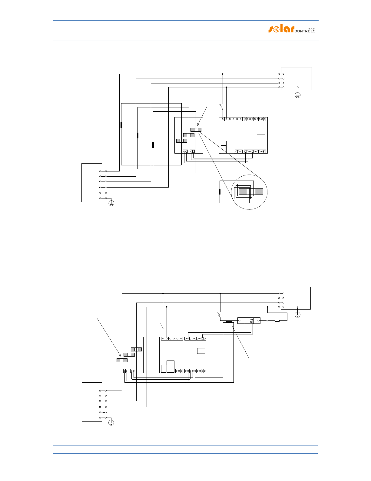
Figure 8: Connection of an external current transformer (marked as TR, this may be another current sensing module or other compatible
current transformer) to measure the current flow through the appliance. The secondary transformer circuit is connected between the Y
terminal and any ANDIx input, which must be configured correctly in WATTconfig. In this example, ANDI1 function must be set to power
measurement and the Measurement Source option must be set to SSR1. It is also possible to use an external impulse output meter and
connect this output to the ANDI input, which must then be set to the S0 pulse counter function.
Figure 9: Connection of external meter with S0 impulse output. The meter can measure, for example, the energy produced from the PV
plant. The S0 output of the meter is connected between the GND terminal and the ANDIx input, which must be further configured
correctly in WATTconfig. In this example, the ANDI1 input must be set to the S0 pulse counter function, and the Measurement Source
option must be set to one of the Lx items if the meter measures the PV power produced.
Figure 10: Connection of supported types of temperature sensors to the regulator. The DS18x20 digital sensors are connected three-wire
to the GND, DQ and +5V terminals, analog sensors are connected two-wire between the GND terminals and the corresponding ANDIx
input, which must be correctly configured in WATTconfig. In this example, ANDI3 must be set to NTC and ANDI4 to PT1000.
L1
Current sensing module
N
Regulator
IL1
IL2
IL3
B
DQ
Y
LT
ANDI3
ANDI4
ANDI2
R2_1
R2_2
L1
N
ANDI1
R1_1
R1_2
IL3
IL2
IL1
Y
House wiring
+ PV plant
PE
PE
Public grid
connection point
(main energy meter)
Wire goes through
current transformer
LT (low tariff signal)
I >
B6A
USB
LAN
micro
SD
GND
S2-
S1-
S4-
S3-
S6-
S5-
+12V
+5V
A
RS485
L2
L3
L1
N
L2
L3
Auxilliary energy meter
with S0 impulse output
L1
Current sensing module
N
Regulator
IL1
IL2
IL3
B
DQ
Y
LT
ANDI3
ANDI4
ANDI2
R2_1
R2_2
L1
N
ANDI1
R1_1
R1_2
IL3
IL2
IL1
Y
House wiring
+ PV plant
PE
PE
Public grid
connection point
(main energy meter)
LT
I >
B6A
USB
LAN
micro
SD
GND
S2-
S1-
S4-
S3-
S6-
S5-
+12V
+5V
A
RS485
L2
L3
L1
N
L2
L3
DS18x20
NTC
PT1000

WATTrouter Mx - user manual
How to fit and setup the device
Page 16 from 82
Figure 11: Example for 0-10V signal output from the regulator. The corresponding SSR outputs must be set to the PWM function, and the
desired PWM modulation frequency must be set. The outputs SSR 4 to 6 generate the desired signal directly (but the signal may have a
significant output ripple at slow PWM modulation), SSR outputs 1 to 3 generate only PWM, so you must use external PWM/0-10V
converter to get the desired signal.
Figure 12: Connection of positive SSR anodes (typically A1 +) to an external DC source + 12V when the internal power supply of the
controller is heavily loaded. SSR control circuit can be normally powered by + 12V or + 5V terminals. We recommend the + 12V (must be
used if the control voltage >5V is required). However, using the two built-in relays, the voltage at the + 12V terminal can drop to + 8V
and will not fully drive the SSR 4 to SSR 6 outputs in the PWM / 0-10V function, and some of the built-in relays does not need to be
switched on. In this case, connect all SSRs to an external power source as shown in the figure. Firmware since version 1.5 already checks
the voltage drop at + 12V terminal and also enables software optimization of the built-in relay consumption. For details, see chapter
Measured parameters and statuses and chapter Other settings tab.
L1
Current sensing module
N
Regulator
IL1
IL2
IL3
B
DQ
Y
LT
ANDI3
ANDI4
ANDI2
R2_1
R2_2
L1
N
ANDI1
R1_1
R1_2
IL3
IL2
IL1
Y
House wiring
+ PV plant
PE
PE
Public grid
connection point
(main energy meter)
LT
I >
B6A
USB
LAN
micro
SD
GND
S2-
S1-
S4-
S3-
S6-
S5-
+12V
+5V
A
RS485
L2
L3
L1
N
L2
L3
0-10V
+12V
GND
PWM+
PWM-
+
-
0-10V
(through converter)
+
-
0-10V
(direct output)
PWM function
PWM function
L1
Current sensing module
N
Regulator
IL1
IL2
IL3
B
DQ
Y
LT
ANDI3
ANDI4
ANDI2
R2_1
R2_2
L1
N
ANDI1
R1_1
R1_2
IL3
IL2
IL1
Y
Load 1
(only resistive)
House wiring
+ PV plant
PE
PE
Public grid
connection point
(main energy meter)
Wire goes through
current transformer
Relay 230VAC
LT (low tariff signal)
I > I >
Load 2
(only resistive)
M
1
Load 4
(e.g. motor*)
M
1
Load 5
(e.g. motor*)
Load 3
(only resistive)
I >
B6A
USB
LAN
micro
SD
GND
S2-
S1-
S4-
S3-
S6-
S5-
+12V
+5V
A
RS485
*) Always use separated contactor
for motors and loads with cos(φ)<>1!
L2
L3
L1
N
L2
L3
L1
T1
A1+
A2-
RGS1A60D..
L1
T1
A1+
A2-
RGS1A60D..
L1
T1
A1+
A2-
RGS1A60D..
12VDC

WATTrouter Mx - user manual
How to fit and setup the device
Page 17 from 82
The controller may be connected only to 230VAC, 50 Hz public electric grids. Regulator must be
protected with a circuit breaker - recommended rating is B6A - and connected loads must also be
adequately protected! Installation may only be done when the facility’s main circuit breaker is
turned off!
Upon completion of the installation process make sure to check thoroughly the connection of the
regulator and the current sensing module. Also check connection of all pluggable terminal blocks,
where NO power grid voltage or voltage outside of tolerances specified in the chapter Technical
specifications may be connected! NO other than resistive (heating) loads may be connected to
power SSRs! Regular relays CANNOT be connected to SSR outputs! It is prohibited to connect
loads with higher than the maximum allowed nominal power! If you fail to observe these rules it
is almost guaranteed that you will damage the regulator and lose your warranty!
For the correct operation of the controller, it is absolutely necessary to ensure proper phasing of
the measured currents with the internal voltage detector. This can be done by selecting the
appropriate phase in the Input Settings tab. It is strongly recommended to connect the controller
so that the phase conductor fed to terminal L1 corresponds to the phase conductor wired
through the measuring transformer corresponding to the IL1 input, which will allow the
measurement to match the default settings of the controller (and therefore the same as required
for older models). The IL2 and IL3 current inputs can be connected arbitrarily, the respective
phases for these inputs must be set up correctly in the WATTconfig control software.
We strongly advise you to protect your loads connected to the power SSRs with fuses suitable for
protection of semiconductors, rather than regular circuit breakers. Please note that SSRs
damaged by overcurrent or short-circuit most likely cannot be claimed under warranty. Make
sure that solid state relays are correctly connected, as required by their user manual.
No electronic devices (various measuring and protective elements, such as sub-meters and
residual current circuit breakers) may be installed between the SSRs and the appliance, since
they may be damaged by impulse power! Always install these devices on the line between the
fuse and the solid-state relay where constant power is available.
If your facility is located in an area with higher risk of overvoltage spikes due to atmospheric
discharge (lightning), we strongly recommend fitting a suitable overvoltage/lightning protection
between the distribution box with the main energy meter and the current sensing module!
If any sensors are connected to the ANDI multi-purpose inputs, it is imperative to properly
configure their function, otherwise these and/or even the ILx inputs may not work properly!
The current sensing module supplied with the WATTrouter Mx controller is fully compatible with
the current sensing module supplied with older types of WATTrouter CWx, WATTrouter CWx
SSR, WATTrouter ECO, WATTrouter M and vice versa. The current sensing module installed with
these controllers can be used with the WATTrouter Mx controller (and vice versa). However,
please note: The terminal marked GND for these older measuring modules must be connected to
the Y terminal of the Mx controller, not to the GND terminal!
If the regulator is constantly connected to PC via USB interface (mostly if long cable is used), we
strongly recommend using an USB isolator!

WATTrouter Mx - user manual
How to fit and setup the device
Page 18 from 82
Note: It is allowed to connect only pure resistive loads to power SSRs. These loads cannot be fitted with own
electronic control system nor with built-in motors (e.g. fans - see the note below). These loads may only have
regular mechanically controlled thermostats and indication LEDs or neon lamps. Almost any regularly produced
boilers, immersion heaters, infra radiators, heating floor pads, motor-free dryers (infra dryer), oil heaters,
cartridge heaters in a solar tanks, etc. may be used.
Note: Each SSR output is capable of providing power to heating loads with built-in fan for longer time (such as
hair dryer, heat radiator). These loads are fitted with a built-in thermal protection, which, if synchronous SSR
control mode is used for that load, will disconnect the load for low power of SSR output (in this scenario, the
built-in fan’s power is not sufficient to cool down the heating element of the load). Therefore, consider fitting
these loads to SSR outputs carefully.
Note: Heating loads connected via residual-current circuit breaker may be connected to SSR outputs.
Note: Heating loads with nominal power up to 2 kW may be connected to relay outputs directly, without using
external contactor.
Carefully examine connection of the controller and then turn off all circuit breakers and deactivate fuse
switches for connected loads. Then turn on the main circuit breaker and the regulator circuit breaker (L1 power
supply). The LED PWR lights up (power on indication). If the light is off, or if it does not shine permanently, or if
the LED ERR starts to flash (error status), proceed according to instructions specified in the Troubleshooting
chapter. In default status no output is active and therefore, no load will be turned on.
Now the controller is fitted and ready for configuration.

WATTrouter Mx - user manual
How to fit and setup the device
Page 19 from 82
IN SER TIN G T HE SC-GATEWAY MODUL E
The SC-Gateway module is an optional accessory that provides wireless communication with wireless endpoints. Insert the module to sockets in the regulator according to the images below. Before insertion you must
lift the regulator cover with a small screwdriver or similar tool.
Make sure the regulator is turned off before inserting the module!
Keep the proper orientation of the module. Reverse orientation can damage the module!
Insert the module gently, without unusual force!
Figure 13: Insert the module to sockets on regulator
mainboard, use vertical movement as the arrow indicates.
Figure 14: Resulting position of the module inside the regulator.
After regulator power on, the blue LED on the module must indicate the module initialization sequence, refer
to chapter LED Statuses. In case that does not happen, refer to chapter Troubleshooting.

WATTrouter Mx - user manual
How to fit and setup the device
Page 20 from 82
DEVIC E CONFIGURATION
You will need notebook or regular PC (placed closely enough to the regulator) with USB interface (hereinafter
referred to as a computer only). The controller is configured using the WATTconfig Mx control software. The
installation package for this software is available on manufacturer’s web pages. Before installing the
WATTconfig Mx control software you need to install the driver for USB interface.
In order to connect to the USB interface, it is necessary - due to safety reasons - to turn off the
entire distribution box before manipulation.
Tip: After you configure Ethernet network connection you may perform all settings including firmware update
over the Ethernet interface. You do not need to use the USB interface at all, provided that the parameters of the
connected LAN are the same as the default controller parameters (see below), and if there is no conflict
between IP addresses or conflict between physical MAC addresses.
Tip: The controller can be monitored and configured via the RS485 interface using the WATTconfig Mx software.
An appropriate USB/RS485 converter is required to connect to this interface using a PC. The RS485 interface is
reserved for various other protocols (such as MODBUS RTU) which might be implemented in future.
If you cannot continue with the settings (due to any reasons), proceed according to instructions specified in the
Troubleshooting chapter.
US B D RIV ER INS TAL LAT I ON
The installation procedure is described for Windows XP, English locale. The procedure is similar for newer
systems, or it is much simpler (Windows 7).
1. Insert the attached USB cable to the USB connector of the regulator and then to the computer.
2. Turn on the controller. The green LED PWR must light up (power on indication). Also the yellow LED
USB light will or should flash briefly (communication process indication) as the USB device will start to
register in your computer.
3. After a moment, following window must appear confirming that a new device was found:

WATTrouter Mx - user manual
How to fit and setup the device
Page 21 from 82
4. Select: No, not this time. In the following window select: Install from a list or specific location
(Advanced).
5. Select the path to the driver file:

WATTrouter Mx - user manual
How to fit and setup the device
Page 22 from 82
6. The driver has been installed successfully, if this window appears:
7. During the installation there might appear a warning about an invalid digital driver signature. Just
ignore it. The device is registered in your system device manager as USB serial converter (menu
Universal Serial Bus Controllers)
8. You must perform the same installation process for the second USB serial port device.
WATTC ONF IG MX CONTRO L SO FTWARE INSTA LLATIO N

WATTrouter Mx - user manual
How to fit and setup the device
Page 23 from 82
1. Turn on the PC.
2. Run WATTconfig_Mx_Setup.exe which you may download from manufacturer’s web pages.
3. Follow the on-screen instructions.
SE TTI NG UP MAI N F UNC T ION
1. Click on START button in your PC and run the WATTconfig Mx control software. The system will display
the main software window.
2. Make sure that the controller is turned on and connected to your computer. Make sure that USB
interface driver is correctly installed.
3. Select USB interface connection mode (field next to the "Connect" button).
4. Select correct port for connection. This can be done in the dropdown menu Port in USB/COM driver
configuration window, which will show up by clicking on button Configure connection.
Note: Unlike WATTrouter CWx or WATTrouter M devices the WATTrouter Mx uses a serial port connection
(COMx). This port is always virtual port because the controller is connected via USB. Once more ports are
displayed, it is necessary to check in Windows device manager, which port is assigned to USB Serial Port.
5. Click the "Connect" button. The controller should be now connected and the connection indicator (a
stripe) should be displayed in green. If it is not, and the system displays an error message, wait until
the USB driver is ready for use in your PC, or inspect the settings in the USB driver configuration
window. You may display the window by pressing the Configure button.
6. After establishing successful communication, you should be able to see the current measured values
(power outputs on individual phases, etc.). No outputs should be active ("unused" priority). Also no
time schedules should be used.
7. Now you can configure measuring inputs. This can be done on the "Input settings" tab. First, you set
the phase sequence and then the direction of current flows through the current sensing module.
a. Setting up phase sequence: Turn off the PV-plant and turn on a resistive load on each phase
which will be involved in the measuring process. The system will display measured active
power on each individual phase. For now, you may ignore the signs of the measured power
values. Now, in the Phase field select corresponding phase, based on the actual status
recognized by the controller, and press Write button. The configuration will be saved in the
controller. If the output values measured on individual phases differ too much from the
reality, change the phase for given input and again press the Write button. Repeat these
steps for all 3 inputs IL1, IL2 and IL3 until all measured powers are displayed correctly.
b. Setting up the direction of current flows through the current sensing module: As specified in
the previous steps, leave loads on measured phases switched on. When the PV-plant is
turned off, all measured power output values must be smaller than 0 or equal to 0. If any of
the measured power outputs is positive it means that the phase wire is passing through the
current sensing module in a reverse direction. Use the Current orientation field for the
relevant phase, select the reversed option and press the Write button. The configuration will
be saved in the controller. Now, all measured power outputs must be <= 0. Turn the PV-plant
on and turn off all loads. Now, measured outputs must be positive (>=0). If they are not, or if
the measured values do not correspond with nominal power ratings of the connected loads,
or if they do not correspond with the power output of the PV-plant, you have either still
connected another loads (which you don‘t know about, such as various loads in stand-by
mode, etc.), or the phase sequence in voltage or in current inputs does not match, or you may

WATTrouter Mx - user manual
How to fit and setup the device
Page 24 from 82
have a defect in household wiring. In any case, make sure to inspect the entire electric
wiring.
c. You can verify the correctness of measurement input configuration by using the chart "Input
checking oscilloscope". This chart shows measured current waveforms in selected phase,
values are given in units of the built-in A/D-converter (digits), these are not normalized to
amps due to performance. This feature should only aid the fitter when configuring the
measuring inputs. Always verify with a resistive (heat) load only, so that the phase shift
between voltage and current is zero ( )! Moreover, in order to verify the
measuring inputs the amplitude of current half-wave should always be greater than 1000
digits (to be sure about the correctness of the settings).
Note: During normal operation there may be shown even "exotic" waveforms. Be sure this is
the real current flowing through the phase wire, a superposition of currents flowing through
the connected appliances which are not always sinusoidal or their power factor varies from
one.
Figure15: Input is fitted correctly - sine wave of the current flowing through a resistive (heat) load is in phase with the voltage.
WATTconfig shows negative values on selected phase (consumption). Left image appears when there is normal (default) current flow
direction, right image appears for opposite direction. Note: The PV-inverter throughput appears exactly as the opposite, because the
current is anti-phased with the voltage. If the inverter performs power factor compensation you can observe corresponding phase
shifts.
Figure 16: Input is fitted incorrectly - sine wave of the current flowing through a resistive (heat) load is not in phase with the voltage and
either precedes (image left) or lags behind (image right) the voltage by 1/3 of mains half-wave. Measuring inputs are fitted incorrectly
and you need to select correct option in the Phase field for respective input.
8. After a successful setup of measuring inputs you may begin to test outputs. This can be done on the
"Output settings" tab. Each connected load must be tested separately. Turn on circuit breaker or
activate fuse switch for the first output, and press the TEST button for the corresponding output. The
load should switch on. When the load is switched on, the active power drawn by connected load must
be detected by the current sensing module on the relevant phase.

WATTrouter Mx - user manual
How to fit and setup the device
Page 25 from 82
9. After you have successfully tested all outputs, you may begin to configure the control mode in the
Control settings field. This can be done on the "Other settings" tab. Set this mode either to "sum of all
phases" or to "each phase independently", based on the configuration of your 4-quadrant energy
meter. If you are not sure how your energy meter is configured, please contact your electricity
provider or use the "each phase independently"-mode, which works for any configuration of the
energy meter.
In order to use the "each phase independently"-mode, it is necessary to select correct phase for each
output, i.e. phase where the corresponding load is really connected. Controller will then try to
maintain zero energy flow in each phase ("phase zero"). You may check correct phase assignment
again through the TEST button. Within a short time after pressing the button the active power drawn
by connected load must be detected by the current sensing module on relevant phase.
As far as your energy meter is configured to evaluate sum of powers in all phases, you may use the
mode "sum of all phases". Here the controller will try to maintain virtual zero energy flow. This means
that for output switching it takes the sum of measured powers from all 3 phases ("virtual zero"). Here
you may try experimenting with both methods, but it is recommended to use "sum of all phases"mode, because it is more effective for the user.
10. After a correct setup of the control mode, you may start to assign priorities and power ratings for
individual outputs. This can be done on the "Output settings" tab. Select priorities of individual loads.
The switching process based on priorities may be described as follows:
By default (during night), all loads are turned off. If PV-plant production (available surplus energy) is
determined in the morning, the output with the first (highest) priority is switched on. The switching
time is different for proportional outputs (their function equals to proportional or PWM) and relay
outputs. Proportional outputs are switched on almost immediately (this is the proportional switching),
but relay outputs are switched on only if the available surplus energy exceeds the value specified in
the Connected power field (there is also a different solution available – see the "Prepend before SSR"
function). When the load is switched on (for proportional output it means the load is switched to the
value specified in the Maximum power field), the system waits until the power output of PV-plant
increases again (sunrise). If additional available surplus energy is determined when the load with first
priority is switched on, then load with second priority is switched on in the same mode. The same
applies to all outputs. If the available surplus energy decreases, or if another load in the household is
switched on, active outputs are disconnected according to preset priorities but in reverse order (first,
the load with the lowest priority gets disconnected).
The value in the "Connected power" field should be equal to the power rating of the connected load.
For relay output it must be higher or equal to the power rating of the load, otherwise the controller
will not operate correctly, and the load will be repeatedly turned on and off. For proportional output
this value only configures the control dynamics, but it should be also equal to the actual power rating
of the load.
The fields On-delay time and Off-delay time for relay outputs specify the time delay to switch the relay
on or off after a condition has been detected to do so. This feature is necessary for loads which cannot
be switched on frequently.
Set outputs according to the connected loads and based on your priorities and then press the Write
button. The configuration will be saved in the controller. Now the main function of the controller
should be configured.
11. Test the main function of the controller, or possibly, modify priorities for outputs and power settings
of connected loads.

WATTrouter Mx - user manual
How to fit and setup the device
Page 26 from 82
SE TTI NG UP COM BIW ATT MOD E
After you have successfully tested the main function, you may start to configure CombiWATT mode, provided a
low tariff signal is connected to the controller (it may be used even if single tariff rate is present – see notes
below). This can be done on the "Output settings" tab. CombiWATT mode provides constant daily energy
supply to the connected loads. This mode is indispensable if you need to heat up water but also e. g. if you use
a swimming pool filtering system during cloudy days or when your PV-plant is temporarily out of order. In
CombiWATT mode, energy is taken both from PV-plant and from public grid.
Determine the optimal value of energy in kWh for the connected load (for example for a boiler or immersion
heater), which you plan to supply the load with every day. For example, for a boiler it is suitable to determine
the value of electric energy based on the average consumption of hot water. Usually, electric energy necessary
to increase the temperature of hot water by 40°C equals to:
3600000
][*][*
][
KTlVc
kWhE
V
. If you enter it
into the formula you will get:
][*0464.0][ lVkWhE
. For a 180 liter boiler it will be 8.36 kWh. We
recommend to increase this value by the daily heat loss of the boiler and also to modify (reduce) the value
based on the actual average consumption of hot water.
Note: If you are heating water for example, the controller does not "know" how hot the water in the boiler is
and therefore, the assumed values of the supplied electric energy may be higher than the actual delivered
energy (the boiler thermostat may shut it off at any time). If you want to count only real supplied energy to the
boiler then connect additional measurement for it according to Figure 8.
Mark the CombiWATT field for the relevant output (output must be activated, which means that the output
must be assigned with the relevant priority), enter the established value of the daily electric energy in kWh and
press the Write button. The configuration will be saved in the controller.
The CombiWATT mode is activated only if ALL the following conditions are met:
a. The output is activated (priority has been assigned to the output - that means the output is
not in the "not used" status).
b. PV-plant does not produce electric power (active powers at all measured phases are <= (less
or equal to the) CombiWATT production limit field).
c. During the day, PV-plant did not supply the load with the required amount of energy, that is,
the field "Supplied energy" is lower than the value specified in the "CombiWATT [kWh]" field
for the relevant output.
d. Low tariff signal has been detected (the info LED "low tariff" is red). Energy from public grid is
always consumed in CombiWATT only if low tariff is present. See note below to learn how to
configure this mode if you don't have double tariff rate.
e. The "Time to activate CombiWATT"-field shows zero.
The CombiWATT mode is deactivated if some of the following conditions will apply:
a. The value in the field "Supplied energy" reached the "CombiWATT [kWh]" value for the
relevant output.
b. PV production has been detected at some of the measured phases (active power at some
measured phase is > (greater than the) CombiWATT production limit field).
c. The low tariff signal is turned off.
Reset of energy counters (that is reset of values in the fields "Supplied energy")

WATTrouter Mx - user manual
How to fit and setup the device
Page 27 from 82
a. At sunrise. Counters are reset to zero at sunrise time, which is automatically calculated by the
controller.
b. At fixed time. Counters are reset to zero at a preset time.
More information about counter reset processing is available in the chapter Description of
WATTconfig Mx items.
Note: For boilers/immersion heaters or any other hot water tanks the CombiWATT mode "does not care"
during what time of the day the water is heated and used. The CombiWATT function only supplies the
preset minimum daily power to the boiler and thus making sure that there is enough hot water when the
recommended configuration is used. In cases when even under the recommended configuration hot water
is not available in required amount, we recommend to gradually increase the daily energy limit
("CombiWATT [kWh]") for example, by 1 kWh, in order to make sure that hot water is available and at the
same time that not too much energy is consumed from public grid. This is recommended mostly for
households where consumption of hot water is high at the evening. Here it may come to the situation
where water is sufficiently heated during the present day by the PV-plant, but the next day the plant is not
capable of providing the necessary amount of energy (cloudy weather). The CombiWATT mode may also be
aided by enforcing the relevant output with a time schedule. Based on user preferences, time schedules
may even completely replace the CombiWATT mode. For more information see chapter Setting up time
schedules.
If you do not have low tariff signal available (either you don't have double tariff rate or the signal cannot be
utilized) but you still want to use the CombiWATT mode, connect the GND terminal to the LT terminal. In such
scenario, the low tariff signal will be active at all times and the CombiWATT mode will be activated after
production of PV-plant comes to an end (after sundown).
SE TTI NG UP TIM E S CHE D ULE S
Up to 4 independent time intervals may be set for each individual output. During these time intervals the
relevant output may be forced to be switched on, or the switching process may be prohibited (restricted). The
enforcing/restricting process may be further conditioned by the presence of the low tariff signal and / or by the
status of daily energy counters for the relevant output (field "Supplied energy") or temperature conditions.
The actual configuration of time schedules is done on the "Time schedules" tab. For more set up information,
see the chapter Description of WATTconfig Mx items, Time schedules tab.
AN DI INP UT CON FIG URA TION
The controller has 4 multi-purpose ANDI inputs to connect:
1. WATTrouter-compatible external current transformers (e.g. another current sensing module or other
compatible current measuring transformers). These can measure powers exactly as ILx inputs;
2. External meters with impulse output S0, which meets the parameters specified in the technical
specification and its output signal provides information about the measured electrical energy;
3. Analog temperature sensors of NTC type;
4. Analog temperature sensors type PT1000.
ANDI inputs are not required to be used. They play an auxiliary role and provide additional information to the
controller. For more information, see chapter Description of WATTconfig Mx items, Input settings tab.
WIREL ESS CO MUN ICA TIO N SETTINGS
Note: This function is accessible, once SC-Gateway module is inserted.

WATTrouter Mx - user manual
How to fit and setup the device
Page 28 from 82
WATTrouter Mx optionally integrates up to 6 wirelessly controlled devices which can be purchased as
accessories. Wireless connection solution can be applied in buildings, where installation of wire connections
between controller and devices would be too difficult.
Attention: Before ordering of this accessory function, assure that wireless devices will be accessible by the
controller. The accessible distance is based on construction of the building and it is possible to extend this range
by the repeaters. Further information can be obtained from technical support.
This function requires SC-Gateway module which needs to be inserted into regulator. To install this SC-Gateway
module, refer to the SC-Gateway user manual. It is also necessary to buy at least one wireless peripheral
(wireless socket or wireless module to be installed on the DIN rail).
How to activate wireless peripherals:
1. Connect wireless peripheral to electrical network and wait till the device gets registered in wireless
network. SC-Gateway module acts as a coordinator of this wireless network and the controller is being
informed once new device is detected. In such case, WATTconfig software will show the Add wireless
station window. If this dialog does not appear even after longer period (1 minute or longer), the
peripheral is probably out of connection range of regulator – proceed according to chapter
Troubleshooting.
2. In window "Add wireless station", set the name tag of the station and choose the table line where the
new peripheral should be registered.
3. Upon closing the Add wireless station dialog (see Fig. "Other Settings" tab) press the Write button. The
configuration will be saved in the controller.
4. On the "Output settings" tab, assign to the logic output WLS the configured wireless peripheral by
using the Station and Device fields. Press the Write button. The configuration will be saved in the
controller.
5. Test with Test button, respective output on the peripheral should respond. If it does not, proceed
according to Chapter Troubleshooting.
6. In case of usage of more wireless peripherals, repeat this procedure from point one for each one. Do
not connect new stations to power line at the same moment, because otherwise the identification of
new station will be impossible.
FI NIS HIN G T HE CON FIG U RAT ION
After setting up the controller according to previous chapters the controller is fully configured. You may save
the preset configuration by pressing the Save button or you may load it at any time by pressing the Open
button. This way you may create several different configurations and monitor them for some time and
determine which one provides better utilization of energy self-consumption in your facility or household.
After you have completed the settings using the USB port then in case of manipulating within the distribution
box turn off entire distribution box, remove the USB cable and turn on the distribution box again.
Tip: In order to maintain continuous monitoring the controller can be kept connected either via USB or Ethernet.
If you want to use permanent USB connection, then it is recommended using a suitable USB isolator or USB
connection extender via Ethernet (for example Silex 3000GB). To use permanent Ethernet connection you may
connect the network cable directly to your network router or switch.
WATTrouter Mx - user manual
How to fit and setup the device
Page 29 from 82
DESCR IPTION OF WA TTC O NFI G M X I TEM S
This chapter contains a list of all items available in the WATTconfig control software and explains their
meaning. Or you may use the controller web interface, where the items have identical names and meanings.
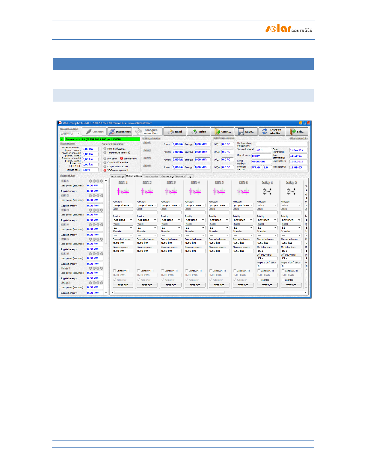
MAIN WIN DOW
The main window displays all basic measured values and statuses. Controller can be configured using
configuration tabs.
Figure 17: Main window of WATTconfig software.

WATTrouter Mx - user manual
How to fit and setup the device
Page 30 from 82
MEASU RED PARAMETERS AND ST ATU S ES
Measured values:
Power on ph. Lx - the actual value of the active power measured on the relevant phase wire. Positive
value means production (PV-plant supplies power to the grid); negative value means that power is
being drawn from the grid.
Power sum L1+L2+L3 – sum of active power outputs in all three phases.
Voltage at L1 – voltage on phase L1 which powers up the regulator. This voltage value is used to more
accurately calculate the power output than for the older WATTrouter models where the voltage was
not measured and a constant value of 230V was assumed. It is also used for calculating the powers on
other phases where a similar voltage value is assumed.
Error and info status (gray in inactive status, red in active status):
Missing voltage L1 – failure of the synchronization circuit that detects the voltage at L1 terminal. This
is a hardware failure of the regulator and it must be replaced or repaired.
Wrong voltage value L1 - grid voltage is too low (<200VAC) or high (> 260VAC). Firmware since version
1.5 signals this fault separately from the previous general state "Missing voltage L1". The controller
will remain functional in this malfunction state, only indicating the problem. Instead of the measured
voltage value, a fixed voltage of 230VAC is assumed (as for previous models CWx, M, ECO). If the
voltage at terminal L1 is within the specified limits, it is a circuit failure that measures the voltage, and
replacement or repair of the controller is recommended.
Temperature sensor(s) – somewhere in time schedules temperature conditions are defined according
to a temperature sensor (ANDI or DQ input) but this sensor does not work. Change the time schedule
configuration or fix the problem with the sensor.
DC source overload - Voltage level at terminal + 12V drops below + 9V relative to GND. This
malfunction can occur when the internal DC voltage source is heavily loaded. The firmware since
version 1.5 checks this and eventually signals this failure. This malfunction lasts for the duration of the
cause and for a further 60s afterwards. Typically, this failure occurs when all 8 internal outputs are
used or there is overload on the + 12V or + 5V terminals may (there can be for example a malfunction
of some digital sensor if powered from + 5V terminal). Please check that the + 12V or + 5V terminals
are not overloaded. When the two internal relays are occupied, connect the control circuits of all used
SSRs to an external source (see Figure 12). You can also enable the Optimize internal relay
consumption feature (see chapter Other settings tab) which might help to reduce the power
consumption of internal relays.
Low tariff – if the low tariff signal is detected the red light comes on, otherwise it is grayed.
Summer time - informs the user that the summer time mode is active. Summer time starts at 2:00 CET,
on the last Sunday in March and ends at 3:00 CEST, on the last Sunday in October. If the option "Use
summer time" is not marked on the "Other settings" tab, the indicator remains inactive.
CombiWATT is active – informs the user that CombiWATT mode is active. This indicator is active if the
condition necessary to run CombiWATT is valid, if the low tariff is active and if the CombiWATT
function has been configured for some output.
Output test is active – informs the user about a status when some of the outputs have been activated
by the TEST button. Output tests done via LAN interface are protected from unauthorized access or
intervention.

WATTrouter Mx - user manual
How to fit and setup the device
Page 31 from 82
SC-Gateway present – informs the user about the presence of the SC-Gateway module in the
regulator.
Output statuses:
Load power - the power drawn by the load connected to the relevant output. It is either:
a. Estimated power based on the output settings and may not correspond with the actual
power output of the load, or:
b. Measured power using an external current transformer connected to the corresponding ANDI
input. If the output is switched on by the controller, but the assigned ANDI input does not
measure any output (for example, the appliance is disconnected by its internal thermostat),
the item flashes.
Supplied energy - daily energy counters counting power already supplied to the relevant output. It is
either:
a. Estimated energy supplied to the load, which is based on the output settings and may not
correspond with the actual amount of the power supplied to the load, or:
b. Measured energy using an external current transformer connected to the corresponding
ANDI input.
These energy counters inform CombiWATT mode or the corresponding time schedule about the
energy already delivered to the load and at the same time, they also inform the user about the
amount of delivered energy. Counters are reset to zero based on the configuration of "CombiWATT Energy counter reset"-field in the Other settings tab.
Note: In case ad a) the WATTrouter device does not "know" the status of the load and therefore,
counters may also show much higher energy values than those actually delivered to the load (for
example, if the boiler is heated up during the day and turned off by the thermostat).
Status output indicators - inform the user about the reason for switching, or possibly about the reason
for output restriction. There are 4 indicators:
a) Blue - it is displayed only if the output is switched on due to basic control process according
to the available surplus energy from PV-plant. This indicator also signals possible off-delay
time for the relay output (after being enforced by time schedule or CombiWATT mode).
b) Violet - it is displayed only if the output is switched on by the CombiWATT mode.
c) Green - it is displayed only if switching is enforced by time schedule.
d) Red - it is displayed if the output is restricted by time schedule.
ANDI input status:
Power- displays electric power which is measured either with an:
a. External current transformer when the ANDI function is set to power measurement or with
an:
b. External meter with S0 impulse input when the ANDI function is set to S0 pulse counter. The
value is calculated using the following formula:
kWhp
[s].Impt
3600
= P[kW]
Where:
P – final power (this field)

WATTrouter Mx - user manual
How to fit and setup the device
Page 32 from 82
tp – period of impulses
Imp
kWh
– number of impulses per kWh (see FB input settings)
The measurement dynamics depends on the impulse frequency. It may be very small for small
measured powers. The maximum measurable period of impulses is set to 15 seconds (at 1000
impulses per kWh it corresponds to an output of 0.24 kW). If the measured power is lower,
zero is displayed.
Energy – displays electric energy counted either with an:
a. External current transformer when the ANDI function is set to power measurement or with
an:
b. External meter with S0 impulse input when the ANDI function is set to S0 pulse counter. The
value is calculated using the following formula:
kWh
p
Imp
Imp
[kWh]E = E[kWh]
Where:
E – final energy (this field)
Ep – initial energy at the input (see FB input settings)
Imp – number of impulses registered by FB input since the moment the impulses were
connected to this FB input. These counter values are not displayed.
Imp
kWh
– number of impulses per kWh (see FB input settings)
Impulses are counted only if the controller is operating. It is only an auxiliary and informative
feature of the controller. Counted impulses are saved in the internal EEPROM memory every
hour. In case of a short time power supply failure these values should not be very different
from the actual reality. More frequent impulse saving is not possible due to technical reasons.
If these values do not correspond with the value shown on the display of the connected
energy meter, modify the field "Energy offset" to match the value of the energy meter, check
the "Reset energy"-field and press the Write button.
Temperature – displays the temperature measured by the corresponding ANDI input when the ANDI
function is set to NTC or PT1000.
Digital temp. sensors:
Temperature – displays the temperature measured by the corresponding sensor.
Other statuses:
Configuration/object name - it is used to set label to the facility or the current configuration. Text may
contain maximum of 16 characters in ASCII encoding.
Sunrise today – it displays time of sunrise for today. This time is calculated directly in the controller
based on the actual calendar date and the actual geographic location of the facility/building (see
"Geographic location" on the "Other settings" tab). The calculated time is converted to the current
local time based on configuration of the "Use summer time" and "Time zone" settings. The official
sunrise zenith, 90° 50' is used. Sunrise time is used to reset energy counters ("Supplied energy"-fields)
in the main window, provided that the applicable mode in the field "CombiWATT – Energy counter
reset" is selected.
Day of week – shows the current day of week, which is obtained from the controller date.

WATTrouter Mx - user manual
How to fit and setup the device
Page 33 from 82
Serial number- displays serial number and it is unique for each regulator.
Firmware version – displays actual regulator firmware version.
Date (regulator) – it indicates the real time running inside the regulator (date part).
Time (regulator) – it indicates the real time running inside the regulator (time part).
Note: Regulator real time is backed up with a built-in lithium battery, so it runs even if the regulator power
supply is turned off.
Date (client) – it displays the real-time running on the PC (date part).
Time (client) – it displays the real-time running on the PC (time part).
IN PUT SE TTI NGS TA B
In this tab you may set measuring inputs, multi-purpose ANDI inputs and configure digital temperature
sensors.
Note: The ANDI multi-purpose inputs are an extension of FB input functionality from older WATTrouter models
that only worked as S0 pulse counter.
Common settings for Measurement input settings and ANDI input settings:
Label – used to assign a label for the relevant input. Label may contain a maximum of 16 characters
in ASCII encoding. For ILx inputs it cannot be modified.
Function – is used to select proper function for the input. For ILx inputs it cannot be modified. The
ANDI inputs may perform following functions:
a. Power measurement – default function. Connect WATTrouter-compatible external current
transformers (e.g. another current sensing module or other compatible current measuring
transformers). Do not overload the ANDI inputs with bigger primary currents than 15A (which
corresponds to secondary current 15mA);
b. S0 pulse counter – connect impulse output S0 of an external meter, which meets the parameters
specified in the technical specification and its output signal provides information about the
measured electrical energy;
c. NTC – connect analog temperature sensors of NTC type;
d. PT1000 - connect analog temperature sensors type PT1000.
Current orientation - it is used to change the sign of measured powers, if the current sensing module is
fitted in reverse position, or in cases for example, when it is desirable to pass the wire through the
module in reverse direction.
Phase - it is used to set the physical phase to given input when its function is set to power
measurement. Assign the phase so that the measured currents are in phase with voltage. Check the
assignment using a control oscilloscope and a purely resistive (thermal) load on the given phase.
Note: The Phase parameter replaces the "Phase Order Setting" menu from older WATTrouter models and
allows you to set any phasing for all inputs with the power measurement function.
Ratio for external CTs - set this ratio only if you use additional external current transformers (CTs),
whose secondary coils are shorted with a wire passing through measuring coils of the current sensing
module, as specified on figure 7. If you use standard connection for WATTrouter device that is, the
facility or household supply wire is passing directly through measuring coils as specified on figure 3,
then this ratio should be 1:1 (however, this ratio can also be used to calibrate current measurement

WATTrouter Mx - user manual
How to fit and setup the device
Page 34 from 82
even in the case of standard wiring without external measuring transformers). External current
transformers can extend the measuring range of the controller up to any value, depending on the
conversion rate of the external current transformer.
Example: Let us say you want to use WATTrouter Mx in a facility where the main circuit breaker is
rated up to 3x400A. In this case you have to buy external current transformers with ratio 400A:5A.
Connect/short-cut their secondary terminals using a wire, and at the same time, pass it through
measuring coils of the current sensing module (see Figure 7). Now set the conversion rate to 400:5.
However, in order to use the full range of the built-in A/D converter, it is recommended to make 4
turns around the measuring coils to get optimum conversion rate of 400A:20A. Then, set the
conversion rate to 400:20.
Caution: Use only external CTs for large facilities and large PV-plant power outputs. If you are using a
high conversion rate of external CTs, you have to take into account that (relatively) small power
outputs (in the example describing the optimized conversion rate 400A:20A, the limit represents
approximately 100 W per phase) are below the resolution capacity of the measuring inputs and
therefore, these power values will not be measured and equal to zero.
ANDI input settings:
Measurement source – use this to setup the energy measurement source for the ANDI input.
Following options are available:
a. Unknown – input counts e.g. energy flowing to a load or another appliance.
b. Prod. L1 – input counts energy measured on L1, value will be added to daily production stats
on L1.
c. Prod. L2 – input counts energy measured on L2, value will be added to daily production stats
on L2.
d. Prod. L3 – input counts energy measured on L3, value will be added to daily production stats
on L3.
e. Prod. L1+L2 – input counts energy measured on L1+L2, value will be equally divided to daily
production stats on L1 and L2.
f. Prod. L2+L3 – input counts energy measured on L2+L3, value will be equally divided to daily
production stats on L2 and L3.
g. Prod. L1+L3 – input counts energy measured on L1+L3, value will be equally divided to daily
production stats on L1 and L3.
h. Prod. L1+L2+L3 – input counts energy measured on all phases , value will be equally divided
to daily production stats on L1, L2 and L3 (i.e. counted value will be divided by 3).
i. SSR1 to Relay1 – input measures the power of the appliance connected to respective output.
j. WLS1 to WLS6 – input measures the power of the appliance connected to respective wireless
station. The option is displayed only if the SC-Gateway module is inserted into the regulator.
The measuring element (external current transformer or external impulse output meter)
must be physically connected to the ANDI input and therefore this measurement cannot be
easily done wirelessly.
Note: If you measure PV production on several phases with an external three-phase electricity meter, whose S0
output is connected to one ANDI input, and the inverter does not always distribute the production evenly to all
phases, you must neglect the differences. If you want to be precise, you have to use 3 ANDI inputs and 3

WATTrouter Mx - user manual
How to fit and setup the device
Page 35 from 82
external single-phase meters, or 3 external current transformers. Another current sensing module can also be
used to measure the PV production itself in this case.
Energy offset - this field can be used to set initial values of measured energies. If the values of
measured energies do not match the display on the connected energy meter (for example), put the
value of the energy shown on the display into this column and reset impulse counters to zero by
marking the option "Reset energy".
Reset energy - used to reset energy counters to zero.
Number of impulses per one kWh – this column is used to set the number of impulses per one kWh,
when the ANDI input function is set to S0 pulse counter. Set the value according to the label or manual
of the connected energy meter, inverter or according to another compatible measuring instrument. It
is recommended to use highest possible amount of impulses per kWh to get better resolution for the
power fields in the “ANDI input status” group.
Input checking oscilloscope:
This graph is primarily used to check the correctness of ILx metering inputs settings and/or ANDI inputs settings
when their function is set to power measurement. However, it can also be used to check ANDI input
configuration for other selected functions. From the drop-down menu, select the input you want to check and
follow the chart.
The oscilloscope will always display the events at the analog inputs of the WATTrouter microprocessor, which
will vary according to the assigned input function:
a. Power measurement - one whole period of measured current is displayed, the value for zero
measured power should be around 2000 digits. For more information about this view, see chapter
Setting up main function.
b. S0 pulse counter - logic 1 (about 4000 digits) will be displayed for pulse delay or logic 0 (about 10
digits) for the active pulse from the meter.
c. NTC, PT1000 - the analog value measured by the sensor or amplified by the built-in programmable
amplifier is displayed, which is further processed by the microprocessor for the temperature readout.
In case of connection of external current transformers, S0 pulse outputs or temperature sensors
to the ANDI multipurpose inputs, it is imperative to correctly configure their function or
otherwise even the ILx inputs may not work properly! You will see this as wrong diagram in the
input checking oscilloscope.
Digital temperature sensors:
Sensor type – select the type of connected digital sensors. All sensors must be of the same type.
Search for digital temperature sensors - starts searching for digital sensors connected to the DQ bus. If
all connected sensors do not appear after performing this function, make sure that the data bus
connection is correctly wired and that the shielding is also connected and working. Frequent errors in
communicating with sensors occur especially at longer distances and incorrect shielding. The feature is
password protected against unauthorized access.
Labels – used to assign a label for the relevant input. Label may contain a maximum of 16 characters
in ASCII encoding.
OUTPUT SETTING S T AB
On this tab you may set basic parameters for outputs and setup the CombiWATT mode for outputs.

WATTrouter Mx - user manual
How to fit and setup the device
Page 36 from 82
Station – specifies the wireless station – terminal device. Available only for WLS outputs that can be
activated after inserting the SC-Gateway to the regulator
Device index – specifies the output on the wireless station - terminal device. Available only for WLS
outputs that can be activated after inserting the SC-Gateway to the regulator.
Function - used to set the functionality of the corresponding output:
a. Relay- the output will operate in On/Off mode (as a relay).
b. Proportional - (only for SSR outputs or supported WLS outputs) the output will operate in
proportional regulation mode, by modulating connected load's power according to the available
surplus energy.
This mode is only for controlling the output of resistive (thermal) appliances and requires the
connection of external power semiconductor relays (SSRs)! This mode can further increase the
flicker (fast changes in mains voltage or fast flashing of light bulbs and fluorescent lamps). Before
connecting the appliance to this mode, read the flicker recommendations in the Frequently Asked
Questions section of the manufacturer's website.
c. PWM – (only for SSR outputs or supported WLS outputs) the output will operate in proportional
regulation mode, by modulating connected load's power according to the available surplus
energy, but the output signal will be PWM, see technical specification for PWM parameters.
Caution: The purpose of this mode is only to control the instantaneous power of external devices
which allow this and have corresponding input (such as some battery chargers and heating
pumps). This mode cannot be used if external solid state relays (SSRs) are connected to the SSR
outputs!
Label – used to assign a label for the relevant output. Label may contain a maximum of 16 characters
in ASCII encoding.
Priority – it is used to set priority for the relevant output. First priority is the highest; the eighth
priority is the lowest (in case of SC-Gateway presence it is possible to configure up to 14 priorities).
"Not used" means that the output is not activated. Output with higher priority will switch on "sooner"
and will switch off "later" (see the chapter Setting up main function). If you are using the "Sum of all
phases" control mode, you cannot select the same priority for two or more outputs (except for the
"not used" status). In the "Each phase independently" control mode this settings must be applied to
each phase. From the first (the highest) priority all the way down to the lowest priority. No gaps are
allowed in the priority settings, that is, you cannot set only the 1st priority and the 3rd priority,
without setting the 2nd priority as well. WATTconfig inspects priority and phase settings before
writing them into the controller.
Phase – if using the "Each phase independently" control mode you have to set the phase wire for each
output where the relevant load is connected to. The setting must correspond with the reality. Use the
TEST button to verify that.
Note: The output phases may not correspond to the physical phase settings for the ILx inputs or ANDI
inputs. The reason is that for the inputs physical phase is assigned according to the actual connection
of the measuring module and for the outputs logical phase in relation to the inputs ILx.
3f mode – if using the "Each phase independently" control mode you can set special method of surplus
energy calculation to switch on or off this output. These special methods can be used only for
symmetrical three-phase loads (such as 3-phase heating elements, 3-phase heat pumps and others),
which have to be connected on 3-phase line. Connect those loads only via external 3-phase contactor

WATTrouter Mx - user manual
How to fit and setup the device
Page 37 from 82
or 3-phase power SSR or, if you have 3-phase inverter heat pump, use corresponding control module
which can directly control the power of this heat pump.
Put one third of nominal input power of the load to the Connected Power field and set phase and
priority according to your preferences (the Phase field only serves here as reference parameter to
include this output into correct priority chain). Following special methods of energy surplus calculation
are available:
a. Min (L1, L2, L3) – output will be switched on behalf on a minimum surplus energy from all 3
phases
b. Prům (L1, L2, L3) – output will be switched on behalf on average surplus energy from all 3
phases
c. Max (L1, L2, L3 – output will be switched on behalf on a maximum surplus energy from all 3
phases
Within the assignment of one phase there can be combined single-phase and three-phase loads at
different outputs. Use this function with extreme caution and only if it is not actually possible to split
given three-phase load to 3 single-phase loads (e.g. as the mentioned 3-phase heating element).
Connected power - it specifies the active power rating of connected load. If power rating is specified in
VA and the power factor cos (Φ) is specified, you may determine the active power rating using
).S[VA].cos( = P[W]
formula. The connected power value should be equal to the power rating
of connected load for proportional or PWM function, and must be higher or equal for relay function.
Maximum power – this value applies only for proportional outputs. It determines the maximum
allowed power applicable for the connected load. In many cases this value is equal to the connected
power value, but for example, due to limited SSR cooling possibility or due to saving the surplus
energy for additional outputs, you may decrease this value. The value in the "Load power"-field may
be slightly lower than the selected maximum power value, even if the output is fully excited and
maximum power is reached (if this power is assumed and not measured by an ANDI input). The reason
is that outputs with proportional function do not switch on fully proportionally but only "quasiproportionally", which means, only in certain switching levels.
Always keep the value equal to the Connected power value in cases where the output is set to
the proportional function, causing an increased flicker (fast changes in mains voltage or rapid
flashing of light bulbs and fluorescent lamps). The output will always be permanently switched
on when fully excited. See the flicker recommendation in the Frequently Asked Questions
section of the manufacturer's website.
Prepend before SSR – allows prepending the relay output before specified number of proportional
outputs. Fill in 1 if you want a relay with lower priority to switch on when load power on nearest
higher priority proportional output reaches the relay's Connected power value. Fill in 2 if you want this
relay to be switched on when sum of load powers on nearest 2 higher priority proportional outputs
reaches the relay's Connected power value. The function works similar for higher values. This function
will violate the preset order of priorities. However, it allows using almost all available surplus energy
even if heating elements are connected to relay outputs. For example, if you are using a three-phase
heating element.
Example 1: heating element 3x2 kW connected and configured in the following way:
- 1st heating coil connected to SSR No. 1, 1st priority, connected power 2 kW, maximum power 2 kW
- 2nd heating coil connected to relay No. 1, 2nd priority, connected power 2 kW, prepend value = 1

WATTrouter Mx - user manual
How to fit and setup the device
Page 38 from 82
- 3rd heating coil connected to relay No. 2, 3rd priority, connected power 2 kW, prepend value = 1
If the SSR No. 1 is fully switched and consumes 2 kW of surplus energy and the amount of surplus
energy further increases, then the relay No. 1 will switch on and SSR No. 1 will automatically reduce its
power. If the surplus energy increases by additional 2 kW so that the SSR No. 1 is fully switched again,
then the relay No. 2 will be switched and SSR No. 1 will again automatically reduce the power output.
If the power output continues increasing, additional outputs with lower priorities will be connected.
Similarly, outputs will disconnect when the PV-plant power generation will decrease.
Note: To make sure that the function works correctly, all 3 heating coils must be active (heated) at the
same time or inactive (disconnected by the thermostat). The algorithm will not work correctly if
heating coil No. 1 is disconnected by the thermostat and the other two heating coils will continue
producing heat. In this scenario, the relay will be continuously connected and disconnected because the
controller is trying to keep "virtual zero" or "phase zero", depending on control mode, and is not able to
determine from phase wire measurements that heating coil No. 1 is disconnected. However, if we
arrange that the real output power of the 1st heating coil connected to SSR No. 1 will be measured
with some ANDI input, then the function will work properly even if the heating coils have independent
thermostats.
Note: In order to ensure correct function of the algorithm it is necessary that the SSR output - to which
the heating coil No. 1 is connected, is assigned with the higher priority than the relay No.1 with the 2nd
heating coil. If the coil No. 1 connected to a SSR output has lower power rating than the other two
remaining heating coils, then the relays will connect only after the overall power (power drawn by the
first coil + surplus energy) exceeds the value of "Connected power" field set for relay No. 1. In this case,
the part of surplus energy will be still delivered to public grid as in the case of the default function of
WATTrouter controller, without prepend mode.
Example 2: A boiler and 2 other heating elements:
- the boiler connected to SSR No. 1, 1st priority, connected power 2 kW, maximum power 2 kW,
- 1st heating coil connected to SSR No. 2, 2nd priority, connected power 2 kW, maximum power 2 kW,
- 2nd heating coil connected to relay No. 1, 3rd priority, connected power 2 kW,
a) Prepend value set to 0: In this case the 2nd coil will never be prepended and after 4kW
surplus is reached and consumed by boiler and 1st coil the controller will wait until the
available surplus is 6kW. Then it connects 2nd coil. In the meantime surplus flows to public
grid.
b) Prepend value set to 1: In order to prioritize the 2nd coil, we will take into account only the
load power of the 1st coil, which means that the boiler will always have first priority. So after
PV-surplus reaches 4 kW the 2nd coil will be connected (prepended) before the 1st coil.
c) Prepend value set to 2 and higher: In order to prioritize the 2nd coil, we will take into
account the sum of load powers of the boiler and 1st coil. So after surplus reaches 2 kW the
2nd coil will be connected (prepended) before boiler and 1st coil.
Note: The Prepend function does not affect relay output priorities. For example, if the relay 2 is set to
the nearest lower priority than the relay 1 but has a higher Prepend value than the relay 1, the relay 2
will not be prepended before the relay 1. Therefore, in this case, higher Prepend value for relay 2 than
for relay 1 is not meaningful, so don’t set it.
Minimum power – for proportional outputs when PWM function is used this value gives the minimum
power for the connected load. The output will not be activated unless available surplus energy
exceeds this threshold. Nonzero value can be useful e.g. for proportional control of inverter air
conditioner or heating pump. These devices usually don’t run with less than 1/3 of nominal power. For

WATTrouter Mx - user manual
How to fit and setup the device
Page 39 from 82
more information about controlling air conditioners or heating pumps proportionally see
manufacturer’s web site.
PWM-I – for SSR outputs when PWM function is used then this value is equal to the I-component value
of the PID-regulator assigned to this output. The value can be selected between 1 and 1000. Select
value according to the dynamics of the connected system (battery charger, heating pump etc.). Start
with a small value (1 to 10) and gradually increase the value if the system dynamics is slow. For values
less than 100 the dynamics is rather slow so that the system allows switching outputs with lower
priorities, to cover available surplus energy. If the Minimum power field is nonzero the control will
start after 3 minutes. In the meantime minimum power is held – aimed for softstart of air conditioners
or heating pumps.
Caution: In case of a too big PWM-I value the system may become unstable and this status may
damage the connected device, when there is no built-in protection in the device!
Delay - for proportional outputs when PWM function is used this value gives the switch off delay for
case air conditioner or heating pump is connected to this output and controlled by PWM mode. If
there is not enough surplus energy to run the device anymore the device will continue to run at
minimum power for specified amount of time.
On-delay time – this value applies only for relay outputs. This delay time runs from the moment a
condition has been detected to switch the relay output on. After the time elapses the relay is really
switched on. It is recommended to use the default value, or to slightly increase it if the relevant load
cannot be switched on frequently. The value may be decreased down to 2s. However, such small delay
time may sometimes cause false load switching. Therefore, we recommend decreasing the value only
in certain cases and after proper testing. This time delay is not active in CombiWATT mode.
Switch-off delay - this value applies only for relay outputs. This delay time runs from the moment a
condition has been detected to switch the relay output off. After the time elapses the relay is really
switched off. This feature is necessary for loads which cannot be switched on frequently. The value
may be reduced down to 2s. This time delay is not active in CombiWATT mode. Here it is assumed that
the low tariff activity time is always sufficiently long in case of double tariff rates.
CombiWATT – activates the CombiWATT mode for the relevant output (output must be activated, i.e.
have assigned a valid priority). Enter the required amount of energy power, which must be supplied to
the corresponding load every day.
Full power – mark this field if you want to switch the proportional output in CombiWATT at full power,
regardless of the Maximum power setting ("Maximum power"-field).In this way you may eliminate the
occurrence of disturbing flicker effect (fast changes in mains voltage or rapid flashing of light bulbs and
fluorescent lamps) when CombiWATT if active. If you don't check this field the specified maximum
power for the load is used in CombiWATT mode.
Inverted – this checkbox applies only for relay outputs. When checked, the selected output will be
switched on in inactive status and switched off in active status. The output will not be switched on if
any defect/failure is detected, or the output was not assigned with any priority, or the output was not
assigned with relay function. In these cases, the output inversion condition does not apply. For
example, this feature may apply if there is necessary to "unlock" some device according to available
surplus energy.

WATTrouter Mx - user manual
How to fit and setup the device
Page 40 from 82
This function can be useful when you want to avoid delivering surplus energy to public grid. Here,
typically, one relay output is set as inverted and assigned to last priority. And it is used to block the
inverter. If there is inconsumable surplus energy (typically in hot summer) this relay output
disconnects the inverter for some time (given by Off-Delay time). After this time the inverter starts
again. To block the inverter it is recommended to use analog inputs of the inverter (for inverters which
support power reduction). In this configuration the inverter will be disconnected from grid on each
WATTrouter failure or when WATTrouter itself gets disconnected from grid.
TEST – it is used to test the relevant output and load. If you press any of the TEST buttons, all other
control functions regarding the outputs are blocked.
TIME SCH EDU LES TA B
On this tab you may set time schedules for individual outputs.
Up to 4 independent time intervals may be set for each individual output. During these time intervals the
relevant output may be forced to be switched on, or the switching process may be restricted. Enforcing or
restricting may be further conditioned by the presence of the low tariff signal and / or by the status of daily
energy counters for the relevant output (fields "Supplied energy"), or with temperature conditions.
You may use time schedules to create more complex configurations for outputs, based on user preferences.
You may also use time schedules to add or possibly replace the built-in CombiWATT mode.
Time schedules operate independently of the basic regulation mode. If used inappropriately,
time schedules may worsen the energy efficiency of your facility. Setting up time schedules
depends entirely on your creativity and provides a wide range of different combinations. Only
advanced users should use time schedules and only after they have been thoroughly familiarized
with the applicable functionalities of this device!
Description of a time schedule option:
Time schedule mode:
a) Not used – time schedule is not active.
b) Restricted – the output will be restricted during the interval specified in the "From - To" field. If
the "From" time is larger than the "To" time, the restrictions or limitations are valid from the
"From" time to midnight and on the next following day from midnight to the "To" time.
Restriction applies to all activities of this output and has the highest priority. During the time
interval neither basic regulation - based on the surplus energy - nor the CombiWATT mode will
work. Neither any other time schedule set to enforced mode will work. Output restriction does
not prevent outputs with lower priorities from working regularly.
c) Enforced - the output will be enforced/switched-on during the time specified in the "From – To"
interval. If the "From" time is larger than the "To" time, the enforcement is valid from the "From"
time to midnight and on the next following day from midnight to the "To" time. Enforcement has
the second highest priority and it may be disabled only with another time schedule set to the
restricted mode at the same time. During the preset time interval the output enforcement
deactivates the basic regulation mode based on surplus energy (only if the Power field is set to
100%). However, it does not affect conditions for the activation of CombiWATT mode, which then
can run simultaneously with the enforcement mode. Output enforcement does not prevent
outputs with lower priorities from working regularly.
From – time when time schedule begins
To – time when time schedule ends

WATTrouter Mx - user manual
How to fit and setup the device
Page 41 from 82
Power – it can be configured for proportional outputs (if the function is proportional or PWM) for the
Enforced mode. This field can be used here to enforce the output power as a percentage of the
connected power. Thus, the output can be switched proportionally even when switched by the time
schedule. If the power is set lower than 100% then such enforcement does not deactivate the basic
mode of regulation according to surplus energy. For example, if the output is enforced to 50%, and the
surplus is available for the switching on 75%, the output will be switched to 75% of its nominal power.
For the Restricted mode, this value is not used.
Always keep the value equal to 100% in cases where the output is set to the proportional
function, causing an increased flicker (fast changes in mains voltage or rapid flashing of light
bulbs and fluorescent lamps). The output will always be permanently switched on when fully
excited. See the flicker recommendation in the Frequently Asked Questions section of the
manufacturer's website.
M to S – shortcuts for weekdays. The time schedule will be active only on checked days.
LT – If you mark this field, the time schedule additionally requires the existence of the low tariff signal
to become active. This function differs based on the time schedule mode, and it is primarily based on
the fact that electric power in low tariff is cheaper than electric power in regular (peak) tariff:
a) Restricted mode – the output is restricted only if low tariff is not active.
b) Enforced mode – the output is enforced only if low tariff is active.
Energy – if you mark this field, the time schedule activity additionally depends on the status of the
daily energy counter of the relevant output (the "Supplied energy" fields). Again the function differs
based on the time schedule mode:
a) Restricted mode – the output will be restricted only if the daily energy counter exceeds the value
specified in the Limit field.
b) Enforced mode– the output will be enforced only if the daily energy counter did not yet reach the
value specified in the Limit field.
Temperature – if you mark this field, the time schedule activity additionally depends on the
temperature measured by the specified sensor. In case ANDI input that is not configured to measure
temperature is selected, or the temperature sensor selected is not working, then this temperature
condition is not used, and the Temperature sensor(s) fault is emitted. There are 2 kinds of
temperature conditions which always have built-in internal hysteresis of 1 °C:
c) Lower than – the output will be enforced / restricted only if the temperature is lower than the
assigned limit.
d) Higher than– the output will be enforced / restricted only if the temperature is higher than the
assigned limit.
Tip: Time schedules may also be set for an output which does not have any assigned priority. These outputs may
be used for example, as time switch clock etc. Labels and "Connected power" field may be configured for these
outputs using the Output settings tab. "Connected power" field of such output is then used to update the daily
energy counter.
Note: The conditions described above combine with logic AND within one time schedule. If you need to create a
logic OR combination, you need to add a second time schedule with the same time range and another condition.
For example, if the schedule should restrict the output function in case where the energy counter exceeds the
5 kWh limit AND the temperature at the assigned input exceeds 60 °C, just use one time schedule where both
conditions are set. If this should limit the output function in case where the energy counter exceeds the 5 kWh
limit OR the temperature at the assigned input exceeds 60 ° C, it will be necessary to use 2 time schedules with
the same time limits but each set for a different additional condition.
Note: Impact-free transition to the basic regulation mode: If the condition necessary for the enforcement of a
relay output no longer exists, a basic 10s delay is set for this output. This delay is used to ensure impact-free

WATTrouter Mx - user manual
How to fit and setup the device
Page 42 from 82
transition to the basic regulation mode. Similar method is also used for proportional outputs. User-defined offdelay time is not used here.
For more practical samples demonstrating configuration of time schedules, see the chapter Configuration
examples.
OTHER SE TTI NGS TA B
On this tab you may configure general control settings and other advanced device settings.
Control settings:
Control mode - it is used to set the basic control mode:
a. Each phase independently - the controller will control outputs according to measured active
power on each phase wire separately. In this mode it is necessary to correctly set phases for all
active outputs. They must correspond with the phase wire where the corresponding load is
connected to.
b. Sum of all phases - the controller will control all outputs according to the sum of measured active
powers from all three phases. In this mode it is not necessary to set phases for individual outputs
as this does not matter.
Power offset – this field specifies the difference between the actual sum of measured powers in 3
phases L1+L2+L3 and the value used for the control purposes. For example, if the actual sum of
measured powers L1+L2+L3 equals to +500W and the power offset equals to -100W, the controller will
use the value of 400W to determine the conditions for output switching. Above terms apply for the
"sum of all phases" control mode. For the "each phase independently" control mode this power offset
value applies for each phase independently. The lower (more negative) the power offset is, the more
power consumption from grid is avoided in transitional statuses as well as in stable statuses where the
proportional outputs switch only small amount of power to the load. Transitional statuses are usually
identified by 4-quadrant energy meters as "movement around zero", where production and
consumption indicators change irregularly and fast. Negative power offset avoid showing up the
consumption indicator, but during normal and stable control statuses some surplus energy flows
unused into public grid. If you use standard connection and configuration, then it is not recommended
to use positive offset.
PWM frequency - set the desired frequency for outputs with PWM function. This frequency is always
the same for all outputs (and cannot be set differently by hardware). If the slow rate is set, the analog
outputs SSR4 to SSR6 will have a significant output ripple. Therefore, if the SSR1 to SSR3 outputs are to
be set at a slow frequency and the SSR4 to SSR6 outputs must have a small ripple, then this ripple
must be eliminated by an additional RC filter.
Voltage calibration - it is used to calibrate the voltage measured at the L1 phase. If the measured
voltage differs from the reality by more than about 3V you can calibrate it by specifying the multiplier
and the divider in the same way as for the External MT conversion ratio, see chapter Input settings
tab. For example, a 100:99 calibration increases the measured value by about 2 V, whereas a 99:100
calibration will decrease it.
By entering incorrect values, the voltage value may go beyond the specified limits (200V to 260V)
and the Missing voltage L1 error is emitted!

WATTrouter Mx - user manual
How to fit and setup the device
Page 43 from 82
Internal DC source - informs about the voltage value of the internal DC source of the controller. This
value is used to check for eventual overloading of the internal power supply, which may lead to the
"DC source overload" fault. See chapter Measured parameters and statuses for details.
Optimize internal relay consumption - this feature tries to optimize the consumption of the built-in
relays to decrease the probability that "DC source overload" fault is raised when the two relays are
switched on. The feature is active only when both relays are switched on. For details about this fault
state, see chapter Measured parameters and statuses. Before activating this function, it is
recommended to reduce the DC source load on the + 12V and + 5V terminals, i.e. connect the control
circuit of all used SSRs to an external power supply (see Figure 12) when the two internal relays are
active.
Network configuration:
Controller IP address – IP address saved/stored in the controller. The controller uses this address to
"listen" to all UDP and TCP/IP (HTTP) incoming requests. You must always assign a static address.
Dynamic address assignment (DHCP Dynamic Host Configuration Protocol) is not supported.
Controller mask – a network mask to which the controller is connected.
Default router IP address – default gateway IP address. We recommend using IP address of your
router. Since firmware version 1.5, all requests of the newly implemented DNS protocol are
automatically routed to this IP address.
Controller MAC address – physical (MAC) address of the controller. Change this address only if there is
a conflict between physical addresses in your local network.
UDP port – port used by the controller to listen to UDP requests.
HTTP port – port used by the controller to listen to HTTP requests.
The network configuration will become effective after you reset the controller (see option "Reset
unit on config. write").
Date and time settings:
Synchronize date and time with the client - check this field if you want to synchronize the controller
date and time with the actual time running in your PC. The date and time will be synchronized when
the configuration is subsequently written.
Synchronize date and time with time server - check this box if you want the controller to synchronize
the date and time once a week with the time server on the Internet. In order for synchronization to
work, the controller must be connected to the Internet, a valid time server IP address must be set and
the default gateway IP address must also be set correctly. The moment of synchronization is
calculated from the serial number of the controller and is different for each controller.
In order for the time server synchronization function to work, the controller must be connected to
the Internet, the time server IP address or its domain name must be valid and the default gateway
IP address must be set correctly!
Time server (hostname) - time Server domain name. Here changes were made since firmware version
1.5:
Firmware since version 1.5: The time server name is stored directly in the controller and its IP is
obtained automatically using the newly implemented DNS protocol. Then, the IP address of the time

WATTrouter Mx - user manual
How to fit and setup the device
Page 44 from 82
server is ignored. The default and recommended name is pool.ntp.org, which is a service that
automatically assigns the IP address of a particular time server, based on the load of individual time
servers and other criteria. You can use the “Test time server and get it’s IP” button to verify the
functionality of the server.
Firmware up to version 1.5: The controller does not save the time server domain name and it only
appears in WATTconfig. Find the closest time server from available resources on the Internet, enter its
domain name and press the "Test Time Server and Find IP" button.
Time server address (IPv4) - time server IP address stored in the controller. Here changes were made
since firmware version 1.5:
Firmware since version 1.5: The IP address of the time server does not need to be set and detected,
just use a valid time server domain name. However, in case the IP of a time server cannot be found
from its name, an attempt will be made to contact the time server specified by this IP. Therefore, it is
possible to use this field as a backup solution to the specified domain name.
Firmware up to version 1.5: Set this IP either manually, or enter the time server domain name in the
Time server (hostname) box, then press the "Test Time Server and Find IP" button.
Use summer time - check this field if you want the controller to perform automatic switching between
summer and winter time. Based on EU recommendations only summertime is supported, which starts
at 2:00 CET on the last Sunday in March and ends at 3:00 CEST on the last Sunday in October. The
summertime information is used to automatically modify the current time as well as the calculated
sunrise time.
Time zone - specify the time zone based on your country. The default value uses Central European
time. This value is only used to modify the calculated sunrise time. Time zones outside of multiples of
full hours are not supported.
Test time server and get its IP - press to test the time server and determine its IP address. The IP
address is written to the controller when the configuration is next written. Since firmware version 1.5
there is no need to use this feature, IP is detected primarily from the specified domain name.
Synchronize time now! - press this button to instantly synchronize the time in the controller (without
requiring configuration writing). If the Synchronize date and time with the client check box is checked,
the time is set equal to PC time, otherwise the time server synchronization is performed (if properly
configured, otherwise nothing will be done).
CombiWATT settings:
CombiWATT delay time – specifies the time delay from the moment where PV-plant production is not
detected anymore (after sunset) until CombiWATT can become active. It is recommended to increase
the setting if you are frequently using electrical loads (other loads than those connected to the
controller), which consume entire surplus energy of the PV-plant for long time. In this case, the
controller cannot recognize that PV-plant production is not yet over.
Time to activate CombiWATT – it displays the remaining time before activation of the CombiWATT
mode. The value is equal to the "CombiWATT delay time" parameter, provided that some surplus
energy is still detected. If the value equals to zero and low tariff signal is detected at the same time,
the system activates the CombiWATT mode for corresponding outputs.
CombiWATT production limit – small amount of active production or surplus energy (single units or
tens of Watts) may be detected for facilities with significant capacity loads (blocking capacitors, UPS
stations, large number of switching sources, etc.), even though the inverter does not work. The cause

WATTrouter Mx - user manual
How to fit and setup the device
Page 45 from 82
may be even the inverter itself. In this case, the controller displays small amounts of positive active
power in either phase wire. Reason for this is significant reactive power, which is drawn by those
devices and measured by WATTrouter near the "recognition line" between production and
consumption. Also watt meters produced by different manufacturers behave in similar way. This item
partially tries to resolve this issue by setting additional offset valid for each phase wire.
For example, if the production limit equals to 0.05 kW, CombiWATT mode will already be initiated
(provided that also other requirements for the initiation of this mode are met), even if the surplus falls
below 0.05 kilowatt in each phase.
CombiWATT – Energy counter reset – this field is used to reset energy counters, i.e. the "Supplied
energy" fields in the main window. You have two options:
a) At sunrise: counters are reset if the time equals the sunrise time valid for this day.
b) At fixed time: counters are reset if the time is the same as the time set in the field called "Fixed
time for energy reset".
Fixed time of energy reset – it specifies a fixed time for energy counter reset mode according to fixed
time (the previous paragraph, mode b).
Geographic location:
Latitude - enter the latitude (in degrees) here. The value is used to calculate the sunrise time and
therefore, values specified in degrees are precise enough.
Longitude - enter the longitude (in degrees) here. The value is used to calculate the sunrise time and
therefore, values specified in degrees are precise enough.
Tip: By changing the longitude you may modify the sunrise time in order to reset energy counters according
to your preferences, for example, based on how large area is covered by shadow, etc. If you are not sure, do
not modify these values. The default geographic location is set to Central Europe (CZ).
Other settings:
Language - select the language which you want the WATTconfig software to use after restart. The
Custom item may be used for any other, still not supported language. If you want to use this option,
you have to manually translate strings in the custom.xml file into the language you want to use.
Reset unit on config. write - check this field if you want to restart the controller after each
configuration was written. Controller reset is necessary to change the network settings and also to
delete daily energy counters, etc.
Default tab - Set the tab you wish to appear when you launch the WATTconfig program or web
interface. For WATTconfig software this setting is stored on PC hard drive, the same settings in the
web interface is stored directly in the controller.
Authorization settings:
Require better HTTP security – check this to disallow passing plain text username and password in
HTTP/XML requests (see chapter Description of web interface and XML communication). If checked
the authorization will be made using a hash (XML node <sig> replaces here the nodes <UN> and <UP>)
and username/ password cannot be changed using web interface anymore (nodes <UNn> and <UNp>
cannot be used). If you use a superior system to modify the device configuration this option must be
left unchecked because you will not be able to generate the hash there.
New username - write a new username to authorize writing data to the controller via Ethernet
interface.

WATTrouter Mx - user manual
How to fit and setup the device
Page 46 from 82
New password - write a new password to authorize writing data to the controller via Ethernet
interface.
Note: New login data is written to the controller and can only be used after the configuration is written to
the controller. WATTconfig will automatically change the previously saved login so you do not have to reenter it later.
Wireless stations table:
Note: This function is only accessible once the SC-Gateway is inserted.
MAC address - in this field the MAC address of connected wireless device is listed.
Label - in this field, the wireless devices can be labeled. The label is displayed in drop-down box at the
station field of WLS wireless outputs.
Delete button – removes the station from wireless network, to make this effective press this button
and write the configuration to the controller.
Firmware update:
Update firmware button - allows you to update firmware of this product. You can find firmware
updates in the Download section at the manufacturer’s website. If there is an update available you
may download it and install it. The progress of the update process is indicated on screen and it takes
(based on your connection type and speed) between 20 to 60 seconds. Firmware update via LAN
interface is protected from unauthorized access or intervention.
Update of original firmware is completely safe. The system fully and thoroughly inspects the
integrity of the update file, as well as the integrity of data after downloading. In case of a power
failure during the update, you may download the firmware again at any time after your power is
restored. If possible, download your firmware via USB or ONLY from your local network (should an
error occur during the download, the controller remembers the original network setting only for
about 2 minutes). Should you experience an unsuccessful firmware update repeatedly, you may file
a claim pursuant to valid trade terms and conditions. It is strictly prohibited to modify the
downloaded file in any way. If you modify the downloaded file and even if the system inspected the
integrity, you may still damage your product and lose your warranty!
Web client feature:
Web client data exchange button – opens a dialog box where XML based data exchange in web client
mode can be configured. This feature is available since firmware version 1.5. See chapter Webclient
based XML data exchange.
ST ATI STI CS TAB
This tab displays daily, weekly, monthly and annual statistics on production, consumption and surplus (excess)
energy. Statistics can be exported to *.csv files if desirable.
Note: The controller stores basic statistics into the internal EEPROM memory and more detailed statistics on the
SD card. These more detailed statistics cannot be displayed in WATTconfig or in a web interface, but can be
imported from the SD card to a computer as a * .csv file, which can be opened, for example, in MS Excel.
Through current sensing module you can obtain only the consumption and surplus (excess)
energy. To display data on production and self-consumption, it is necessary to connect a S0 pulse
output to some ANDI input from an external meter, which measures the power of the inverter.
Or you can measure this power directly with an external current transformer connected to the
ANDI input. Alternatively, connect inverter directly to the ANDI input when the inverter is

WATTrouter Mx - user manual
How to fit and setup the device
Page 47 from 82
equipped with a compatible impulse output. It is also necessary to configure the "Measurement
source" field on the Input settings tab for this ANDI input, in order to let the controller process the
counted value properly.
Values are approximate! The device does not know the exact values from utility/billing meters!
Daily statistics are reset every time just after midnight, i.e. at 0:00 A.M. At the same time, daily
values from the just finished day are moved into history. When you change the date in the
controller you may cause irreversible deletion of stored history!
Daily statistics:
Show for day –select the date for which to view daily statistics. You can display them for current date
and last 31 days.
Phase Lx–displays information about the surplus (excess) energy, normal and low price energy tariff as
well as (optionally) PV-production, when counted with an ANDI input, in the current or selected day.
Total L1+L2+L3 – displays summary data from all three phases. The calculation of these data depends
on the selected control mode -the "Control mode" field on the Other settings tab:
a. Each phase independently – summary data are simply the sum of the fields from all 3 phases
b. Sum of all phases – summary data are updated continuously from immediate results. In this
control mode summary data are not the simple sum of the displayed values in each phase
(in one phase the surplus energy may cover consumption in different phase, etc.).
Daily output status- displays the assumed or really measured amount of energy supplied to each load
in the current or selected day. Since the statistics are reset every time just after midnight, these
values will not correspond with the values in the fields "Supplied energy"(reset of those fields is
generally done at different time).
Daily ANDI input status- displays the measured energy at corresponding ANDI input in the current or
selected day. In brackets on the right, the configured measurement source is also displayed. If ANDI
input is configured to measure temperature, the item always remains zero. Temperatures are not
counted in stats.
Read from SD card – use this button to read more detailed statistics from the built-in SD card. These
statistics will be saved to a *.csv file which you can load e.g. in MS Excel.
Erase internal stats – use this button to delete all statistics stored in the built-in EEPROM memory.
Confirmation dialog will be shown first.
Erase SD card stats – use this button to delete all statistics stored in the built-in SD card. Confirmation
dialog will be shown first.
Charts – they show a graphical interpretation of the daily statistics on production and consumption.
Charts in each phase indicate the part of corresponding summary data (pie slice or part of the bar).
The self-consumption value is calculated from this formula: self-consumption = production – surplus
energy. Self-consumption values are not available unless the displayed production value is bigger than
measured surplus energy value.
Note: For very small energy values (typically immediately after resetting statistics after midnight) internal
rounding to 0.01kWh is significant for displaying the charts .In these cases, pie charts may not be displayed
absolutely correctly.
Weekly statistics:
Chart -shows the5 main summary data (production, surplus energy, self consumption, consumption in
normal and low tariff) in bars for the last 7days.Double click on the bar to view the day in the daily
statistics.
Monthly statistics:
Production chart - displays summary data on production (production +surplus energy) in the last 31
days. Double click on the bar to view the day in the daily statistics.

WATTrouter Mx - user manual
How to fit and setup the device
Page 48 from 82
Consumption Chart - displays summary data on consumption (self-consumption, consumption in
normal and low tariff) in the last 31 days. Double click on the bar to view the day in the daily statistics.
Export- exports monthly statistics to a *.csv file that can be opened e.g. in MS-Excel.
Import - imports monthly statistics from the *.csv file. The file must contain monthly statistics stored
in WATTconfig Mx, M, or ECO. This feature can transfer statistics from another device. The daily input
and output states are not imported. This import only replaces internal statistics and does not affect
data stored on the SD card.
Annual (yearly) statistics:
Production chart – displays summary data on production (production +surplus energy) in the last 12
months.
Consumption Chart – displays summary data on consumption (self-consumption, consumption in
normal and low tariff) in the last 12 months.
Export- exports annual statistics to a *.csv file that can be opened e.g. in MS-Excel. Exports data for
last 24 months.
Import - imports annual statistics from the *.csv file. The file must contain annual statistics stored in
WATTconfig Mx, M, or ECO. This feature can transfer statistics from another device. This import only
replaces internal statistics and does not affect data stored on the SD card.
Note: Actual day will take effect in the annual history (current month) after moving into history (after
midnight).
All time statistics:
Counted from date – this is the day where counting all time statistics started from.
Phase Lx–displays information about the surplus (excess) energy, normal and low price energy tariff as
well as (optionally) PV-production, when counted with an ANDI input, in the current or selected day.
Total L1+L2+L3 – displays summary data from all three phases. The calculation of these data depends
on the selected control mode -the "Control mode" field on the Other settings tab:
c. Each phase independently – summary data are simply the sum of the fields from all 3 phases
d. Sum of all phases – summary data are updated continuously from immediate results. In this
control mode summary data are not the simple sum of the displayed values in each phase
(in one phase the surplus energy may cover consumption in different phase, etc.).
Charts – they show a graphical interpretation of the daily statistics on production and consumption.
Charts in each phase indicate the part of corresponding summary data (pie slice or part of the bar).
The self-consumption value is calculated from this formula: self-consumption = production – surplus
energy. Self-consumption values are not available unless the displayed production value is bigger than
measured surplus energy value.
Note: All time statistics may not agree with the summarized values in annual statistics as this feature was first
added in firmware version 1.5. All time statistics are not retrospectively deducted from annual statistics when
updating to version 1.5.
LOG TAB
This tab displays error and warning log. For example, the system displays detected communication errors.
Since firmware version 1.5, there is also a listing of up to 20 error messages stored in the controller from the
latest to the oldest. This error list is stored in the nonvolatile memory (EEPROM) so that it remains saved in the
controller in case of a power failure.
Delete error list - press this button to clear the error list in the controller.
Save error list - press this button to save the error list to a CSV file on your PC hard drive.
Clear log – use this button to clear log contents.
Save log – use this button to save the log as text file on your PC hard drive.

WATTrouter Mx - user manual
How to fit and setup the device
Page 49 from 82
Write detailed communication info - check this option to see more detailed information about
communicating with the controller, for example for diagnostics. Additional information may help the
technical support to detect possible problems in connection configuration etc.
OPTIONS AND BU TTO NS
Main window buttons:
Connect through – this option allows you to connect via USB/RS485 or LAN.
Connect – connects your computer to the controller and loads configuration from the controller just
after successful connection has been established.
Disconnect - disconnects your computer from the controller.
Configure connection - the software displays a window where you may configure active connection.
Read – reads configuration from the controller.
Write – writes (downloads) configuration to the controller and optionally resets the controller.
Configuration download via LAN interface is protected from unauthorized access or intervention.
Open - loads configuration from PC hard drive.
Save - saves configuration to PC hard drive.
Reset to defaults – loads default configuration settings in WATTconfig (you have to write it then to the
controller).
Exit - exits WATTconfig software.

WATTrouter Mx - user manual
How to fit and setup the device
Page 50 from 82
US B/C OM DRIVER CO NFI G URATION WINDOW
In this dialog box you may specify connection parameters for the USB or RS485 interfaces.
Port settings:
Port – if the driver is properly installed and the controller is connected to the computer, the
appropriate COMx port can be found in the pop-up menu. If multiple or none ports are shown, make
sure that the USB serial port or your RS485 converter driver installation in Device Manager is correct.
Here, you can also find out which port is used for communication. The communication parameters are
fixed: 115200 Bd, 8N1.
Timeouts:
Default read timeout – maximum time necessary to receive response from the controller. Modify the
value (increase) only if you experience communication problems.
Buttons:
Default – sets default communication parameters.
OK, Cancel – standard confirmation and cancellation of the dialog box.
LAN/U DP DRIVER CONFIG URATION W INDOW
In this dialog box you may specify Ethernet interface parameters and UDP protocol settings.
UDP protocol settings:
Select profile - it is used to select connection profile. Connection profiles are used to quickly configure
connection settings. They are useful e. g. for connections from local and public networks where you
must switch between two IP addresses. New profile may be created by pressing the "New" button.
The new profile stores the current IP address and UDP port settings. Created profiles may be deleted
by the Delete button.
IP address (IPv4) – IP address used to access the controller. You may specify the controller IP address
in your local network, or if you use suitable NAT settings for your router you may also specify the
global Internet address of your router. Before you changing the IP address, you have to change the IP
address settings directly in the controller - see the "Other settings" tab.
UDP port – UDP port used to access the controller. The default value is 50000.
Note: If you cannot establish communication via Ethernet, connect via USB and check the current LAN
settings in the controller.
Timeouts:
Default read timeout – maximum time necessary to receive response from the controller. Modify the
value (increase) only if you experience communication problems.
Communication delay after reset – if you are connected via LAN the "reestablishment" of the
connection after the controller reset may take longer than if you are connected via USB or RS485.
Modify the value (increase) only if you experience communication problems after controller reset
(typically, after you loaded new firmware to your controller).
WEBCL IEN T B ASE D X ML D ATA EX CHANGE WI NDO W
In this window, you can set options related to XML data exchange functionality in web client mode. This feature
is available since firmware version 1.5. The data has the format described in chapter Data record for web client

WATTrouter Mx - user manual
How to fit and setup the device
Page 51 from 82
based XML exchange. In this mode, the controller periodically sends the specified XML data record to the
specified server using the HTTP protocol. Data can be processed by any user script on the server. The
advantage of this communication is that the controller works as a regular web browser and does not require a
fixed IP address (or, at least, often unchanging dynamically allocated IP address) as is in the case of standard
access to the controller from outside (the Internet).
Feature configuration:
Server hostname – enter domain name of the server accepting data.
Script URL – enter script URL on this server.
HTTP port – enter a port where the server listens to these HTTP requests.
Sending period - specify the periodicity of the transmitted data. Can be set from 1 s to 86400 s (1 day).
Successful exchanges – can be used to check the connection and functionality of this feature. This
counter is incremented after each successful data exchange.

WATTrouter Mx - user manual
How to fit and setup the device
Page 52 from 82
LED STAT USE S
The following table shows possible controller statuses indicated by built-in LEDs.
LED
Status
Note
LED PWR (green)
On
The controller is switched on and
no output is active.
Flashes
The controller is switched on and
some outputs are active.
Flashes quickly
The controller is switched on and
boot mode is active.
Off
The controller is without power
supply or there is a failure.
LED COM (yellow)
Off
Communication with computer via
USB was not established.
Stays on or flashes quickly
Communication with computer via
USB was established.
LED ERR (red)
Off
No error status detected.
Flashes regularly in the following
way: short- short- short
Missing voltage L1 error. Proceed
according to instructions specified
in the chapter Measured
parameters and statuses.
Flashes regularly in the following
way: short- long- short
Wrong voltage value at L1.
Proceed according to instructions
specified in the chapter Measured
parameters and statuses.
Flashes regularly in the following
way: short- short- long
Temperature sensor(s) error.
Proceed according to instructions
specified in the chapter Measured
parameters and statuses.
Flashes regularly in the following
way: long- long- short
DC source overload. Proceed
according to instructions specified
in the chapter Measured
parameters and statuses.
LED OUT
Off
The relevant output is not active.
On or flashes quickly
The output is active (switched on)
LED on LAN connector - right green
Off
No Ethernet signal detected.
On
Ethernet signal detected.
Flashes
Data transfer active
LED on LAN connector - left yellow
Off
Data rate is 10 Mbit/s.
On
Data rate is 100 Mbit/s.
LED PWR (blue) under the lid of
regulator.
Off
SC-Gateway module is not
powered or module error.
Flashes quickly
SC-Gateway module is being
initialized after power on.
Flashes slowly
SC-Gateway module has been
initialized and running.
LED LINK (yellow) under the lid of
regulator.
Off
No wireless communication.
On or flashes quickly
Indicates wireless communication.

WATTrouter Mx - user manual
How to fit and setup the device
Page 53 from 82
CONFI GURATI ON EXAMPL ES
These examples only demonstrate the potential use of the device - in most cases however, settings must be
modified. The examples were created in version 1.0 of the software. In newer versions there may be other
advanced options to further increase the efficiency of the system.
EXAMPLE NO. 1 – ON E L OAD ONLY
Boiler with nominal power rating of 2 kW, 200l of water, average cold water temperature at the input is 12 °C,
hot water target temperature 50 °C, average daily water consumption is 160 l. The daily amount of electric
power necessary to heat up the entire boiler (without taking into account heat losses) is:
kWh
KTlVc
E
V
82.8
3600000
38*200*4180
3600000
][*][*
Average daily losses of boilers with these parameters represent approximately 1.5 kWh. If you use 160 l of hot
water and you take into account heat losses, the daily supply of electric power is approximately 8.6 kWh.
Boiler is connected to SSR output No. 1, WATTrouter device uses low tariff signal and the boiler operates under
CombiWATT mode.
With the ”Each phase separately”-control mode set, in this configuration with one appliance connected to L1
we cannot use surpluses in phases L2 and L3. In the ”Sum of all phases”-control mode, it is irrelevant to which
phase wire the boiler is connected and the Phase fields cannot be changed. The ”Sum of all phases”-control
mode is better, but your 4-quadrant meter must allow it.

WATTrouter Mx - user manual
How to fit and setup the device
Page 54 from 82
The time schedule is configured for the boiler between 15:00 and 19:00.It becomes active only if the low tariff
is available and, moreover, until the supplied energy to the boiler did not exceed the specified limit. This allows
you to heat up water for evening use, provided that during morning and afternoon hours the boiler was not
sufficiently heated up by power supplied by the PV-plant. If low tariff is not active from 15:00 to 19:00, the
basic control mode according to available surplus energy continues even during this time period.
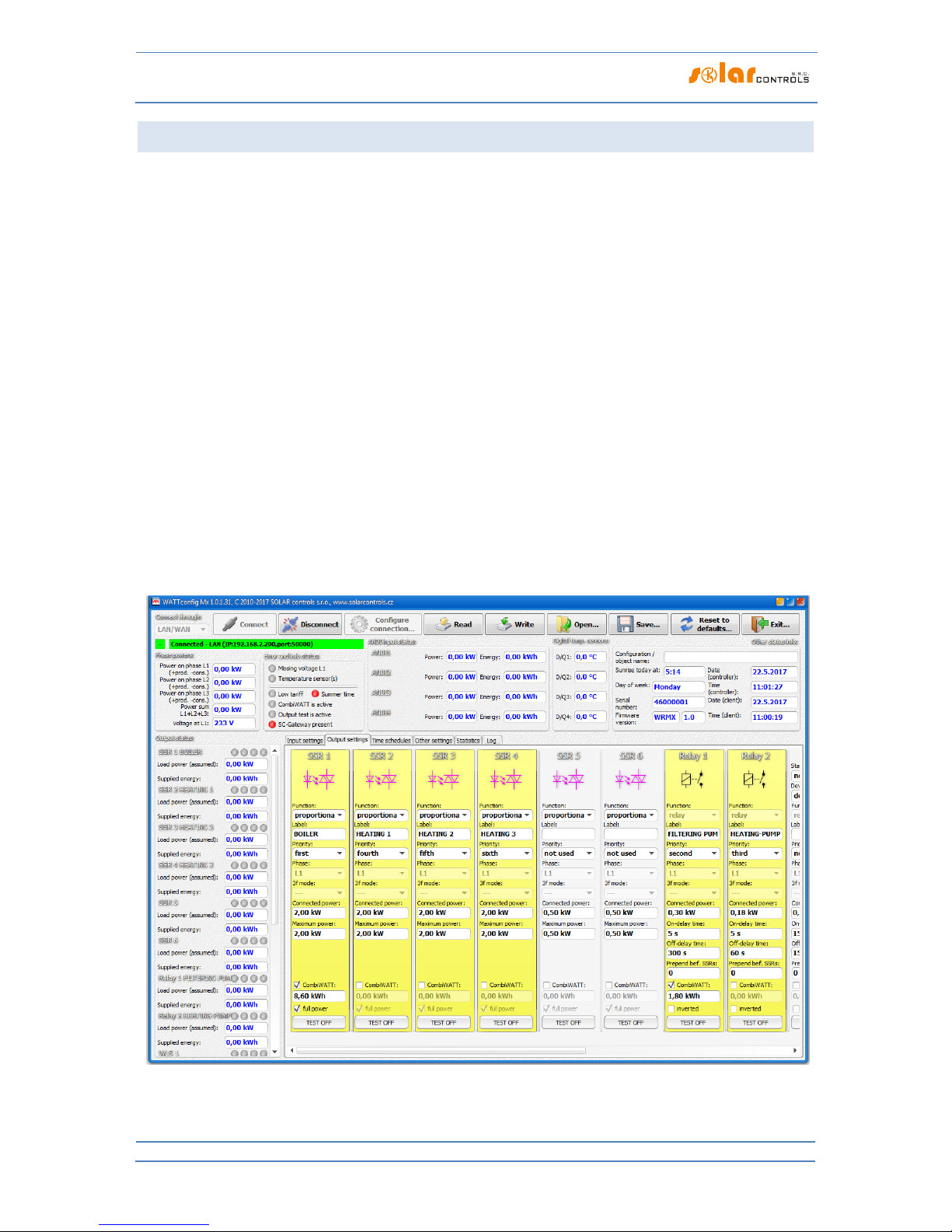
WATTrouter Mx - user manual
How to fit and setup the device
Page 55 from 82
EXAMPLE NO. 2 – 6 LOADS, CONTROL MOD E = SUM OF ALL PHASES
The same boiler as specified in example No. 1, swimming pool filtering pump and 6 kW instantaneous water
heating for the swimming pool (pump and three-phase heating element). Recommended peak power output of
the PV-plant is more than 8 kWp.
Boiler heating process has 1st priority (SSR1 No. 1).Requirements are the same as in example No. 1.
Filtering pump has 2nd priority (relay No. 1), nominal motor rating 0.3 kW (value in VA is usually not specified
here), and it must run exactly for 6 hours per day and the minimum switching time is 5 minutes. The daily
amount of required power for this motor is 1.8 kWh. If there is not sufficient amount of sunshine available, the
system will switch back to the low tariff. The motor should not be running at night between 23:00 and 5:00 not to disturb people during night (this also depends on the local low tariff time schedule so that the motor can
get a chance to run). If the boiler is large enough and does not often turn off by thermostat, we can set the
“Prepend before SSR” condition to 1 for the filtering pump to make better use of surpluses.
Heating pump has 3rd priority (relay No. 2), power output 0.16 kW and it must run always if the heating
element of the pool heating is on. The typical off delay time for the pump is 1 minute. We only want to turn the
swimming pool heating when there is surplus energy available. Make sure swimming pool heating is fitted with
a thermal protection!
Heating elements are connected to the remaining outputs with lower priorities (SSR outputs).
We recommend using separate contactors for motors, but due to their low power consumption rate it is not
really necessary. WATTrouter device uses low tariff signal and the boiler and swimming pool filtration motors
operate under CombiWATT mode.

WATTrouter Mx - user manual
How to fit and setup the device
Page 56 from 82
Time schedule for boiler is set the same as in example No. 1.
Two time schedules are assigned for pool filtering pump. The first of them describes restriction of the output
during "daytime" between 8:00 and 23:00. This restriction ensures the motor runs approximately 6 hours
(1,8kWh / 0,3kW) and therefore, it applies only if the output energy counter (field Supplied energy) exceeds 1.8
kWh. The second time schedule restricts operation of the motor between 23:00 and 5:00 without any special
requirements or conditions. The necessary prerequisite for correct application of these two time schedules is
correct configuration of daily energy counter reset. As reset mode there must be selected "at sunrise" or "at
fixed time". The fixed time for second case should be selected in the morning before 8:00.

WATTrouter Mx - user manual
How to fit and setup the device
Page 57 from 82
EXAMPLE NO. 3 – 7 LOADS, CONTROL MOD E = EA CH PHASE IND EPENDEN TLY
Loads specified in example No. 2 but more complex connection. Control mode is set for each phase
independently. In this example, it is necessary to distribute the appliances as uniformly as possible to the
individual phases, which is more complex and rarely can be done optimally.
Connect the following to L1 phase:
- boiler has 1st priority (SSR No. 1).Requirements are the same as in example No. 1.
- pool filtering pump has 2nd priority (relay No. 1).Requirements are the same as in example No. 2. Again we
can set the “Prepend before SSR” condition to make better use of PV-surpluses.
Connect the following to L2 phase:
- heating pump has 1st priority (relay No. 2).Requirements are the same as in example No. 2.
- 1st heating coil with 2nd priority (SSR No. 2).
Connect the following to L3 phase:
- auxiliary contact with 1st priority (SSR No. 5 operating as a relay), will also turn on the heating pump
connected actually to phase L2 (here, a small amount of power may be drawn from the public grid at phase L2,
but in order to prevent it we would have to use two circulation pumps).
- 2nd heating coil with 2nd priority (SSR No. 3).
- optionally also the 3rd heating coil in the 3rd priority (SSR No. 4), however, only if the assumed PV-power at
this stage is enough and it pays to buy another SSR.

WATTrouter Mx - user manual
How to fit and setup the device
Page 58 from 82
Time schedules are the same as in example No. 2.

WATTrouter Mx - user manual
How to fit and setup the device
Page 59 from 82
EXAMPLE NO. 4 – 5 LOADS, CONTROL MOD E = EA CH PHASE IND EPENDEN TLY
Boiler and pool filtering system specified in example No. 2 plus 2 resistive electric heaters and a heating pump
used to heat the swimming pool. Everything in more complex connection plus control mode set for each phase
separately.
Each electric heater draws 2 kW and should be powered only with the PV-surplus energy, independently of the
house hold primary heating system. These heaters must be deactivated at summer time - either through built
in thermostats, by deactivating fuse switches for respective outputs or by deactivating them in the software.
The heating pump draws power of 1.3 kW and it is powered only with the PV-surplus energy, or manually,
independently of the WATTrouter device.
Connect the following to L1 phase:
- boiler has 1st priority (SSR No. 1).Requirements are the same as in example No. 1.
- pool filtering pump has 2nd priority (relay No. 1).Requirements are the same as in example No. 2.
Connect the following to L2 phase:
- 1st electric heater with 1st priority (SSR No. 2).
- heating pump with 2nd priority (relay No. 2).
Connect the following to L3 phase:
- 2nd electric heater with 1st priority (SSR 3).
You may activate the ”Prepend before SSR” function for relay outputs, in order to better use the PV-surplus
energy at L2, when the heating pump and electric heater operate at the same time.

WATTrouter Mx - user manual
How to fit and setup the device
Page 60 from 82
Time schedules are the same as in example No. 2.

WATTrouter Mx - user manual
How to fit and setup the device
Page 61 from 82
ETHERNET NETWORK CON F IGU RAT ION
WATTrouter Mx allows monitoring and configuration via Ethernet socket. In order to establish the
communication you must correctly configure network connection.
Always entrust the configuration of the network and Internet access to the controller to a
person with the necessary technical skills. Problems associated with network settings, except
for demonstrable malfunctions of the regulator network interface, are not included in the
manufacturer’s technical support policy and cannot be claimed.
It is recommended to perform regulator network settings via USB interface (when you connect via Ethernet
and change network parameters you will probably always loose connection).
In order to successfully set network parameters you must know parameters of your local network. It is
necessary to know the following parameters:
IP address of your router or another access point to your local network (if it is installed),
Free range of IP addresses, which means that you need to know what addresses do not belong to the
range of dynamically assigned addresses, provided that your DHCP server is on and also what
addresses are not static addresses of other devices in your local network.
Local network mask used by all devices connected to your local network.
The controller allows you to set only static IP address. The controller does not support dynamic IP address
assignment because most users connect to the controller from Internet through a network router and its NAT
port mapper, for which static IP address is required.
LOCAL NE TWO RK CON NEC T ION SETTINGS
Network connection is configured in the "Other settings" tab, group "Network settings".
Network configuration changes will become effective only after you reset the regulator (see
option "Reset unit on config. write").
IP address: enter the IP address where regulator will be accessible. Make sure that the address does
not collide with other devices in your local network. For example, if the IP address of your router is
192.168.2.1, set it to 192.168.2.10, provided that this address is not already used by other device in
your local network and also provided that this address does not belong to the range of dynamically
assigned DHCP server addresses in your local network (DHCP server is usually active in your router).
Mask: enter the mask of your local network. In majority of cases the value is 255.255.255.0.
Default gateway: set IP address of network device where the controller will try to send requests
outside of your local network. In majority of cases it is the IP address of your router. In this case the
address is 192.168.2.1. If you do not have such device, enter another IP address not used in your local
network. In this case, requests directed outside of your local network will not be acknowledged.
Controller MAC address: enter the physical/MAC address of your controller. Change this value only if
there is another device with the same MAC address in your local network.
Note: WATTrouter Mx devices do not have their own IP address range registered within the IEEE,
because network communication is only additional feature and not the main function of the device. If
you change MAC address you must respect specific requirements applicable to these addresses!
UDP port: enter the value of the UDP port where the regulator will listen to incoming UDP requests
from WATTconfig software. Change this value only if there are several UDP servers in your local
network sharing the same UDP port, or if you want to increase protection against unauthorized access

WATTrouter Mx - user manual
How to fit and setup the device
Page 62 from 82
to your network. If you change UDP port in the regulator it is also necessary to change the UDP port
settings in the LAN/UDP driver configuration dialog.
HTTP port: enter the HTTP port value where your controller will listen to incoming HTTP requests -
that is requests from web browser. Change this value only if there are several web servers in your local
network (which will be accessible from the Internet), or if you want to increase protection against
unauthorized access to your network.
SE TTI NG UP INT ERN ET A CCE SS
In order to connect to the Internet we recommend you to have an active global static IP address. If you have
only dynamically assigned IP address, you may see its value in your router info page. Dynamic IP address may
also be used, but depending on your Internet connection provider, this address may vary more or less
frequently. If your controller is not accessible from the Internet, always check the WAN configuration in your
router first.
The controller may be accessed from the Internet only through routers or other access points which support
the NAT (Native Address Translation) function or other similar function, which is used to translate global IP
addresses and ports into local network IP addresses/ports.
The following text describes a sample Internet connection configuration, using a regular broadband router
Edimax BR-6204Wg-M. See the below:
On the NAT Settings tab check the field Enable NAT module function, and press Apply and then
Continue.
On the Port forwarding tab check Enable Port Forwarding, fill out the NAT table for as seen on the
picture and check Apply and then again Apply, which will save the settings in the router and your
router will restart.
NAT configuration is similar for other routers.
If your global address (static or the currently used dynamic address) is 80.200.50.6, then in order to access your
regulator from the Internet via HTTP protocol, enter the following address into your web browser (we
recommend creating a bookmark in your browser):
http://80.200.50.6/
In order to access your regulator from the Internet via WATTconfig, enter the same IP address into the
LAN/UDP driver configuration window, here 80.200.50.6.
If you experience conflict between HTTP ports, provided you have several web servers in your local network
which you want to be accessible from the Internet, it is necessary to select different HTTP port in the controller,
for example widely used alternate port No. 8080, instead of the standard port No. 80. To access the controller
then just enter the following address into your internet browser:
http://80.200.50.6:8080/

WATTrouter Mx - user manual
How to fit and setup the device
Page 63 from 82
DESCR IPTION OF WE B I N TER FAC E AND XML COMMUNIC ATI ON
WATTrouter Mx devices can be monitored and configured using regular Internet browsers. Web interface can
be used only if the controller is connected via Ethernet.
Figure18: Device web interface.
Using the web interface you may monitor and configure all controller parameters as if you would do using the
WATTconfig software, except for input checking oscilloscope, wireless network settings, time server testing,
statistic export/import, firmware upgrade and web client data exchange settings.
Web interface is implemented in your Internet browser by using AJAX/XML technology and therefore, you have
to allow JavaScript.
Monitoring the controller activity and configuring it may also be implemented into any superior control system
capable to send or parse XML data. However, the implementation requires certain knowledge of HTTP
protocols and XML files.
Authorization to write a new configuration was not designed using common HTTP authentication, but instead
of it the login data is embedded into each configuration write request. This mechanism simplifies the
implementation on the superior control system side where using HTTP authentication could be problematic.
In order to monitor and configure your controller you may use following HTTP/XML requirements. Description
of individual XML data are listed as HTML/XML comments directly embedded in the XML data listings:
1. GET /meas.xml

WATTrouter Mx - user manual
How to fit and setup the device
Page 64 from 82
By sending this HTTP request you will obtain the current measured/status data from the controller (actual
measured powers in individual phases and power/energy values for connected loads). Structure of
returned data:
<!--Response headers-->
<!--one empty line-->
<meas>
<I1>
<P>-2.20</P><!-- measured power by IL1 in kW-->
</I1>
<I2>
<P>1.50</P><!-- measured power by IL2 in kW-->
</I2>
<I3>
<P>-1.10</P><!-- measured power by IL3 in kW-->
</I3>
<I4><!-- ANDI1 input status-->
<P>0.50</P><!-- measured power in kW or temperature in °C-->
<E>1.60</E><!-- energy counted in kWh-->
</I4>
<!-- similarly for remaining inputs ANDI2(I5) to ANDI4(I7)-->
<O1><!-- SSR1 output status-->
<A>0</A><!-- assigned ANDI input (1 to 4) or 0 when unassigned-->
<P>1.00</P><!-- load power in kW-->
<E>3.00</E><!-- supplied energy to connected load in kWh-->
<HN>1</HN><!-- basic control mode: 0=inactive, 1=active-->
<HC>0</HC><!-- CombiWATT mode: 0=inactive, 1=active -->
<HE>0</HE><!-- output enforced by time schedule: 0=inactive, 1=active-->
<HR>0</HR><!-- output restricted by time schedule: 0=inactive, 1=active->
<T>0</T><!-- output test: 0=inactive, 1=active-->
</O1>
<!-- similarly for remaining outputs SSR2(O2) to WLS6(O14)-->
<DQ1>20.0</DQ1><!-- temperature measured by digital temp. sensor D/Q1 in
°C-->
<!-- similarly for remaining sensors DQ2 to DQ4-->
<PPS>-1.80</PPS><!-- sum of measured powers L1+L2+L3 in kW-->
<VAC>230</VAC><!-- voltage at L1 in V-->
<DaR>1.1.2017</DaR><!-- date (controller)-->
<TiR>0:00:00</TiR><!-- time (controller)-->
<CW>7200</CW><!-- time to activate CombiWATT-->
<DC>12.0</DC><!--internal DC source-->
<FW>1.0</FW><!-- firmware version-->
<SN>46000001</SN><!-- serial number-->
<EL1>0</EL1><!-- 0=no fault, 1=L1 voltage missing error-->
<ELV>0</ELV><!-- 0=no fault, 1=Wrong voltage value L1-->
<ETS>0</ETS><!-- 0=no fault, 1=temperature sensor(s) error-->
<EDC>0</EDC><!-- 0=no fault, 1=DC source overload-->
<ILT>0</ILT><!-- 0=not present, 1=low tariff active-->
<ICW>0</ICW><!-- 0=not present, 1=CombiWATT active-->
<ITS>0</ITS><!-- 0=not present, 1=output test active-->
<IDST>0</IDST><!-- 0=not present, 1=summer time-->
<ISC>0</ISC><!-- 0=not inserted, 1=inserted SC-Gateway module-->
<SRT>6:00</SRT><!-- sunrise time-->
<DW>1</DW><!-- day of week (0=Monday to 6=Sunday)-->
</meas>
2. GET /conf.xml

WATTrouter Mx - user manual
How to fit and setup the device
Page 65 from 82
By sending this HTTP request you will obtain the current configuration stored in the controller (input and
output settings, etc.). Structure of returned data:
<!--Response headers-->
<!--one empty line-->
<conf>
<DE>My configuration</DE><!-- configuration/object name-->
<I1><!-- IL1 input configuration-->
<N>IL1</N><!-- input label, for ILx inputs cannot be changed-->
<F>0</F><!-- input function (0=power meas. to 3=PT1000), for ILx inputs
cannot be changed -->
<Ph>0</Ph><!-- input phase (0=L1 to 2=L3)-->
<CD>0</CD><!-- current orientation (0=normal, 1=reversed)-->
<M>1</M><!-- conversion ratio of external CTs - multiplier-->
<D>1</D><!-- conversion ratio of external CTs - divider-->
..<O>0.00</O><!-- energy offset v kWh, only for ANDI inputs-->
..<Pu>1000</Pu><!-- number of impulses per kWh, only for ANDI inputs-->
..<DS>0</DS><!-- measurement source: 0=unknown, 1=prod. L1, etc.-->
</I1>
<!-- similarly for remaining inputs IL2(I2) to ANDI4(I7)-->
<O1><!-- SSR1 output configuration-->
<N>BOILER</N><!-- output label-->
<F>1</F><!-- output function (0=relay, 1=proportional, 2=PWM)-->
<Pr>1</Pr><!-- output priority (0=unused to 14=fourteenth)-->
<Ph>0</Ph><!-- output phase (0=L1 to 2=L3)-->
<M>0</M><!-- 3f mode (0=none to 3=max(L1,L2,L3))-->
<Po>2.00</Po><!-- connected output power in kW-->
<PM>2.00</PM><!-- maximum output power in kW-->
<PN>0.00</PN><!-- minimum output power in kW, only for PWM function-->
<PI>500</PI><!-- PWM-I value, only for PWM function-->
<TO>15</TO><!-- on-delay time in s, only for relay function-->
<TF>15</TF><!-- off-delay time in s, only for relay function-->
<CE>0.50</CE><!-- energy limit for CombiWATT in kWh-->
<CF>0</CF><!-- full power for CombiWATT (0=no, 1=yes)-->
<PR>0</PR><!-- prepend before SSR (0=inactive to 13=max. output count)-->
<In>0</In><!-- inverted output (0=normal, 1=inverted)-->
<TS>0</TS><!-- number of displayed time schedules (0=none to 4=all)-->
</O1>
<!-- similarly for remaining outputs SSR2(O2) to WLS6(O14)-->
<TS11><!-- 1st time schedule for 1st output (SSR1)-->
<M>2</M><!-- mode (0=unused, 1=restricted, 2=enforced) + NT, energy and
temperature flags, day of week flags, details upon request-->
<N>15:00</N><!-- time From-->
<F>19:00</F><!-- time To-->
<P>100</P><!-- power in percent, only for proportional outputs-->
..<Li>8.60</Li><!-- energy limit-->
..<TI>0</TI><!-- assigned temperature input (0=D/Q1 to 7=ANDI4)-->
..<TT>60.0</TT><!-- temperature limit-->
</TS11>
<!-- similarly for remaining outputs and time schedules (a total of 54 time
schedules)-->
<DQN1>temp. boiler</DQN1><!-- D/Q1 sensor label-->
<!-- similarly for remaining digital temperature sensors-->
<RM>1</RM><!-- control mode (0=each phase independently, 1=sum of all
phases)-->
<PO>-0.10</PO><!-- power offset in kW-->
<PWM>0</PWM><!-- PWM frequency (0=10kHz to 5=200Hz-->
<VM>1</VM><!-- voltage calibration - multiplier-->
<VD>1</VD><!-- voltage calibration - divisor-->
<URC>0</URC><!--optimize internal relay consumption (0=no, 1=yes)-->

WATTrouter Mx - user manual
How to fit and setup the device
Page 66 from 82
<IP>...</IP><!-- controller IP address-->
<MSK>...</MSK><!-- controller subnet mask-->
<DR>...</DR><!-- default gateway IP address-->
<MAC>...</MAC><!-- controller MAC address-->
<HTTP>80</HTTP><!-- HTTP port-->
<UDP>80</UDP><!-- UDP port-->
<CWD>7200.0</CWD><!-- CombiWATT delay in s-->
<CWL>0.02</CWL><!-- CombiWATT production limit in kW-->
<CWR>0</CWR><!-- energy counter reset (0=at sunrise to 1=fixed time)-->
<CWT>6:00</CWT><!-- fixed time for energy counter reset-->
<LA>50</LA><!-- latitude in °-->
<LO>15</LO><!-- longitude in °-->
<STC>0</STC><!-- synchronize date and time with the client (0=inactive,
1=active)-->
<STS>0</STS><!-- synchronize date and time with time server (0=inactive,
1=active)-->
<DST>1</DST><!-- use summer time (0=inactive, 1=active)-->
<TZ>13</TZ><!-- time zone (0=GMT-12 through 25=GMT+14)-->
<TSIP>...</TSIP><!-- time server IP address-->
<DT>0</DT><!-- digital sensor type (0=DS18S20, 1=DS18B20)-->
<DFT>1</DFT><!-- default tab (0=Input settings to 4=Statistics)-->
</conf>
3. POST /conf.xml
By sending this HTTP request you will save the configuration in the controller. This configuration has the
same format as the GET /conf.xml command, but you must (can) also send additional data. Append the
configuration to the POST /conf.xml command and skip 1 empty line, so the request will look like this:
POST /conf.xml
<!--Request headers-->
<!--one empty line-->
<conf>
<!--the following shows configuration data structure as in the GET
/conf.xml request-->
<DaC>1.1.2012</DaC><!-- date (client)-->
<TiC>0:00:00</TiC><!-- time (client)-->
<UN>admin</UN><!-- username for authorization, mandatory item-->
<UP>1234</UP><!-- password for authorization, mandatory item-->
<UNn>home</UNn><!-- new username, only when change is required-->
<UPn>abcd</UPn><!-- new password, only when change is required-->
<RST>1</RST><!-- reset controller, only if required-->
</conf>
The controller will reply with the following:
<!--Response headers-->
<!--one empty line-->
<conf>
<accept>0</accept><!-- error code: 0-ok, 1-incorrect configuration, 2incorrect login (access) data, 3-incorrect new login data, 4-wrong XML file
format-->
</conf>
4. POST /test.xml
By sending this HTTP request you activate or deactivate test mode for given output(s). Append the data to
the POST /test.xml command and skip 1 empty line, so the request will look like this:
POST /test.xml

WATTrouter Mx - user manual
How to fit and setup the device
Page 67 from 82
<!--Request headers-->
<!--one empty line-->
<test>
<TST1>1</TST1><!-- activate test mode for SSR1 output (1=activate,
0=deactivate)-->
<!-- similarly for remaining outputs when test mode change is required for
them-->
<UN>admin</UN><!-- username for authorization, mandatory item-->
<UP>1234</UP><!-- password for authorization, mandatory item-->
</test>
The controller will reply with the following:
<!--Response headers-->
<!--one empty line-->
<test>
<accept>0</accept><!-- error code: 0-ok, 2-incorrect login (access) data,
4-wrong XML file format-->
</test>
5. POST /learn.xml
By sending this HTTP request you activate the search request for any digital temperature sensors
connected to the DQ data bus. Append the data to the POST /learn.xml command and skip 1 empty line, so
the request will look like this:
POST /learn.xml
<!--Request headers-->
<!--one empty line-->
<learn>
<LRN>1</LRN><!-- search for temperature sensors-->
<UN>admin</UN><!-- username for authorization, mandatory item-->
<UP>1234</UP><!-- password for authorization, mandatory item-->
</learn>
The controller will reply with the following:
<!--Response headers-->
<!--one empty line-->
<learn>
<accept>0</accept><!-- error code: 0-ok, 2-incorrect login (access) data,
4-wrong XML file format-->
</learn>
6. GET /stat_day.xml?day={index}
By sending this HTTP request you will obtain the daily statistics from the controller. The "index" parameter
specifies the selected day (0=today, 1=yesterday to 31=last saved day). Structure of returned data:
<!--Response headers-->
<!--one empty line-->
<stat_day>
<SDD0>2017-07-20</SDD0><!-- date today-->
<SDD{index}>2017-07-17</SDD{index}><!-- date selected day-->
<SDS1>0.00</SDS1><!-- surplus energy phase L1 in kWh-->
<SDH1>0.00</SDH1><!-- consumption normal tariff phase L1 in kWh-->
<SDL1>0.00</SDL1><!-- consumption low tariff phase L1 in kWh-->
<SDP1>0.00</SDP1><!-- production phase L1 in kWh-->
<!-- similarly for remaining phases L2 and L3-->
<SDS4>0.00</SDS4><!-- surplus energy all phases in kWh-->
<SDH4>0.00</SDH4><!-- consumption normal tariff all phases in kWh-->

WATTrouter Mx - user manual
How to fit and setup the device
Page 68 from 82
<SDL4>0.00</SDL4><!-- consumption low tariff all phases in kWh-->
<SDP4>0.00</SDP4><!-- production all phases in kWh-->
<SDO1>0.00</SDO1><!-- daily energy for output 1 in kWh-->
<!-- similarly for remaining outputs SSR2(SDO2) to WLS6(SDO14)-->
<SDI1>0.00</SDI1><!-- daily energy for ANDI1 input in kWh-->
<!-- similarly for remaining inputs ANDI2(SDI2) to ANDI4(SDI4)-->
</stat_day>
7. GET /stat_week.xml
By sending this HTTP request you will obtain the weekly statistics from the controller. Structure of
returned data:
<!--Response headers-->
<!--one empty line-->
<stat_week>
<SWD>2017-07-20</SWD><!-- date today-->
<SWS1>0.00</SWS1><!-- surplus energy all phases in kWh, yesterday-->
<SWH1>0.00</SWH1><!-- consumption normal tariff all phases v kWh,
yesterday-->
<SWL1>0.00</SWL1><!-- consumption low tariff all phases in kWh, yesterday->
<SWP1>0.00</SWP1><!-- production all phases in kWh, yesterday-->
<!-- similarly for the 2th to 7th last day-->
</stat_week>
8. GET /stat_month.xml
By sending this HTTP request you will obtain the monthly statistics from the controller. Structure of
returned data:
<!--Response headers-->
<!--one empty line-->
<stat_month>
<SMD>2017-07-20</SMD><!-- date today-->
<SMS1>0.00</SMS1><!-- surplus energy all phases in kWh, yesterday-->
<SMH1>0.00</SMH1><!-- consumption normal tariff all phases v kWh,
yesterday-->
<SML1>0.00</SML1><!-- consumption low tariff all phases in kWh, yesterday->
<SMP1>0.00</SMP1><!-- production all phases in kWh, yesterday-->
<!-- similarly for the 2th to 31th last day-->
</stat_month>
9. GET /stat_year.xml
By sending this HTTP request you will obtain the annual statistics from the controller. Structure of returned
data:
<!--Response headers-->
<!--one empty line-->
<stat_year>
<SYD>2017-07-20</SYD><!-- date today-->
<SYS1>0.00</SYS1><!-- surplus energy all phases in kWh, this month-->
<SYH1>0.00</SYH1><!-- consumption normal tariff all phases v kWh, this
month-->
<SYL1>0.00</SYL1><!-- consumption low tariff all phases in kWh, this month-
->
<SYP1>0.00</SYP1><!-- production all phases in kWh, this month-->
<!-- similarly for the 2th to 12th last month-->
</stat_year>

WATTrouter Mx - user manual
How to fit and setup the device
Page 69 from 82
10. GET /stat_alltime.xml
By sending this HTTP request you will obtain the all time statistics from the controller. Structure of
returned data:
<!--Response headers-->
<!--one empty line-->
<stat_alltime>
<SAD>2017-07-20</SAD><!-- counted from date-->
<SAS1>0.00</SAS1><!-- surplus energy phase L1 in kWh-->
<SAH1>0.00</SAH1><!-- consumption normal tariff phase L1 in kWh-->
<SAL1>0.00</SAL1><!-- consumption low tariff phase L1 in kWh-->
<SAP1>0.00</SAP1><!-- production phase L1 in kWh-->
<!-- similarly for remaining phases L2 and L3-->
<SAS4>0.00</SAS4><!-- surplus energy all phases in kWh-->
<SAH4>0.00</SAH4><!-- consumption normal tariff all phases in kWh-->
<SAL4>0.00</SAL4><!-- consumption low tariff all phases in kWh-->
<SAP4>0.00</SAP4><!-- production all phases in kWh-->
</stat_alltime>
DATA REC ORD FO R W EB C LIE NT BASED XML EX CHANGE
The structure of the periodically transmitted XML data record to the server (in the example shown this record
is being processed by /index.php on the server):
POST /index.php HTTP/1.1
<!--Request headers-->
<!--one empty line-->
<wrmx>
<meas>
<DaR>2018-08-20</DaR><!-- date (controller)-->
<TiR>0:00:00</TiR><!-- time (controller)-->
<SN>46000001</SN><!-- serial number-->
<I1>
<P>-2.20</P><!-- measured power by IL1 in kW-->
</I1>
<I2>
<P>1.50</P><!-- measured power by IL2 in kW-->
</I2>
<I3>
<P>-1.10</P><!-- measured power by IL3 in kW-->
</I3>
<I4><!-- ANDI1 input status-->
<P>0.50</P><!-- measured power in kW or temperature in °C-->
<E>1.60</E><!-- energy counted in kWh-->
</I4>
<!-- similarly for remaining inputs ANDI2(I5) to ANDI4(I7)-->
<O1><!-- SSR1 output status-->
<P>1.00</P><!-- load power in kW-->
<E>3.00</E><!-- supplied energy to connected load in kWh-->
</O1>
<!-- similarly for remaining outputs SSR2(O2) to WLS6(O14)-->
<DQ1>20.0</DQ1><!-- temperature measured by dig. sensor D/Q1 in °C-->
<!-- similarly for remaining sensors DQ2 to DQ4-->
<PPS>-1.80</PPS><!-- sum of measured powers L1+L2+L3 in kW-->
<EL1>0</EL1><!-- 0=no fault, 1=L1 voltage missing error-->
<ELV>0</ELV><!-- 0=no fault, 1=Wrong voltage value L1-->
<ETS>0</ETS><!-- 0=no fault, 1=temperature sensor(s) error-->

WATTrouter Mx - user manual
How to fit and setup the device
Page 70 from 82
<EDC>0</EDC><!-- 0=no fault, 1=DC source overload-->
<ILT>0</ILT><!-- 0=not present, 1=low tariff active-->
<ICW>0</ICW><!-- 0=not present, 1=CombiWATT active-->
<ITS>0</ITS><!-- 0=not present, 1=output test active-->
<IDST>0</IDST><!-- 0=not present, 1=summer time-->
<ISC>0</ISC><!-- 0=not inserted, 1=inserted SC-Gateway module-->
</meas>
<current_day>
<SDD>2018-20-08</SDD><!-- date today-->
<SDS1>0.00</SDS1><!-- surplus energy phase L1 in kWh-->
<SDH1>0.00</SDH1><!-- consumption normal tariff phase L1 in kWh-->
<SDL1>0.00</SDL1><!-- consumption low tariff phase L1 in kWh-->
<SDP1>0.00</SDP1><!-- production phase L1 in kWh-->
<!-- similarly for remaining phases L2 and L3-->
<SDS4>0.00</SDS4><!-- surplus energy all phases in kWh-->
<SDH4>0.00</SDH4><!-- consumption normal tariff all phases in kWh-->
<SDL4>0.00</SDL4><!-- consumption low tariff all phases in kWh-->
<SDP4>0.00</SDP4><!-- production all phases in kWh-->
<SDO1>0.00</SDO1><!-- daily energy for output 1 in kWh-->
<!-- similarly for remaining outputs SSR2(SDO2) to WLS6(SDO14)-->
<SDI1>0.00</SDI1><!-- daily energy for ANDI1 input in kWh-->
<!-- similarly for remaining inputs ANDI2(SDI2) to ANDI4(SDI4)-->
</current_day>
<last_day>
<SDD>2018-19-08</SDD><!-- date yesterday-->
<SDS1>0.00</SDS1><!-- surplus energy phase L1 in kWh-->
<SDH1>0.00</SDH1><!-- consumption normal tariff phase L1 in kWh-->
<SDL1>0.00</SDL1><!-- consumption low tariff phase L1 in kWh-->
<SDP1>0.00</SDP1><!-- production phase L1 in kWh-->
<!-- similarly for remaining phases L2 and L3-->
<SDS4>0.00</SDS4><!-- surplus energy all phases in kWh-->
<SDH4>0.00</SDH4><!-- consumption normal tariff all phases in kWh-->
<SDL4>0.00</SDL4><!-- consumption low tariff all phases in kWh-->
<SDP4>0.00</SDP4><!-- production all phases in kWh-->
<SDO1>0.00</SDO1><!-- daily energy for output 1 in kWh-->
<!-- similarly for remaining outputs SSR2(SDO2) to WLS6(SDO14)-->
<SDI1>0.00</SDI1><!-- daily energy for ANDI1 input in kWh -->
<!-- similarly for remaining inputs ANDI2(SDI2) to ANDI4(SDI4)-->
</last_day>
<all_time><!-- all time statistics-->
<SAD>2018-08-01</SAD><!-- counted from date-->
<SAS1>0.00</SAS1><!-- surplus energy phase L1 in kWh-->
<SAH1>0.00</SAH1><!-- consumption normal tariff phase L1 in kWh-->
<SAL1>0.00</SAL1><!-- consumption low tariff phase L1 in kWh-->
<SAP1>0.00</SAP1><!-- production phase L1 in kWh-->
<!-- similarly for remaining phases L2 and L3-->
<SAS4>0.00</SAS4><!-- surplus energy all phases in kWh-->
<SAH4>0.00</SAH4><!-- consumption normal tariff all phases in kWh-->
<SAL4>0.00</SAL4><!-- consumption low tariff all phases in kWh-->
<SAP4>0.00</SAP4><!-- production all phases in kWh-->
</all_time>
</wrmx>
The server responds with this message when successfully processed (if this message is received the controller
then increments the “Successful exchanges” counter in the Webclient based XML data exchange window):
<!--Response headers-->
<!--one empty line-->
OK

WATTrouter Mx - user manual
How to fit and setup the device
Page 71 from 82

WATTrouter Mx - user manual
How to fit and setup the device
Page 72 from 82
TROUB LESHOO TIN G
The following table shows the most frequent problems and usual solutions:
Problem description
Possible causes
Solution
The regulator has been fitted
according to the manual but
after you switch on the circuit
breaker no LED lights up or
flashes.
The circuit breaker is on
but the supply voltage is
missing.
Check or measure whether there is any
voltage between terminals L1 and N.
Regulator failure/defect
Replace the regulator or take it to repair.
The regulator has been fitted
according to the manual but
after you turn on the circuit
breaker the green LED quickly
flashes, the regulator does not
work and the WATTconfig
software shows BOOT firmware
version.
The regulator runs in the
boot mode without any
application firmware
Use the WATTconfig software and load the
newest firmware version or load the version
you prefer. In this scenario, you have to
load the application using USB or RS485
interface, which is not blocked by the
regulator access authorization.
The regulator does not
communicate with computer
The regulator has no
voltage
Check whether green LED PWR is on and
the regulator is powered.
Computer is not properly
connected with the
regulator
Check the USB/network cable connection,
try using different network cable, or try the
cable with different device (printer for
example).
If there is problem with network connection
you may have a problem with your router
or with other network components. Try to
restart your device or try to connect the
network cable to another port. Your device
may also be incorrectly configured - the
same applies to local network configuration
settings. Should you experience problems
contact a computer or network expert.
If there is problem with the USB connection
then always try the newest USB driver.
Computer cannot detect
connected regulator.
Check USB/network cable connection.
When USB device is being registered in your
PC, the yellow LED COM must flash
temporarily. If your network cable is
connected correctly, at least one LED on the
regulator network connector must be on.
USB interface driver was
not correctly installed in
your computer
Make sure the USB interface driver is
correctly installed and Windows device
manager detects it as a USB serial
converter.
USB interface driver is not
configured properly
Use the USB/COM driver configuration
window in WATTconfig and reset all
parameters back to default values.

WATTrouter Mx - user manual
How to fit and setup the device
Page 73 from 82
LAN/UDP interface driver
is not configured properly
Use the LAN/UDP driver configuration
window in WATTconfig to check the validity
of IP address and UDP port. Connect to the
regulator using USB in order to determine
the current network configuration stored in
the regulator (use the Other settings tab). IP
addresses and UDP ports must have the
same configuration.
The Log window records
communication errors
A very few communication errors is
considered a common status and it depends
on the actual load put on Microsoft
Windows OS, the local network, or on the
operating system running in the regulator.
However, if there are many errors inspect
the functionality of your PC, or it may also
be a conflict at the USB interface in your PC,
USB driver may be outdated or your
Ethernet may be overloaded or
malfunctioning. If you are connected to the
Internet, large occurrence of
communication errors (packet losses) is
considered normal status.
Overloaded Ethernet
Your local network or Internet connection is
temporarily out of order, overloaded with
other transfers, etc. Try to reconnect later
or ask a network expert for advice to
optimize your connection.
Regulator failure/defect
Replace the regulator or take it to repair.
Measured powers on ILx inputs
are not displayed or they are
displayed incorrectly
The current sensing
module is not connected
Connect the current sensing module
according to this manual.
Incorrect phase sequence
Make sure that for all ILx inputs the “Phase”
field is correctly set. Perform the settings
according to chapter Setting up main
function and check with Input checking
oscilloscope.
Incorrect current
orientation settings
Make sure that for all ILx inputs the
“Current orientation” field is correctly set.
Perform the settings according to chapter
Setting up main function.
The ANDI inputs are
configured incorrectly
Wrong configuration of ANDI inputs can
cause incorrect measurement of ILx inputs!
Disconnect all CTs or sensors from ANDI
inputs and check the ILx function. If
everything is OK then again connect the
sensors to respective ANDI inputs and
select their functions exactly according to
connected sensors.
Regulator or current
Replace the regulator and/or current

WATTrouter Mx - user manual
How to fit and setup the device
Page 74 from 82
sensing module defect
sensing module or take them to repair.
There are suspicious waveforms
shown in chart "Current wave
oscilloscope"
This is normal
During normal operation there may be
shown even "exotic" waveforms. Be sure
this is the real current flowing through the
phase wire, a superposition of currents
flowing through the connected appliances
which are not sinusoidal or their power
factor varies from one.
Positive measured power value
(production) differs too much
from the value on the inverter
display
There is connected some
load, which decreases this
value.
No defect
Inverter shows
approximate values, or
the status is not stable
No defect
Incorrect phase sequence
or incorrect current
orientation settings
Follow the steps specified in the previous
troubleshooting item.
Low tariff signal is missing
Low tariff signal is not
connected
Connect the low tariff signal to LT terminal.
You must connect the signal through an
auxiliary relay as specified in this manual.
Low tariff signal is not
active
Wait until the signal is active, or manually
test the auxiliary relay by switching it on
(some relays offer this option).
Regulator failure/defect
Replace the regulator or take it to repair.
ANDI inputs do not work
Input function set
incorrectly
For ANDI inputs it is absolutely necessary to
correctly setup input function according to
connected input device/sensor.
Measurement with
external current
transformers does not
work
Connect a compatible external current
measuring transformer, such as another
current sensing module or other
WATTrouter compatible CT. Also check the
Phase and Current Orientation settings
which should follow the same principles as
for the ILx inputs.
S0 impulse output from
external meter/inverter is
connected with reverse
polarity
Observe polarity of the device output
(energy meter, inverter).
Signal coming from the
output is an unsupported
impulse signal
Use only device with S0 impulse output
whose signal carries information about the
measured energy and has a minimum
impulse width of 1 ms. Signal parameters
are described in chapter Technical
specifications.
Connected analog
temperature sensor does
not work
Connect only compatible sensors according
to chapter Technical specifications. Select
ANDI input function that corresponds with

WATTrouter Mx - user manual
How to fit and setup the device
Page 75 from 82
the sensor type. Measure the sensor
resistance and voltage at the ANDI terminal
against the GND terminal. For NTC, the
resistance must be about 10 kΩ at 25 °C,
the voltage approx. 1.67 V. For PT1000, the
resistance of approx. 1100 Ω at 25 °C,
voltage approx. 0.35 V.
Regulator failure/defect
Replace the regulator or take it to repair.
Digital temperature sensors do
not work
Incompatible sensor
Use only compatible sensor with original
chip inside (DS18B20 or DS18S20).
Wrong connection
Connect according to the connection
information on the sensor. Do not connect
sensors where this information is missing.
Always connect in 3-wire way (i.e. with
power supply)
DQ data bus too long
Shorten the bus, test the sensors one at a
time. If they operate individually but all at a
time not, the DQ bus capacity is too high. In
this case, you can also try adding a 4k7
resistor between the DQ terminal and the
+5V terminal.
Sensor bad
The sensor may be damaged, measure the
sensor power consumption (from terminal
+5V) with a milliammeter, the input current
should match the sensor specification, i.e.
max. 2mA. A faulty sensor sometimes has
an increased power consumption and is
warming up (this is not a rule). If there are
more sensors on the sensor bus, try one at
a time and identify the faulty sensor.
DQ input failure
This is not probable but possible, especially
if the sensors work on a different device.
Replace the regulator or take it to repair.
The TEST button cannot be used
to switch on some of the
connected loads
The relevant load is not
connected or it is
connected incorrectly
Check the connection of the relevant load
and switch on the corresponding circuit
breaker or fuse switch.
The load is connected
correctly but cannot be
switched on
Check whether the load is fitted for
example with a thermal protection system
or a thermostat, which is currently off.
Output LED is defect or
there is another regulator
defect
Replace the regulator or take it to repair.
Outputs do not switch on as they
should
Output is not activated
Activate the output by setting the relevant
priority.
PV-plant does not provide
sufficient power output
Check whether there is enough surplus
energy available in respective phase wire or
sum of phases L1 + L2 + L3 is positive,

WATTrouter Mx - user manual
How to fit and setup the device
Page 76 from 82
depending on configured control mode.
Incorrectly set priorities or
connected power values
Check the priority settings of your loads and
connected power settings according to their
power ratings.
Incorrect settings of some
items in the Other settings
tab
Check the settings in the Power offset field.
Also check the CombiWATT production limit
field, which should be low.
You cannot download firmware,
even if you try repeatedly
Incorrect or corrupted
*.scf file
Load only original regulator firmware for
the WATTrouter Mx device.
Communication errors
Make sure that there are no problems with
the connection of the regulator to PC, or in
the PC alone (viruses etc.).
Regulator failure/defect
Replace the regulator or take it to repair.
Flashing red LED
The system detected error
status
Follow instructions in the LED statuses
chapter.
When the available surplus
energy is decreased, the SSR
output with higher priority is
switched off earlier than the
relay output with lower priority
This is normal
Relay outputs have always longer delay
when in the process of disconnecting. In
order to make sure that energy from the
power grid is not drawn unnecessarily, all
connected proportional outputs with higher
priority may be disconnected earlier than
the relay outputs with lower priority.
CombiWATT function runs even
if PV-plant produces power
This is normal
CombiWATT will be initiated even if during
the time specified in the CombiWATT delay
time field, no production is detected at any
phase wire, which may occur if the PV-plant
produces small amount of energy or if loads
with large power consumption operate for
long time and consume all available surplus
energy. If you want to eliminate this
behavior, increase the value in the
CombiWATT delay time field.
Solid state relay (SSR) does not
switch on
SSR is not connected
correctly
Check for proper terminal connection and
observe polarity of SSR control anodes.
Incompatible relay
Always use a SSR with zero cross switch and
minimum DC control voltage of 4VDC.
Regulator failure/defect
Replace the regulator or take it to repair.
SSR failure/defect
Replace the SSR.
Data in statistics don't
correspond with reality
This is normal
The data are indicative only; the device
does not have accurate data from
utility/billing meters. Furthermore, the
device may be configured improperly, i.e.
does not evaluate the same as your utility
meter does.
Statistics suddenly erased
This is normal
There was a date change in the regulator or
power failure during writing the history into
EEPROM. Statistics on SD card should be

WATTrouter Mx - user manual
How to fit and setup the device
Page 77 from 82
fine.
SC-Gateway module is inserted
in the regulator, but neither Link
LED nor PWR LED works
Incorrect inserting of
module
Remove and insert module once again
based on installation module manual.
Regulator or module
failure/defect
Replace the module or regulator or take
them to repair.
Wireless peripheral can’t be
registered, even after longer
period while connected. Window
Add wireless station is not
displayed.
Station out of signal range
Test the wireless peripheral so it is placed
temporary closer to the regulator. Once this
time it is detected, there is necessary to
extend signal range with signal repeater.
Consult this problem with technical
support.
Station is incompatible
It is different type of wireless peripheral,
which is not compatible with SC-Gateway
module.
Station is defective
Follow the installation manual for the
wireless peripheral.
SC-Gateway module does
not react
Reset the regulator and wait about 1
minute. Then repeat the network
registration procedure.
SC-Gateway module
failure/defective
Replace the module or take it to repair.
Wireless station does not switch
or switches incorrectly
Station out of signal range
Test the wireless peripheral so it is placed
temporary closer to the regulator. Once this
time it is detected, there is necessary to
extend signal range with signal repeater.
Consult this problem with technical
support.
Station is defective
Follow the station manual
SC-Gateway module does
not react
Reset the regulator and wait about 1
minute. Then test the function of the
peripheral.

WATTrouter Mx - user manual
How to fit and setup the device
Page 78 from 82
MA INTENANCE AN D R EPA I RS
The WATTrouter Mx devices have been designed as maintenance-free units, provided that they were
configured and fitted according to instructions specified in this manual. We recommend inspecting the
operation of the entire system at regular intervals (at least once in a month, for example, when inspecting the
status of the PV-plant). Focus mainly on the load switching process and heat dissipation.
Should you discover a defect which cannot be repaired according to instructions specified in the
Troubleshooting chapter, contact your distributor (applies both to warranty and post warranty repairs).
Defect on current sensing module is very improbable. In case of a defective regulator, you can send only the
regulator for repair or replacement. The current sensing module may still remain fitted without the regulator.
Even if electric currents flow through measuring coils, the module will not be damaged.
Never attempt to repair your device by yourself! If you do so, you are putting yourself at risk of electric
shock. Further, your entire warranty will be void!

WATTrouter Mx - user manual
How to fit and setup the device
Page 79 from 82
TECHNICAL SPEC IFICATI ONS
Parameter
Value, notes
Main parameters
Supply voltage
230 V, 50 Hz
Power consumption – stand-by mode
<3 VA
Power consumption – 1 relay output
0.4 W
Power consumption – all outputs switched on and
loaded with maximum allowable currents
4 W (this value does not include switching losses of
connected power SSRs)
Current measuring range
Mx: 0-20 A (±5%), 50 Hz (±5 %)
Mx 100A: 0-100 A (±5 %), 50 Hz (±5 %)
Voltage range
Mx: 230V (±5%), 50Hz (±5%)
Maximum steady currents allowed to flow through
current sensing module
0-40 A (±5 %), 50 Hz (±5 %)
Mx 100A: 0-125 A (±5 %), 50 Hz (±5 %)
Active power measuring accuracy
2% ± 0,05kW (further calibration possible)
Output and input parameters
Power supply terminals L1 and N
230 V, 50 Hz. L1 = phase wire, N = neutral wire
+12V terminal
+12V with respect to GND. It is used to connect
external semiconductor relays (common positive
anode) or supply of external PWM/0-10V converters.
Max. cons. 60 mA, depending on load, this voltage
can drop to 8V.
+5V terminal
+5V with respect to GND. Max. cons. 100 mA. It is
used to connect external semiconductor relays
(common positive anode) or as power supply for
digital temperature sensors DS18x20.
Y terminal
+1,67V with respect to GND. It is a center of a voltage
divider for connecting the measuring module or
current measuring transformers to the Ilx or ANDI
inputs. ANDI inputs must have power measurement
function.
Relay outputs
230 V, 50 Hz, max. 10 A, 2300 W (it is recommended
to connect load with cos(Φ) ≠ 1 via external
contactor)
Protection: Regular circuit breaker, type B
SSR outputs - to connect solid state relays SSR (S1-,
S2-, S3-, S4-, S5-, S6-)
<+2V or +12V with respect to GND, isolated from
power grid supply
SSR parameters: control DC min. 4VDC, SSR must
switch at zero (zero switch).
Protection: based on instructions specified in the SSR
relay manual, we recommend semiconductor fuses
SSR outputs – to connect devices with PWM function,
direct PWM output (S1-, S2-, S3-)
0V or +12V with respect to GND, isolated from power
grid supply
Output type: open collector
PWM parameters: carrier frequency 200 Hz to 10
kHz, duty cycle 0-100% in 1% steps

WATTrouter Mx - user manual
How to fit and setup the device
Page 80 from 82
Protection: based on connected device instructions
SSR outputs – to connect devices with PWM function,
direct output of 0-10VDC signal (S4-, S5-, S6-)
+2V to +12V with respect to GND, it means -10V to 0V
with respect to +12V terminal, isolated from power
grid supply
Output type: Sallen-Key filter
Voltage range: 0-10V in 1% steps
Output ripple: according to preset PWM frequency.
Protection: based on connected device instructions
IL1, IL2, IL3 inputs:
Accept only secondary currents from current sensing
module or compatible current transformers.
Maximum allowed voltage against GND terminal is
5.5 V.
Model Mx: max. 40 mA.
Model Mx 100A: max. 125 mA.
LT input
0 or +5 V with respect to GND, isolated from power
grid supply.
May be switched using regular relay outputs or
optocouplers with open collector, always against
GND.
ANDI inputs
Analog inputs. Maximum allowed voltage with
respect to GND is + 5.5 V. Isolated from power grid
supply.
Power measurement function: as inputs IL1 to 3, but
approx. 15 mA
S0 pulse counter function: 0 or +5 V with respect to
GND. Minimum pulse and gap width is 1ms.
NTC function: Supported is resistive temperature NTC
sensor 10k@25°C, measurement accuracy is ±2°C.
PT1000 function: Supported is platinum temperature
PT1000 sensor, 1k@0°C, measurement accuracy is
±5°C.
DQ terminal
Data bus to connect digital temperature sensors
DS18B20 or DS18S20, measurement accuracy is
±0.5°C.
USB Connection
USB 1.1/ USB 2.0, isolated both from power grid
supply and other control parts of the regulator, serial
communication parameters: 115200 Bd 8N1.
LAN Connection
10/100 Mbit/s, isolated from power grid supply
according to IEEE 802.3
RS485 A and B terminals
RS485, isolated from power grid supply. Serial
communication parameters: 115200 Bd 8N1.
Dynamic characteristics
Active power measuring period (effective values)
typically 600 ms (including averaging of SSRs being
switched-on)
Regulation dynamics (full scale) at SSR output with
function set to proportional control
typically 3 s (from 0 to 100 % of power output and
vice versa)
Relay output on-delay time
Programmable (minimum of 2s)

WATTrouter Mx - user manual
How to fit and setup the device
Page 81 from 82
Relay output off-delay time
Programmable (minimum of 2s)
Other parameters
Maximum diameter of wires connected to terminals
2.5 mm
Maximum diameter of wires passing through
measuring transformers
Mx type: 9 mm (including insulation)
Mx 100A type: 14 mm (including insulation)
Distance of the current sensing module and the
regulator
<2 m (longer wires are acceptable, but they reduce
the accuracy approx. by 0.2% per 2m)
Distance of the regulator and solid state relay
<10 m
Working position
Any
Mounting
Regulator: DIN 35mm or wall mounted using 2 screws
with round or sink head and with diameter of up to
6mm.
Current sensing module: DIN 35mm or wall mounted
using 1 screw with round or sink head and with
diameter of up to 6mm.
Overvoltage category
III
Electric strength
4 kV / 1 min (between power supply (L1, N) and
pluggable terminals, between power supply and relay
outputs R1 and R2, between power supply and
communication sockets)
Pollution degree
2
Operational temperature range
-20°C to +40°C
Storage temperature range
-40 °C to +80 °C
Protection (power supply)
B6A
IP code
Regulator and current sensing module: IP 20
Dimensions (WxHxD)
Regulator: 106x110x64mm (6 modules)
Current sensing module:
Mx type: 70x110x64mm (4 modules)
Mx 100A type: 91x90x65mm (5-6M)
Weight
Regulator:400g
Current sensing module:
Mx type: 100g
Mx 100A type: 250g
Noise level (including power SSRs)
0 dB(A). Passive cooling only, for power SSRs,
sufficient heat dissipation is required.
Battery for real-time backup
CR2032 lithium, usual lifetime> 6 years
Warranty period
36 months
RECYCLING
After the product life is over the product may be disassembled, recycled or disposed of at a save dumpsite.
Legal regulations regarding electronic waste treatment have to be observed in respective country.
Do not dispose in regular household waste!

WATTrouter Mx - user manual
How to fit and setup the device
Page 82 from 82
EU DE CLARATION OF CO N FORMIT Y
Company:
SOLAR controls s.r.o. (manufacturer name)
Brojova 25, Plzeň, 32600, Czech Republic(manufacturer address)
29109795 (manufacturer id)
Hereby declares that this product:
WATTrouter Mx, WATTrouter Mx 100A (product name)
WRMX 01/08/17 (regulator) and WT 02/10, WT 03/11 (current sensing modules) (type/model)
Designed for to optimize self-consumption of electric power produced by photovoltaic power plant (function)
To which this declaration relates is in conformity with the following directives, standards and other normative
documents, provided that it is installed, maintained and used in application for which it was made, in
accordance with relevant installation standards and manufacturer's instructions:
Directives:
LVD Directive 2014/35/EU
EMC Directive 2014/30/EU
Standards:
EN 61010-1:2010
EN 61000-3-2:2006+A1:08+A2:09
EN 61000-3-3:2008
EN 61000-3-11:2000
EN 61000-4-2:2009
EN 61000-4-4:2012
EN 61000-4-5:2006
EN 61000-4-11:2004
EN 61000-6-3:2007
Year of affixing the CE marking: 2017
Declaration issued:
Plzeň, April 1, 2017 Ing. Tomáš Krýsl, Company Executive
----------------------------------------------------------------------------------------------------------------------------------------
(place and date) (name, job title and signature of responsible person of the manufacturer)
 Loading...