


The
Solar CarouSol Kit
Cruising the ocean floor, one
hunts the other through a
kelp forest; the other flees.
Who... is hunting whom?
Intermediate ages 12+skill level -
Basic soldering & tools required
Solar powered
(no batteries needed)
1-2 hours build time
www.solarbotics.com 1-866-276-2687
solarbotics.com/products/60425/ DocRev: Sept 09 2018

Introduction
Inspired by Jules Verne’s book “20,000 Leagues under the Sea” this kit
matches a whimsical deap-sea submarine against a mysterious Giant
Squid.
But as is the case when man ventures into territories unfamiliar, is he the
hunter or the hunted? Hence the name of this kit is “Squid Hunting”,
implying that either can be viewed as the aggressor in this story.
This kit lets this question play out as a solar-powered diorama, with light
powering the submarine’s propulsion which spins the dueling pair around
a kelp forest rich with sea-life.
We have designed the Squid Hunting to be a self-activating, solarpowered sculpture. Unlike other solar-powered devices, our
SolarEngine technology allows us to extract useful energy from
light levels otherwise unusable by solar cells.
TM
In direct sunlight, activation happens in seconds. Indoors, in a
location like an interior office with fluorescent fixtures, you can
expect motion every 6 minutes. As long as there is sufficient light
to read by, this device still works, activating only when it has stored
enough power to create useable motion.
We hope you enjoy the little story our model tells, and have fun
with both the mechanical and electrical assembly. As with all
Solarbotics’ kits, we guarantee a successful “no-fear” build. Enjoy
the process even if you experience a broken or lost part. Contact
us, and we’ll set things right!
1

4 x Laser cut wood panels
PARTS LIST
1 x Rotation point
& screw
1 x 1.0cm
(3/8”) marble
1 x Spinning
surface
1 x 0.5cm
(3/16”) magnet
1 x Solar Engine:
1 x SolarEngine
circuit board
1381
Transistor
M
Miller SolarEngine1.3
C2
C1
D1
Solar
1 x Double-sided
sticky tape (DSST)
1 x 0.22F capacitor* 1 x 22µF capacitor*
* Don’t mix these two parts up! (See Step 1.2)
1 x 2.0cm
(3/4") counter-
balance bearing
2 x 30AWG
wire
2 x SCC3733 solar panel
1 x TR2222
NPN transistor
1 x Motor
1 x Propeller
1 x Diode
1 x MCP112-195
voltage trigger
TOOLS REQUIRED
White glue / wood glue
Wire strippers (30AWG capable)
2
Soldering Iron
Solder

ASSEMBLY STEPS
Start by assembling the SolarEngine. This clever circuit
Intro to soldering
allows solar energy to be harvested and used in low light
levels - much lower than is usually possible.
There is soldering required, so if you are new to the process,
review the “how-to” link on the right.
Step
1.1
transistor
trigger MCP112 (also looks like a transistor)
22 F capacitor (has paper tape on the legs)μ
0.22F capacitor
diode
circuit board
1.2
1. SolarEngine Circuitry
Collect your electronics, being:
Remove any tape from the parts
Install and solder the parts in as shown below. Pay particular attention to the
youtu.be/iGzXGtH3adw
capacitors. They are similar in physical size, but in fact are 10,000x different
electrically. 22µF installs near the middle, where 0.22F (220,000µF!) is at the end.
2222a
Transistor
(flat side
facing in)
MCP Trigger
(flat side
facing out,
in 1381 spot)
22μF
capacitor
(C2)
+
Diode (D1)
0.22F
capacitor
(C1)
-
SolarEngine
circuit board
MATCH the orientation markers on any marked leads. Anything with a stripe is negative (”-”), and are
installed in the hole nearest that symbol. These components do not work backwards!
Cut two 6.5cm (2.5”) pieces of wire (one of each color) and remove 3mm (1/8”) of
1.3
Polarity stripe
Front side
Back side, after soldering
insulation from each end. Place your solar panels face down and edge to edge as
shown.
We are wiring these in
parallel (+ to +, - to -), so
solder the positives of the
panels together, and the
negatives of the panels
together.
3

ASSEMBLY STEPS
We’re going to test the electronics
1.4
before final installation. Start by
temporarily soldering the remaining
wire to the SolarEngine to one of the
solar panels.
-
+
+
+
-
-
Locate the motor and solder it to the
1.5
SolarEngine as shown. Pay close attention
to the color of the wire!
BLUE motor wire...
RED motor wire...
Don’t cross up the motor wiring. It will still work, but your model will spin backwards!
Let’s test the propulsion setup to
1.6
make sure all is good. Gently press the
prop ~1mm onto the end of the motor
as shown. Backwards, it still works, but
with only about half as much thrust.
Place the solar panels under direct
sunlight or incandescent light and wait
2-8 minutes, with the motor/prop free to
spin. When it activates, you should feel it
push air away from the motor. If not,
reverse the motor wire connections.
Install the prop with the small diameter on the
propeller hub facing away from the motor.
If you haven’t seen any action after 10
minutes, consult the Troubleshooting
desired
air flow
smaller diameter
section.
If all tests out okay, remove the
bigger diameter
propeller from the motor, which will
make final assembly easier.
-
+
These connections
are temporary
Desolder the temporary wires from the solarcell that connects the solarcell pair to
1.7
the Solarengine. We will later thread these wires from the solarengine through the
framework back to the solarcells during final assembly.
4

ASSEMBLY STEPS
Step
As the parts are all labeled and marked on the panel, the build is a simple process of
find, prepare, and assemble. The parts are cut so you only have to carefully rock them
out of the panel to break them free.
2.1
rings (1) and 6 squid arms (2-7) and
remove cutouts.
Match each arm into the mounting ring
slots, starting with squid arm (2), and
having all the remaining arms “flow” in
the same direction (limbs rearward).
2.2
arms (8-11), and the 3/4” ball bearing.
While cradling the ball in the cup formed
by the first set of limbs, slot the
remaining limbs around the bearing,
finishing the squid assembly.
2. Assembling the Squid
Remove the 2 squid mounting
Locate the the remaining 4 squid
Squid Arm Assembly
(1)
(1)
(2)
(3)
(4) (5)
(6)
(7)
(11)
With all two tentacles and 8 arms
2.3
(yup, we checked) installed, your squid
should look like this. Put him/her/it
aside, and we will start on the
submarine.
(8)
(9)(10)
bearing
bearing
5

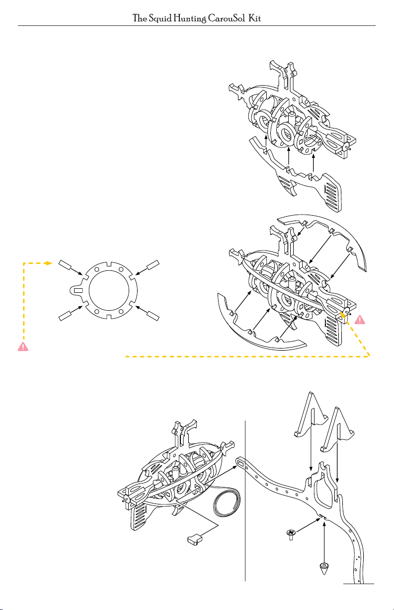
ASSEMBLY STEPS
Step
3.0
side-window portals (15) and remove any
stuck cutouts. Insert the sub windows into the
square holes on the sub rings.
3.1
and remove cutouts. Arrange the ring so it
slides over the portals and rests in between in
the middle.
3.2
remove cutouts. Mount it to the square pegs
at the end of the side portals so it sits tight
and snug.
3. Assembling the Submarine
Remove the submarine ring (12) and 2
The little “rivets” on the portal windows should face
outwards when properly assembled.
Remove the main submarine ring (13)
Remove the submarine ring (14) and
Mounting
Tab Side
To prepare the first rib for installation,
3.3
locate the top submarine rib (16) and motor
fin (17) and remove any cutouts. Slide the
motor fin onto the rib as shown.
6

ASSEMBLY STEPS
Locate the SolarEngine and
3.4
motor assembly. Slide the pager motor
into the slot created by the top rib and
motor fin.
The wires of the pager motor should be
straddling the fin on the top rib so one wire
is on each side when the motor is fully seated.
Feed the wires of the SolarEngine
3.5
through the ring assembly. You want your
wires to exit just ahead of the middle
mounting ring.
Finish with the SolarEngine module
sitting in the middle of the ring cavity.
Seat the top rib into the top slots of
3.6
rings, making sure the two are fully
mated together.
It’s important to keep the rectangular
mounting hole on the right side of the sub as
shown in the diagram.
Mounting
Tab Side
Mounting
Tab Side
7
ASSEMBLY STEPS
Remove the Bottom submarine
3.7
rib (18) and remove cutouts. Insert the
rib into the ring slots, making sure it is
fully seated.
Remove the remaining 4
3.8
submarine ribs (19) and insert them
into the slots of the sub rings, ensuring
they are fully seated.
The top ribs may install easier if you slide the
motor fin (17) out just a bit.
Step
4.0
solar panel holders (21), and
connector peg (22).
Mount the solar panel holders
into the slots on the balance
arm. Use the connector peg
to pin the submarine
to the balance arm as
shown (peg through sub,
then into balance arm).
Install the spin point and screw into
the balance arm slot. Finger tighten
them together into the slot.
4. Assembling the Balance Arm
Locate the balance arm (20), 2
(21)
(20)
(22)
8

+
-
+
-
ASSEMBLY STEPS
Complete the submarine by attaching the propeller back onto the motor like in
4.1
Step 1.6 on page 4 of this manual.
Start threading the wire-pair
4.2
through the balance arm. Leave
25mm (1”) slack at the sub to
allow easier SolarEngine access.
Leave 25mm (1”)
Feed the wire through the small
holes along the balance arm. These
wires will be used to connect the
solar panels to the SolarEngine in
the next step.
Snug the wires tight from hole-tohole on the balance arm for a clean
appearance.
Re-attach the solarcell wires (check
4.3
Step 1.4). You may trim any excess wire
to tidy up the installation, but you can
simply tuck excess up underneath
during final assembly.
Thread wires through
holes and snug up
slack
Continue the solarcell assembly by
4.4
sliding one of the solarcells through the
slot in the middle hole.
9

ASSEMBLY STEPS
Locate the magnet holder (23) and
4.5
the magnet. Position the magnet into the
circular cutout and slide the magnet
holder up and around it, trapping it in
place.
Cut four 3mm (1/8”) wide strips
4.6
from the double sided sticky tape. Peel
the protective paper off and mount the
solar panels to the panel holders.
Hide any extra wire in behind the panels.
With the sub and balance arm
4.7
complete, complete the “main
characters” assembly by slotting the
assembled squid into the slot at the
bottom of the balance arm.
10

ASSEMBLY STEPS
Step
5.0
5. Assembling the Tower
Remove the kelp tower arms
(24-29) and fish (30-33) and remove
any stuck cutouts. Place the fish into
their positions.
(32)
(30)
(31)
(30)
(27) (29) (26) (25)(24)
Locate the tower ring (34) and
5.1
install each kelp frond into the slots as
numbered below, starting with (24). The
other short frond (27) must go directly
across from it.
(27)
(26) (28)
(33)
(30)
(36)
(25)
(24)
(24)
Locate the tower base (35) and
5.2
tower cap (36) and remove cutouts.
Install the kelp frond assembly into
the base. The base slots ensure the
tall fronds line up properly with the
tower cap.
Align and install the tower cap, and
press the whole assembly vertically
together.
(29)
(35)
11
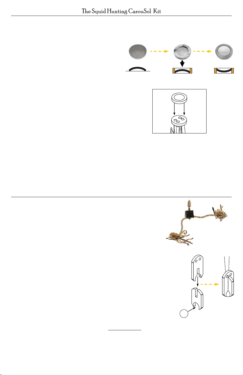
ASSEMBLY STEPS
Find the spinner surface and place
5.3
it face down (dome up) on a hard surface.
Place the spinner ring (37) over the
dome, and press it on so it “force fits”
onto the dome with edge of the spinner
dome flush with the ring.
Flip the spinner surface over, and
5.4
dome
side up
press ring
down onto
dome...
generously glue the assembly to the
tower cap.
Finish your project by balancing the arm on the spinner surface, and give it
5.5
some light. Within minutes, the prop will come alive, powering your undersea
pursuit. Have fun with your kit!
ADDITIONAL ENHANCEMENTS
...flip over!
Optional Ceiling Hang-point:
Suspend your “Squid Hunting” from the ceiling,
especially if you have a skylight or light-fixture nearby
(our tests show 7 minute cycles near an office
fluorescent fixture).
Build the suspension point with the holder (38), catch
(39), and steel bearing. Insert the bearing into the
holder, slide the catch down to trap it in, and hang it up.
Lift the “Squid Hunting” up to the ball, and the magnet
will easily suspend the assembly.
Select the hanging location carefully. A fall from ceiling
height will most likely end disastrously for the kit!
A drop of oil on the rotation point dramatically increases coasting “spin time”.
Feel creative? After everything is assembled and tested, paint the CarouSol kit
however you like! But do avoid the solar cell, electronics and spinning
surface/spinning point.
12
(39)
(38)
bearing

TROUBLESHOOTING
First, the Basics:
The SolarEngine powering the motor depends
directly on light intensity. Test with sunlight or
under an incandescent or halogen (not
fluorescent) lamp. If you have a voltmeter,
check that the voltage on the solar cells is
slowly climbing.
A bad solder connection is the most often
reason for a circuit failure. Inspect your
soldering for parts not connecting (too little
Good solder joint should look like this:
solder) or parts connecting when they
shouldn’t be (too much solder).
SolarEngine troubleshooting:
The easiest mistake is mistaking the transistor for the MCP, because they look the
same. Read the labels on the parts to make sure they haven’t been swapped.
Backwards components don’t work. Double-check their orientation. Find one? Use
a solder-sucker or solder braid to remove the solder , wiggle it free, and reinstall.
Are your solar panels connected correctly? They are like batteries, and won’t power
your project if either (or both) are connected backwards.
No flow from leg to pad
No flow from leg to pad
Solder “bridge” across pads
Flows from leg to pad
It’s not sitting horizontal:
Check for missing or extra parts and cut-outs. The balance was carefully designed,
and an extra bit will throw off the balance.
If necessary, add a small scrap of extra wood to the submarine or squid until it’s
balanced, and glue them in place in a hidden area.
The submarine is tipped forwards or backwards:
Ensure the rotation point is installed right in the middle of the balance arm. If you
need further adjustment, loosen the rotation point and slide it a bit to the low side
to help correct the fore/aft balance.
Is everything installed? Missing parts can easily cause a shift in balance.
Any forgotten cut-outs you forgot to remove? They also affect the balance.
The submarine travels backwards when the SolarEngine activates:
Your submarine has the propeller mounted on the back, and should push it
forward. Only reversing the motor wires will make it travel the right direction.
13

Liked “Squid Hunting”?
Check out our other dynamic kits:
The
Paris Flyer
Solar CarouSol Kit
Elegant airship travel cleverly
powered with SolarEngine
Technology
TM
The GraviTrack
Marble lifting motion feature two arms
and an elegant mid-flight hand-off.
Solar Edition Battery Edition

Build a deep-sea submirsible
No batteries - it’s solar powered! Build as a desktop or hanging mobile
Construct a lively kelp forest Assemble the Squid
Solarbotics “No Fear” Warranty
Aggressive feline interaction damage? Obtuse canine posterior oscillation disaster?
Plain old damage during construction? No issue. Contact support@solarbotics.com
and we’ll make sure you get the replacement parts (most often free of charge) to
have a successful build experience! We guarantee a successful build!
Visit us online for more info and cool stuff:
www.solarbotics.com
Questions or
comments?
Let us know!
This work is licensed under a
Creative Commons AttributionShareAlike 3.0 Unported License.
Solarbotics Ltd. is not responsible for any special, incidental, or consequential damages resulting from any breach of warranty, or under any legal
theory, including lost profits, downtime, good-will, damage to or replacement of equipment or property, and any costs or recovering of any material or
goods associated with the assembly or use of this product. Solarbotics Ltd. reserves the right to make substitutions and changes to this product without
prior notice. Keep out of reach of children.
© 2018 Solarbotics Ltd. All rights reserved. Parts, quantities, features and specifications are subject to change without notice. All other trademarks are
property of their respective owners. “SOLARBOTICS” is a trademark of Solarbotics Ltd. Reg. CIPO / USPTO.
Product contains small parts, even when assembled, that might be a choking hazard for children under five.
support@solarbotics.com
1-866-276-2687 (TOLL FREE)
MON-FRI, 9AM- 5PM MST
Warning: This product contains chemicals
known to the State of California to cause
cancer and birth defects or other
reproductive harm. See
P65Warnings.ca.gov for information.
3740D - 11A Street NE
Suite 101
Calgary, Alberta T2E 6M6
Canada
Made in Canada
 Loading...