


BrutusBotBrutusBot
Mobile Tank Platform
Get TANKED!
If you’re looking for an inexpensive, strong robot platform,
you’ll do well by the Tamiya Gearbox & Tread set and our
custom Aluminum base and Acrylic Top-Plate. It’s also
Arduino-template compatible!
www.solarbotics.com
1-866-276-2687
SKU: 60125
http://www.solarbotics.com/products/60125/
Document Revision: Nov 15, 2011

BRUTUSBOT
The BrutusBot
The Brutusbot is an affordable, customizable mobile tank
platform base. Being just a motorized base, you can add
any controller platform you desire, from something as
simple as a analog modified “Herbie” brain (yup, been
done!) to as complex as wireless Synapse networking
modules. The Acrylic shell is designed to mount any
Arduino-compatible footprint microcontroller
development platform, such as the standard Arduino
family, Freeduino, PICAXE-28 Project Board, and EZ-B.
Features Include:
Ÿ Rugged anodized aluminum chassis with skid plate
Ÿ Grippy Tamiya rubber treads for excellent traction
Ÿ Tamiya twin motor gearbox configurable for high-
speed (indoor / smooth environment) or high-torque
(outdoor / rough environments)
Ÿ Acrylic top-plate with cutouts for a sensor-sweeping
servo and pass-through wiring ports
Ÿ Acrylic top-plate works with Solarbotics S.A.F.E.
(Solarbotics Arduino Freeduino Enclosure) enclosure to
protect your electronics in off-road environments
Ÿ 6-cell 'AA' Battery Pack provides 9V to motors when
using 1.5V alkalines (7.2V using NiMH/NiCd)
Disclaimer of Liability
Solarbotics Ltd. is not responsible for any special, incidental, or consequential damages resulting
from any breach of warranty, or under any legal theory, including lost profits, downtime, good-will,
damage to or replacement of equipment or property, and any costs or recovering of any material
or goods associated with the assembly or use of this product. Solarbotics Ltd. reserves the right
to make substitutions and changes to this product without prior notice.
1

BRUTUSBOT
Parts List
(A)
(C)
(F)
(I)
(E)
(A) 1 - Tamiya Track and Wheel Set
(B) 1 - Tamiya Twin motor gearbox
(C) 1 - Velcro strap
(D) 1 - 6 cell ‘AA’ battery pack with 2.1mm male barrel jack
(E) 1 - Clear Acrylic top plate with cutouts
(F) 12 - 4-40 x 3/8" Panhead Philips Bolts
(G) 4 - 4-40 x 1 1/4" Hex Aluminum Standoffs
(H) 1 - Anodized blue aluminum chassis
(I) 4 - #4 x 3/16" Spacers
(J) 2 - #4-40 Hex nuts
(K) 2 - #2-56 x 5/8" Phillips 18-8 S/S Pan Head Machine
Screw
(J)(K)
(D)
(G)
(B)
(H)
Tools:
Assembly is quite straightforward, but you’ll still need:
Ÿ Soldering equipment (for wiring up)
Ÿ Wire cutters/strippers
Ÿ Philips #1 Screwdriver
Ÿ Needle-nose pliers
2

BRUTUSBOT
Assembly - The Top Plate
Important! There is protective brown paper on the acrylic.
Before you peel it off, read this page first!
Step 1 - Prepare the Top Plate: So
before you go willy-nilly and start
peeling paper, think about if you wish
to paint and customize your BrutusBot.
Yes? Read on!
No? Ok, peel away!
Painting acrylic is easy, especially when using a Krylon plastic paint
spray-bomb.
Peel off the larger portions and
leave the outline of the turret, then
spray two or three light coats (let
dry between coats). Or reverse the
effect by stripping off just the fine
lines.
Blue and Tan paintjobs
All but lines stripped
Here are a pair of topplates prepared with blue
and tan spray-paint.
These were prepared by
leaving the turret outline
papered during painting.
LED lights mounted
underside project the
turret’s outline onto the
ceiling.
3
BRUTUSBOT
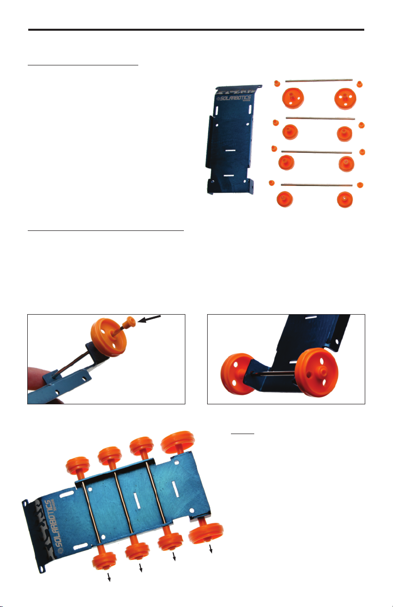
Assembly - THE CHASSIS
Step 2 - Chassis Parts: From the Tamiya Tread kit, find:
Ÿ 2 large idler wheels
Ÿ 6 medium sized idler wheels
Ÿ 4 idler axles
Ÿ 8 small idler shaft caps
Shaft
Also have the chassis on hand - it
Cap
the key part!
Chassis
Step 3 - Large Idler Installation: Make sure your large idlers don’t
have teeth - those are different parts!
Slide an axle through the holes at the far back of the chassis, away
from the logo / skid plate. Install one large idler, then push an
shaft-cap onto the axle until it stops moving. Then place the other
large idler on the other side and push on another shaft-cap.
Large
Idlers
Axle
Medium Idlers
Shaft-cap inserted onto axle Final Large-idler installation
Note: Sometimes the endcaps can get pushed on a
little too tight, and the
idlers rub against the
chassis.
If this is the case, give the
idlers on one side a gentle
tug to free up the idlers so
they can spin freely.
Nudge idlers to free up rotation
4

BRUTUSBOT
Assembly - THE GEARBOX
Step 4 - Gearbox Assembly: Make a decision now if you want a fast
but weak, or slow and strong BrutusBot, because it’s time to build
the gearbox! Converting it later is possible, but not that easy.
Want fast/weak? Built the Tamiya gearbox in ‘A’ (58:1 gear ratio)
configuration. Want slow/strong? Build ‘C’ (203:1 gear ratio)
configuration. Look at the
Tamiya twin motor
gearbox instruction
manual for details.
Note: The little blue tube that comes with the Tamiya twin motor
gearbox is a tube of grease. This is vital for stopping high-pitched
squealing from the gearbox!
Apply the grease in the locations shown in
the Tamiya instruction diagrams (darker
shaded spots on the gears & housing), and
especially to both sides of the inner hub of
the crown gear.
Grease the
crown gear!
Step 5 - Spur Gear installation: We prefer to use the large spur
gear, and designed the chassis to fit the treads using it. If you
really want to use the small spur gear, be our guest, but we can’t
guarantee the fit of the treads.
Push the spur gears onto your gearbox output axles until they don’t
travel any further (requires some force).
5
BRUTUSBOT
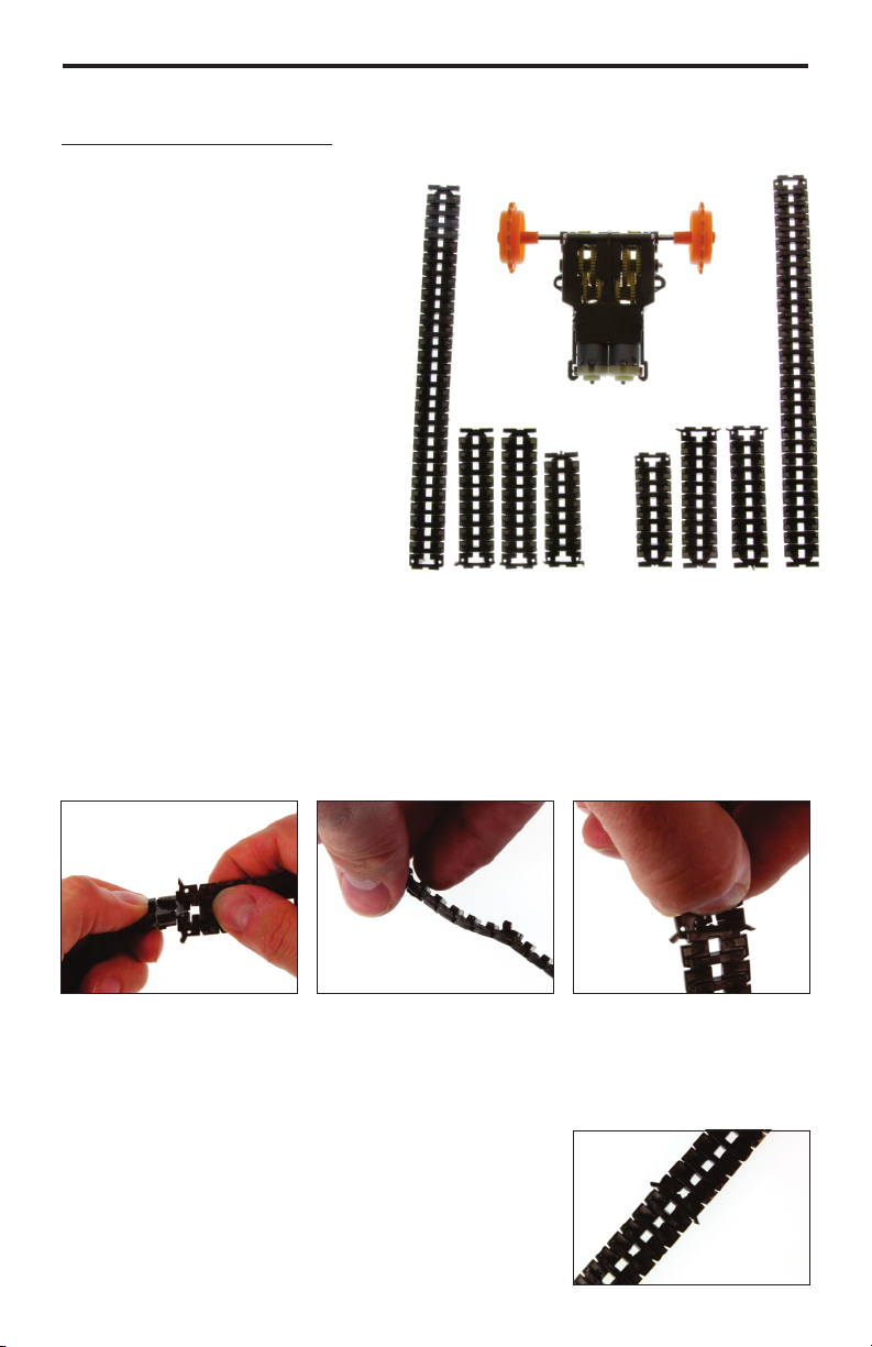
Assembly - The Tank Treads
Step 6 - Tread Assembly:
Each tread configuration requires:
Ÿ 1 long tank tread segment
Ÿ 2 medium sized segments
Ÿ 1 single short segment
Assemble the tracks as shown in section 3 in the Tamiya Track &
Wheel Set assembly instructions.
Tip: Having troubles linking the sections? After you get the first side
of the tread ‘T’ in place, fold the other side of the ‘T’ in half and
pass it through the hole
6a: Take the ‘T’ shaped
end of a tread segment
and place one side of it
through the hole of the
next segment.
6b: Place the nub from
the ‘T’ and slide it into
the link position.
6c: Use your thumb to
fold the other side of
the ‘T’ in half, and pass
it through the hole in
the other segment.
Now just finish placing the second nub
in place and repeat this process for the
rest of the segments you need.
6

BRUTUSBOT
Assembly - Mount The Parts
Step 7 - Gather the Hardware:
Find the bag of parts and hardware that
came with the Tamiya twin motor
gearbox, and locate the two #4-40
gearbox-mounting screws.
Use the Solarbotics-provided #440 nuts (they’re bigger and
stronger).
Step 8 - Mounting the Motor: If your motor is ‘A’ configuration
(speedy) , use the rear slots. ‘C’ configuration (torquey) uses the
front slots.
‘A’ Configuration uses REAR slots
Step 9 - Installing the Stand-offs:
The four 1-1/4” aluminum hex stand-offs
are bolted to the frame with the #4-40 x
3/8” screws.
Complete pre-tread Assembly
‘C’ Configuration uses FRONT slots
7
Hex stand-offs are mounted
with #4-40 x 3/8” bolts

BRUTUSBOT
Assembly - Install More Parts
Step 10 - The Battery Pack & Strap: Before it gets too snug, it’s a
good time to install the battery pack and strap.
The strap installs from the top through one slot, underneath (snug
against the frame, not the going over the axles), and back up the
other slot.
Power up your battery pack with batteries, place it on the chassis,
and strap it in!
Gather your frame, strap and battery pack
Thread the strap down through
the slot, and back up through the other
Secure battery pack down. Make sure battery wires
tuck behind the stand-off!
8

BRUTUSBOT
Assembly - The Final Countdown
Step 11 - Install the tank treads: Let’s make this look like a tank.
Slip the tank treads over each set of toothed spur gear and idlers.
Pull the twin motor gearbox forward, stretching the treads a bit,
and then let the gearbox pull itself back into place.
Shift the gearbox ahead ~ 1/8” (2mm) to keep some tension on the
treads, and then tighten up the gearbox mounting bolts. The treads
can’t dangle below the idlers - they have to sit tight, under tension!
Step 12 - Adding the top plate: Use your remaining #4-40 x 3/8
bolts to mount the acrylic top plate. Done! Let’s see it in action!
9

BRUTUSBOT
Choose Your Destiny
Step 13 - Installing your controller: The acrylic top plate has a
footprint for the classic Arduino hole pattern which matches the
Arduino UNO, Freeduino, PICAXE-28 project board or EZ-B. You can
attach the board via the extra [4] #4-40 x 3/8 bolts and nylon
spacers.
If you wish to use something else, use double sided sticky tape or
drill some holes. Acrylic is fragile and may crack when drilled with
regular high-speed bits, so try to use plastic-drilling drills at slow
speed (on a wood back-support), or a diamond-bit. We’ve even
resorted to using hot-glue for some projects (see “Herbert” below).
We’ve also included some #2-56 x 5/8” screws that can be used in
conjunction with the acrylic spacers to mount the servo up a little
higher when the twin motor gear box is in “C” configuration.
SB Freeduino
Arduino Uno
PICAXE-28 Project Board
EZ-B v3
“Herbert” Herbie modified BrutusBot
10

BRUTUSBOT
Troubleshooting & Wrap up
Hopefully, your Brutusbot is now up & running and happily causing
mayhem! If not, try these troubleshooting tips:
Brutusbot has a hard time moving: Low batteries, or it could be
that the end caps on the axles are installed too tightly.
Treads slipping off: Remember you need some tension in the
treads added by adjusting the position of the gearbox. Grippy
(carpet) surfaces also peel them off under lots of power. Adjust
your code to avoid spinning in place.
Gearbox is very noisy: More grease! Apply even more grease to
your gearbox, especially the faces of the gears that are near the
housing of the gearbox.
Funny behavior: Motor noise can cause problems. Add slight
motor delays to your code to compensate for electrical noise
generated by the motors. Also try adding 0.1µF filter capacitors on
the motors themselves between the motor leads, and from each
lead to the metal motor can (needs 3 capacitors per motor).
Can’t navigate tall grass: Be aware of the possibility of gear
teeth breaking if you place too much torque on the Brutusbot when
the twin motor gearbox is in the High speed ‘A’ configuration.
Please do not attempt off-road surfaces in high speed mode - it’s
best to use the ‘C’ configuration for more torque.
As with most kits, we encourage hacking and customizing the
original design and we look forward to seeing what you come up
with!
Visit us online for more info and cool stuff:
www.solarbotics.com
Solarbotics Ltd.
3740D - 11A Street NE, Suite 101
Calgary, Alberta T2E 6M6
Canada
This work is licensed under a Creative Commons
Attribution-ShareAlike 3.0 Unported License.
Made in Canada
Toll Free: 1-866-276-2687
International: +1 (403) 232-6268
Fax: +1 (403) 226-3741
 Loading...