


GB
User manual
Settings manual
PROMATIC D10
- mixing heating circuit controller
- direct heating circuit controller
- boiler controller
- d. h. w. heating controller
PROMATIC D20
- mixing and direct heating circuit controller
- d. h. w and sun collector heating controller
- heat pump system controller
- controller for two-boiler system, warmth
pump or a bivalent system
Heating controller
PROMATIC D10 and D20

CONTENTS
Introduction ....................................................................................................................... 4
USER MANUAL
DESCRIPTION ................................................................................................................. 5
D10 front panel ................................................................................................................. 5
D10 indicators of operation ............................................................................................... 5
D20 front panel ................................................................................................................. 6
D20 indicators of operation ............................................................................................... 6
GRAPHIC LCD DISPLAY ................................................................................................ 7
Description of symbols on display ..................................................................................... 7
DATA OVERWIEV .......................................................................................................... 10
Error messages ............................................................................................................... 13
OPERATION MODE AND TEMPERATURE SETTING ................................................. 14
Switch for selecting the operation mode ......................................................................... 14
Setting the required day temperature .............................................................................. 15
Setting the required night temperature ........................................................................... 15
Automatic setting of the required night temperature ....................................................... 16
Setting the temperature required d. h. w temperature. .................................................... 16
Manual one time turning on of d. h. w. warming............................................................. 17
Anti legionella program ................................................................................................... 17
Heating with combined boilers ........................................................................................ 17
SETTINGS MANUAL
THREE STEP SETUP .................................................................................................... 18
Heating curve .................................................................................................................. 19
MENU ............................................................................................................................. 21
Entering and navigating trough the menu ...................................................................... 21
Structure of the menu ..................................................................................................... 22
PROGRAM TIMER ......................................................................................................... 23
Selecting the program ..................................................................................................... 23
Viewing and changing the time program ......................................................................... 23
Changing the heating intervals................................................................................... 24
Adding new heating intervals ..................................................................................... 24
Deleting intervals ....................................................................................................... 24
Factory set time programs .............................................................................................. 25
User manual
2

CONTROLLER PARAMETERS SETTINGS .................................................................. 26
Rules for parameter settings and overview ..................................................................... 26
BASIC PARAMETERS ................................................................................................... 27
Setting the required day temperature ............................................................................. 27
Setting the required night temperature............................................................................ 27
Frost protection setting ................................................................................................... 27
Summer/winter switchover temperature.......................................................................... 27
MIXING HEATING CIRCUIT .......................................................................................... 28
Heating curve steepness ................................................................................................ 28
DIRECT HEATING CIRCUIT .......................................................................................... 28
Heating curve steepness ................................................................................................ 28
DOMESTIC HOT WATER .............................................................................................. 29
D. h. w .required temperature setti ng .............................................................................. 29
Sun collectors difference ................................................................................................. 29
HEAT SOURCES ........................................................................................................... 30
Minimum liquid fuel boiler temperature setting ................................................................ 30
Minimum solid fuel boiler temperature setting by D20 .................................................... 30
BASIC CONTROLLER SETTINGS ................................................................................ 31
Set language ................................................................................................................... 31
Set time ........................................................................................................................... 31
DEFAULT SETTINGS .................................................................................................... 32
CONTROLLER DATA .................................................................................................... 32
DECLARATIONS AND STATEMENTS ......................................................................... 33
Declaration of conformity ................................................................................................ 33
Warranty statement......................................................................................................... 33
Discarding old electrical and electronic equipment ......................................................... 34
NOTES ........................................................................................................................... 35
3
User manual

Thank you for buying a SOLARBAYER product.
We will try to further enhance your confidence by offering you quality products, information
and services.
It's important that you carefully read this operating instructions to be able to take full advantage of your appliance. Store this manual in a safe place as you never know when you might
need it again. When you will stop using the appliance, please discard it in a responsible way
that is not harmful to the environment.
INTRODUCTION
PROMATIC heating controllers are state of the art microprocessor controlled devices, manufactured in digital and SMT technology. PROMATIC D10 and D20 is intended for regulating
single boiler heating systems, remote heating, warmth pump and bivalent heating systems. It
is used for radiator, floor or convector heating as well as for d .h. w. warming. The controller
has a digital multichannel weekly programmable clock built-in which is used for timed programming of room and d. h. w. heating.
The PROMATIC
User manual
®
controllers are ensuring the maximum comfort and energy sav ing.
4

DESCRIPTION
D10 FRONT PANEL
2 4 5 6 1
3
1 7 8 9 10
USER MANUAL
1 - tightening screws
2 - LCD display
3 - setting the steepness of the heating
curve (DC* or MC** )
4 - setting the minimum temperature of
liquid fuel boiler
5 - info / Esc key
6 - navigation button for operating the
display
7 - setting the required day temperature
8 - setting the required night
temperature
9 - switch for selecting the mode
of operation
10 - setting the d. h. w. temperature
* **MC – mixing heating circuit
**DC – direct heating circuit
D10 INDICATORS OF OPERATION
1
2
5
If signal lamps 1, 2, 3, and 6 are flashing, that means, that a delay time to
switch off the indicated device is active.
3
4
6
1 - burner
2 - circulation pump of the direct heating circuit UWP2
- circulation pump for d. h. w. circulation BCP
3 - circulation pump of the mixing heating circuit UWP
- circulation pump for d. h. w. circulation BCP
4 - opening of the mixing valve (M+)
5 - closing of the mixing valve (M-)
6 - circulation pump for d. h. w. heating BLP
5
User manual

D20 FRONT PANEL
2 5 6 7 1
4
3
1 8 9 10 11
D20 INDICATORS OF OPERATION
1 - tightening screws
2 - LCD display
3 - setting the steepness of the heating
curve (MC* or DC** )
4 - setting the minimum temperature of
solid fuel boiler
- setting the start-up temperature
difference for sun collectors
- setting steepness of the heating
curve (DC** )
5 - setting the minimum temperature of
liquid fuel boiler
6 - info / Esc key
7 - navigation button for operating the
display
8 - setting the required day
temperature
9 - setting the required night
temperature
10 - switch for selecting the mode of
operation
11 - setting the d. h. w. temperature
**MC – mixing heating circuit
**DC – direct heating circuit
2
5
User manual
1 - burner
1
- heat pump
2 - circulation pump of the direct heating circuit UWP2
- circulation pump for d. h. w. circulation BCP
3
- circulation pump for sun collectors KTP
- boiler switching
3 - circulation pump of the mixing heating circuit UWP
- circulation pump for d. h. w. circulation BCP
4
- circulation pump for sun collectors KTP
4 - opening of the mixing valve (M+)
5 - closing of the mixing valve (M-)
6 - circulation pump for d. h. w. heating BLP
6
If signal lamps 1, 2, 3, and 6 are flashing, that means, that a delay time to
switch off the indicated device is active.
6

GRAPHIC LCD DISPLAY
DESCRIPTION OF SYMBOLS ON DISPLAY
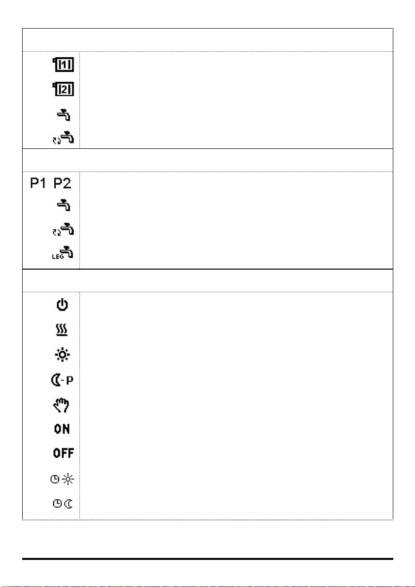
Symbols for temperature display:
Display of inside (room) temperature for MC – mixi ng heating circuit (RF).
Display of inside (room) temperature for DC – direct heating circuit (RF).
Outdoor temperature display (AF).
Mixing circuit stand-pipe temperature display (VF).
Mixing circuit return-pipe temperature display (RLF).
Direct circuit stand-pipe temper ature dis play .
Liquid fuel boiler temperature display (KF).
Return-pipe temperature return in the solid fuel boiler display (RLKF).
D. h. w. temperature display (BF1/BF2).
Solid fuel boiler temperature display (KF2).
Screed temperature display (EF).
D. h. w. circulation pipe temperature display (BF3).
Exhaust gas temperature display (AGF).
Heat accumulator temperature display (SF).
Sun collectors temperature display (KTF).
Measured temperature display.
Calculated or required temperature display.
Sensor error display (short circuit, open contact).
7
User manual
Symbols for heating circuitcs
Mixing heating circuit - MC.
Direct heating circuit - DC.
D. h. w. heating.
D. h. w. circulation.
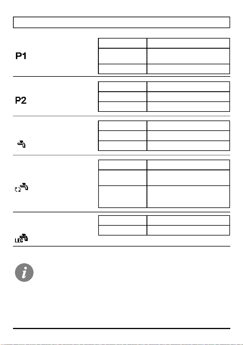
Time programs
Time programs for room heating P1 and P2.
Time program for d. h. w. heating.
Time program for d. h. w. circulation.
Time program for anti legionella function.
Symbols for operation mode indication
Switch off.
User manual
Heating turned on - automatic heating mode.
Day temperature heating operation mode.
Night temperature heating operation mode.
Manual operation.
D. h. w. warming or circulation – permanent switch on.
D. h. w. warming circulation– permanent switch off.
Room heating with time program on day temperature.
Room heating with time program on night temperature.
8

Request for heating on required day temperature “Party”
(activated on room unit).
Request for heating on required night (saving) temperature “ECO”
(activated on room unit).
Remote control of the heating.
Operation is active by time program (d. h. w., d. h. w. circulation).
Operation is not active by time program (d. h. w., d. h. w. circulation).
One time d. h. w. warming.
Anti legionella protection active.
Automatic switch to summer heating mode.
Devices connected to communication port COM.
Room unit DD2 connected
Controller and communication port COM/COM2 status.
Single controller.
Leading or first controller.
Following (slave) controllers - connected between
leading and last controller.
The last (slave) controller.
9
User manual
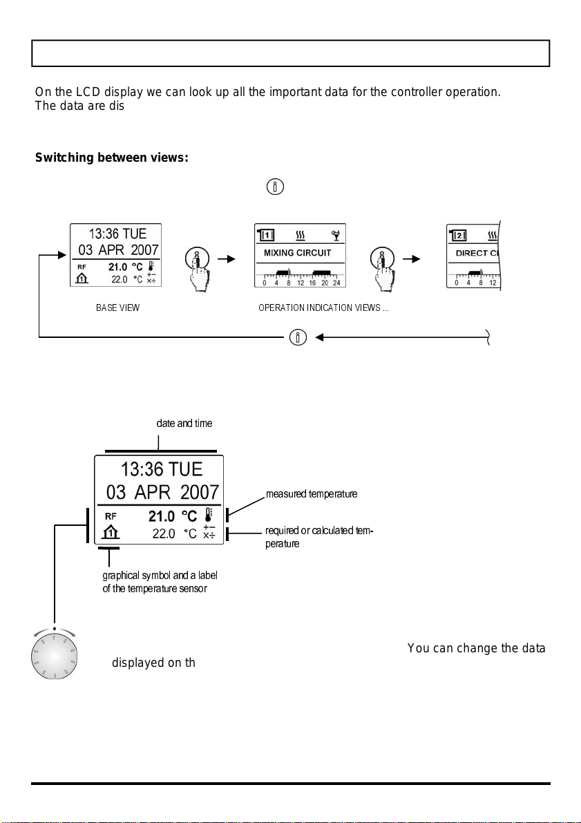
DATA OVERWIEV
On the LCD display we can look up all the important data for the controller operation.
The data are displayed on base and operation indication views.
Switching between views:
To switch between displays press the key .
BASE VIEW OPERATION INDICATION VIEWS ...
Description and presentation of the base view:
date and time
User manual
measured temperature
required or calculated tem-
perature
graphical symbol and a label
of the temperature sensor
On the base view is displayed the current information on all measured, calculated or required temperatures and some other data. You can change the data
displayed on the lower part of the screen by turning the navigation button.
10

ROOM TEMP. MC* ROOM TEMP. DC**
OUTDOOR TEMPERATURE
STAND-PIPE TEMP. MC*
RETURN-PIPE TEMP. MC* STAND-PIPE
D. H. W. TEMPERATURE
SUN COLLECTORS TEMP.
D. H. W. TEMPERATURE
FLOOR TEMPERATURE
CONTROLLER STATUS DEVICES ON COM PORT SELECTED SCHEME
TEMP. DC**
BOILER TEMPERATURE
SOLID FUEL BOILER TEMP.
D. H. W. CIRCULATION TEMP.
RETURN-PIPE TO THE BOILER
HEAT ACCUMULATOR TEMP.
EXHAUST GAS TEMPERATURE
Only data that is current for the chosen hydraulic scheme is displayed.
*MC – mixing heating circuit, **DC – direct heating circuit
11
User manual
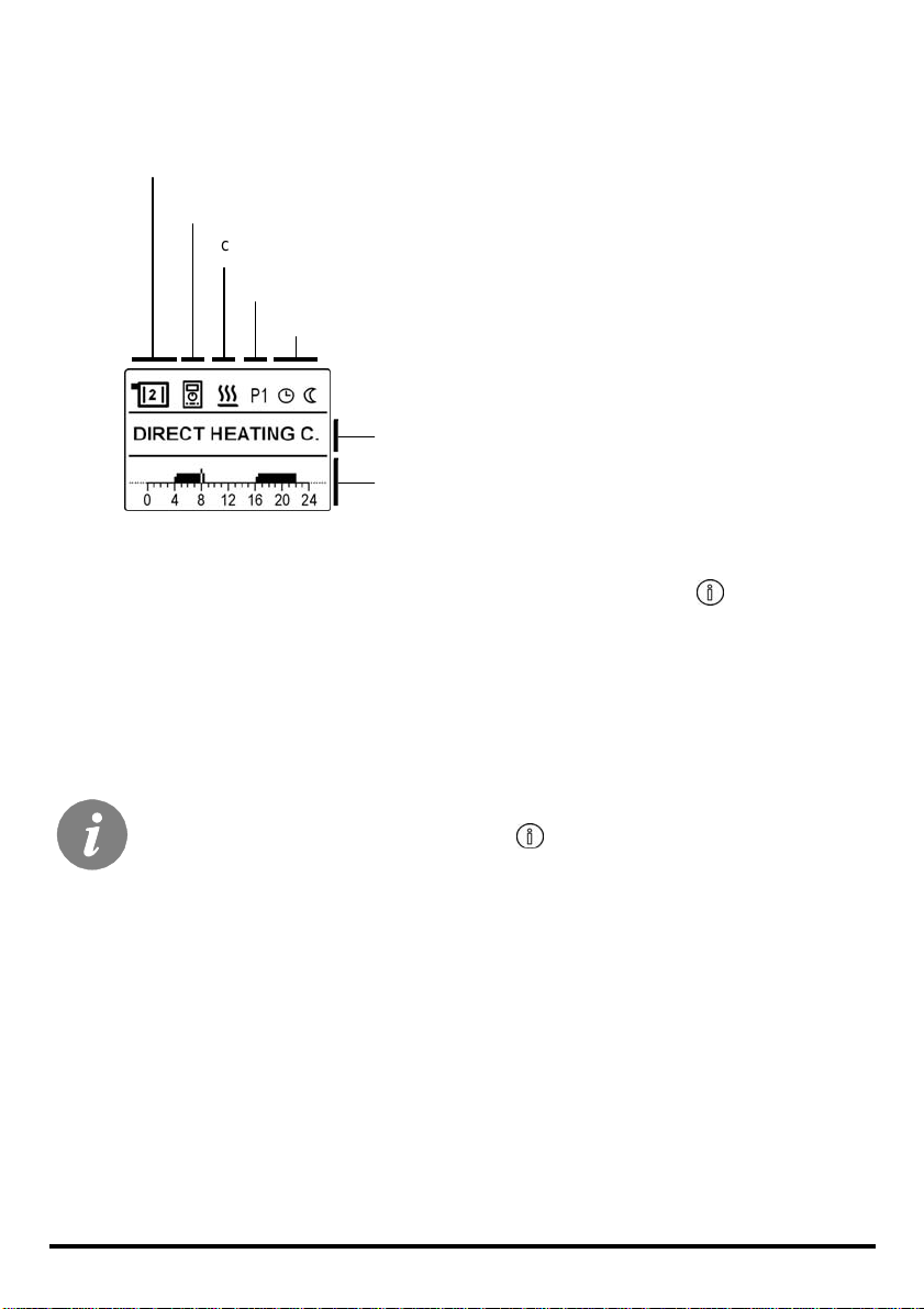
Description and presentation of the operation indication view:
heating circuit
heating circuit is controller by room unit
chosen operation mode
chosen time program P1 or P2 for room heating
current operational status
name of the regulated circuit
time program, displayed on a 24h timeline
You can change the indication views listed bellow by pressing the button :
- MIXING HEATING CIRCUIT
- DIRECT HEATING CIRCUIT
- DIMESTIC HOT WATER
- DOMESTIC HOT WATER CIRCULATION
User manual
Which information will be shown as default view can be set as follows: select
the desired display, press and hold the button for 2 s.
12
Selecting the P1 or P2 time program:
For the mixing and direct heating circuits there are two time programs (P1 and P2) available.
You can select the desired time program by pressing the navigation button. Mark P1 or P2
begins to flash. Now you can select the desired time program by turning the navigation button and confirm the selection with pressing the button again.
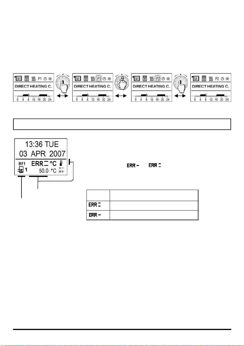
ERROR MESSAGES
If you notice any unexpected behavior of the controller, it is
probable that one of the sensors has broken down. You can
test the proper operation of the sensors in basic display by
turning the navigation button. If a sensor is not working properly, an indicator or appears next to its symbol
for temperature.
Temperature sensors status description :
Error message.
A sensor that is not
working properly.
- - -
- sensor is not connected
- cable or sensor is disconnected
- sensor short circuited
13
User manual

OPERATION MODE AND TEMPERATURE SETTINGS
SWITCH FOR SELECTING THE OPERATION MODE
With the switch for selecting the mode of operation you can select between 6 different
modes of operation. The selection is valid for those heating circuits, which are not controlled
with a room unit. Warming of domestic hot water is active, if the d. h. w. warming is activated
on the controller or room unit DD2.
Heating OFF: The operation mode switch is set in this position, if you
want to turn off the heating and d. h. w. warming at the end of a heating
season.
D. h. w. warming: The operation mode switch is set in this position, if
you want to turn off the heating at the end of a heating season and let the
d. h. w. warming turned on.
Room heating: Room heating is operating in accordance to the time
program P1 or P2 of the controller program timer.
User manual
Day temperature: Room heating operates dependent from setting of the
day temperature on the controller.
D. h .w. warming is turned on.
Night temperature: Room heating operates dependent from setting of
the night temperature on the controller.
D. h .w. warming is turned on.
Manual operation: This mode of operation is used for measuring the
smoke gases emissions or when the controller is broken down. Controller
turns on the burner and all circulation pumps.
14

When the switch is in a “manual operation” position, you can set the position of the mixing
valve by turning the button for setting nighttime temperature.
button position:
mixing valve: closing stand-still opening
SETTING THE REQUIRED DAY TEMPERATURE
You can set the required day temperature with this button. The temperature setting is reflected as a parallel shift of the heating curve. The daytime
temperature can be set in a span between 12 and 28 °C.
SETTING THE REQUIRED NIGHT TEMPERATURE
You can set the required night temperature with the button. The temperature setting is reflected as a parallel shift of the heating curve. The night
temperature can be set in a span between 8 and 24 °C.
15
User manual

AUTOMATIC SETTING OF THE REQUIRED NIGHT TEMPERATURE
You can set the automatic setting of the required night tempetaure by
turning the nighttime temperature setting button to the position “AUT”.
Due to the heat accumulation, the nighttime room temperature is usually
higher than the required temperature setting. It is important, that the building
is adequately heated even at that time, especially when the outdoor temperature is very low.
SETTING THE REQUIRED D. H. W. TEMPERATURE
You can set the required d. h. w. temperature with this button. The controller
heats d. h. w. in accordance with the time program.
Temperature of the d. h. w. can be set between 30 and 70 °C. You can turn the heating OFF,
or turn it ON independent from the time program.
Working thermostat on the boiler must be set on a temperature that is at least
10 °C higher than the preferred d. h. w. temperature.
User manual
16

MANUAL ONE TIME TURNING ON OF D. H. W. WARMING
The function “one time turning on the d. h. w. warming” is used when you need the d. h. w.
warming outside the time program.
Activate it by turning the button to the position ON and
back to the requied temperature setting after the beep.
When the function is activated, the symbol is
shown on the display.
ANTI-LEGIONELLA PROGRAM
The controller has a special built in function that heats the water to 66 °C to prevent legionnaries disease. You can switch on the anti-legionella program in the corresponding time
program. When the function is activated, the symbol is shown on the display.
Working thermostat on a boiler must be set on 75 – 85 °C (position 3).
HEATING WITH COMBINED BOILERS
When using a combined boiler (solid and liquid
fuel), you need to press a solid liquid key
(accessory) or turn the day temperature setting
button to the minimum setting and then back after
the beep. This way you can temporarily stop the
solid fuel burner.
When the solid fuel runs out, the liquid fuel burner
is turned on automatically after a certain period of
time. If you change your mind and want to start
burning liquid fuel immediately, you can turn the
night temperature setting button to the minimum
setting and then back after the beep.
17
User manual

SETTINGS MANUAL
THREE STEP SETUP
Heating controllers PROMA TIC D10 and D20 are equipped with an innovative procedure to
set up the controller in three easy steps.
STEP 1
When the co n tr ol l e r is tu r ned on fo r th e fi rst ti m e t he di sp l a y sho ws t he l og o an d t he p rog ra m
version. With turning the button select the desired language and confirm it with pressing the
button for 2 seconds.
2 s
STEP 2
In this step the hydraulic scheme is selected and confirmed with pressing the button for 2
seconds. By some hydraulic schemes you also can select floor or radiator heating mode.
2 s
STEP 3
With the buttons on the controller you should set up the minimal boiler temperature and the
heating curve steepness for the direct and (or) mixing heating circuits (button 3, 4 and 4 on
pages 4 and 5).
Settings manual
18

The hydraulic scheme can be changed every time.
This can be done as follows:
1. In the base view rotate the navigation button so long that you get to the scheme
preview. Than push and hold the button and the info button. When the scheme
number begins to flash, stop holding the buttons. With rotation of the navigation
button select the desired scheme and confirm it with pressing the navigation button.
2. The hydraulic scheme can also be changed in parameter S1.1.
3. You can retake the controller three step setup.
Restarting the three step procedure!
Unplug the controller from the power source. Press and hold the key info and recconect
the power supply. When the controller restarts itself, the 3 step procedure is activated.
HEATING CURVE
Heating curve steepness tells us, what temperature is required for the heating bodies by a
determined outdoor temperature. The steepness setting depends on the heat system type
(floor, wall, radiator, convector heating) and insulation of the building..
ADJUSTING THE HEATING CURVE STEEPNESS
If you have enough data, you can determine the heating curve steepness with a calculation,
otherwise from experience, based from the evaluation of heating system dimensioning and
building insulation.
The steepness is set correct, if the room temperature remains stable, even by large outdoor
temperature changes.
Until the outdoor temperature remains above + 5 °C , you can adjust the day / night temperature with k e ys on the ro om un it. I f i t get s co l d er in th e b uil di ng , whi l e t h e out d oo r te mp e ra tur e
is dropping, then the heat curve steepness is set to low - you should increase the setting. If
the object by low outdoor temperatures gets warmer, the heat curve steepness needs to be
decreased.
The maximum steepness increase/decrease should not be greater than 0,1 to 0,2 units at
one observation. At least 24 hours must expire between two observations.
Preferred settings of the heating curve steepness:
Heating system: Setting span:
floor heating 0,4 - 0,8
wall heating 0,6 - 1,0
radiator heating 0,8 - 1,4
With adjusting the heat curve steepness, the controller is tuned with the building. For optimal controller operation, the right setting of the heat curve steepness is very important.
19
Settings manual
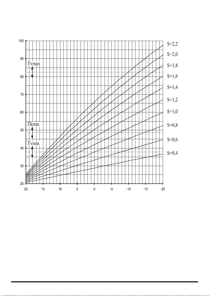
HEAT CURVE DIAGRAM
Tv (°C)
Stand pipe temperature
Settings manual
Ta (°C)
Outdoor temperature
20

MENU
You can change the time programs and set the controller with commands and functions, that
you can find in the menu.
ENTERING AND NAVIGATING TROUGH THE MENU
To enter the menu press and hold the navigation button for 2 seconds. You
can browse through the menu by turning the navigation button to the left or to
the right and you can select items by pressing the button. By pressing “ESC”
you can go back one level.
In the continuing of this user manual we will call the “navigation button” as
“button”.
2 s
21
Settings manual

MENU STRUCTURE
The menu is built in five groups, in which the settings, data and other functions are divided
as follows:
TIME PROGRAMS
ROOM HEATING P1
ROOM HEATING P2
D. H. W. WARMING
D. H. W. CIRCULATION
ANTI LEGIONELLA PROGRAM
EXIT
CONTROLLER PARAMETERS
BASIC PARAMETERS
REQUIRED DAY TEMPERATURE
REQUIRED NIGHT TEMPERA
FROST PROTECTION
SOMMER/WINTER SWITCHOVER
EXIT
MIXING HEATING CIRCUIT
HEATING CURVE STEEPNES
EXIT
DIRECT HEATING CIRCUIT
HEATING CURVE STEEPNES
EXIT
DOMESTIC HOT WATER
REQUIRED D. H. W. TEMPERATURE
SUN COLLECTORS DIFFERENCE
EXIT
HEAT SOURCES
MIN. LIQUID BOILER TEMPERATURE
MIN. SOLID BOILER TEMPERATURE
EXIT
BASIC SETTINGS
SET LANGUAGE
SET TIME
EXIT
DEFAULT SETTINGS
TIME PROGRAMS
ALL SETTINGS
USER SETTINGS
SAVE USER SETTINGS
EXIT
CONTROLLER DATA
Settings manual
22

PROGRAM TIMER
A weekly program timer with interactive innovative programming modes is built in the controller. You can choose between five independent time programs.
SELECTING THE PROGRAM
Selecting the program that you want to view or change:
TIME PROGRAMS > ROOM HEATING P1
ROOM HEATING P2
D. H. W HEATING
D. H W. CIRCULATION
ANTI LEGIONELLA PROGRAM
available programs
VIEWING AND CHANGING THE TIME PROGRAM
Programming is interactive with a graphic interface. You can browse through the data (icons)
on display with the navigation button.
The first icon on the display represents the day of the week, you
can change the selected day. Press the button, now the “DAY”
symbol starts to flash and you can select another day with turning
the button. Confirm the selection by pressing the button. The program for the selected day is shown on the timeline.
The second icon is used for copying the time program from the
selected day to the next day. Press the button to select the item
and confirm the selection by pressing it again. When copying is
finished, the next day is automatically selected.
23
Settings manual

The last and most important item on
the display is the timeline with a
graphical display of a time program for
a selected day. Dark fields represent
heating intervals of the day temperature, the rest is heating to the night
temperature.
Use the button to move the cursor
(flashing line) along the timeline.
A time reading, representing the cursor’s position on the timeline is displayed o n the scr een . W hen the curs or
reaches daytime temperature interval,
the display shows a time of the beginning and end of the interval or operation.
Changing the
heating intervals
Adding new
heating intervals
Deleting intervals
To change the beginning or end of the
time interval, move the cursor inside
the interval. Now press the button and
the cursor will be placed to the beginning of the interval, from where you
can move it a long th e timeli ne with t he
button. When you find the preferred
time of the beginning of the time interval, confirm it by pressing the button.
Now the cursor will be placed to the
end of the interval, from where you can
again move it to the left or to the right
and confirm the position by pressing
the button.
You can add a new interval by placing a cursor at the preferred
beginning of the interval and pressing a button. Now use the button to find the end of the interval and press it again. A new daytime temperature time interval has been created.
On a timeline for a selected day, you can set only three
day temperature intervals.
To erase an interval, select it and press the button, then drag the
beginning of the interval all the way to its end and press the button
again. The interval has been erased.
Settings manual
24
FACTORY SET TIME PROGRAMS
Program for
room heating
Program for
room heating
Program for
d. h. w. heating
Program for
d. h. w. circulation
Day Heating active
MON – FRI 05:00 - 07:30
13:30 - 22:00
SAT - SUN 07:00 - 22:00
Day Heating active
MON – FRI 06:00 - 22:00
SAT - SUN 07:00 – 23:00
Day Heating active
MON – FRI 06:00 - 22:00
SAT - SUN 07:00 – 23:00
Day D. h. w. circulation active
MON – FRI 05:30 - 7:30
15:00 - 22:00
SAT - SUN 06:30 - 8:30
12:00 - 14:00
16:00 - 23:00
Program for protection
against legionella
If the room unit DD2 is connected then the time program for room heating, is
used from the DD2 (factory setting).. For the d. h .w. warming however, the time
program from the controller is used. This setting can be changed with parameter P1.10 on the room unit for room heating and with parameter S4.12 on the
controller for d. h. w. warming.
Day Program active
FRI 5:00 – 6:00
25
Settings manual
CONTROLLER PARAMETER SETTINGS
CONTROLLER PARAMETERS
In the group »CONTROLLER PARAMETERS« , the parameters are divided into five groups:
CONTROLLER PARAMETERS >
> MIXING HEATING CIRCUIT
> DIRECT HEATING CIRCUIT
> DOMESTIC HOT WATER
> HEAT SOURCES
BASIC PARAMETERS
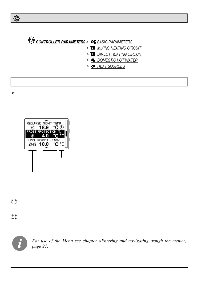
RULES FOR PARAMETER SETTINGS AND OVERVIEW
Select the parameter you want to change with the button. In the first row is a brief parameter
descpriction, in the second row there is a graphical symbol, parameter value and an icon for
setting the parameter (analogue or digital).
a brief description of the parameter
parameter setting option
setted parameter value
graphic symbol
Parameter changing option are:
Setting is made with buttons on the controller.
Setting is made with the navigation button.
By pressing the button, the value of the parameter begins to flash, now you can alter
the value and confirm it by pressing the button again.
For use of the Menu see chapter »Entering and navigating trough the menu«,
page 21.
Settings manual
26

BASIC PARAMETERS
SETTING THE REQUIRED DAY TEMPERATURE
The required day temperature can be viewed, by choosing:
CONTROLLER PARAMETERS > BASIC PARAMETERS >
SETTING THE REQUIRED NIGHT TEMPERATURE
The required night temperature can be viewed, by choosing:
CONTROLLER PARAMETERS > BASIC PARAMETERS >
FROST PROTECTION SETTING
When the h eating is turned off or it is not necess ary, the controll er turns off the bo iler. By
existing danger of freezing the boiler is automaticaly turned on, if the outdoor temperature
drops bellow the setted frost protection temperature. Default setting is 2 °C and can be set in
span between –20 and 10 °C.
Frost protection can be set by choosing:
REQUIRED DAY TEMPERATURE
REQUIRED NIGHT TEMPERATURE
CONTROLLER PARAMETERS > BASIC PARAMETERS >
SUMMER/WINTER SWITCHOVER TEMPERATURE SETTING
The controller has a built-in function, which automaticaly turns the heating off, if the average
24h temperature is higher than the setted summer/winter switchover temperature. The heating is turned on again, when the average 24 h temperature drops bellow the setted
switchover temperature. If the operation mode switch is in position »day temperature«, than
the described function is deactivated. Default setting is OFF and can be set in span between
10 and 30 °C, OFF.
FROST PROTECTION
Required room temperature is set on 6 °C by default and can be changed in service
parameter S1.11.
27
Settings manual

Summer/winter switchover temperature can be set by choosing:
CONTROLLER PARAMETERS
When an automatic switch to summer heating mode is made, then the symbol is shown
on the display.
MIXING HEATING CIRCUIT
HEATING CURVE STEEPNESS
D10
DIRECT HEATING CIRCUIT
SUMMER/WINTER SWITCHOVER
Heating curve steepness is set with a button on the controller. The setted curve steepness can be viewed by choosing:
D20
CONTROLLER PARAMETERS
MIXING HEATING CIRCUIT >
HEATING CURVE STEEPNESS MC
> BASIC PARAMETERS >
>
HEATING CURVE STEEPNESS
D10 D20
Settings manual
Heating curve steepness is set with a button on the controller. The setted curve steepness can be viewed by choosing:
CONTROLLER PARAMETERS
MIXING HEATING CIRCUIT >
HEATING CURVE STEEPNESS MC
28
>
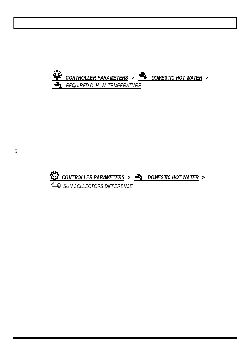
DOMESTIC HOT WATER
D. H. W . REQUIRED TEMPERATURE SETTING
Required d. h. w. temperature can be set, by choosing:
CONTROLLER PARAMETERS > DOMESTIC HOT WATER >
REQUIRED D. H. W. TEMPERATURE
SUN COLLECTORS DIFFERENCE
When the sun collectors temperature exceeds the d. h. w. temperature for the value of
switch-on difference, then the circulat ion pu mp KTP is switched on.
Sun collectors difference is set on 12 °C by default, and can be changed in span from 5 to
30 °C.
Sun collectors difference can be set, by choosing:
CONTROLLER PARAMETERS
SUN COLLECTORS DIFFERENCE
> DOMESTIC HOT WATER >
29
Settings manual
HEAT SOURCES
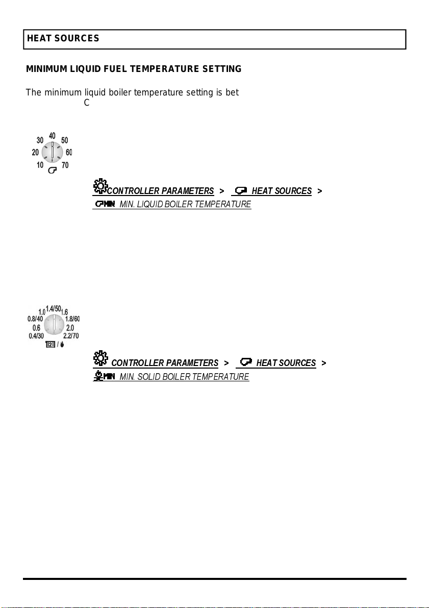
MINIMUM LIQUID FUEL TEMPERATURE SETTING
The minimum liquid boiler temperature setting is between 35 °C and 55 °C. For other boilers
between 50 °C and 70 °C. If the boiler temperature is below the minimum setting, the controller will gradually close the mixing valve..
Minimum liquid boiler temperature is set with a button on the controller. The
setted temperature can be viewed, by choosing:
CONTROLLER PARAMETERS > HEAT SOURCES >
MIN. LIQUID BOILER TEMPERATURE
MINIMUM SOLID FUEL BOILER TEMPERATURE SETTING BY D20
Usually the minimum solid fuel boiler temperature is set between 35 °C and 70°C. If the
boiler temperature is below the minimum setting, the controller will gradually close the mixing
valve and disable the domestic hot water pump.
Minimal solid fuel boiler temperature is set with a button on the controller.
The setted curve steepness can be viewed, by choosing:
CONTROLLER PARAMETERS > HEAT SOURCES >
MIN. SOLID BOILER TEMPERATURE
Settings manual
30

BASIC CONTROLLER SETTINGS
SET LANGUAGE
User interface language is set in the menu by choosing:
BASIC SETTINGS >
Select the desired language and confirm it by pressing the button.
SET LANGUAGE
For use of the Menu see chapter »Entering and navigating trough the menu«,
page 21.
SET TIME
Time and date is set in the menu by choosing:
BASIC SETTINGS >
SET TIME
Move with the button to the item you want to change and
press the button. Selected item begins to flash. Now with
turning the button you can change the value. Setted value is confirmed with by pressing the button. Now you can
select another item to modify and repeat the procedure.
When you are finished or if you want to cancel the time and date settings you can press the
ESC key for return to the previous menu.
For use of the Menu see chapter »Entering and navigating trough the menu«,
page 21.
31
Settings manual

DEFAULT SETTINGS
This part of the menu allows you to reset the controler setings to the default values or save/
load the user settings. You have the following options:
DEFAULT SETTINGS >
returns the default time programs.
> ALL SETTINGS
Returns all the parameters to its default values.
> USER SETTINGS
Loads the previous saved user settings.
which are possibly in an error state (ERR) are reset to status - - -
(sensor not connected).
Before execution any of given commands, the controller requests the confirmation of the
chosen command.
It deletes the setted user programs and
>
>
TIME PROGRAMS
SAVE USER SETTINGS
Saves the current settings to user settings. All temperature sensors,
EXIT
Now choose the desired answer with turning the button
and confirm it with pressing the button.
For use of the Menu see chapter »Entering and navigating trough the menu«,
page 21.
CONTROLLER DATA
This command displays the data of controller type and software version.
Controller type
Software version
For use of the Menu see chapter »Entering and navigating trough the menu«,
page 21.
Settings manual
32
DECLARATIONS AND STATEMENTS
DECLARATION OF CONFORMITY
The manufacturer hereby declares under its sole responsibility that products PROMATIC
D10 and PROMATIC D20, that are covered by this Declaration, comply with the protection
requirements of the Directive on electrical equipment, designed for use within certain voltage
limits (EEC’s Low Voltage Directive 73/23/EEC, 93/68 EEC) and the requirements of the
Directive on electromagnetic compatibility (EEC’s Directive on electromagnetic compatibility
89/336 EEC, 92/31 EEC, 93/68 EEC).
Product description: Weather compensated heating controllers
Name of the product: PROMATIC D10 and PROMATIC D20
Applied standards:
EN 60730-1:1995, EN60730-2-9:1997,
EN 50081-1:1995, EN 50082-1:1995,
EN 55014-1:2001, EN 55014-2:1997,
EN 12098-1:2002.
DISPOSAL OF OLD ELECTRICAL & ELECTRONIC EQUIPMENT
Discarding old electrical and electronic equipment (valid for EU member states and other
European countries with organized separate waste collection).
This symbol on the product or packaging means the product cannot be
treated as a household waste and it has to be disposed of separately via
designated collection facilities for old electrical and electronic equipment
(OEEO). The correct disposal and separate collection of your old appliance
will help prevent potential negative consequences for the environment and
human health. It is a precondition for reuse and recycling of used electrical
and electronic equipment. For more detailed information about disposal of
your old appliance, please contact you city office, waste disposal service or
the shop where you purchased the product.
33
Statements

WARRANTY STATEMENT
This product complies with all the regulations and declared characteristics. We grant 2 years
guarantee on the product, commencing on the date of purchase. We will eliminate any
defects in the product resulting from faults in materials, workmanship, malfunctions or imperfection. We retain the right to repair or completely replace the product as we may choose.
This guarantee does not cover damages as a result of improper use, normal wear and defects that have no effect on value, functionality and operation safety of the product. This
guarantee becomes void if repairs are done by unauthorized person or original spare parts
are not used.
For service within the guarantee period, hand or send the complete product, together with
the sales receipt to authorised service or dealer. This guarantee is valid in every country,
where the product was supplied by the manufacturer or its authorised dealer.
Statements
34

NOTES
35
Notes

Solarbayer GmbH
Solarbayer GmbH
Am Dörrenhof 22
Am Dörrenhof 22
85131Pollenfeld-Preith
85131Pollenfeld-Preith
Deutschland
Deutschland
tel: +49 (0) 84 21 / 9 35 98 - 0
tel: +49 (0) 84 21 / 9 35 98 - 0
fax: +49 (0) 84 21 / 9 35 98 - 29
fax: +49 (0) 84 21 / 9 35 98 - 29
http://www.solarbayer.de
http://www.solarbayer.de
Email: info@solarbayer.de
Email: info@solarbayer.de
We reserve the right to make changes without notice.
Programm v2.0
O3060007 v2.0
01MC060060
 Loading...