


Room unit DD2
User manual
GB
Setting manual
Installation manual

2

Room unit synchronization
After the wiring connection, the DD2 shall be synchronized
with the controller. To synchronize the DD2, hold the key for
30 seconds. Release the key after two successive beeps . The
DD2 synchronization is now in progress. After another beep, the
DD2 is synchronized and the work can continue.
DD2 shall be synchronized with the controller only after
all the temperature sensors have been connected.
The signal cable length between the DD2 and the controller must not exceed 50 metres.
3

Table of contents
Room unit synchronization .................................................................... 3
User manual
DD2 description ..................................................................................... 6
Operating mode selection ...................................................................... 7
Setting the day and night temperatures ................................................. 7
Setting the comfort temperature ............................................................ 8
PARTY and ECO operating modes ........................................................ 9
Holiday mode ........................................................................................ 9
Setting the accurate time ....................................................................... 10
Program timer ........................................................................................ 11
Preset time programs ............................................................................ 15
Remote co n tr o l ...................................................................................... 15
Room unit locking .................................................................................. 15
One-time manual d. h. w. warming activation ......................................... 15
Indi cation o f controlle d devices on the d isplay ........................................ 15
Quick save and exit command (Escape) ................................................ 16
Battery insertion and replacement ......................................................... 16
Setting manual
Menu ..................................................................................................... 17
Factory default settings - DD2 reset ....................................................... 25
Installation manual
Mounting location .................................................................................. 26
Wall plate mounting ............................................................................... 26
Wiring connections ................................................................................ 27
Active an passive room unit operating mode .......................................... 30
Behaviour with solid fuels ...................................................................... 30
Adaptive algorhythm .............................................................................. 30
Coding switch ........................................................................................ 31
DD2 troubleshooting .............................................................................. 32
Technical data ....................................................................................... 35
Conformity with standards and directives ............................................... 35
Guara ntee ............................................................................................. 36
Disposal of Old Electr ical & Electronic Equ i pment ................................ 37
Notes ..................................................................................................... 38
4

DD2 description
The DD2 room unit is a modern designed and efficient device for
remote central heating control. It has the following features:
- selection of preset programs for room heating and domestic
hot water warming,
- operating mode selection,
- desired room temperature setting, and
- customer time programs for room heating and d. h. w. warming.
All measured temperatures and settings can be viewed on the
LCD display and modified. With the Party and Eco keys, the day
or economic temperature mode can be selected. The DD2 room
unit also enables the connection of an auxiliary temperature sensor as well as remote activation via telephone.
LEGEND
Hold key while pressing other keys.
Hold key until a beep sound is heard.
Press and release key.
Press key to increase or decrease value.
USER MANUAL
5

Controlled devices
-
gas boiler
-
liquid fuel
boiler
- solid fuel
boiler
- mixing valve
- pump
- d. h. w. storage
tank
- heat acc u mulator
- direct circuit
- solar collectors
- d. h. w. circulation
Actual
temperature
Empty batteries
Day and night
Remote activation
Frost protection
Keyboard
locking
PARTY
Knob for day
temperature
setting
Program timer CH2
- d. h. w. warming
ON
- active
OFF
- inactive
Program timer CH1
- day temperature
- night emperature
ECO
Operation accord-
ing to the progr am
timer
Operation mo de
- off
- room heating
- d. h. w.
warming
PARTY
temperature m od e
- day
Stand by
mode
Figure 1
6
Night t
temperatur e
setting
On mode
-
operation
according to the
program timer
ECO
- saving
temperature
mode
USER MANUAL
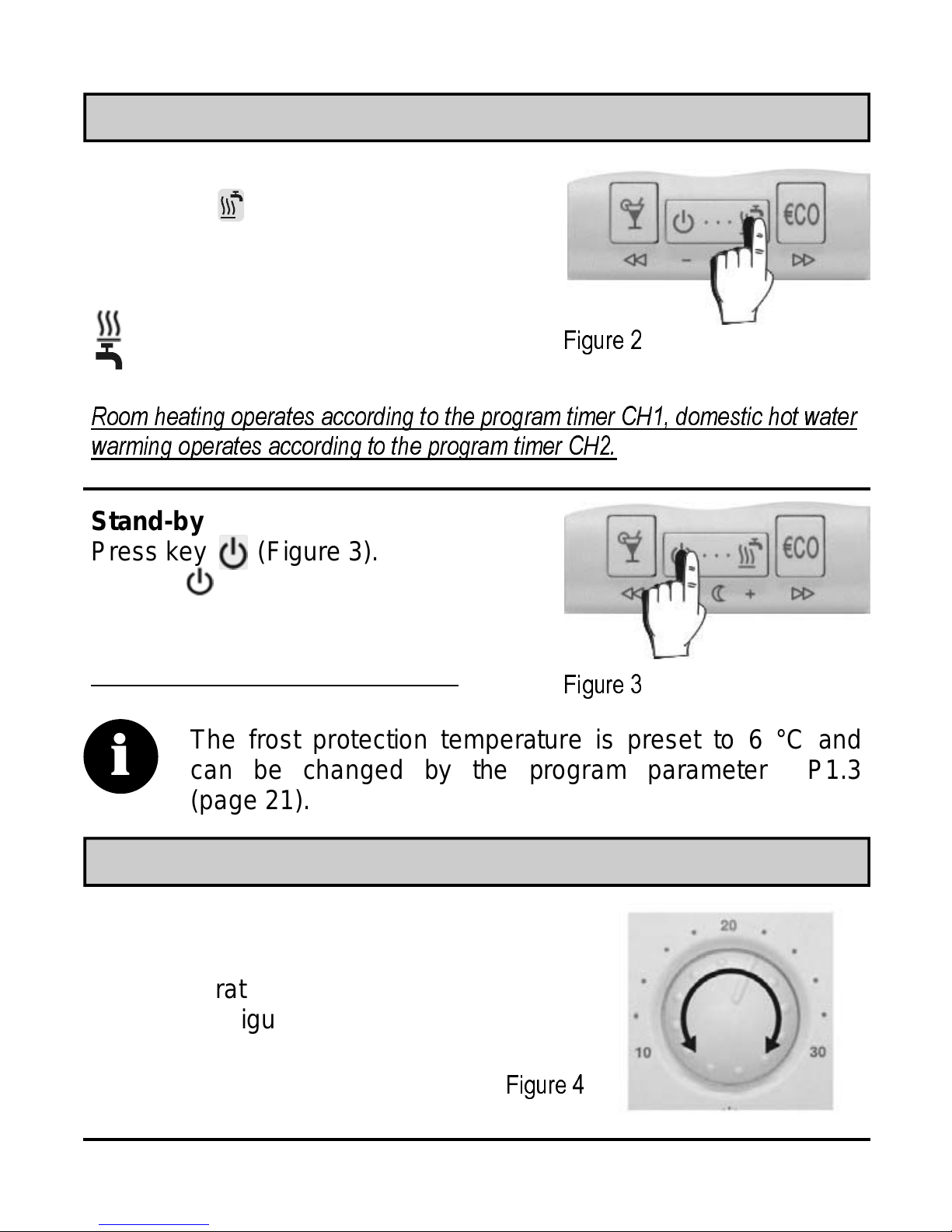
Operating mode selection
Heating activation
Press key to select the desired
operating mode (Figure 2). The
selected operation mode appears
on the display.
- room heating
- domestic hot water warming
Room heating operates according to the program timer CH1, domestic hot water
warming operates according to the program timer CH2.
Stand-by
Press key (Figure 3). The
Symbol appears on the display.
Frost protection remains act iv e.
The frost protection temperature is preset to 6 °C and
i
can be changed by the program parameter P1.3
Figure 2
Figure 3
(page 21).
Setting the day and night temperature
Day temperature
Turn the knob to set the desired
day temperature between 10 °C
and 30 °C (Figure 4).
USER MANUAL
Figure 4
7

Night temperature
Hold key ( ) for approx. 5 seconds (Figure 5a). Release
key after a beep. Now press key ( ) or ( ) to set the desired night temperature (Figure 5b). To save and quit set-up,
press key ( ) once more.
Figure 5a
Figure 5b
Setting the comfort temperature
Hold key for 5 approx. seconds (Figure 6a). Use key ( ) or
( ) to set the COMFORT temperature between 10 °C and
30 °C (Figure 6b). To save and quit set-up, press key once
more or don’t touch any key for a while.
Figure 6a
Room heating with the comfort temp. operates according to program timer CH3
Figure 6b
and has priority over the room heating according to the program timer CH1.
If the comfort heating mode is inactive, the setting of comfort
i
8
temperature is also inactive. The co mfor t t e mperatur e m o d e is
set by t h e p r o gr a m pa r am e te r P1.5 (page 21).
USER MANUAL

PARTY and ECO operating modes
PARTY - day temperature operation
Press key . Use key ( ) or ( ) to set duration of the
PARTY mode between 1 and 24 hours. For permanent PARTY
mode, select on.
To stop PARTY mode at any time, press key .
ECO - night temperature operation
Press key . Use key ( ) or ( ) to set duration of the
ECO mode between 1 and 24 hours. For permanent ECO mode,
select on.
To stop ECO mode at any time, press key .
The ECO temperature reduction is set by the program parameter P1.2
i
(page 21).
Holiday mode
Hold key for approximately 15 seconds. Release the key after
a beep. Use key ( ) or ( ) to set the duration of the HOLIDAY mode between 1 and 99 days.
To stop the HOLIDAY mode at anytime, hold the key for 15
seconds again.
The HOLIDAY m ode temp eratur e i s set by the pr ogram pa-
i
USER MANUAL
rameter P1.4 (p age 21 ). The fac tory prese t HOLIDAY temper ature is 12 °C.
9

Setting the accurate time
Hours
Hold key and press key ( )
or ( ) to set the hours
(Figure 7).
Minutes
Hold key and press key
( ) or ( ) to set the
minutes (Figure 8).
Figure 7
Day
Hold both keys and , then
press key ( ) or ( ) to set
the day (Figure 9). The days are
marked from 1 to 7. Monday is
marked as 1 and Sunday as 7.
If the battery is reinserted after the DD2 hasn’t been
i
operating for a while, the time is set to Monday, 20:00.
Figure 8
Figure 9
10
USER MANUAL

Program timer programming
The program timer has three channels: CH1, C H2 and CH 3.
CH1 is used for programming the room heating (day / night),
CH2 is used for programming the domestic hot w ater warming,
CH3 is used for programming the comfort room heating.
Selecting the program channel
Hold key and press key (Figure 10). Release both keys
after beep. Press key ( ) or key ( ) to select the program channel that has to be modified.
Figure 10
Modifying the time program
Press key ( ) or ( ) to select the program place that has to
be modified. The time command, the successive number of the
program place (Figure 11) and the switch-on/off command
(Figures 12, 13 and 14) are shown in the display simultaneously.
Time
command
Figure 11
USER MANUAL
Successive number
of the program place
11

CH1
- day temperature
Figure 12
- night temperature
CH2
- domestic hot
water warming active
- domestic hot
Figure 13
water warming inactive
CH3
- comfort temperature
Figure 14
active
- comfort temperature
inactive
Now press key ( ). The day starts to flash on the display.
Press key ( ) or ( ) to set the day, then press key ( ).
Hours start to flash on the display. Press key ( ) or ( ) to
set the hours, then press key ( ). Minutes start to flash on
the display. Press key ( ) or ( ) to set minutes, then press
key ( ). The display stops flashing. It is possible to move to
the next program place now. Press ( ) to move to the next program place or press ( ) to move to the previous program place.
Every channel in the program timer (CH1, CH2 and CH3) has 32
program places. Time commands for day and night temperature
mode, time commands for active and inactive d. h. w. warming and
time commands for active and inactive comfort temp. mode are
displayed su ces si vel y.
12
USER MANUAL

Unused time commands are indicated as
- -:- -
(Figure 15). For a better clear-
ness, the DD2 does not display all unused program spaces.
Unused time
command
Figure 15
Preset time programs
The DD2 room unit has 4 preset time programs for room heating
and 4 preset time programs for domestic hot water warming.
Preset time program selection
Hold key and select the suitable time program by pressing the
key (Figure 16). The symbol indicates programs for room
heating (CH1), while the symbol indicates programs for domestic hot water warming. (CH2). To view the time commands in a program, press key ( ) or ( ).
The selected time program always cancels the previous one.
Select - - - to keep the current time program active.
Figure 16
USER MANUAL
13
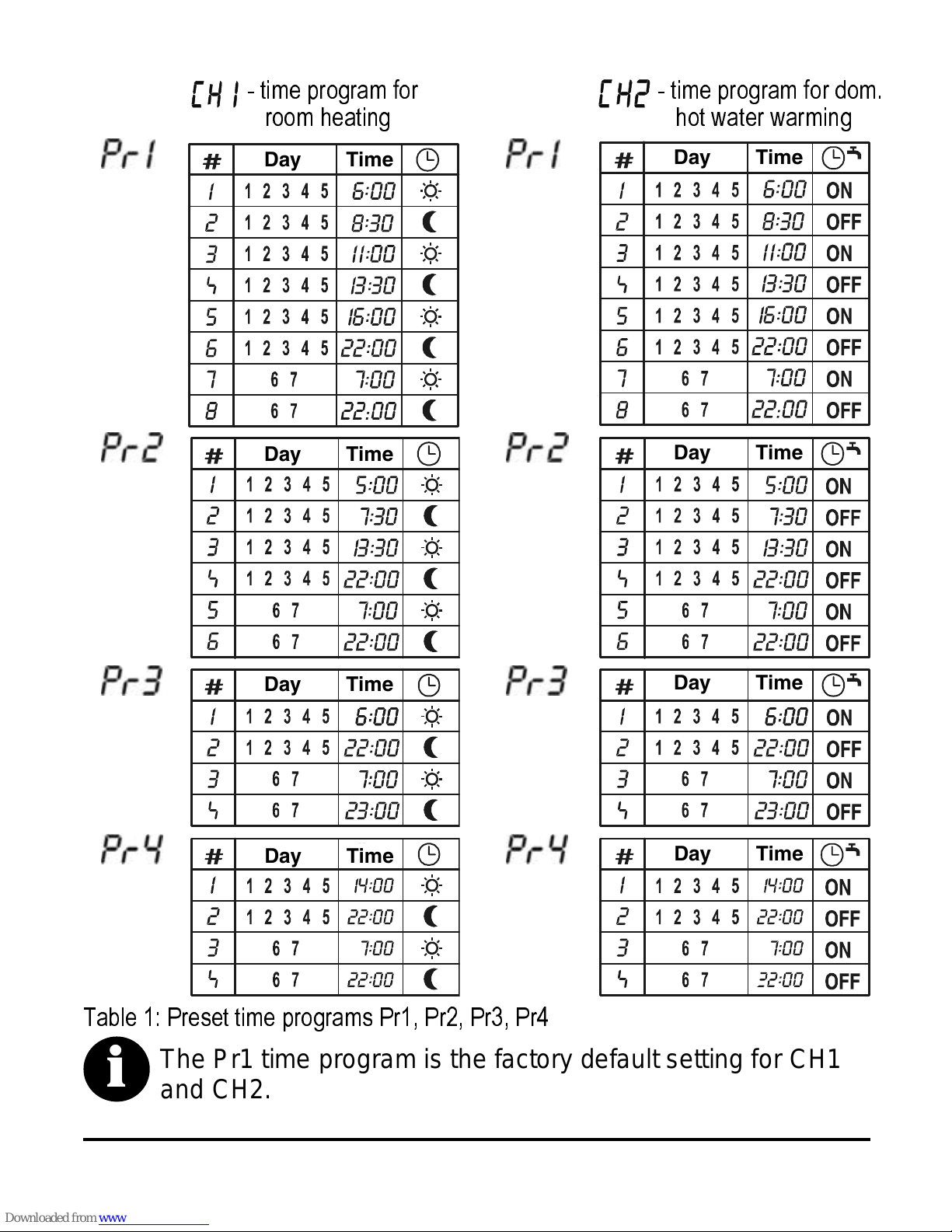
- time program for
- time program for dom.
room heating
Day Time
Day Time
hot water warming
Day Time
Day Time
Day Time
Day Time
Table 1: Preset time programs Pr1, Pr2, Pr3, Pr4
The Pr1 time program is the factory default setting for CH1
i
14
and CH2.
Day Time
Day Time
USER MANUAL

Remote control
The day temperature operating mode can be activated remotely
via telephone. This function is described in the chapter Program
group P3 (page 22).
One-time manual d. h. w. warming activation
Hold the key for 5 seconds. Release the key after a beep.
The one-time manual domestic hot water warming is
i
automatically deactivated as soon as the desired d. h. w.
temperature is reached or, at the latest, after 1 hour.
Room unit locking
Hold the key for 15 seconds. Release the key after a beep. The
symbol indicates a locked room unit. To unlock the DD2, hold
the key for 15 seconds.
Setting or modifying the parameters by locked DD2 isn’t possible or
is limited.
DD2 locking is set by the service parameter S1.8
i
(page 23).
Indication of controlled devices on the display
If the indication of controlled devices is deactivated (setting by program parameter P1.11), the currently controlled devices can be
viewed by holding the key and pressing the key (Escape).
All the controlled devices will appear on the display for 15 seconds.
USER MANUAL
15
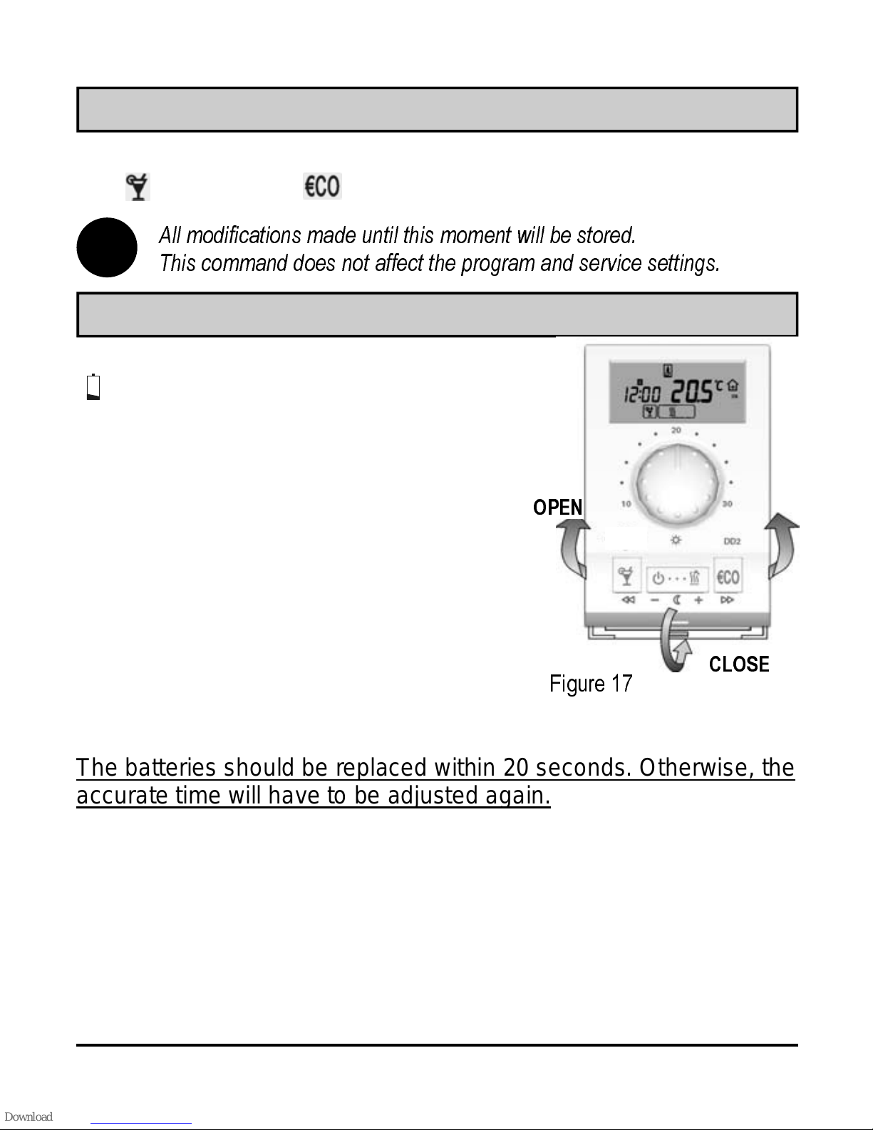
Command to quick save and quit (Escape)
Every time when the set-up mode has to be quit quickly, hold the
key and press the key. Release both keys after a beep.
All modifications made until this moment will be stored.
i
This command does not affect the program and service settings.
Battery replacement
Low batteries are indicated by the
symbol on the display. The batteries
should be replaced every 2 years. The
DD2 uses two 1.5 V type AAA alkaline
batteries as its power supply. The battery
socket is inside the ST1. To remove the
room unit from the wall plate, the room
unit shall be gripped in the height of the
keys and pulled off the wall plate (Figure
17 - OPEN). After the battery replacement, put the DD2 back to the wall plate
by sticking it on top and pushing it with
its bottom towards the wall plate (Figure
17 - CLOSE).
The batteries should be replaced within 20 seconds. Otherwise, the
accurate time will have to be adjusted again.
OPEN
CLOSE
Figure 17
16
USER MANUAL

Menu
All data and settings are divided into 16 groups:
CH1 ·············· program timer for room heating
CH2 ·············· program timer for d. h. w. warming
CH3 ·············· program timer for comfort room heating
t1 ·················· measured temperatures
t2 ·················· preset and controller-calculated temperatures
t3 ·················· controlle r settings
t4 ·················· room temperature during the last heating interval
d1 ················· room unit data
d2 ················· controller data
P1 ················· program settings
P2 ················· heating curve slope
P3 ················· remote activation via telephone
P4 ················· overview of controllers in the BUS network
S1 ················· service group 1
S2 ················· service group 2
S3 ················· service group 3
Menu
To enter the menu, hold key and press key (Figure 18).
Release both keys after a beep. The first group CH1 appears on
the display.
Figure 18
Menu navigation
In the menu, the keys get a new significance marked below them
(Figure 19). To move between the groups, press the ( ) key
to move to the left and the ( ) key to move to the right
(Figure 20). To move
USER MANUAL
17

within a particular group, press the ( ) key to move downwards and the ( ) key to move upwards. For an easier understanding and navigation, all the lines are designated. The first two
symbols stand for the group, while the third one indicates the successive number of the line within the group (Figure 21).
Figure 19
Enter
Move to
the left
Move down or
decrease
Move to
the right
Move up or
increase
The S groups are locked by factory default settings.
Figure 20
For unlocking the S groups, see chapter Service group S3 (page 24).
i
Successive No.
of the line
Figure 21
18
Group
name
Parameter
SETTING MANUAL

Program timer for room heating CH1
For changing the time program see chapter Modifying the time
program (page 11).
Program timer for domestic hot water warming CH2
For changing the time program see chapter Modifying the time
program (page 11).
Program timer for comfort room heating CH3
For changing the time program see chapter Modifying the time
program (page 11).
Measured temperatures t1
This group is intended for the overview of all measured temperatures. The temperatures are displayed in the following order:
- [t1.1] outside temperature AF
- [t1.2] room temperature RF
- [t1.3] stand-pipe temperature VF
- [t1.4] return-pipe temperature RLF
- [t1.5] boiler temperature KF
- [t1.6] boiler return-pipe temperature RLKF
- [t1.7] d. h. w. temperature BF1
- [t1.8] d. .h. w.
temperature BF2 or solid fuel boiler temp. KF2
- [t1.9] solar collectors temperature KTF
- [t1.10] auxiliary room sensor temperature RF2
- [t1.11] floor temperature EF
Set and controller-calculated temperatures t2
This group is intended for the overview of all set and controllercalculated temperatures. The temperatures are displayed in the
following order:
- [t2.1] average (current) outdoor temperature
- [t2.2] desired room temperature
- [t2.3] calculated stand-pipe temperature - indirect circuit
- [t2.4] calculated stand-pipe temperature - direct circuit
- [t2.5] calculated boiler temperature
- [t2.6] desired d. h. w. temperature
- [t2.7] calculated solid-fuel boiler temperature
SETTING MANUAL
19

Controller settings t3
This group is intended for the overview of all controller settings.
The settings are displayed in the following order:
- [t3.1] minimum boiler temperature
- [t3.2] heat curve slope - indirect circuit
- [t3.3] heat curve slope - direct circuit or
[solid fuel boiler temperature] or
[temperature difference for solar collectors]
- [t3.4] desired d. h. w. temperature
- [t3.5] desired day temperature
- [t3.6] desired night temperature
- [t3.7] coding switch position
- [t3.8]
minimum or maximum stand-pipe temperature limitation
- [t3.9] coding switch setting
- [t3.10] battery condition on controller
Room temperature during the last heating interval t4
This group is intended for the overview of room temperatures during the last heating interval. The temperatures are displayed in the
following order:
- [t4.1] minimum room temperature during the last heating interval
- [t4.2] maximum room temperature during the last heating interval
- [t4.3] average (current) room temperature deviation
Room unit data d1
This group is a sort of DD2 ID. In contains information about the
DD2. The information are displayed in the following order:
- [d1.1] room unit type (DD2)
- [d1.2] software version
- [d1.3] heating or cooling
- [d1.4] built-in temperature sensor calibration
- [d1.5] battery voltage
20
SETTING MANUAL
Controller data d2
This group is a sort of controller ID. The information are displayed
in the following order:
- [d2.1] controller type
(31 - PROMATIC D10, 41 - PROMATIC D20)
- [d2.2] controller software version
Program group P1
Program group P1 is used for the room unit user settings. To
change the selected parameter, hold the key for approximately 5 seconds. Parameter starts to flash. Press key ( ) or
( ) to set the parameter value. To store the set value, hold
the key for approximately 5 seconds again. The P1 group
contains the following parameters; (factory default setting):
- [P1.1] night temperature (6 °C ÷ 26 °C); (17 ° C)
- [P1.2] temperature reduction in ECO mode (0 °C ÷ -9 °C); (-3 K)
- [P1.3] frost protection temperature (0 °C ÷ 20 °C); (6 ° C)
- [P1.4] holiday mode temperature (5 °C ÷ 25 °C); (12 ° C)
- [P1.5] comfort mode temperature
(10 °C ÷ 30 °C, - - - inactive); (- - -)
- [P1.6] d. h. w. temperature (the parameter is not in use
)
- [P1.7] temperature sensor calibration (-2 °C ÷ 2 °C); (0 K)
- [P1.8] display of measured temperatures (1 - room, 2 - outdoor,
3 - room and outdoor alternating, 4 - requested temp.); (1)
- [P1.9] beeper mode
(- - - silent, 1 - at typing, 2 - at timer switchover,
3 - at typing and timer switchover); (1)
- [P1.10] program timer selection
(1 - timer on controller, 2 - timer on DD2); (1)
- [P1.11] display of controlled devices (1 - visible, - - - – hidden); (1)
SETTING MANUAL
21

Program group P2
Program group P2 is intended for setting the heat curve slope. To
change the selected parameter, see Program group P1 (page 21)
The P2 group contains the following parameters;
(factory default setting):
- [P2.1] heat curve slope correction (-0.5 ÷ 0.5); (0)
- [P2.2] parallel heat curve shift (-10 K ÷ 10 K); (0 K)
Program group P3
Program group P3 is intended for the settings in case of a remote
activation via telephone. To change the selected parameter see
Program group P1 (page 21). The P3 group contains the following
parameters:
- [P3.1] requested room temperature
(P - day temperature set by the knob on controller )
- [P3.1] operating mode (1 - room heating)
Program group P4
This group is intended for the overview of all BUS connected controllers. The information are displayed in the following order:
- [P4.1] master controller (- - -, 31, 41)
- [P4.2] slave controller 1 (- - -, 31, 41
- [P4.3] slave controller 2 (- - -, 31, 41)
Controller code:
- - - no controller connected
31 - PROMATIC D10
41 - PROMATIC D20
22
SETTING MANUAL

Service group S1
Service group S1 is intended for DD2 service settings. To change
the selected parameter see Program group P1 (page 1).
The S1 group contains the following parameters;
(factory default setting):
- [S1.1] measured temperatures roundup
(0.1 K, 0.2 K, 0.5 K, 1.0 K); (0.5 K)
- [S1.2] auxiliary temperature sensor correction (-2 K ÷ 2 K); (0 K)
- [S1.3] room temperature
(- - - no sensor, 1 - built-in sensor, 2 - auxiliary sensor,
3 - avg. of built-in and auxiliary sensor); (1)
- [S1.4] outdoor temperature display - correction (-2 K ÷ 2 K); (0 K)
- [S1.5] menu auto-exit (1 - 20 s, 2 - 200 s); (1)
- [S1.6] Party operating mode (1 - room heating,
2 - domestic hot water warming, 3 - both); (3)
1
- [S1.7] heating optimisat ion
(- - - deactivated, 1 - activated); (- - -)
- [S1.8] room unit locking
(- - - no locking, 1 - no lo cking, l imited key f unction,
2 - Party key and knob e nabled, 3 - on ly Party key enab led,
4 - com plete locking , 5 - room temp erature se nsor infl uence
is disable d for at lea st 5 hours ); (2)
1
Heating optimiza tion: DD2 aut omatical ly calcu lates the switc h-on time s o that the requested
temperature is already reached at the set time (night/day changeover).
SETTING MANUAL
23

Service group S2
Service group S2 is intended for DD2 service settings. To change
the selected parameter see Program group P1 (page 21). The S2
group contains the following parameters; (factory default set-
ting):
- [S2.1] max. day temperature setting scale value
(10 °C ÷ 40 °C); (30 °C)
- [S2.2] min. day temperature setti ng scale value
(0 °C ÷ 40 °C); (10 °C)
- [S2.3] max. day temperature setting - limitation
(10 °C ÷ 40 °C); (- - -)
- [S2.4] min. day temperature setti ng - limitation (0 °C ÷ 40 °C); (- - -)
- [S2.5] knob on room unit (the parameter is not i n use
- [S2.6] communication speed with t he controll er
(1 - slow, 2 - fast); (2)
- [S2.7] timer accuracy correction (-5 sec/day ÷ 5 sec/day); (0 s/day)
Service group S3
Service group S3 is intended for DD2 service settings. To change
the selected parameter see Program group P1 (page 21). The S3
group contains the following parameters; (factory default set-
ting):
- [S3.1] group locking (- - - no locking, 1 - S group s ar e lo c k e d,
2 - S and P groups are locked,
3 - complete menu locked); (2)
)
Access to the S3.1 parameter is possible in the following way:
i
24
hold the key for 20 seconds (Figure 22). Release the key
after a beep. The S3.1 para meter appears on the display. Now
this or any other parameter can be modified.
SETTING MANUAL
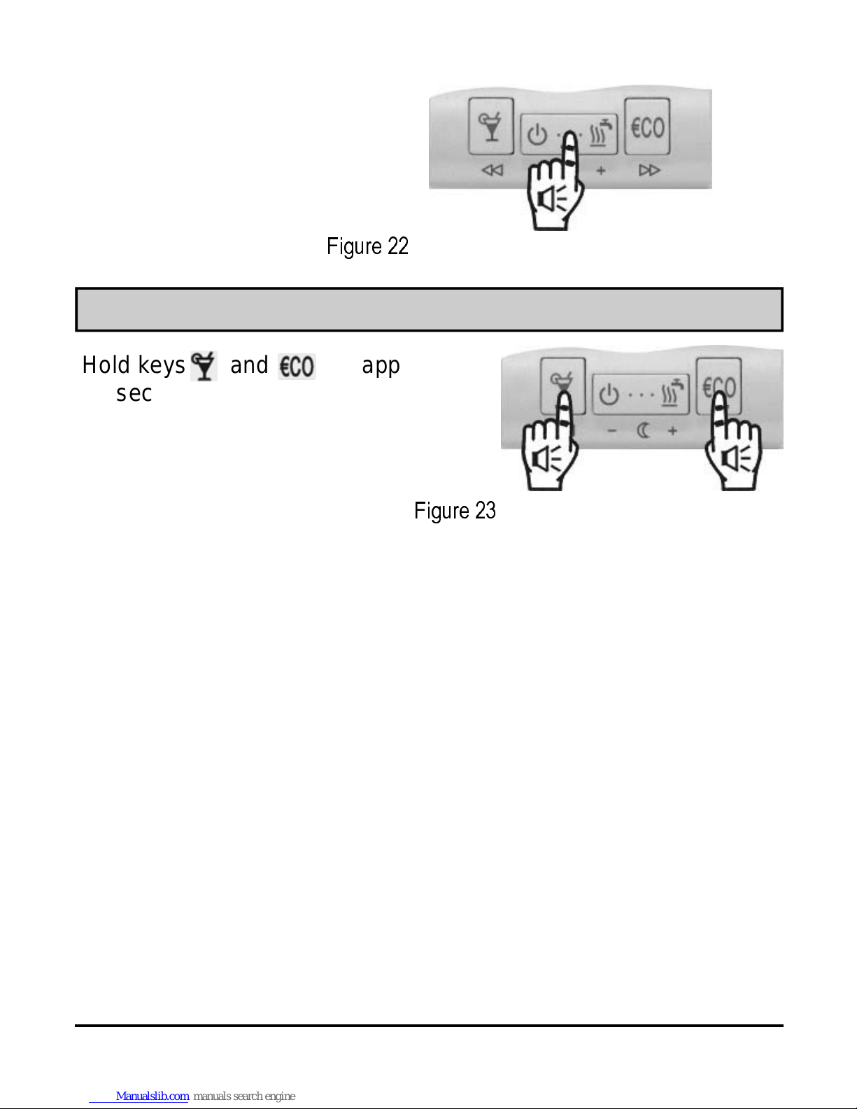
Figure 22
Factory default settings - DD2 reset
Hold keys and for approx.
20 seconds (Figure 23) to restore
the factory default settings. Release the keys after a beep.
Figure 23
SETTING MANUAL
25

Mounting location
The choice of the mounting location is essential for a proper DD2
operation. Suitable locations are inner walls which aren’t exposed
to direct sunlight, local heat sources and draught. The mounting
height should be approximately 150 cm above the floor (Figure 24).
Figure 24
Wall plate mounting
Remove the DD2 from the
wall plate by the following
procedure: hold the DD2 in
the height of keys with one
hand and the wall plate with
the other. Now pull both
parts apart (Figure 25).
Figure 25
26
INSTALLATION MANUAL

The DD2 room unit is intended for wall mounting. In case that no
connection box is installed, use the drilling template and mark drilling holes. Use enclosed screws to fasten the wall plate on the wall
(Figure 26). After the wires have been connected (see chapters
Wiring connections and Connecting the DD2 to a heating control-
ler), put DD2 back onto its base by sticking it on top of the wall
plate and pushing it with its bottom towards the wall plate (cf. Figure 17- CLOSE).
connection
box
wall
Figure 26
INSTALLATION MANUAL
27

Wiring connections
WARNING: Mounting and wiring connections must be carried out
by a skilled heating engineer or an authorized company. Local
regulations or VDE 0100 and EN IEC 60364 regulations for electrical installations must be considered when the wiring connections
are carried out.
Bring the wires through the opening in the wall plate bottom (Figure
26- position A). Connect the terminals 1 and 2 on the room unit with
the controller terminals GND and COM (Figure 28). Use signal cables IY(St)Y 2×0,6 or LiCy 2×0,5 for connection.
After the wires have been connected, put the DD2 back on the wall
plate. A rectangular frame appears on the display (Figure 27). If
the rectangular frame doesn't appear on the display, the
communication between the room unit and the controller hasn't
been established. For troubleshooting refer to the chapter DD2
troubleshooting, page 32).
Figure 27
28
INSTALLATION MANUAL

Connecting the DD2 to a heating controller
DD2 room unit
Figure 28
INSTALLATION MANUAL
PROMATIC controller
29

Behaviour with solid fuels
The DD2 signalizes by means of a beep that the solid fuel has
burned down—applies only for schemes 408 through 413 (S3 =
OFF, S7 = ON). The sound signal only functions when the day
heating mode is on ad the heating is active.
Necess ary DD2 setting:
- the beeper must not be turned off (P1.9 = - - -)
Adaptive algorhythm
The adaptive algorhythm automatically adapts the controller to the
controlled object by correcting the heat curve slope and a parallel
heat curve shift. The adaptation is carried out in accordance with
the average room temperature deviation and other data.
30
INSTALLATION MANUAL
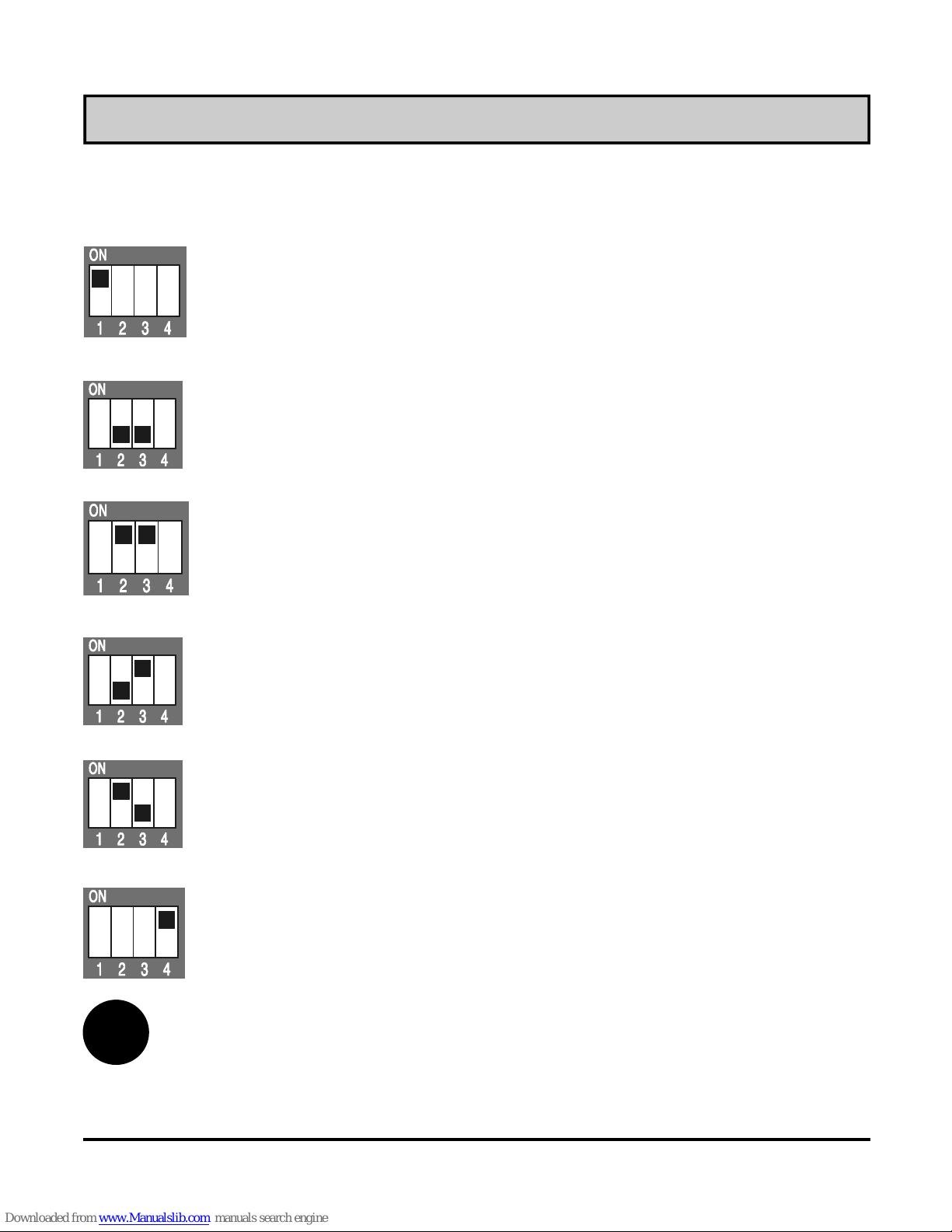
Coding switch
There is a 4-pole coding switch on the DD2 backside. The
meaning of the switches in par ticu lar is:
Adaptive algorhythm activation .
For reference see the chapter Adaptive algorithm
(page 29).
DD2 influences the direct heating circuit.
DD2 influences the indirect heating circuit.
PROMATIC influences the direct heating circuit.
PROMATIC influences the indirect heating circuit.
i
DD2 influences the direct heating circuit.
PROMATIC influences the indirect heating circuit.
PROMATIC influences the direct heating circuit.
DD2 influences the indirect heating circuit.
DD2 works like a terminal, data is read only and can
not be changed.
The adaptation is only taken into account for heating circuits
affected by the DD2 room unit.
INSTALLATION MANUAL
31

DD2 troubleshooting
The room unit automatically detects eventual malfunctions during
operation and displays them on the display. These errors are:
Er1, Er2, Er3 and Er4.
- temperature sensor defect
If appears on the display (Figure 30), it means that the builtin temperature sensor is defective. Send the room unit to the
nearest authorised service or dealer.
Figure 30
- defect of one or more sensors connected to
the controller
If appears on the display (Figure 31), it means that one or
more temperature sensors connected to the heating controller are
defective. Check the resistance and connection of the sensors to
eliminate the defect.
DD2 signalizes error also when the DD2 isn’t syn-
i
chronised with the controller (refer to the chapter Room unit
synchronisation on page 3).
32
INSTALLATION MANUAL

Figure 31
- defect in communication link with the controller
If appears on the display (Figure 32), the communication link
between room unit and controller hasn’t been established at all or
hasn’t been established properly.
Possible causes are:
- connection between the room unit and the controller is
interrupted. The rectangular frame does not appear on the
display (Figure 33). Check the connection between the room
unit and the controller.
- inappropriate communication speed between the room unit and
the controller. To eliminate this malfunction, set the parameter 6
in service group S2 (page 24) to the appropriate value 1.
Figure 32
INSTALLATION MANUAL
Figure 33
33

- defect of the auxiliary temperature sensor
connected to the room unit
When appears on the display (Figure 34), the auxiliary
(external) temperature sensor is defective or hasn’t been
connected. Check the sensor connection and resistance.
Figure 34
34
INSTALLATION MANUAL

Technical data
Model: ............................................. DD2
Power supply: ................................. 8 V DC; max 20 V DC and
2 LR03 size AAA batteries
Temperature sensor: ...................... Murata NTC
Protection degree: .......................... IP 30 acc. to EN 60529
Protection clas s: ............................. II acc. to EN 60730-1
Housing: ......................................... ABS thermoplastic, white
Dimensions (l × w × h): ................... 72 × 32 × 112 [mm]
Weight: ........................................... 150 g
Conformity with standards and directives
The manufacturer declares, under full responsibility, that the DD2
room unit meets the requirements and rules for the electrical
equipment designed for use within certain voltage limits (EC Low
Voltage Directive (LVD) 73/23 EEC, 93/68 EEC) as well as the
requirements and rules for electromagnetic compatibility (EMC)
(EC Directive For Electromagnetic Compatibility 89/336 EEC,
92/31 EEC, 93/68 EEC).
Product description: R oom unit for weather compensated controller
Model: DD2
Applied standards:
EN 60730-1:1995, EN60730-2-9:1997,
EN 50081-1:1995, EN 50082-1:1995,
EN 55014-1:2001, EN 55014-2:1997.
SPECIFICATIONS, DECLARATIONS
35

Guarantee
This product complies with all the regulations and declared characteristics. We grant a 2 years' guarantee on the product, commencing on the date of purchase. We will eliminate any defects in
the product, resulting from defects in material or manufacture,
malfunctions or imperfections. We retain the right to repair or
completely replace the product, as per our own decision.
This guarantee does not cover damages as a result of normal
wear nor defects due to improper handling, installation and use of
the product as well as defects having no influence on its
functionality and operation safety. This guarantee becomes void if
repairs are made by unauthorized persons or unoriginal spare
parts are used.
For the service within the guarantee period, hand or send the
complete product, together with the sales receipt, to the authorised service or dealer. The guarantee is valid in each country
where this product is sold by SOLARBAYER itself or by its authorized dealer.
36
GUARANTEE

Disposal of Old Electrical & Electronic
Equipment
Disposal of Old Electrical & Electronic Equipment (to apply in
countries belonging to the European Union and other European
countries with a special recycling system for these devices).
This symbol on the product or its packaging indicates
that it must be returned to a specia l recycl ing place for
electrical and electronic equipment and can not be disposed of like normal waste. Thanks to your contribution
to the proper recycling of this product, you save your
environment and the health of your fellow men. Material recycling
helps to decrease the consumption of resources.
DISPOSAL OF THE PRODUCT
37

Notes
38
NOTES

Notes
NOTES
39

Solarbayer GmbH
Am Dörrenhof 22
85131Pollenfeld-Preith
Germany
tel: +49 (0) 84 21 / 9 35 98 - 0
fax: +49 (0) 84 21 / 9 35 98 - 29
http://www.solarbayer.de
O3060006 V1.0
Email:info@solarbayer.de
01MC060055
 Loading...